Using Meshlab to Clean and Assemble Laser Scan Data
by 3rivers3d in Circuits > Lasers
223686 Views, 131 Favorites, 0 Comments
Using Meshlab to Clean and Assemble Laser Scan Data


Meshlab is an open source software program used to manipulate and edit mesh data. This tutorial will specifically show how to assemble, clean and reconstruct data from a 3D laser scanner. The techniques used with the scanner used here should apply to scan data from any machine, but first read any documentation included with your system before beginning.
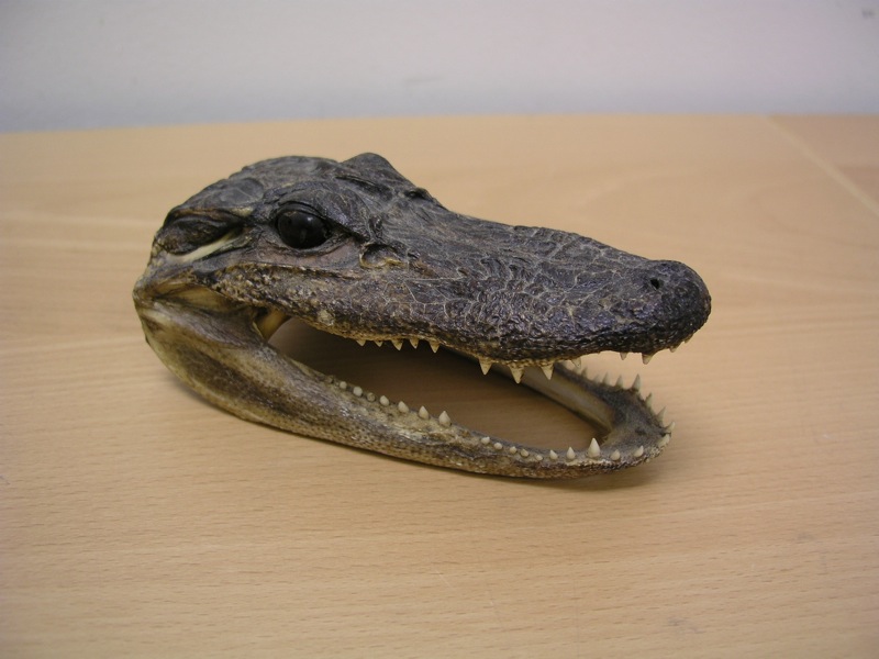
One must use their judgement when scanning the object to be sure to capture enough data to create the best mesh possible. The alligator head used here required around 30 scans taken from various angles. Typical scan sets may be as small as 5 and as large as 50. This was a high number due to all of the hidden geometry inside the mouth. For scans taken with a calibrated rotary turntable, the coarse alignment steps may be skipped entirely. However, it is still recommended to do a fine alignment to eliminate any error inherent to the turntable. As with any software, backup your work and save frequently.
One must use their judgement when scanning the object to be sure to capture enough data to create the best mesh possible. The alligator head used here required around 30 scans taken from various angles. Typical scan sets may be as small as 5 and as large as 50. This was a high number due to all of the hidden geometry inside the mouth. For scans taken with a calibrated rotary turntable, the coarse alignment steps may be skipped entirely. However, it is still recommended to do a fine alignment to eliminate any error inherent to the turntable. As with any software, backup your work and save frequently.
Cleaning Scan Data
Start by opening the first scan file. Chances are high that the object will be surrounded by a lot of extra data that does not need to be included in the final mesh. The easiest way to remove this data is to use Select Faces in a Rectangular Region tool. It allows you to use a marquee style selector to choose faces that you would like to remove. After selecting them, go to Filters/Selection/Delete Selected Faces and Vertices to remove them. This not only deletes the faces, but also removes the underlying point data, resulting a a cleaner mesh and smaller file size. Repeat this step for every scan and it is helpful to save the clean file as a new version, leaving the original intact. Save often!
Layering Mesh Files
Open up the new clean version of the first mesh file. Then go to File/Open as new layer and select the next two mesh files. This will import the new mesh files to separate layers, similar to an image editing program. Click on the layer icon to open the Layer Dialog window that allows you to view, hide or lock any of the layers.
Glueing the Meshes
You will now have three separate layers each with meshes that are not aligned. Close the Layer Dialog menu and click on the Align icon to open the Align tool. This tool is used to reposition the separate meshes in relation to each other. Click on the first mesh file in the menu and choose Glue Mesh Here. This will affix the mesh to a set location and allows the other meshes to be aligned to it.
Next, choose the second mesh and click on Point Based Glueing. This feature will use 4 or more user selected points to approximate the alignment of the second mesh in relationship to the first. When the alignment window opens it will display the first glued mesh and the second mesh, both with different colors to assist in the point selection. Rotate both models around and position them in a similar manner. Try to place them in a position that shows as much overlapping information as you can. Then, choose 4 or more similar points on each mesh. They don't have to be exact, but be as accurate as you can. After selecting the points, click OK.
If the selected points were close, the two meshes should automatically align. Again, they will not be exact, but should be extremely close. If you are happy with the alignment, click the Process button to align them even more accurately and to glue them in place.
More Glueing
Repeat the same process for the third mesh. If for any reason the mesh did not align as accurately as you would like, click the Unglue Mesh button and repeat the point based glueing process. This time choosing different points on the mesh.
Click the process button after the third mesh is aligned and save your new file. Processing the meshes after each new mesh is glued in place increases the accuracy of alignment. This technique provides the software with more data to help determine the appropriate location. As more and more meshes are aligned, the processing time increased, but the improved accuracy is worth the wait.
I suggest saving your work as project file at this stage because the project files automatically loads each layer into your file instead of having to manually open each file as a new layer all over again.
Tips on Alignment

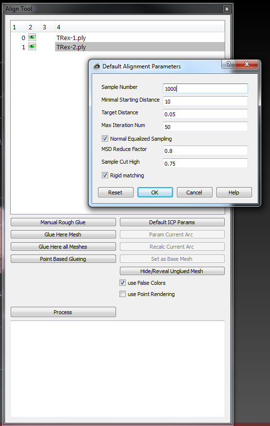
The default ICP parameter parameters allow you to fine tune how one mesh is aligned to another.
Sample Number - this is the number of samples it pulls from each mesh to compare to the other meshes. You do not want to make this number too big. A small sample typically works quiet well. 1,000 to 5,000 is usually plenty.
Minimal starting distance - this ignores any samples that are outside of this range. Typically for a manually aligned object you want this to be large enough to encompass your 'point picking' error. A value of 5 or 10 (in millimeters) is usually a good start. Once the initial alignements are complete, drop it down to 1mm to 'fine tune'
Target distance - this tells the algorithm when to stop. This is a function of your scanner and should be approx. equal (or slightly under) the specified error floor. Any smaller and you are just wasting time. You can also set it higher to align faster.
Max iteration number - related to target distance, it tells it when to stop regardless of target distance setting.
The remainder of the parameters are typically not needed.
In summary:
For a manually aligned scan, perform a rough align, then a fine align.
For a rotary aligned scan, perform a fine align.
For rough alignment - start with a small sample number, large starting distance and large target distance.
For fine alignement - start with a higher sample number, smaller starting distance and smaller target distance.
Also, running the alignment repeatedly will often serve to fine tune the alignment.
Flattening the Layers
After all the mesh files have been aligned and processed, click on the Layer icon to open the Layer Dialog menu. Double check to make sure that all of the aligned layers are visible. Then go to Filters/Layer and Attribute Management/Flatten visible layers. A pop-up window will open displaying the different options. I tend to leave the default options since I have saved often and it is easy to go back to a previous version. Click Apply. This will flatten all of the layers into one mesh that can then be run through a smoothing filter. At this point, if the scan data included color information, Meshlab will remove it from the new combined mesh.
Mesh Smoothing and Reconstruction
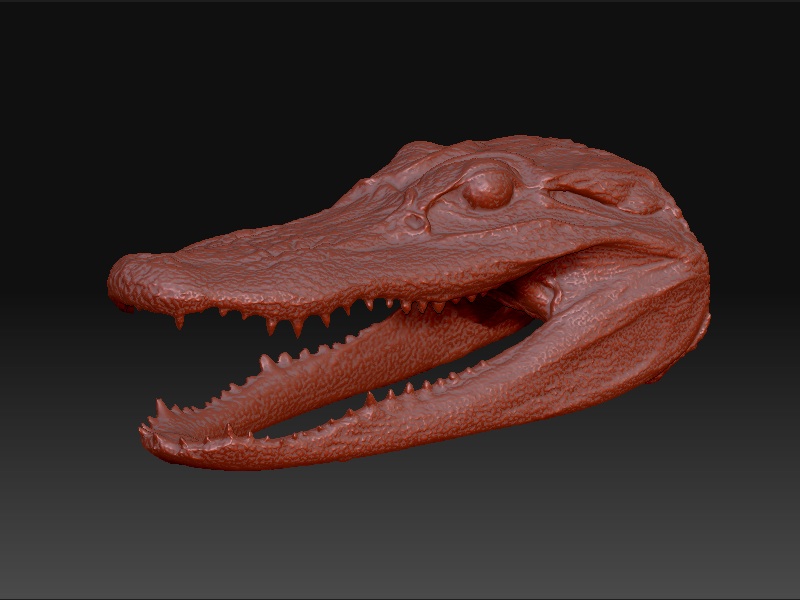
To create a smoothed mesh, click on Filters/Remeshing, simplification and reconstruction/Poisson Reconstruction. A pop-up window will open with several options. The settings that have brought the best results so far a and Octree Depth - 11, Solver Divide - 7, Sample per Node - 1 and Surface offsetting - 1, but you may find that different settings provide better results. Click Apply and let the process run its course.
It may take a while depending on the speed of your computer and the size of the mesh file. Once the process is finished, click on the Layer Dialog icon and hide the original mesh file. If you don't do this, it may appear that the process has failed. The new mesh will be watertight, meaning that there are no holes in the mesh and can be exported for rapid prototyping.
Meshlab is capable of exporting the watertight mesh into a variety of file formats such as .STL, .OBJ, .PLY, .3DS and .U3D among others. This makes it a great tool for converting your mesh into a format that can be imported into a 3D modeling program such as 3D Studio Max, Silo 3D, Blender or to integrate your file into .PDF file using Adobe Acrobat 9.
Exporting the Mesh

Meshlab is capable of exporting the watertight mesh into a variety of file formats such as .STL, .OBJ, .PLY, .3DS and .U3D among others. This makes it a great tool for converting your mesh into a format that can be imported into a 3D modeling program such as 3D Studio Max, Rhino, Silo 3D, Blender or to integrate your file into .PDF file using Adobe Acrobat Professional 9. Just go to File/Save As and choose the appropriate file format from the drop down menu. Importing the new files varies depending on the software you are using, but is generally a simple process.