Using LabVIEW LINX and ChipKIT WF32 to Control an LED Strip
by Sudharsan Sukumar in Circuits > Electronics
3304 Views, 8 Favorites, 0 Comments
Using LabVIEW LINX and ChipKIT WF32 to Control an LED Strip
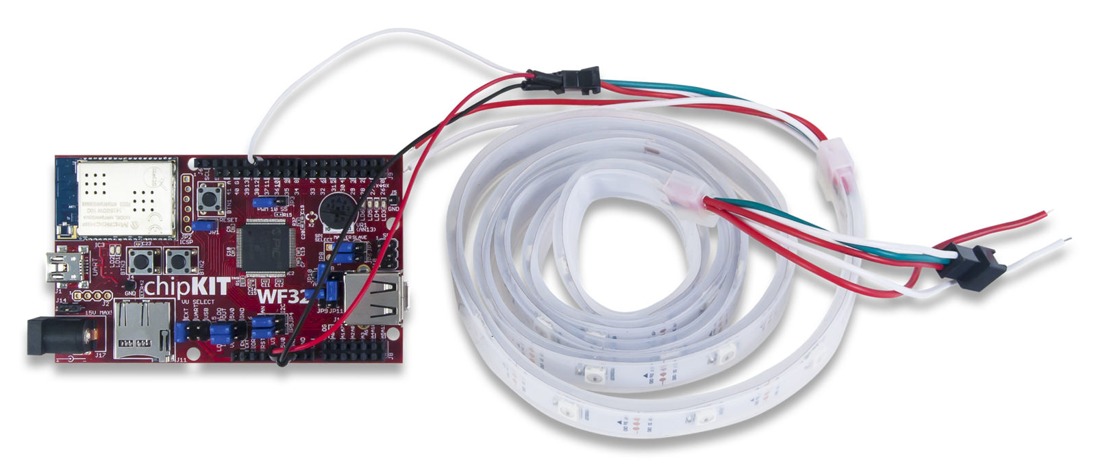
This Instructable will go over the steps involved in controlling the WS2812 LED strip using LabVIEW, LabVIEW MakerHub LINX, and chipKIT WF32.
Note - This project can be done using the LabVIEW Physical Computing Kit which contains both LabVIEW Home Bundle and chipKIT WF32 here.
Materials
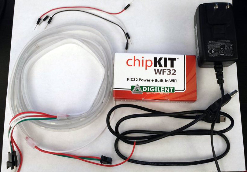
1) LabVIEW
LabVIEW Home Bundle can be used for this project and is sold by Digilent. Otherwise, any LabVIEW version can be used including the free trial.
2) chipKIT WF32
Installation is free and in depth instructions and video guides can be found here to learn how to install and use LINX. Just click "Getting Started."
5) 12VDC external power supply
6) WS2812 LED strip.
LabVIEW Setup
First, install LabVIEW onto your computer.
Next, install NI VISA here if you did not include it in your LabVIEW installation. Once that is completed, install LabVIEW MakerHub LINX here by clicking on download now from the attached page. A detailed installation instruction video can be found by clicking on "Getting Started."
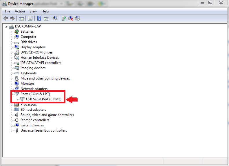
With all the required software installed, connect chipKIT WF32 to your PC using a USB A to mini B USB cable. Windows will most likely install the device drivers automatically. To make sure, open the device manager from the control panel and expand the Ports section. The COM port is the chipKIT WF32 and if the drivers were not installed correctly, a yellow exclamation mark will appear over the device.
If the drivers were not installed properly, download the drivers for your device which are included as part of MPIDE found at http://chipkit.net/started/install-chipkit-softwa... Once the drivers are installed, right click on the COM port for the chipKIT WF32 and click properties then click on port settings and choose advanced. Under the BM options, change the latency timer to 1 ms.
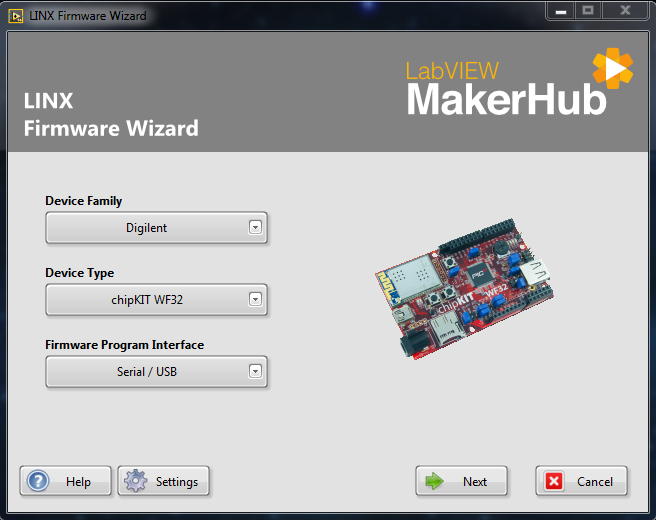
Now, launch LabVIEW and click tools --> MakerHub --> LINX --> LINX Firmware Wizard to deploy the LINX firmware to the chipKIT. Choose Digilent from device family and choose chipKIT WF32 from device type and click next (pictured above). Choose the COM port that the WF32 is connected to. Click next and then choose LINX serial/USB and click next again. The firmware will then be transferred to the WF32 and the on-board lights will flash.
Again, if you're having trouble with these steps, check out the guide on LabVIEW MakerHub for step-by-step video instructions.
LED Strip Setup
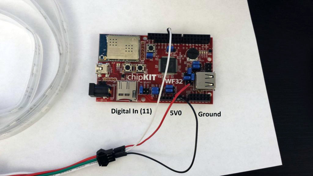
The next step is to connect the WF32 to the LED strip. On the WF32, the jumper on J15 should be moved to the EXT so that it will be powered by the 12VDC external power supply. This will allow the WF32 to supply 5V to the LED strip.
Connect the external power supply to J17 on the WF32 and then connect the red wire on the WS2812 to 5V0 located on the bottom part of the WF32 and connect the white wire on the WS2812 to ground located next to the 5V0 channel. Connect the green wire on the WS2812 to channel 11 located on the top part of the WF32. This is the digital channel that will control the LED strip.
Final Step
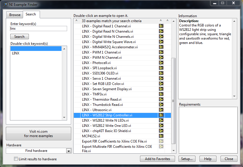
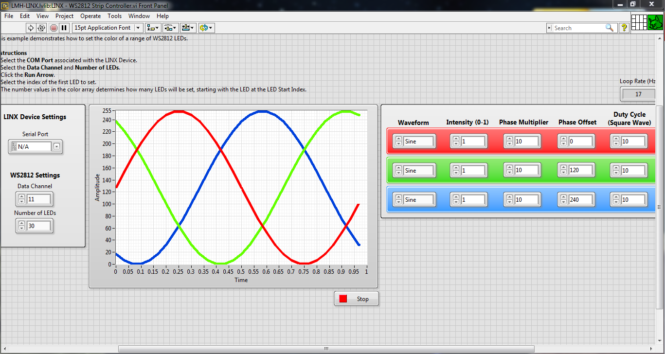
Open LabVIEW and, under the help tab, click on find examples. Once the NI Example Finder window opens, click on the search tab and search for "linx." Double click on "WS2812 Strip Controller.vi" to open the strip controller demo included in the LINX installer. Choose the COM port that corresponds to the WF32 and make sure digital channel 11 is chosen.
Click run and play with the controls located on the front panel to create different effects!
Hope you enjoy and let me know if you have any questions.