Using ESP8266-01 for Temp Monitoring
by funinalaska in Circuits > Microcontrollers
17540 Views, 49 Favorites, 0 Comments
Using ESP8266-01 for Temp Monitoring
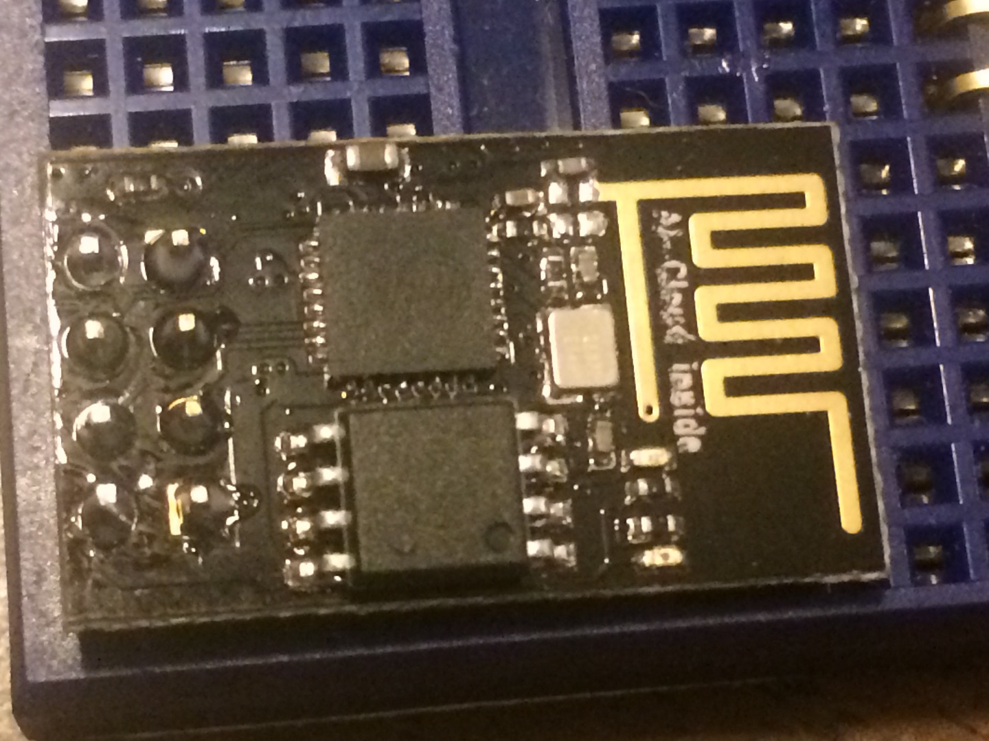
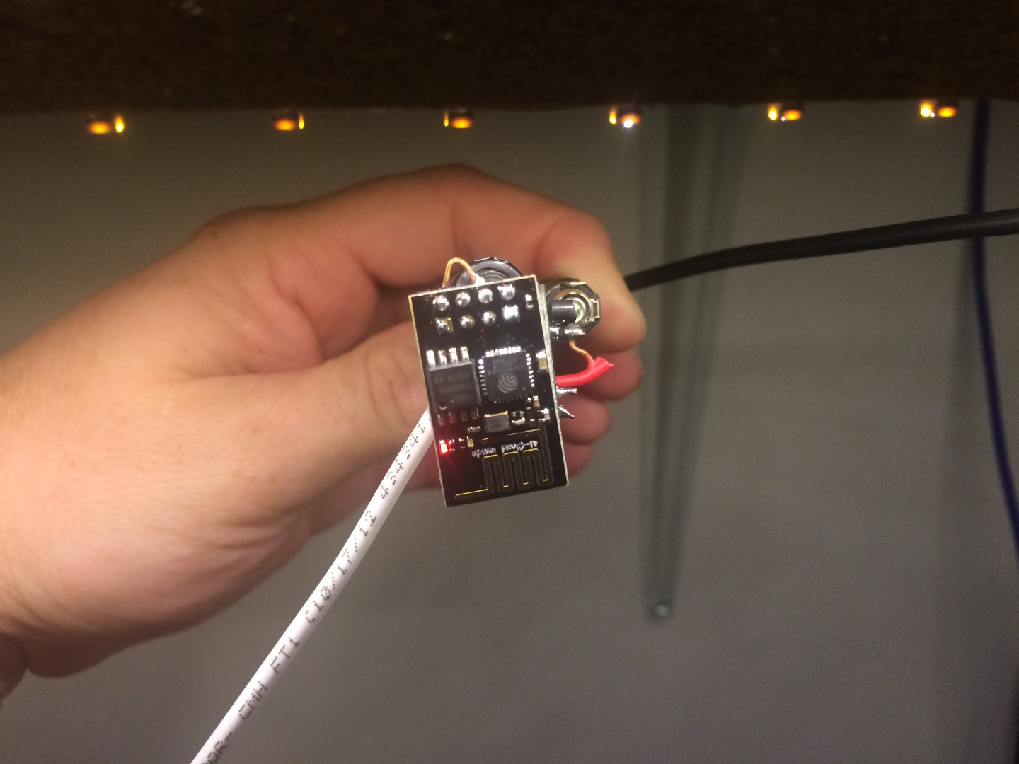
The ESP8266-01 is a very basic microcontroller unit with built in Wifi. It runs on 3.3v so be careful 5v will kill it.
The units are very cheap and easy to find on eBay.
This instructable is written assuming you have some understanding of what the following things are:
microcontrollers
Arduino
Arduino IDE
ISP (In system programmer)
and the basics of all those things.
My feed on thingspeak.com so you can see what the end goal is. I am not good with Java so this tutorial will only discuss how to get the graphs I am hoping to find some good information here soon to develop a slightly more convenient plugin but that will be down the road.
https://thingspeak.com/channels/51165
Shopping list:
ESP8266-01 module (can be found on ebay for less that $3 each if you don't mind waiting for shipping from China. I got mine from a domestic seller and cost me about $4.50 each)
DS18B20 Digital temperature sensors. (these can be found for less than $1 each especially if you buy them in lots of 10 or more.
You need a 3.3v power supply. I am using a 5-10v to 3.3v buck module for mine, they use the LMS1117 voltage regulator module. (These are very cheap I got 5 of them for $2.19) I am using that along with a standard 9v battery and battery terminal clip (CAUTION: DO NOT CONNECT IN REVERSE there is no reverse polarity protection on this regulator and one instant of reverse current will fry the module)
You need a serial to USB programmer I am using the FTDI232 that has the ability to work in 5v or 3.3v modes. (there are apparently ways to do this using an Arduino as ISP but I have not experimented with that as the Arduino is 5v signal which MAY damage the ESP modules)
You will need a resistor (I have used anything I have laying around from 10k ohm to 100k ohm)
We will be using the Arduino IDE and it must be version 1.6 (I am using 1.6.5) so you will need to download that here:
https://www.arduino.cc/en/Main/Software
We will be using the thingspeak.com website so you will need to go there and make a free account.
Finally some things that are useful. A breadboard, jumper wires both male to male and female to male either single row female header or a piece of 2X4 female header,
Setting Up Hardware to Program the ESP
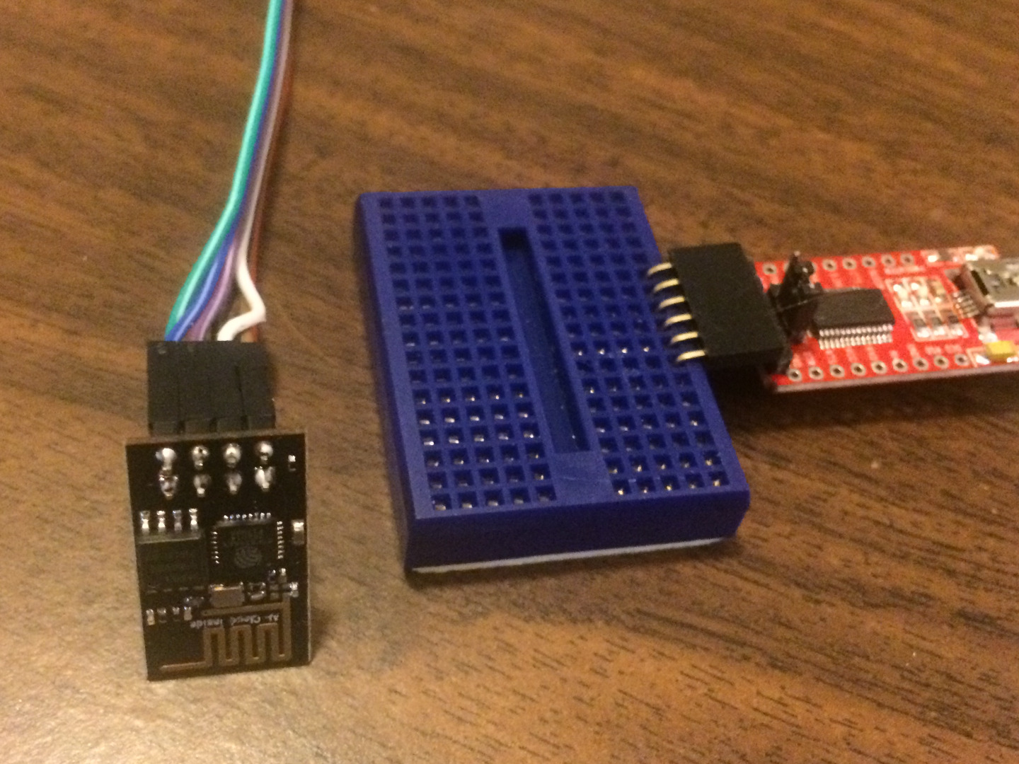
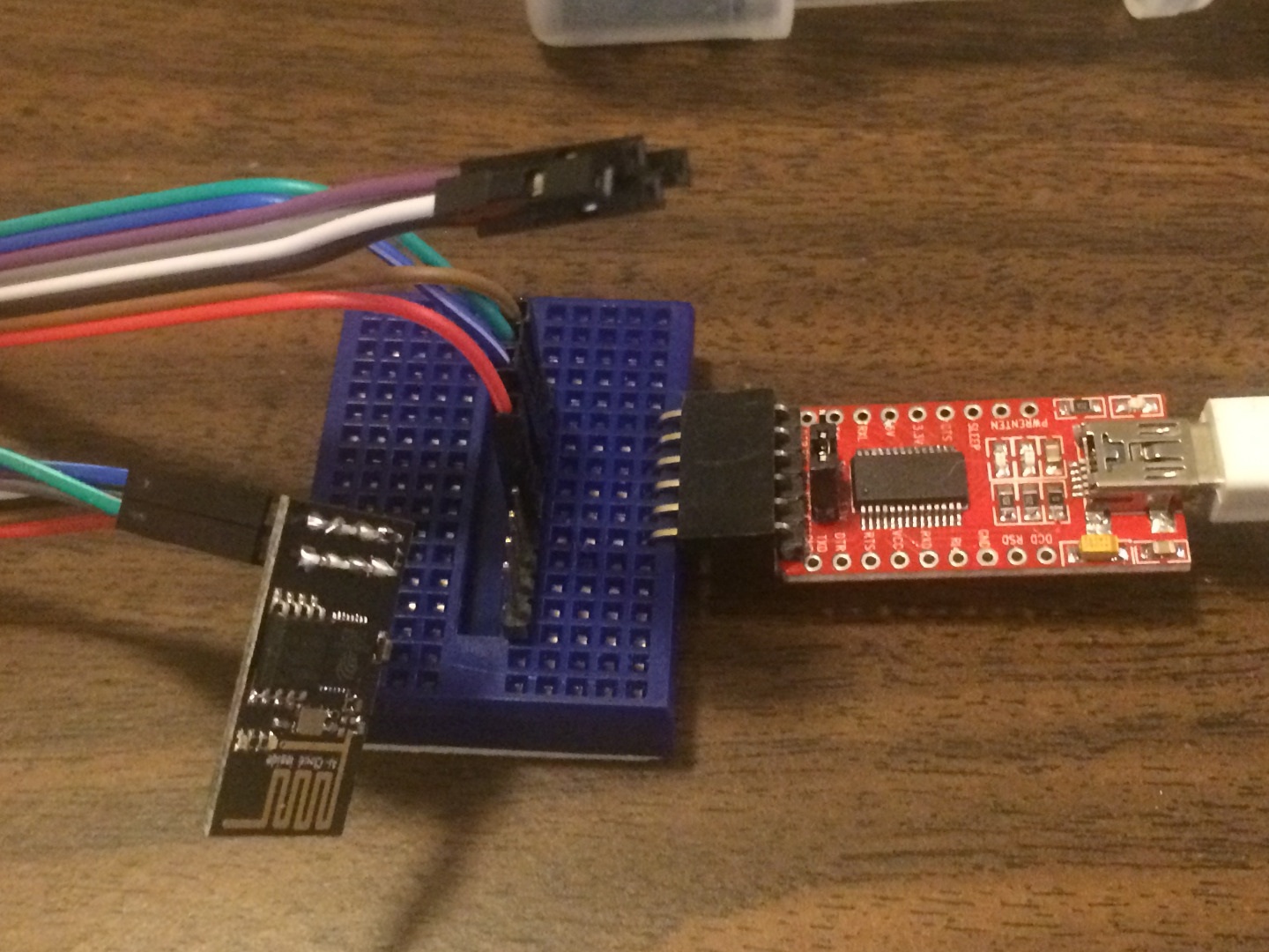
What I used:
a set of 8 female to male dupont cables
FTDI232 USB to serial programmer
A mini breadboard (but any size will work, it is just temporary)
We will be using the Arduino IDE to program the ESP module so you must have a version of Arduino IDE of 1.6 on your computer. We will be leaving the Expresif firmware on the ESP module as that is what the Arduino IDE will talk to. There are ways to do this if you have upgraded to LUA but I am not familiar with that.
So the hookup:
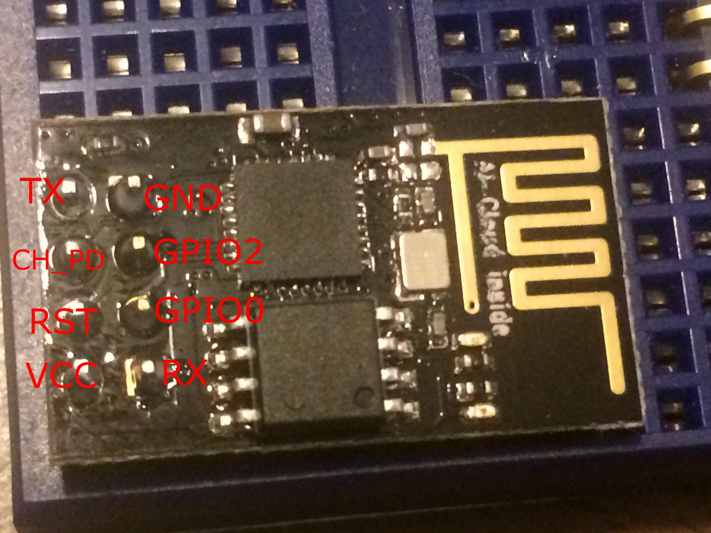
(See image for ESP8266 Pinout)
On the ESP module you want to connect:
The TX pin of the ESP to the RX of the FTDI
The RX pin of the ESP to the TX of the FTDI
The Gnd to Gnd
The VCC pin of the ESP to the VCC pin of the FTDI
For programming you also need to connect GPIO0 to GND
And always in this project we will connect CH_PD to VCC through a resistor (I've used anything from a 10k to a 100k without problem but I suggest between 10k and 47k)
Uploading the Sketch
In the Arduino IDE you need to set it up to to talk to the ESP8266 board
So open the IDE
Go to File > Preferences
In the "Additional Boards Manager URLs" box make sure that this address is present:
http://arduino.esp8266.com/stable/package_esp8266c...
Then exit and restart the Arduino IDE
Go to menu Tools > Board > Boards Manager
At the bottom of the list there will be
esp 8266 by ESP Community
Activate and install that item
Then quit and restart the Arduino IDE
Download the attached file "espDSdemo"
Place it inside a folder with the same name in the Arduino folder in your Documents folder
Open that file.
You need to edit a couple lines in the sketch:
String apiKey = "APIKEY";
const char* ssid = "SSID";
const char* password = "PASSWORD";
Change "APIKEY" to the API KEY that you get in your channel settings area of your ThingSpeak account.
Change "SSID" to the SSID of your local Wifi
Change "PASSWORD" to the password of your Wifi
In all 3 instances leave the quotation marks in place.
Next plug in your FTDI with it connected to the ESP to the USB port on your computer. Wait for it to be recognized by the computer and ready to go.
Next in the Arduino software
in the menu Tools > Board > Select the "Generic ESP8266 Module"
Everything else should set correctly once you select that other than the port. To select the port:
in the menu Tools > Port > Select the port number of your FTDI programmer
Now click the Right facing arrow at the top left of the Arduino window. This will tell the Arduino software to compile and upload the sketch to the ESP module.
When it says "Done uploading go ahead and disconnect the USB fro the computer.
Downloads
Testing the Sketch
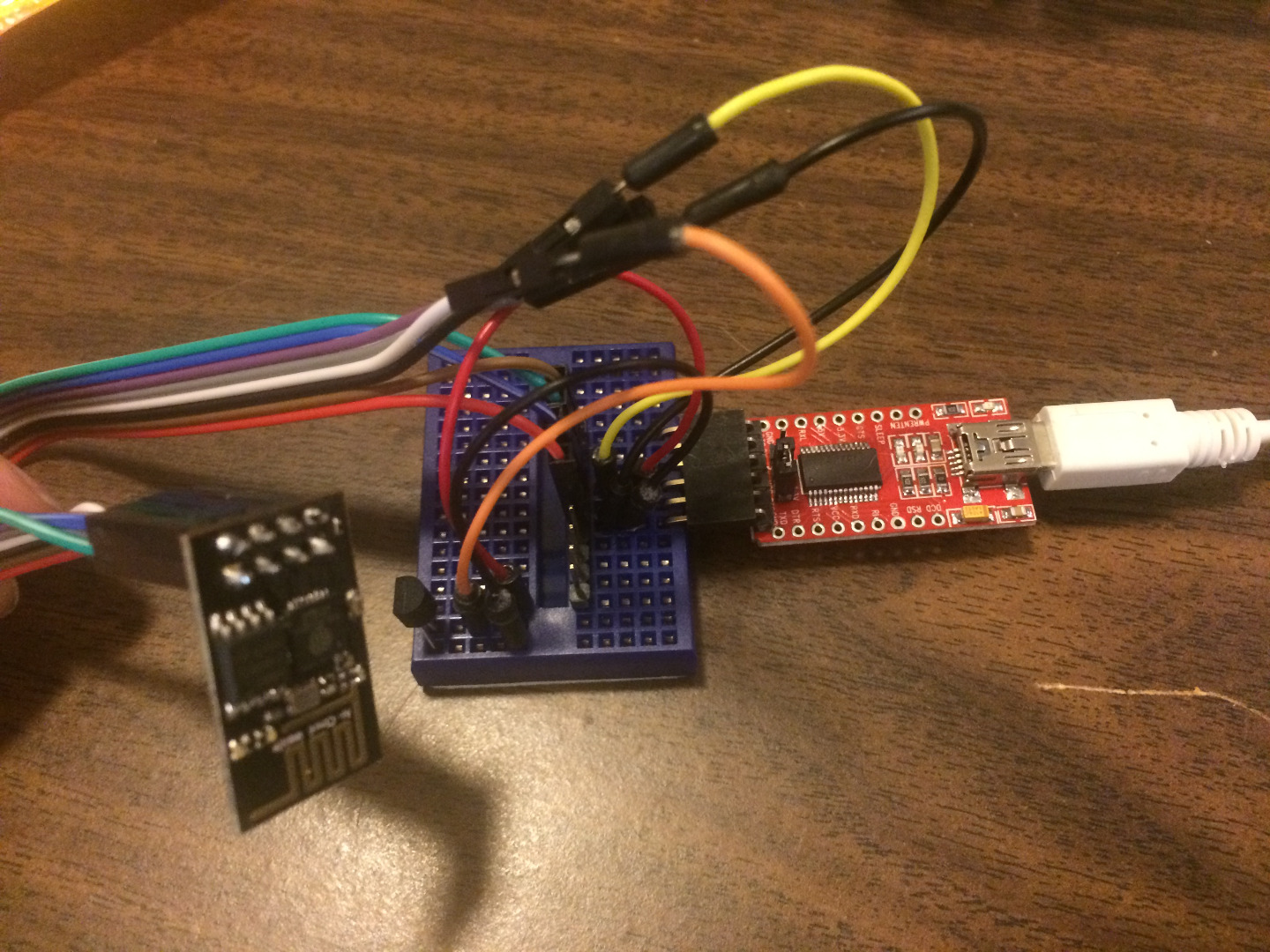
in this portion we will test the hardware and the sketch to see if everything is working.
First while the module is unplugged from the computer complete the rest of the circuit.
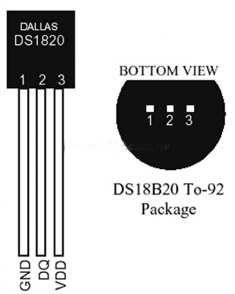
You want to put a DS18B20 sensor into your breadboard. using dupont lines you want to connect the DS18B20 in the following way:
Connect Pin 1 on the DS18B20 to GND on the ESP
Connect Pin 3 on the DS18B20 to VCC on the ESP
Connect pin 2 on the DS18B20 to GPIO2 on the ESP
You will also need to remove the jumper on GPIO0 from GND to take the module out of programming mode.
Now once all that is done you can reconnect the ESP module to your computer through the FTDI and USB.
As soon as your computer registers the FTDI as connected press the serial monitor button on the Arduino IDE (that is the button in the top right of the Arduino window that looks like a magnifying glass.
When the serial monitor comes up you may see information appear about the connectivity of the Wifi, but if it did not open soon enough you will see it give information about temperature readings and that those readings are being sent to ThingSpeak.
If all this is working properly now it is time to go to thingspeak and make sure your data is appearing.
If you have already set up your channel there should be a graph in the private view under your channel where points will begin to appear as the ESP sends the data.
If all this is working it is now time for you to make your project permanent if you wish.
The data it records on Thingspeak you can now see anywhere in the world that you can get into your account on Thingspeak. It is a great way to know your home is safe while you are away. Know if your heat went out, or if you will need the AC when you get home. Use this project to incorporate another element into your smart home. Or use it for what I am using it for to know if your house heats and cools evenly and efficiently (which mine does NOT).
Finishing and Using the Module
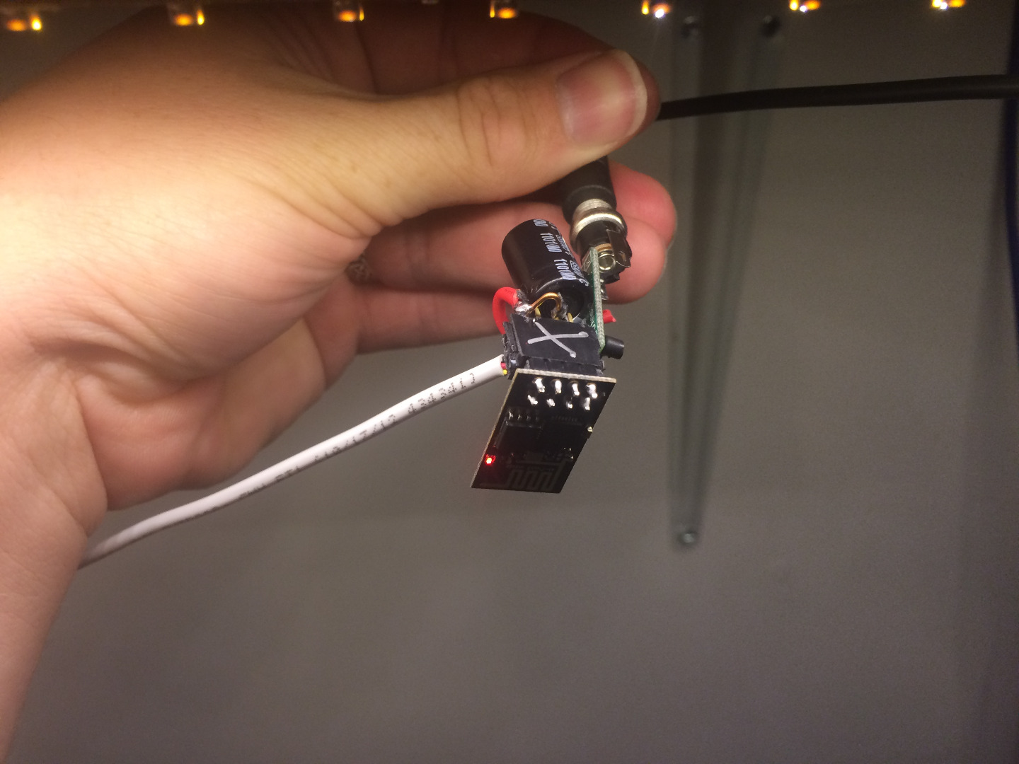
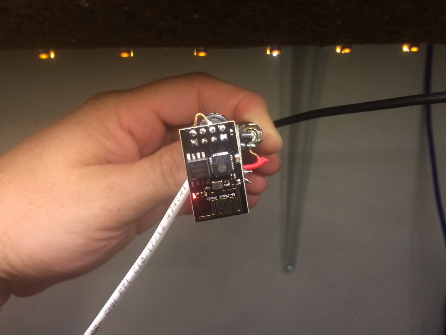
As of right now I decided to use some 5v power supplies I had laying around.
So I took a couple adjustable buck converters set them to around 3v and built what you see in the picture. (I have some LMS1117 modules on the way that I would prefer to be using but that boat from China seems to be exceptionally slow this time)
Because both the ESP module and the buck module create some heat I put the sensor on a wire a few inches away from the modules so there is less influence on the readings.
Basically all I did was take 2 pieces of female header 4 pins long each.
Super glued the together to make a 2X4 header (I am waiting for my 2X4s to come on a slow boat from China.)
The big capacitor you see is because the power from my power supply is kind of dirty so I just grabbed the first Cap I saw in my stash and soldered it across GND and VCC to smooth it out a bit. (If you do this make sure you have the polarity of the cap correct)
Everything else I just tried to keep as simple as I could. I kept the same connections as I had on the breadboard just eliminated the breadboard and as much wire as I could.
I do also have some enclosures both waterproof (for a planned outdoor unit) and standard I intend to put these in eventually.
You could easily assemble all this on a piece of perf board but I wanted to keep it small and three dimensional instead of making it larger and flat.
As far as finishing the ThingSpeak portion, there are any settings in the graphs you can play with. One of my sensors was giving me some bad points (It was occasionally throwing a -196.6 degree reading) I figured out this was most likely because of the dirty power. That is the reading the DS will throw if for some reason it does not have power. One way to fix that in the graph is to change the "min value" to a 0 or -20 or whatever you think will be the lowest temperature you will see. Unless you are using it for liquid nitrogen I don't think you will need that low. The DS18B20 is only good down to about -55 degrees anyway.
Reasons and Places to Use
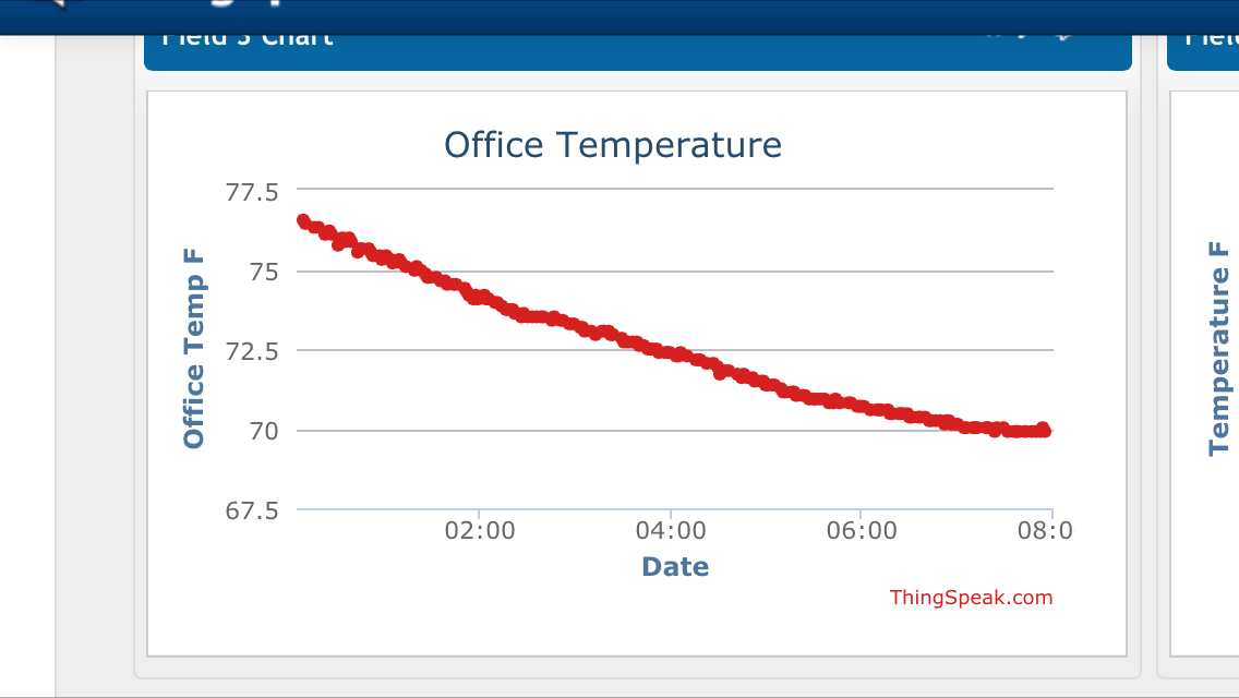
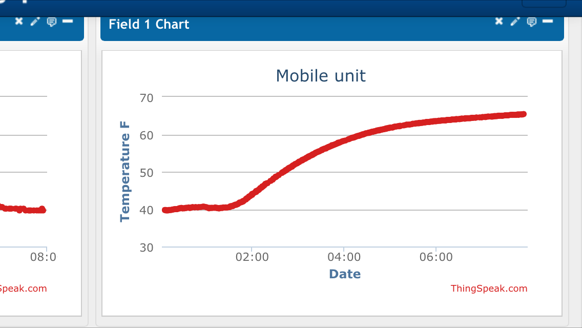
I got this idea because I was curious how different rooms in my house heated and cooled throughout a day.
So I am placing one of these modules in my:
Living Room
Attic
Office
Basement
Bedroom
Outside
And one I am keeping as a mobile unit I can place where I need. I am making that one have a waterproof sensor so I can use it to sense temperature of anything I'd like. Maybe my hot water tank, Or a glass of ice water on the counter just to have a graph of how long it takes to get to room temperature, Maybe of a duct on my furnace so I can see when my heat or AC is on.
I am in the process of making one of these modules in a sealed box using a waterproof version of the DS18B20 sensor to use as an outdoor thermometer. In the fullness of time I would like to make this module have a solar panel so that it can be placed outside and forgotten about. If anyone has any thoughts on doing that let me know. I am not all that familiar with Solar charging and powering.
Some Tips:
I have 3 of these modules set up currently and all reporting to the same channel on ThingSpeak. Because ThingSpeak will only allow one update every 15 seconds I have them all set with a slightly different delay at the end of the sketch. That way even if they do manage to sync up they don't remain in sync for very long. I like to get readings every couple minutes on all my sensors so I have one set to 117000 (117000 milliseconds or 117 seconds)
and I have one set to 123000 (123 seconds) and one set to 105000 (105 seconds) It seems that doing this makes them step on each other less. Once in a while I will be missing a value from one but not for an extended period of time. If you have them all set to the same time delay if they sync up they will likely stay in sync for a while. The other way around this is to have a separate channel for each module but I want to be able to compare the data so having it all in one place made more sense for me. Just remember that each channel has a separate API key and if you are sending multiples to the same channel you need to change the field it is sending to in the code.
This was my first instructable and I hope someone finds it useful.
I wrote this because I thought what I wanted to do was something simple that should be easy to do, but I had to search through many different tutorials and combine a few different methods to finally get what I really wanted. I hope this makes sense to you and that you get some use out of it.
Feel free to comment if you build this and let me know how it works out for you. If you wish to, you may also link to your ThingSpeak channel in the comments so others can see different ways of using this instructable.