Using Autodesk Inventor to Create a Notched Wood Construction (Jeweler's Bench Tool Holder)
by TomCloss in Workshop > Tools
13486 Views, 60 Favorites, 0 Comments
Using Autodesk Inventor to Create a Notched Wood Construction (Jeweler's Bench Tool Holder)
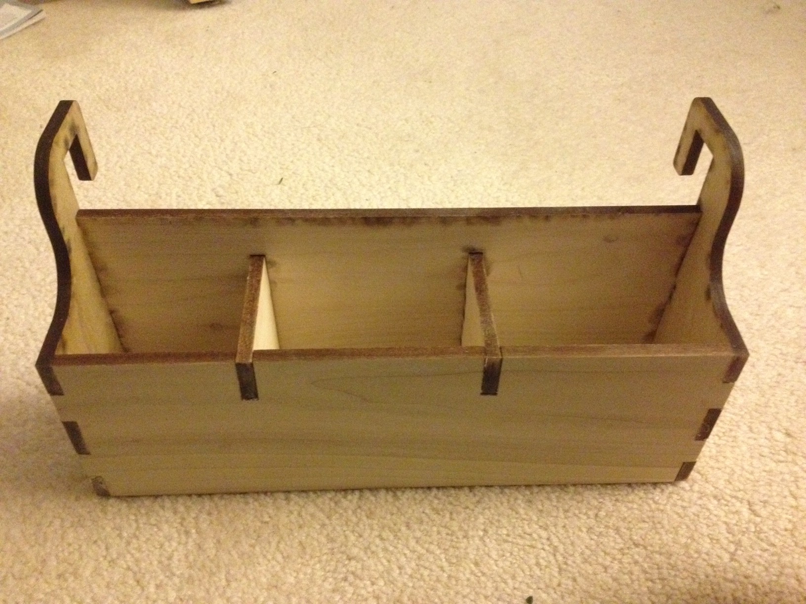
As I spend a lot of my creating time on making jewelry, my jeweler's bench gets covered in tools so I needed more storage space for my tools. So I designed this tool holder in Inventor and as doing it I thought it would be good to share some of the techniques I used in the design process. So here it is.
I made this at TechShop. For more information in Techshop Click Here
I made this at TechShop. For more information in Techshop Click Here
Downloads
Initial Design
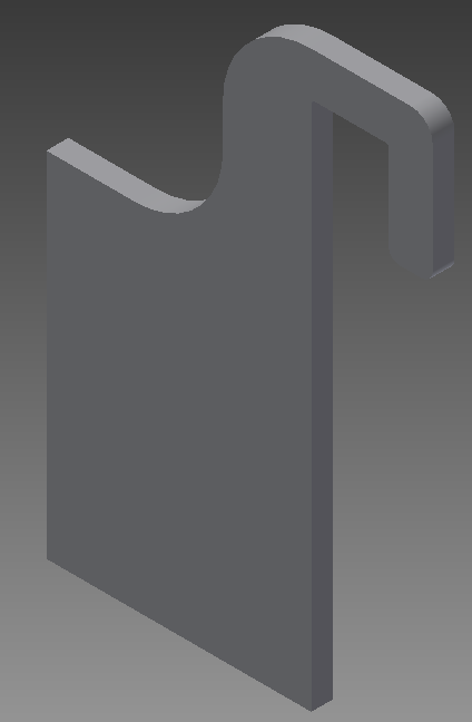
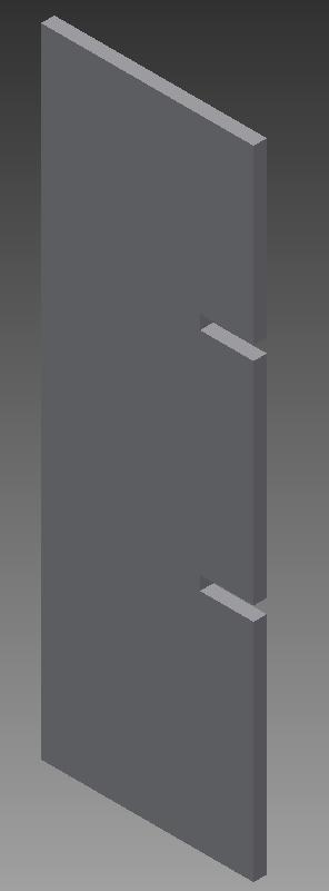
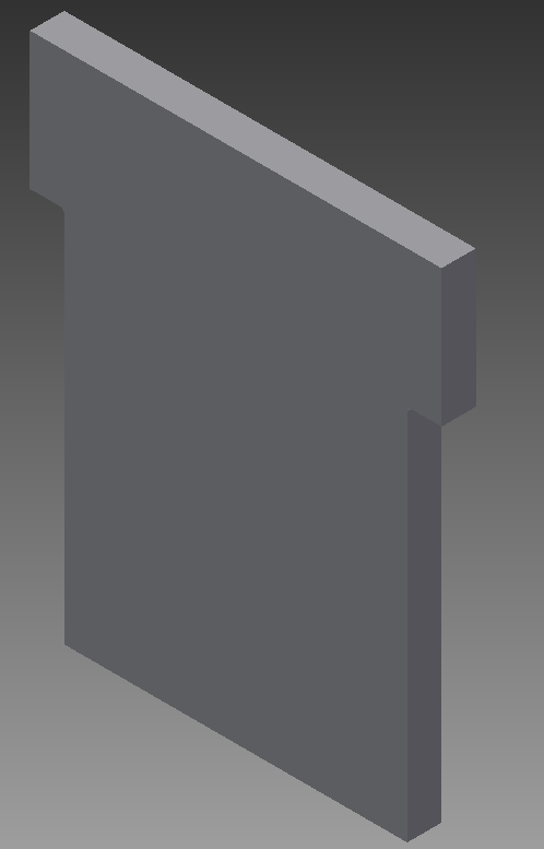
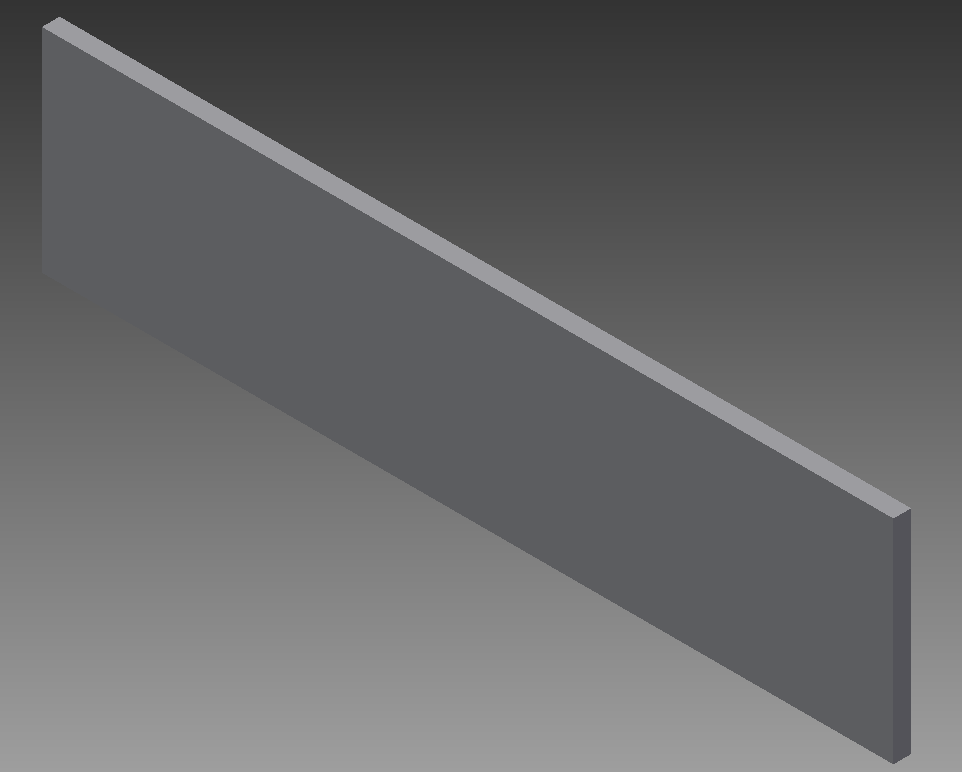
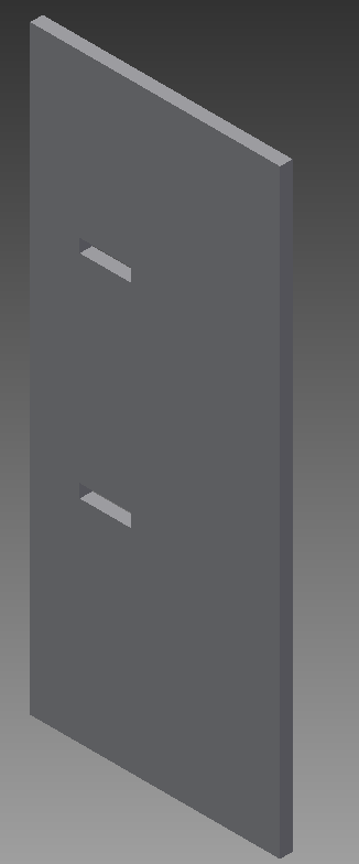
The first step was to design the tool holder in Inventor. Each piece will be cut from 1/4 inch piece of wood with a laser cutter. For this we need to design each piece as a separate Inventor part.
Assemble the Pieces
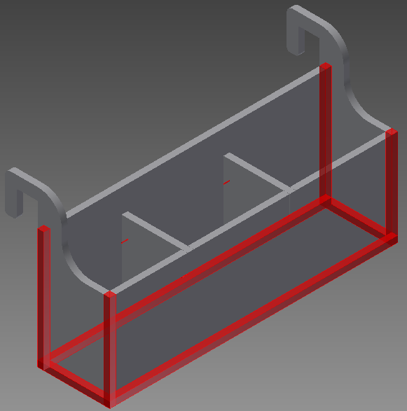
After the pieces are modeled they need to be assembled to help define where to cut the notches. The image provided shows how each piece is overlapped during the assembly.
Add a Parameter for Kerf


As I mentioned we will be cutting the pieces out using a laser cutter so we need to keep the Kerf in mind when adding the notches. For more information on Kerf see this Instructable. For each piece we will add a parameter to adjust the tab size on the fly. To add the parameter select the "Manage" Tab. Once the Parameter dialog box is up add a parameter named Kerf and set the value to the Kerf of the laser cutter being used to cut the pieces.
Add Notches
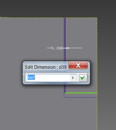
When adding the notches draw the notches with construction lines first. After adding the construction geometry outline the construction geometry with regular geometry and add a dimension between the construction geometry and regular geometry make the dimension value the parameter Kerf. This will allow the adjustment of the Kerf by simply changing the parameter.
Layout the Pieces for Cutting
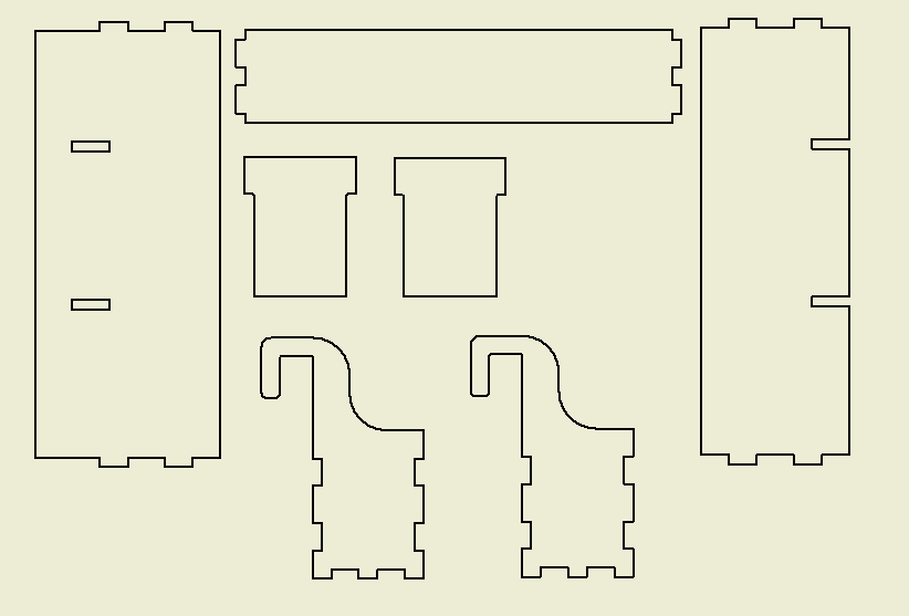
Using an Inventor drawing place a flat view of each piece needed to be cut on the drawing sheet.
Saving the Layout
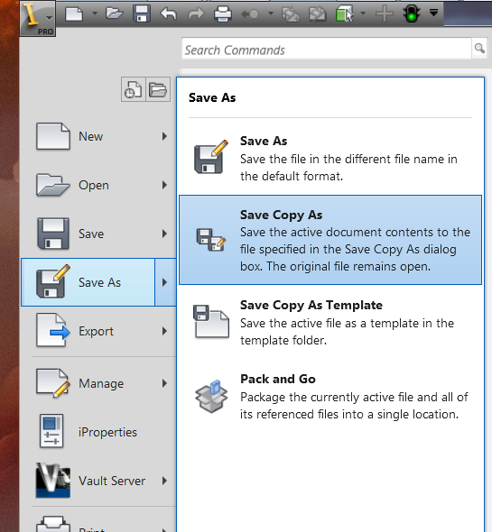
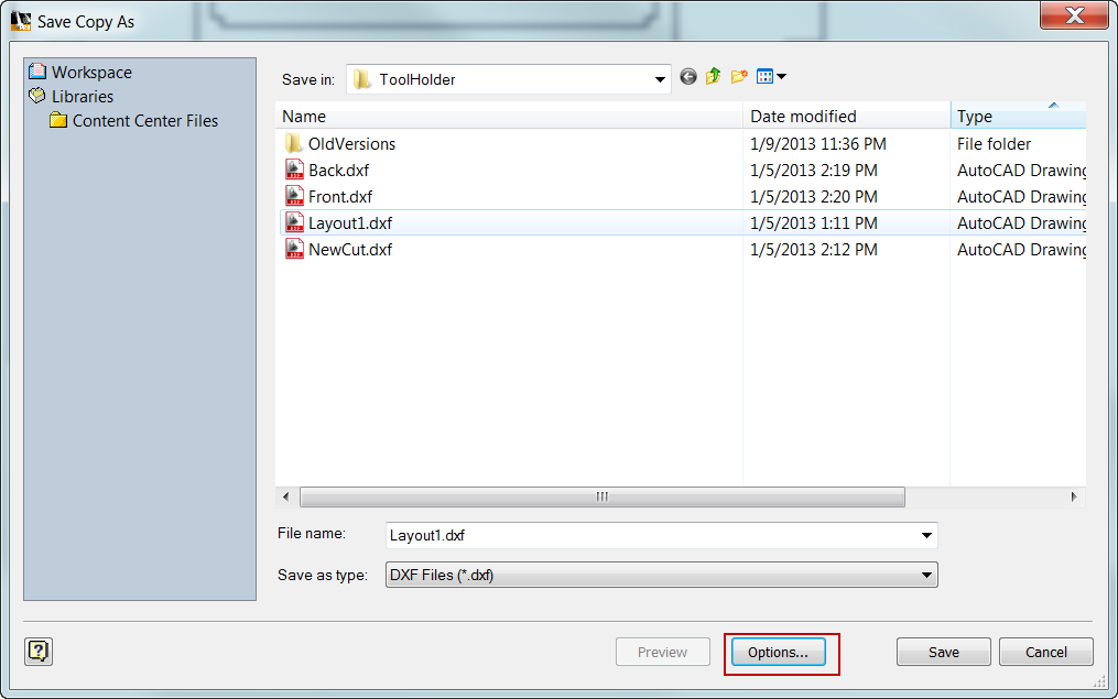
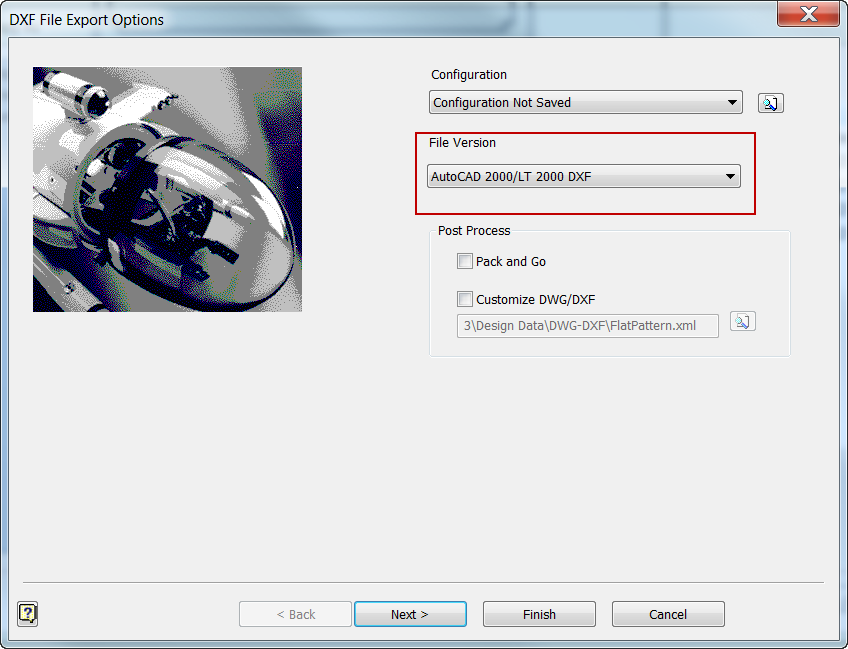
Once the layout is created the file needs to be saved in a format that can be opened in Corel Draw. To do this from the Inventor idw, you need to do a "Save Copy As". Once the the "Save Copy As" dialog box appears you need to change the Save as type to "*.dxf". To make the import into Corel Draw easier click the options button and change the File Version to "AutoCAD 2000/LT 2000 DXF"
Determine the Kerf for the Laser Cutter
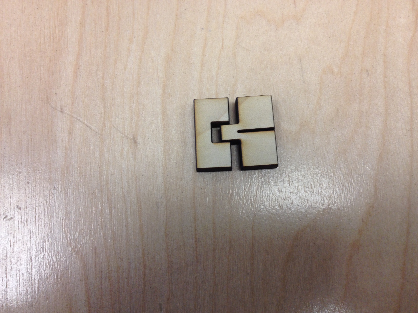
Determine the Kerf for your laser cutter using this Instructable as a reference. Once you know your Kerf adjust the Kerf parameter in each Inventor part. Open the layout idw file and it will automatically update so all you need to do is save out the file as a dxf.
Cut the Pieces
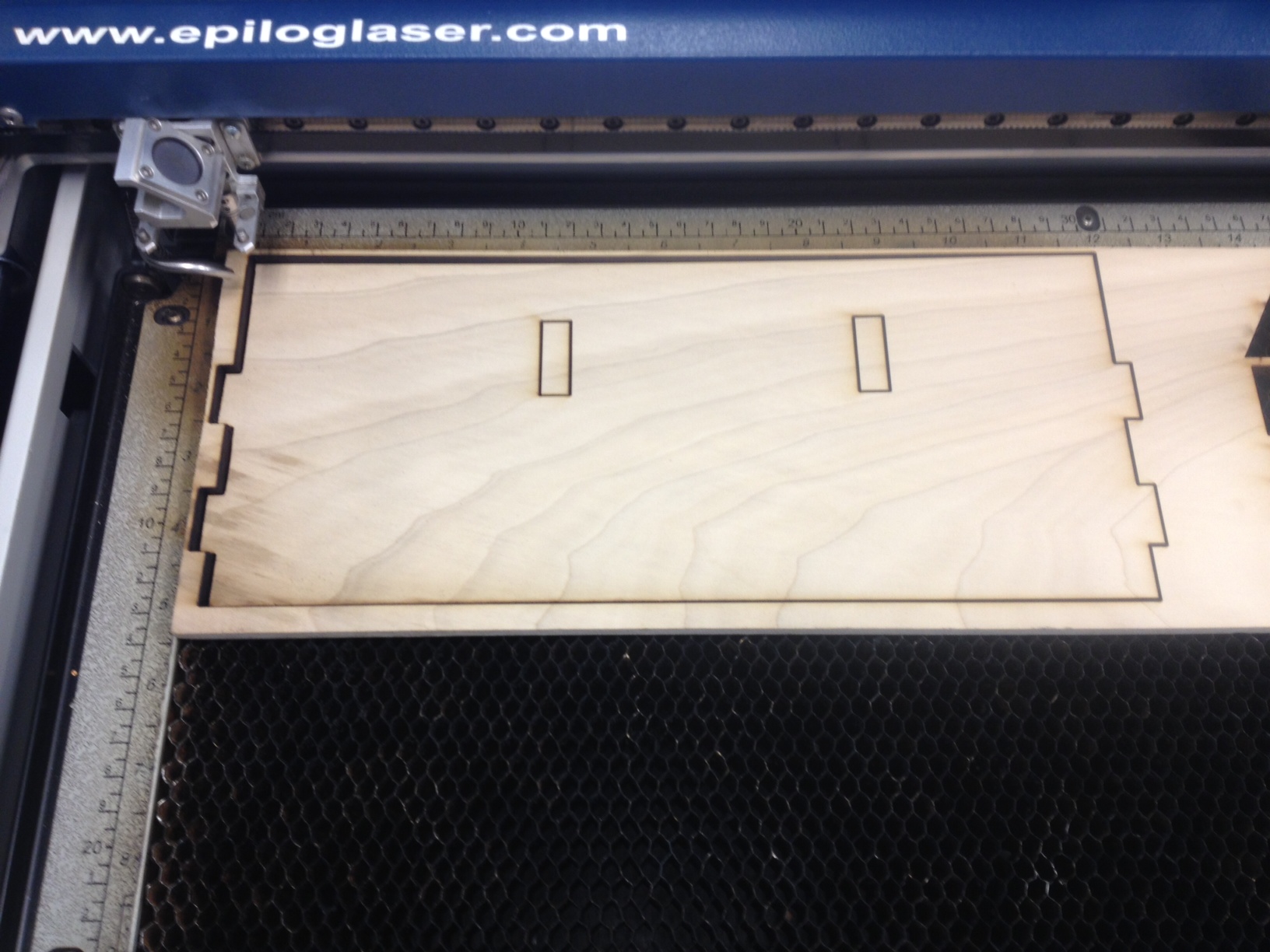
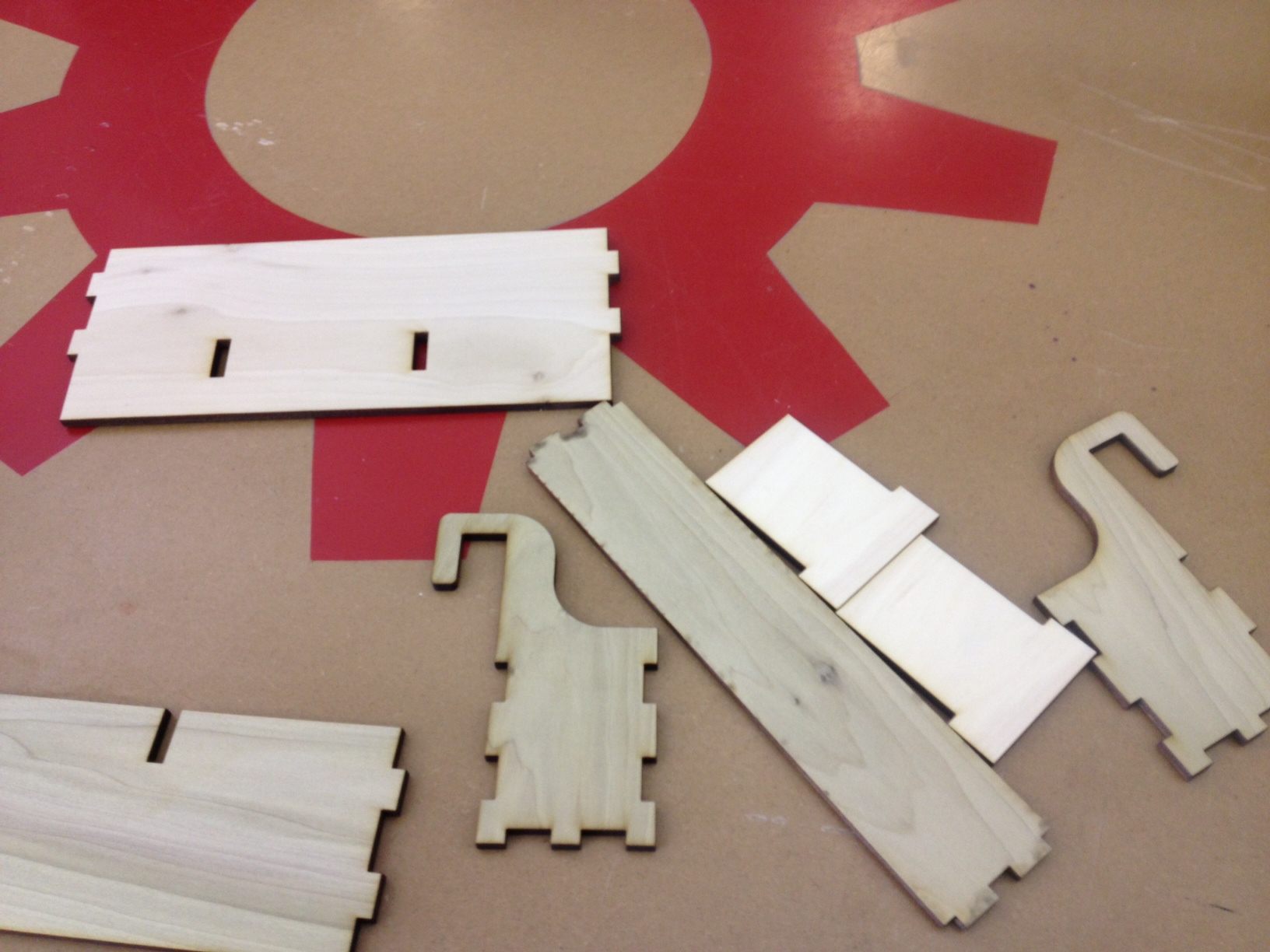
Import the dxf file into Corel Draw and cut the pieces out.
Assemble the Holder

Assemble the tool holder by tapping the pieces together with a rubber mallet if need be. If the pieces don't fit together tightly you can add a little glue to each piece as you assemble them.
Use the Tool Holder
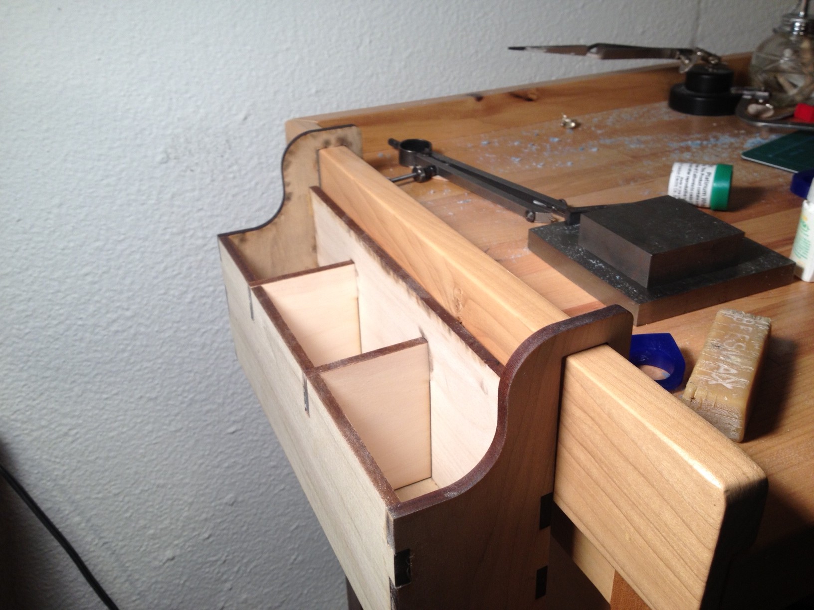
Simply apply the tool holder to the bench and add tools. As you can see I need the room.