Using Arduino Uno for XYZ Positioning of 6 DOF Robotic Arm
41795 Views, 28 Favorites, 0 Comments
Using Arduino Uno for XYZ Positioning of 6 DOF Robotic Arm
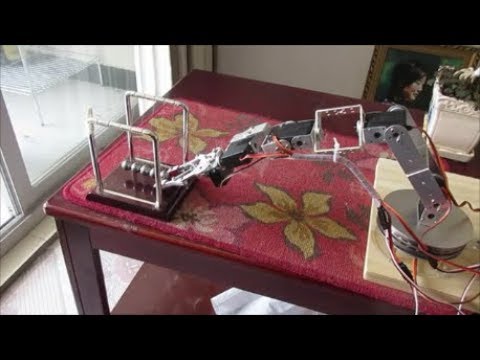
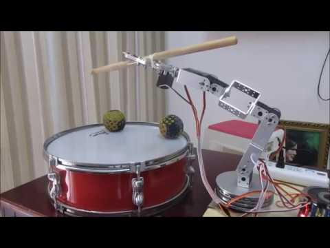
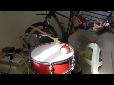
This project is about implementing a short and relatively easy Arduino sketch to provide XYZ inverse kinematic positioning. I had built a 6 servo robotic arm but when it came to finding software to run it, there wasn't much out there except for custom programs running on custom servo shields like the SSC-32(U) or other programs and apps that were complicated to install and communicate with the arm. Then I found Oleg Mazurov's most excellent "Robotic Arm Inverse Kinematics on Arduino" where he implemented inverse kinematics in a simple Arduino sketch.
I made two modifications to adapt his code:
1. I used the VarSpeedServo library in place of his custom servo shield library because I could then control the speed of the servos and I wouldn't have to use the servo shield he used. For any one considering running the code provided here I recommend that you use this VarSpeedServo library,rather than the servo.h library, so that you can slow down your robotic arm movement during development or you may find that the arm will unexpectedly poke you in the face or worse because it will be moving at full servo speed.
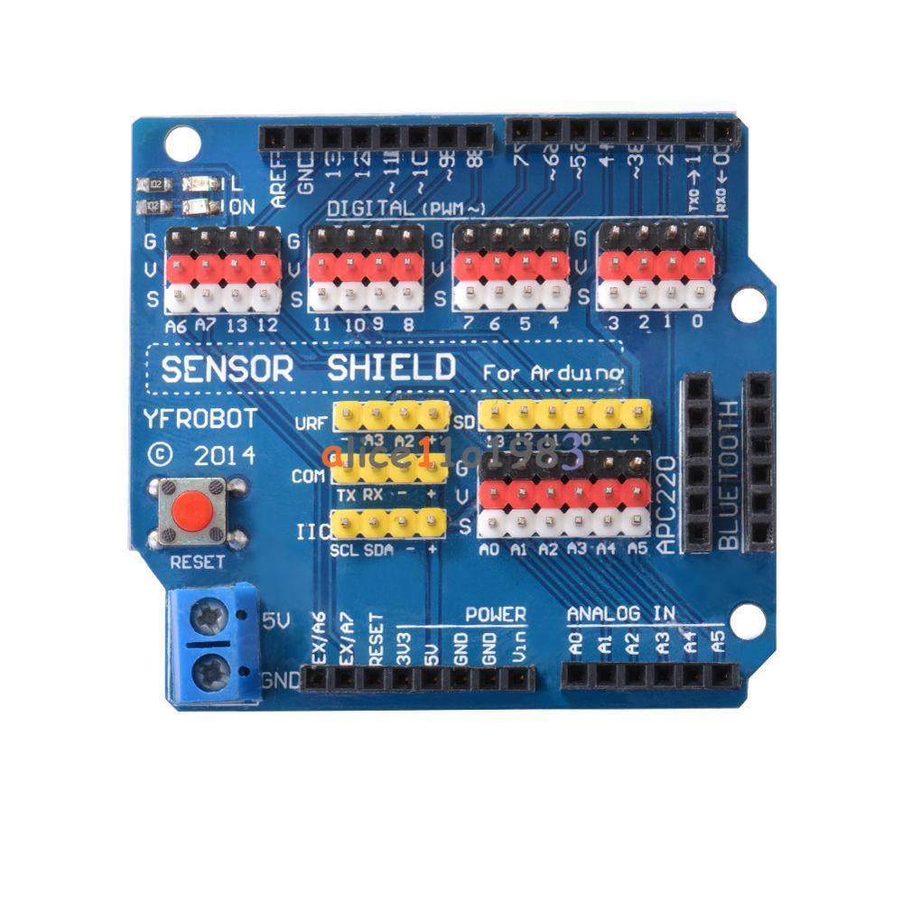
2. I use a simple sensor/servo shield to connect the servos to the Arduino Uno but it requires no special servo library as it just uses the Arduino's pins. It only costs a few bucks but it is not required. It makes for a nice clean connection of the servos to the Arduino. And I will never go back to hardwiring servos to the Arduino Uno now. If you use this sensor/servo shield you need to make one minor modification that I will outline below.
The code works great and allows you to operate the arm by using a single function in which you pass the x,y,x and speed parameters. For example:
set_arm( 0, 240, 100, 0 ,20); // parameters are (x,y,z,gripper angle,servo speed)
delay(3000); // delay is required to allow arm time to move to this location
Couldn't be simpler. I will include the sketch below.
Oleg's video is here: Controlling Robotic Arm with Arduino and USB Mouse
Oleg's original program, descriptions, and resources:Oleg's Inverse Kinematics for Arduino Uno
I don't understand all the math behind the routine but the nice thing is you don't have to to use the code. Hope you will give it a try.
Hardware Modifcations
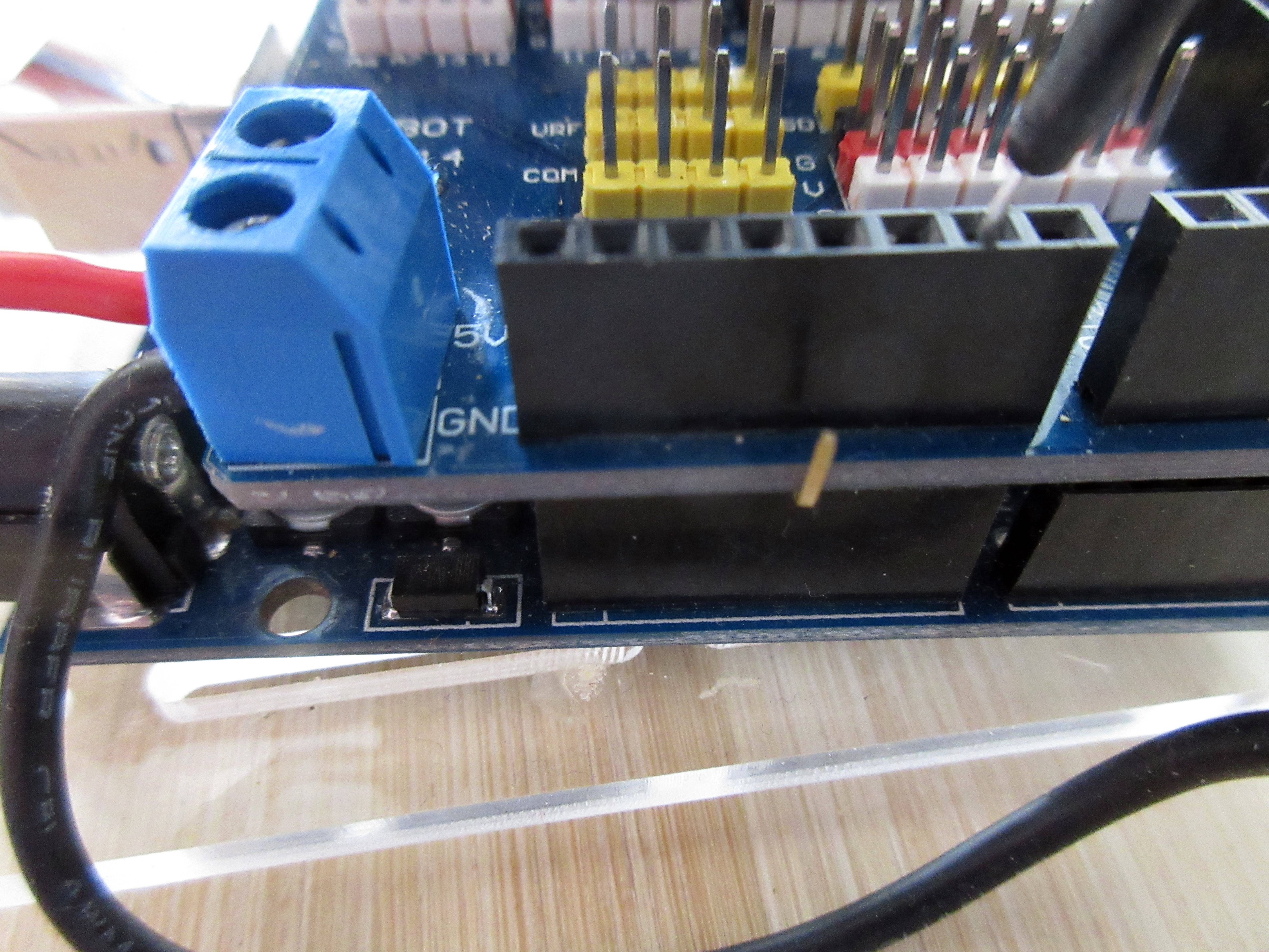
1. The only thing that is required is that your servo turns in the expected directions which could require you to physically reverse the mounting of your servos. Go to this page to see the expected servo direction for base, shoulder, elbow, and wrist servos: http://www.micromegacorp.com/downloads/documentati...
2. If you use the sensor shield that I am using you need to do one thing to it: bend the pin that connects the 5v from the shield to the Arduino Uno out of the way so that it does not connect to the Uno board. You want to use the external voltage on the shield to power only your servos, not the Arduino Uno or it may destroy the Uno, I know as I burned up two Uno boards when my external voltage was 6 volts rather than 5. This allows you to use higher than 5v to power your servos but if your external voltage is higher than 5 volts then do not connect any 5 volt sensors to the shield or they will be fried.
Download the VarSpeedServo Library
You need to use this library that replaces the standard arduino servo library because it allows you to pass a servo speed into the servo write statement. The library is located here:
You can just use the zip button, download the zip file and then install it with the Arduino IDE. Once installed the command in your program will look like: servo.write(100,20);
The first parameter is the angle and the second is the speed of the servo from 0 to 255(full speed).
Run This Sketch
Here is the compete program. You need to modify a few parameters for your robotic arm dimentions:
1. BASE_HGT,HUMERUS,ULNA,GRIPPER lengths in millimeters.
2. Input your servo pin numbers
3. Input the servo min and max in the attach statements.
4. Then try a simple set_arm() command and then the zero_x(), line() and circle() functions for testing. Be sure your servo speed is low the first time you run these functions to prevent damaging your arm and your own arm.
Good luck.
#include VarSpeedServo.h
/* Servo control for AL5D arm */
/* Arm dimensions( mm ) */
#define BASE_HGT 90 //base height
#define HUMERUS 100 //shoulder-to-elbow "bone"
#define ULNA 135 //elbow-to-wrist "bone"
#define GRIPPER 200 //gripper (incl.heavy duty wrist rotate mechanism) length "
#define ftl(x) ((x)>=0?(long)((x)+0.5):(long)((x)-0.5)) //float to long conversion
/* Servo names/numbers *
* Base servo HS-485HB */
#define BAS_SERVO 4
/* Shoulder Servo HS-5745-MG */
#define SHL_SERVO 5
/* Elbow Servo HS-5745-MG */
#define ELB_SERVO 6
/* Wrist servo HS-645MG */
#define WRI_SERVO 7
/* Wrist rotate servo HS-485HB */
#define WRO_SERVO 8
/* Gripper servo HS-422 */
#define GRI_SERVO 9
/* pre-calculations */
float hum_sq = HUMERUS*HUMERUS;
float uln_sq = ULNA*ULNA;
int servoSPeed = 10;
//ServoShield servos; //ServoShield object
VarSpeedServo servo1,servo2,servo3,servo4,servo5,servo6;
int loopCounter=0;
int pulseWidth = 6.6;
int microsecondsToDegrees;
void setup()
{
servo1.attach( BAS_SERVO, 544, 2400 );
servo2.attach( SHL_SERVO, 544, 2400 );
servo3.attach( ELB_SERVO, 544, 2400 );
servo4.attach( WRI_SERVO, 544, 2400 );
servo5.attach( WRO_SERVO, 544, 2400 );
servo6.attach( GRI_SERVO, 544, 2400 );
delay( 5500 );
//servos.start(); //Start the servo shield
servo_park();
delay(4000);
Serial.begin( 9600 );
Serial.println("Start");
}
void loop()
{
loopCounter +=1;
//set_arm( -300, 0, 100, 0 ,10); //
//delay(7000);
//zero_x();
//line();
//circle();
delay(4000);
if (loopCounter > 1) {
servo_park();
//set_arm( 0, 0, 0, 0 ,10); // park
delay(5000);
exit(0); }//pause program - hit reset to continue
//exit(0);
}
/* arm positioning routine utilizing inverse kinematics */
/* z is height, y is distance from base center out, x is side to side. y,z can only be positive */
//void set_arm( uint16_t x, uint16_t y, uint16_t z, uint16_t grip_angle )
void set_arm( float x, float y, float z, float grip_angle_d, int servoSpeed )
{
float grip_angle_r = radians( grip_angle_d ); //grip angle in radians for use in calculations
/* Base angle and radial distance from x,y coordinates */
float bas_angle_r = atan2( x, y );
float rdist = sqrt(( x * x ) + ( y * y ));
/* rdist is y coordinate for the arm */
y = rdist;
/* Grip offsets calculated based on grip angle */
float grip_off_z = ( sin( grip_angle_r )) * GRIPPER;
float grip_off_y = ( cos( grip_angle_r )) * GRIPPER;
/* Wrist position */
float wrist_z = ( z - grip_off_z ) - BASE_HGT;
float wrist_y = y - grip_off_y;
/* Shoulder to wrist distance ( AKA sw ) */
float s_w = ( wrist_z * wrist_z ) + ( wrist_y * wrist_y );
float s_w_sqrt = sqrt( s_w );
/* s_w angle to ground */
float a1 = atan2( wrist_z, wrist_y );
/* s_w angle to humerus */
float a2 = acos((( hum_sq - uln_sq ) + s_w ) / ( 2 * HUMERUS * s_w_sqrt ));
/* shoulder angle */
float shl_angle_r = a1 + a2;
float shl_angle_d = degrees( shl_angle_r );
/* elbow angle */
float elb_angle_r = acos(( hum_sq + uln_sq - s_w ) / ( 2 * HUMERUS * ULNA ));
float elb_angle_d = degrees( elb_angle_r );
float elb_angle_dn = -( 180.0 - elb_angle_d );
/* wrist angle */
float wri_angle_d = ( grip_angle_d - elb_angle_dn ) - shl_angle_d;
/* Servo pulses */
float bas_servopulse = 1500.0 - (( degrees( bas_angle_r )) * pulseWidth );
float shl_servopulse = 1500.0 + (( shl_angle_d - 90.0 ) * pulseWidth );
float elb_servopulse = 1500.0 - (( elb_angle_d - 90.0 ) * pulseWidth );
//float wri_servopulse = 1500 + ( wri_angle_d * pulseWidth );
//float wri_servopulse = 1500 + ( wri_angle_d * pulseWidth );
float wri_servopulse = 1500 - ( wri_angle_d * pulseWidth );// updated 2018/2/11 by jimrd - I changed the plus to a minus - not sure how this code worked for anyone before. Could be that the elbow servo was mounted with 0 degrees facing down rather than up.
/* Set servos */
//servos.setposition( BAS_SERVO, ftl( bas_servopulse ));
microsecondsToDegrees = map(ftl(bas_servopulse),544,2400,0,180);
servo1.write(microsecondsToDegrees,servoSpeed); // use this function so that you can set servo speed //
//servos.setposition( SHL_SERVO, ftl( shl_servopulse ));
microsecondsToDegrees = map(ftl(shl_servopulse),544,2400,0,180);
servo2.write(microsecondsToDegrees,servoSpeed);
//servos.setposition( ELB_SERVO, ftl( elb_servopulse ));
microsecondsToDegrees = map(ftl(elb_servopulse),544,2400,0,180);
servo3.write(microsecondsToDegrees,servoSpeed);
//servos.setposition( WRI_SERVO, ftl( wri_servopulse ));
microsecondsToDegrees = map(ftl(wri_servopulse),544,2400,0,180);
servo4.write(microsecondsToDegrees,servoSpeed);
}
/* move servos to parking position */
void servo_park()
{
//servos.setposition( BAS_SERVO, 1500 );
servo1.write(90,10);
//servos.setposition( SHL_SERVO, 2100 );
servo2.write(90,10);
//servos.setposition( ELB_SERVO, 2100 );
servo3.write(90,10);
//servos.setposition( WRI_SERVO, 1800 );
servo4.write(90,10);
//servos.setposition( WRO_SERVO, 600 );
servo5.write(90,10);
//servos.setposition( GRI_SERVO, 900 );
servo6.write(80,10);
return;
}
void zero_x()
{
for( double yaxis = 250.0; yaxis < 400.0; yaxis += 1 ) {
Serial.print(" yaxis= : ");Serial.println(yaxis);
set_arm( 0, yaxis, 200.0, 0 ,10);
delay( 10 );
}
for( double yaxis = 400.0; yaxis > 250.0; yaxis -= 1 ) {
set_arm( 0, yaxis, 200.0, 0 ,10);
delay( 10 );
}
}
/* moves arm in a straight line */
void line()
{
for( double xaxis = -100.0; xaxis < 100.0; xaxis += 0.5 ) {
set_arm( xaxis, 250, 120, 0 ,10);
delay( 10 );
}
for( float xaxis = 100.0; xaxis > -100.0; xaxis -= 0.5 ) {
set_arm( xaxis, 250, 120, 0 ,10);
delay( 10 );
}
}
void circle()
{
#define RADIUS 50.0
//float angle = 0;
float zaxis,yaxis;
for( float angle = 0.0; angle < 360.0; angle += 1.0 ) {
yaxis = RADIUS * sin( radians( angle )) + 300;
zaxis = RADIUS * cos( radians( angle )) + 200;
set_arm( 0, yaxis, zaxis, 0 ,50);
delay( 10 );
}
}
Facts, Issues and the Like...
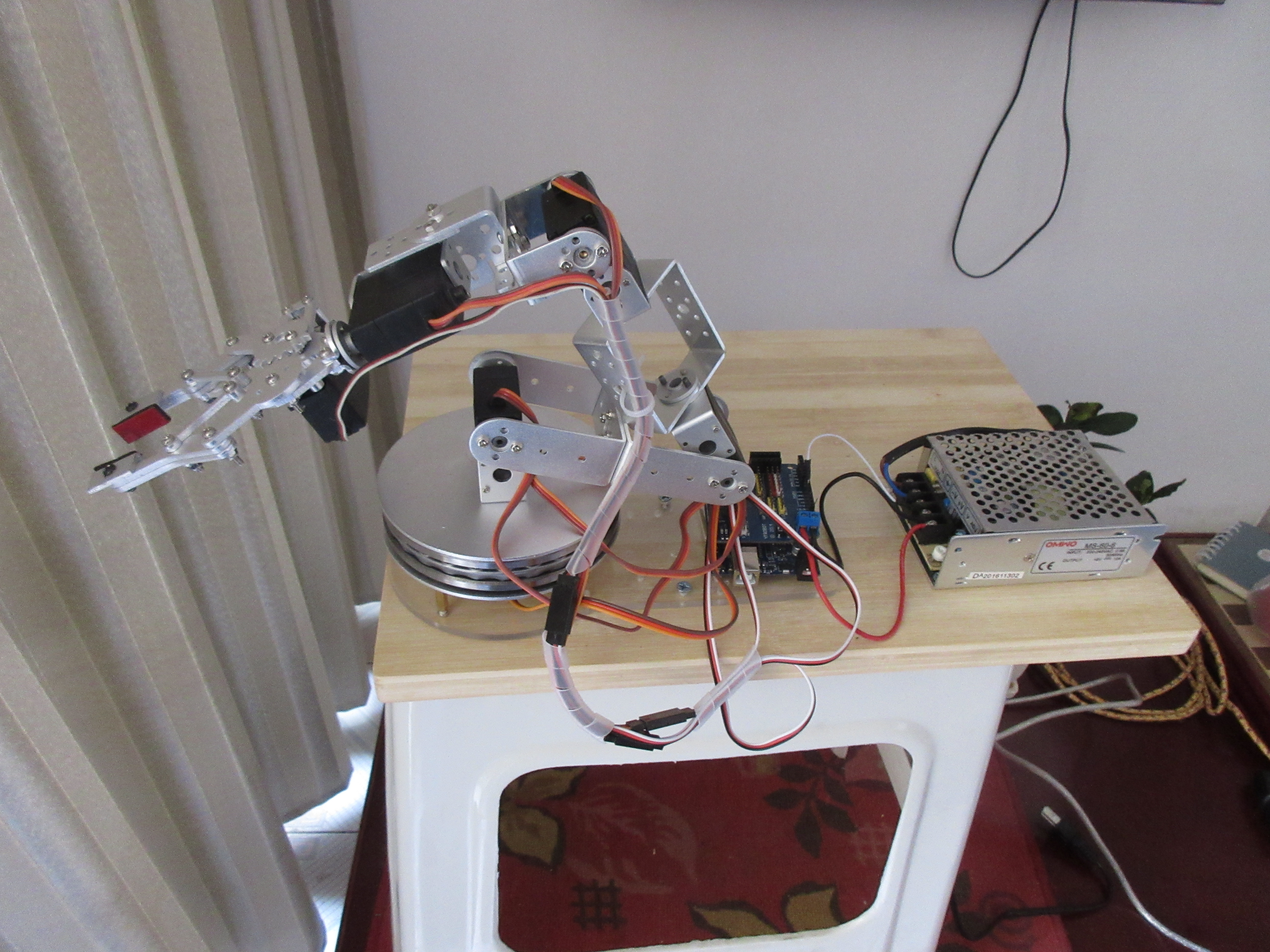
1. When I run the circle() subroutine my robot moves more in an elliptical shape than a circle. I think that is because my servos are not calibrated. I tested one of them and 1500 microseconds was not the same as 90 degrees. Will work on this to try and find a solution. Don't believe there is anything wrong with the algorithm but rather with my settings. Update 2018/2/11 - just discovered this is due to error in the original code. I don't see how his program worked Fixed code using this: float wri_servopulse = 1500 - ( wri_angle_d * pulseWidth ); (original code was adding)
2. Where can I find more information about how the set_arm() function works: Oleg Mazurov's website explains everything or provides links for more info: https://www.circuitsathome.com/mcu/robotic-arm-inv...
3. Is there any boundary condition checking? No. When my robot arm is passed an invalid xyz coordinate it does this funny kind of arching movement like a cat stretching. I believe Oleg does do some checking in his latest program that uses a USB to program the arm movements. See his video and link to his latest code.
4. Code needs to be cleaned up and microsecond code can be done away with.