Use the Switcheroo to Unlock Doors With Your Smartphone
by dangerousthings in Circuits > Electronics
12625 Views, 25 Favorites, 0 Comments
Use the Switcheroo to Unlock Doors With Your Smartphone
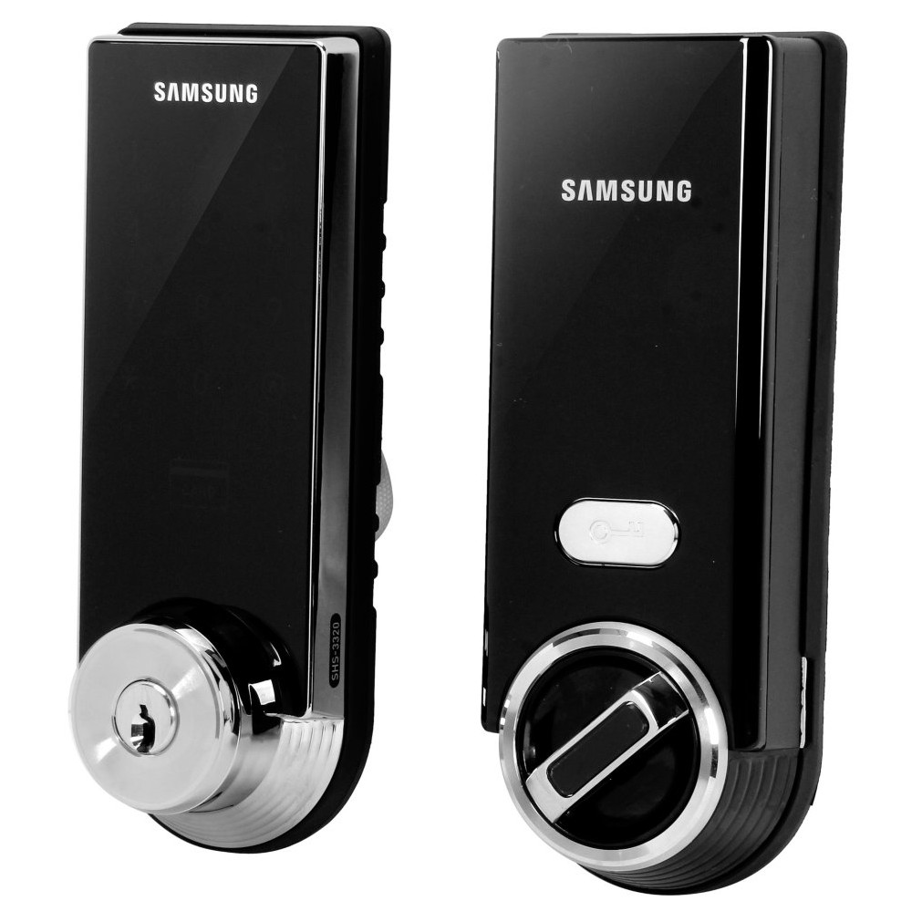
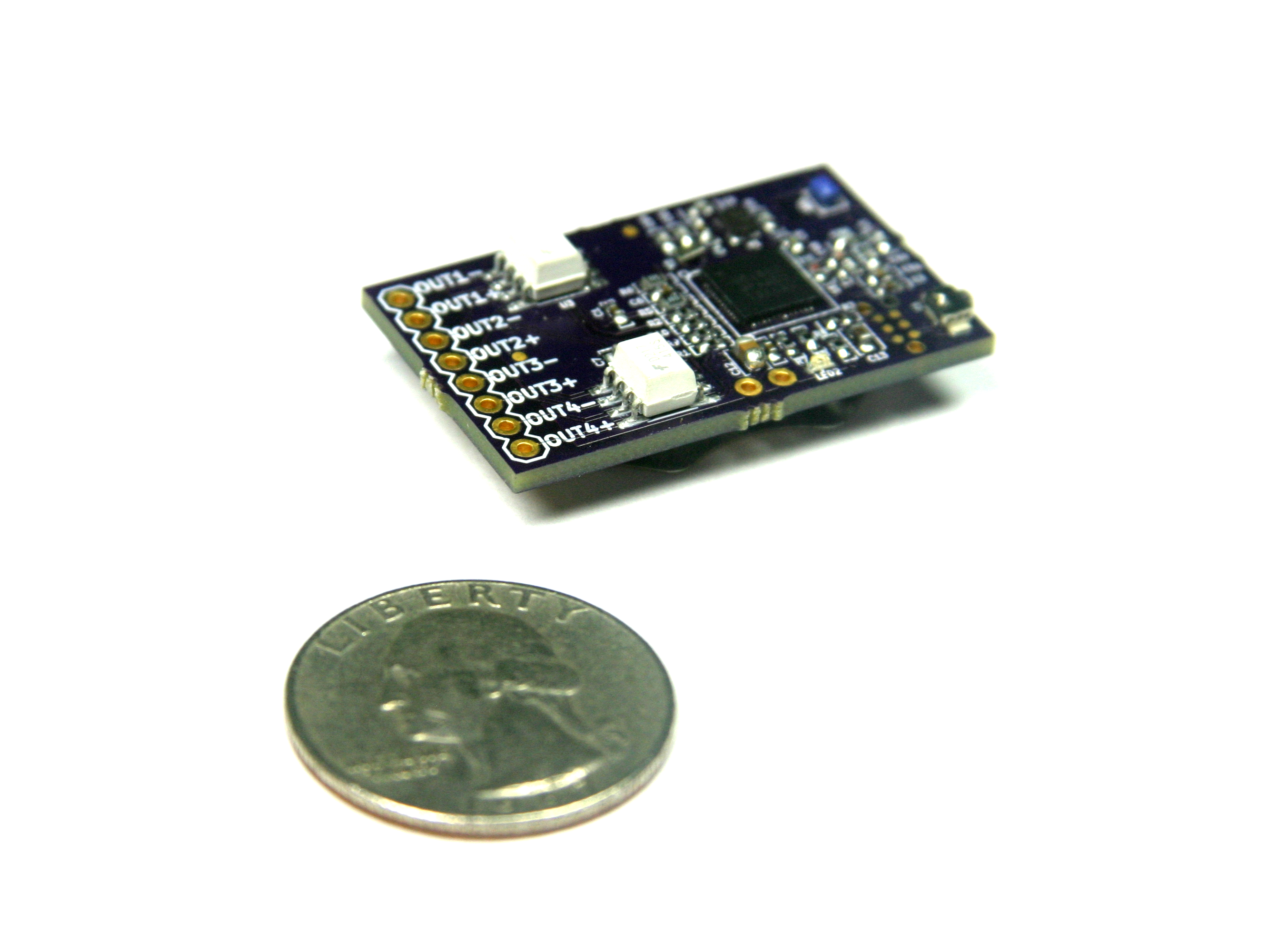
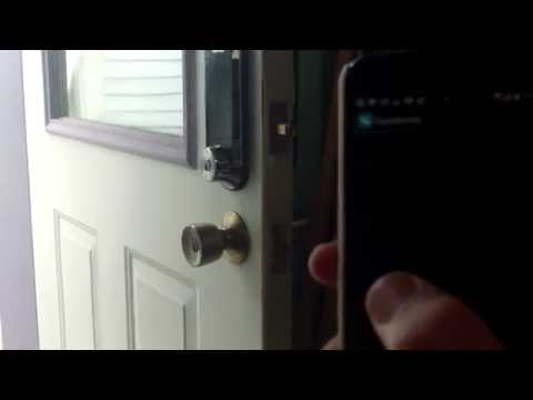
Use the Switcheroo to upgrade an electronic deadbolt so you can open it with your smartphone or tablet! The Switcheroo is a Bluetooth low energy development board that allows your Bluetooth enabled device to control things. Build your own projects or modify existing devices - it's a cinch with Switcheroo!
Many electronic door locks feature a push-button on the inside face which lets you to lock and unlock the door by simply pressing the button. We are going to interface the Switcheroo with that button to enables smartphone control over locking and unlocking the door lock.
Gather Your Tools and Materials!
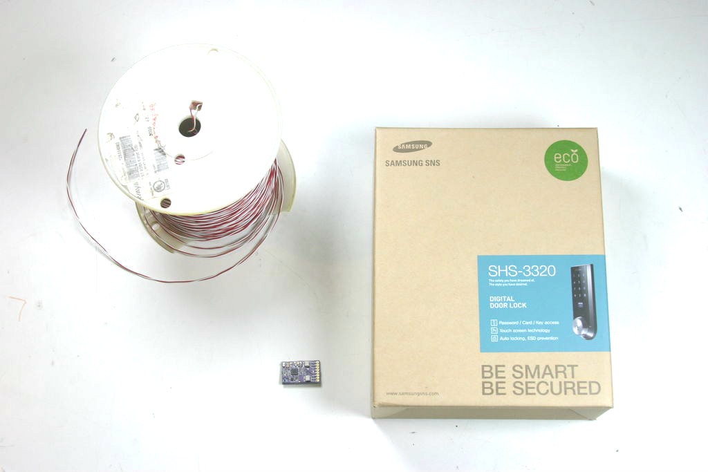
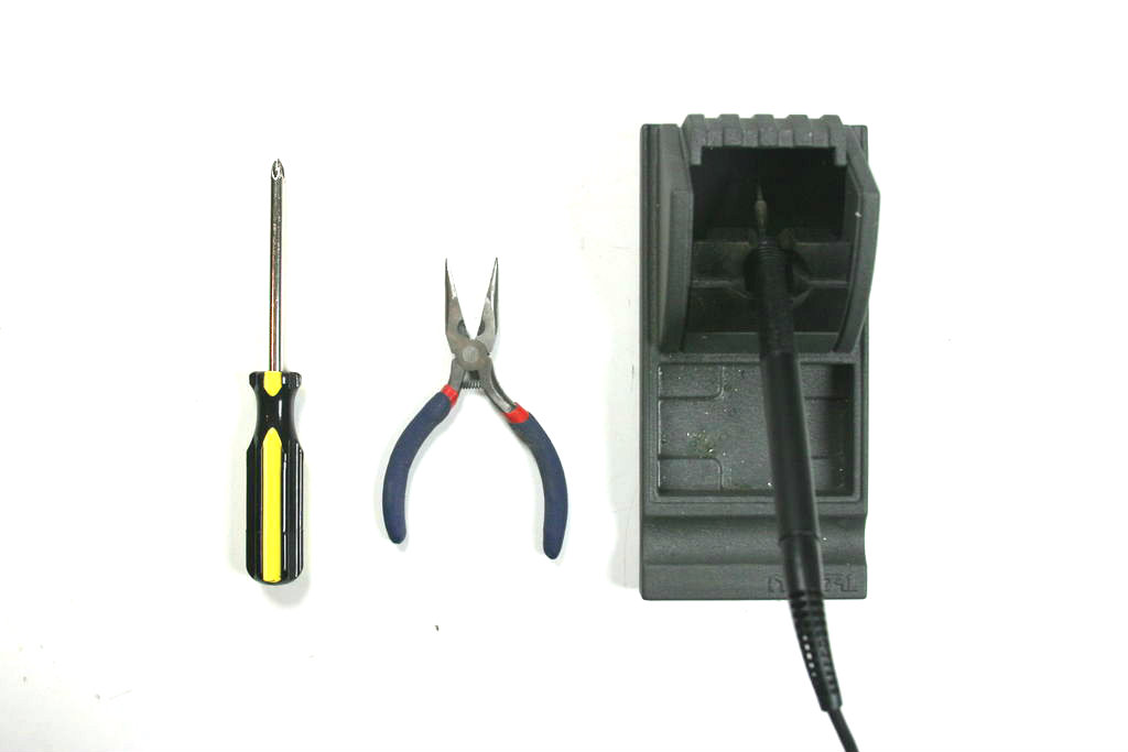
You won't get very far without the right gear. For this project you will need;
- Switcheroo board from www.switcherooboard.com
- At least 2 feet (60cm) of connecting wire (two different colors is better)
- Philips screwdriver
- Needlenose pliers
- Soldering iron & solder
Since the Switcheroo will be leeching power from the Samsung door lock's battery pack, you will need to solder the included 3.3v regulator to the Switcheroo. If you're not sure how to do that, follow these instructions!
Prepare the Samsung Ezon Door Lock
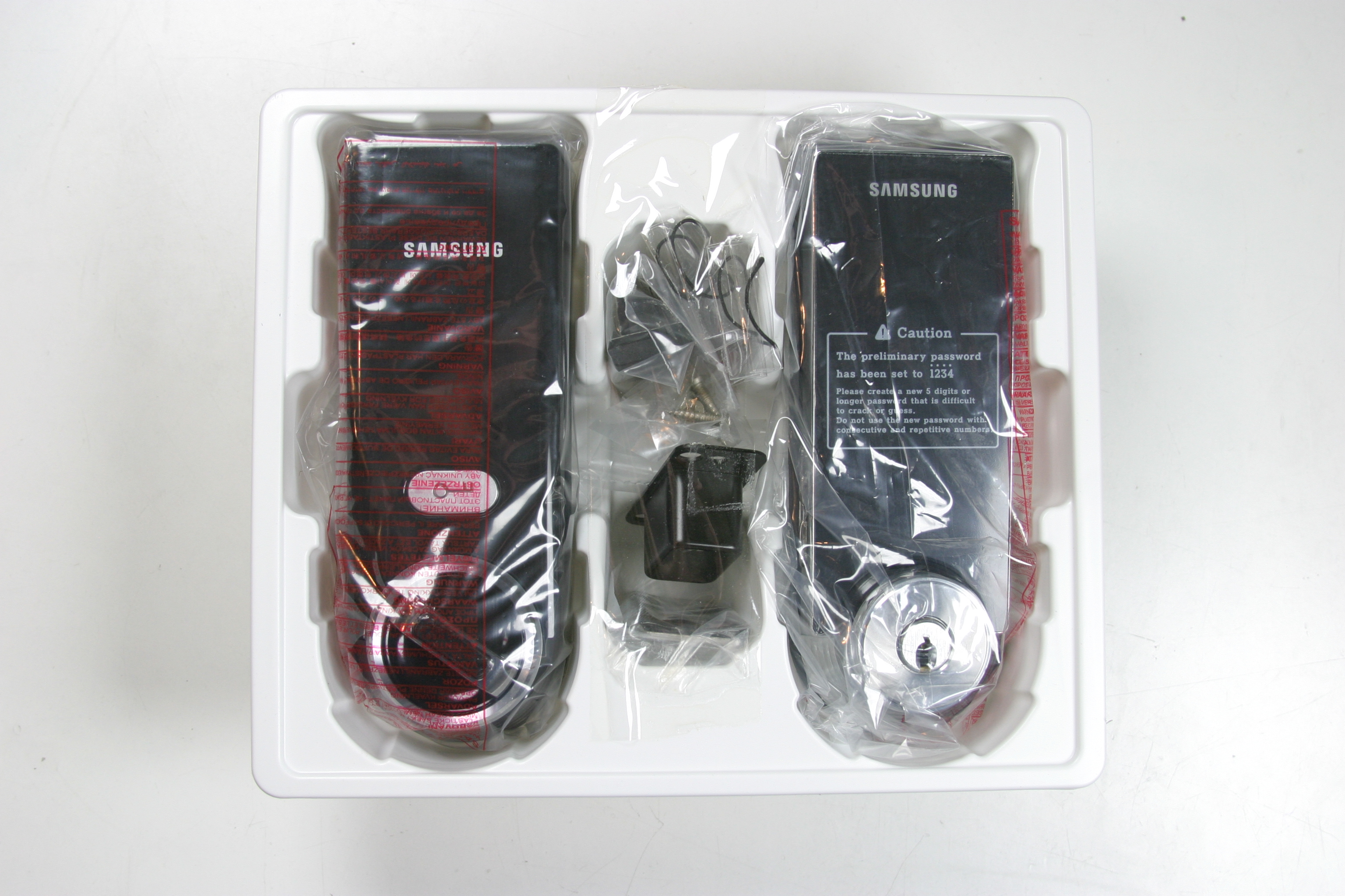
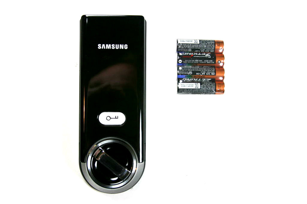
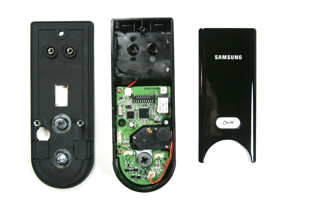
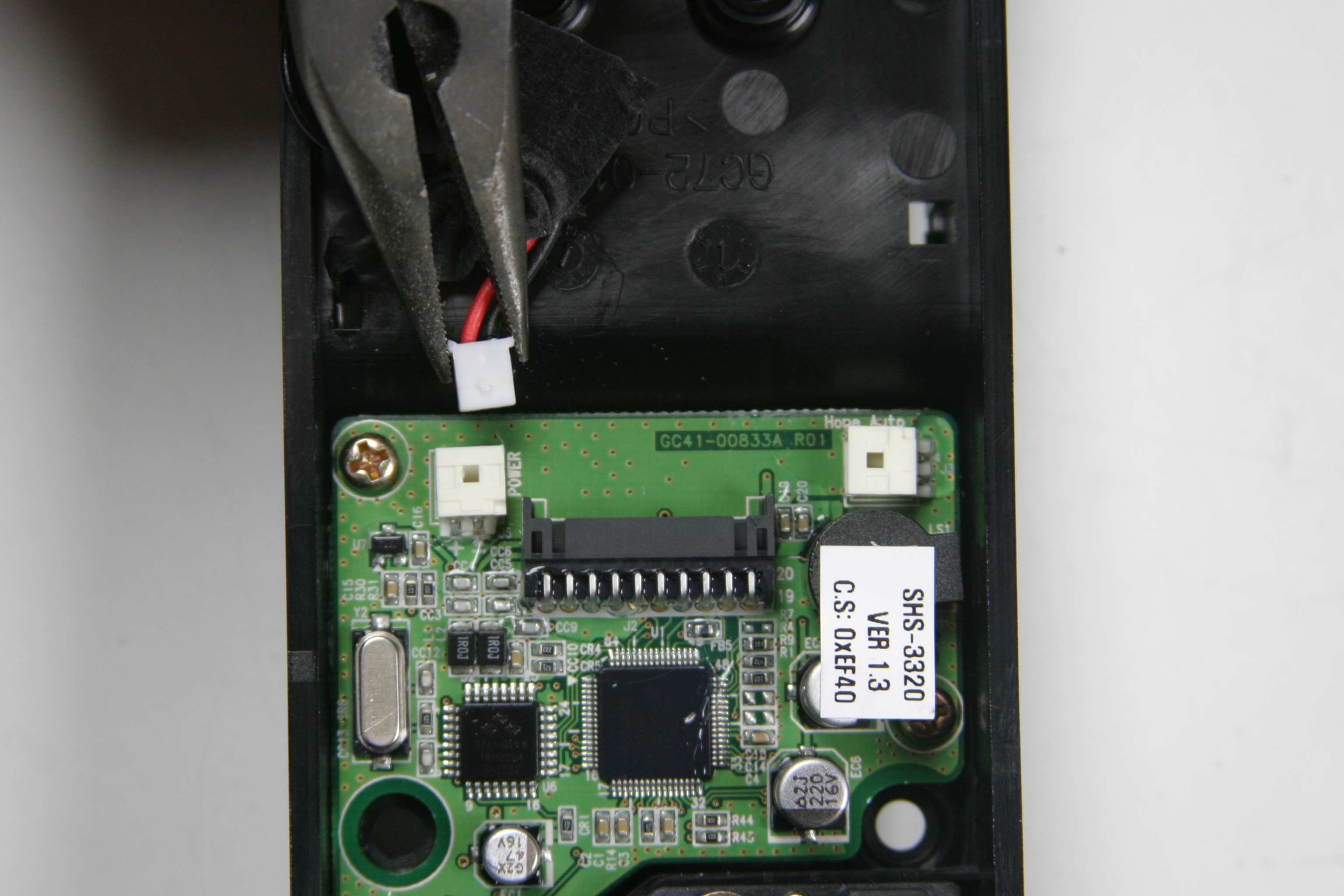
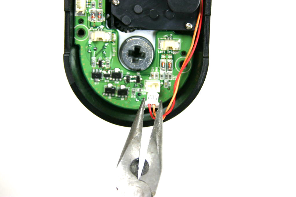
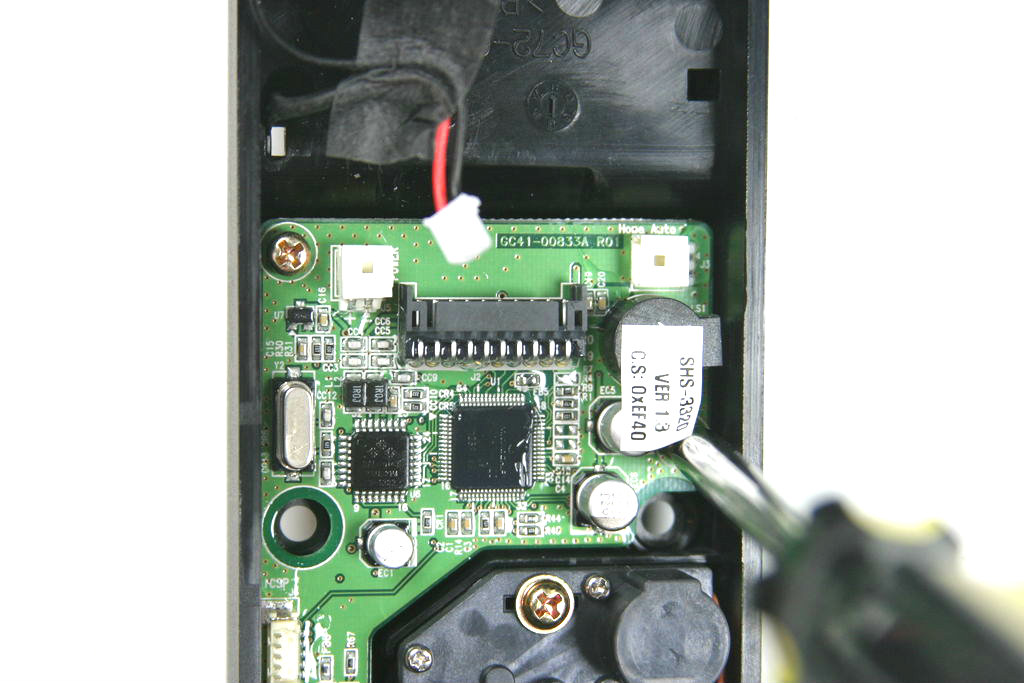
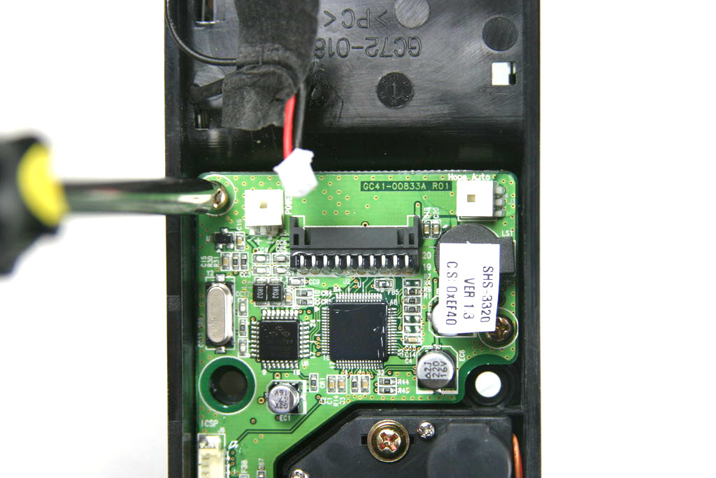
- Take the lock out of the box. Slide the cardboard insert out of the box to get at the good stuff. You don't need to do anything with the external lock face, just remove the part of the lock that goes on the inside of the door from the left side of the box and put it on the table in front of you.
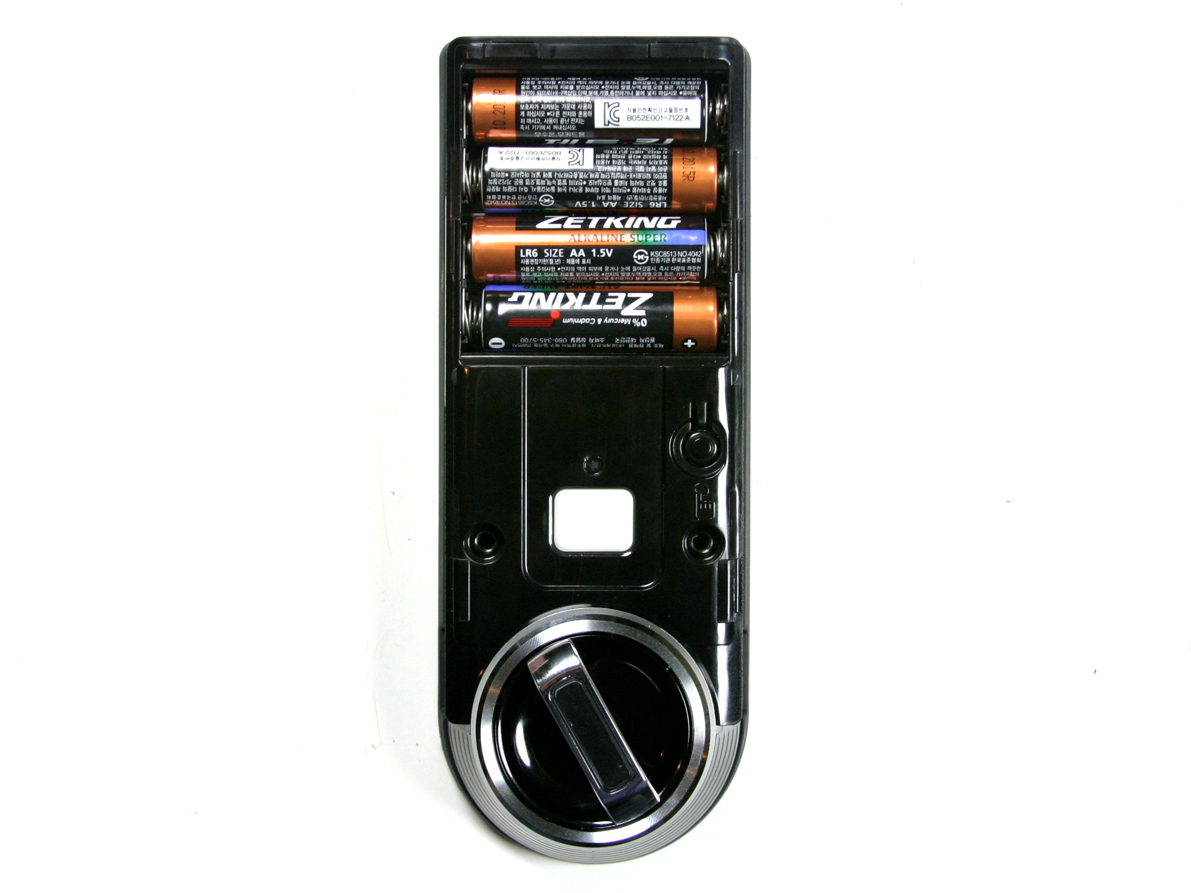
- Remove the battery cover from the lock, then remove the door plate from the back of the lock.
- Using the pliers, disconnect the power supply wires that lead from the battery box to the upper left-side of the lock control PCB. If you're thinking to yourself "pfft, pliers... I'll just use my fingers", yeah, that's what we thought too... it resulted in broken wires and a soldering job to fix. Just use the pliers.
- Again with the pliers, disconnect the lock motor supply wires from the bottom of the lock control PCB.
- Using your Philips screwdriver, remove all 4 PCB mount screws. Yes, there are 4 of them... one might be hidden sneakily under an adhesive label that rests over the piezo speaker assembly.
- Pull the PCB free from the lock assembly, being careful to leave the motor control plate that sits under the PCB in place. Just leave the lock face down on the table when you remove the PCB... don't overturn the lock to drop the PCB out because motor components will follow after it, and they are covered in some kind of skunk-juice grease that will stink up the place, and cause "icky finger" syndrome when you pick up all the loose greasy motor bits up off the floor.
Get to Modding!
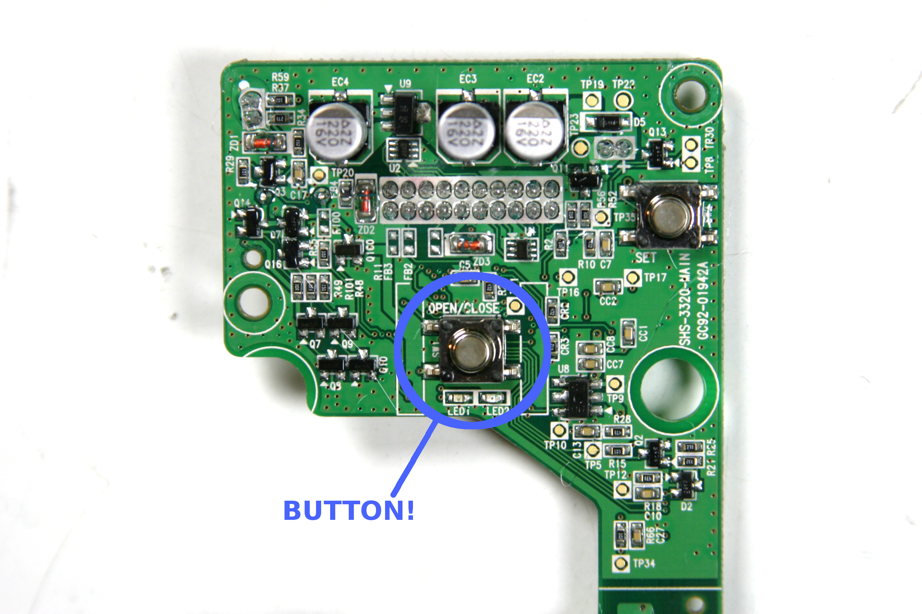
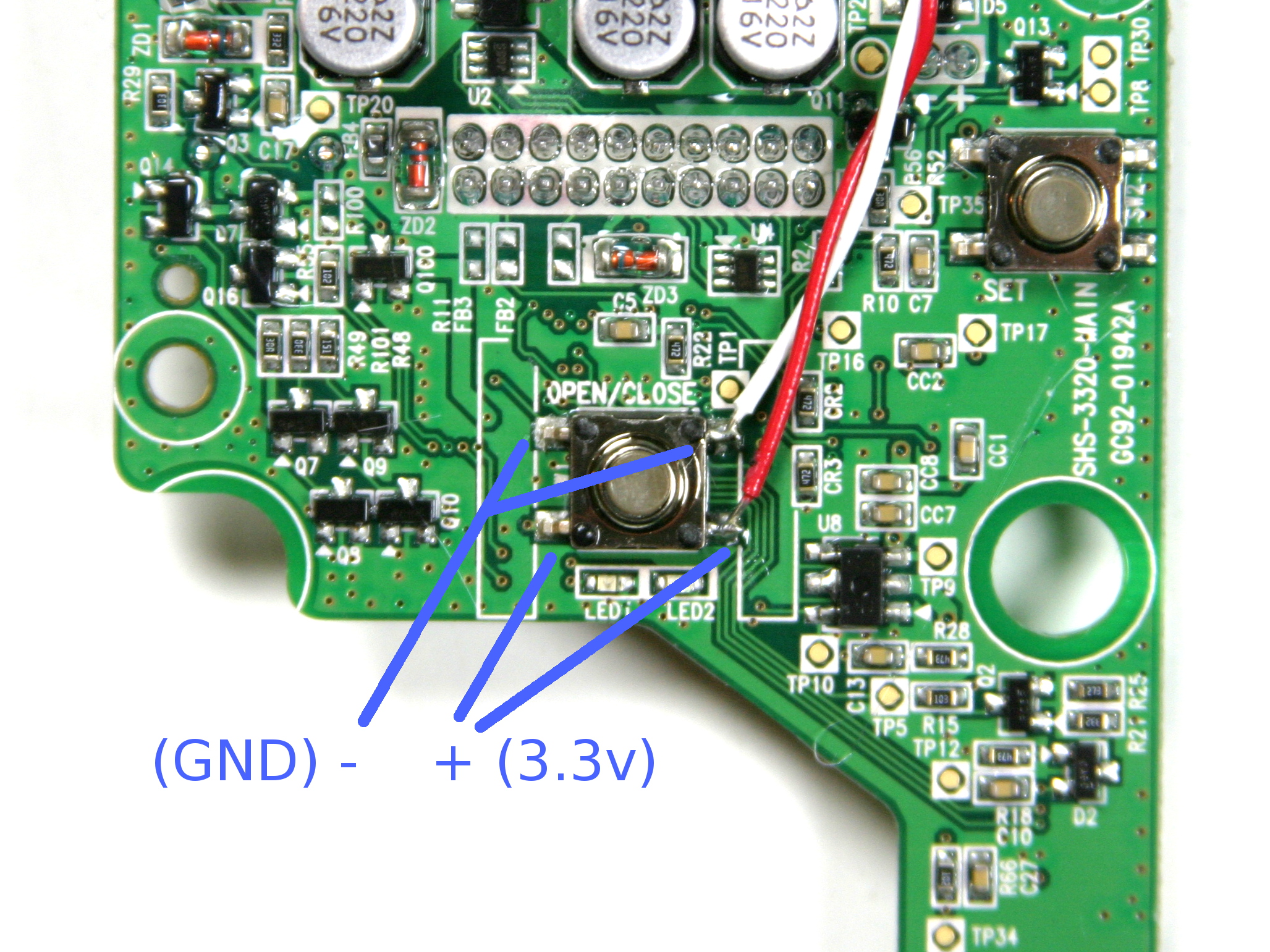
The Samsung Ezon deadbolt lock is nice because it has a "open/close" button on the lock face which allows a person standing on the inside of the door to lock and unlock the deadbolt just by pressing a button. You're going to interface the Switcheroo with that button so you can "press" it using your smartphone!
The Switcheroo uses opto-isolators to control things, and opto-isolators are polarized. Pretty much every device you encounter that has a button on it will use a switch of some sort inside that connects a circuit which is polarized, meaning one side of the switched circuit is + (positive DC voltage) and the other side is - (ground). Of course, this only applies to DC devices, and in no way should you try to connect the Switcheroo directly to an AC circuit of any kind.
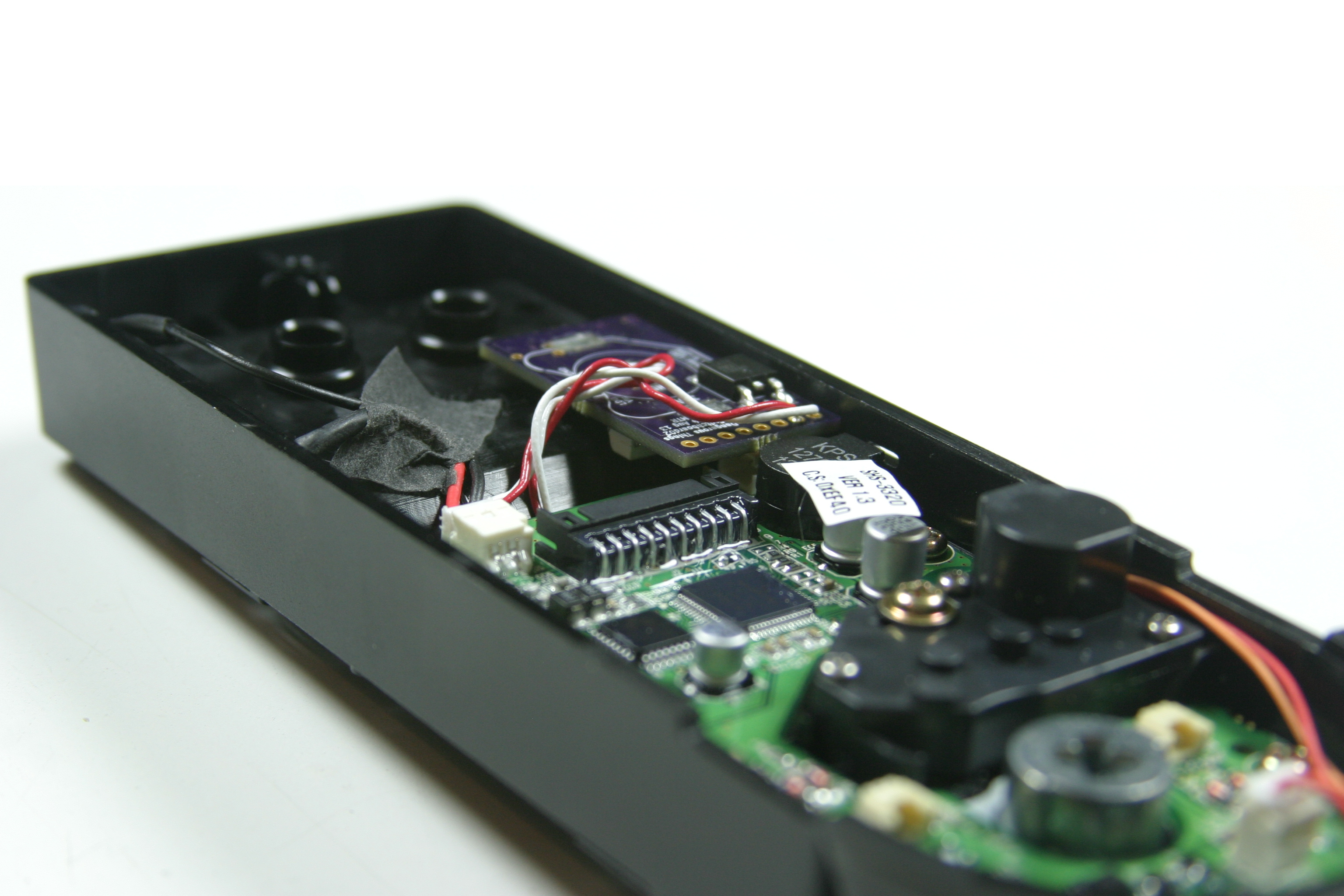
The open/close switch on the PCB is polarized such that the top pads (leads going to the switch) which are situated just under the words "OPEN/CLOSE" silkscreened on to the PCB are the ground pads, and the pads on the bottom of the switch are polarized at 3.3v DC. If you have multi-color wire, choose one color to be the ground side and one color to be the positive DC side, then solder that wire to the switch pads as shown. If you don't have multi-color wire, be sure to mark which wire is the positive wire.
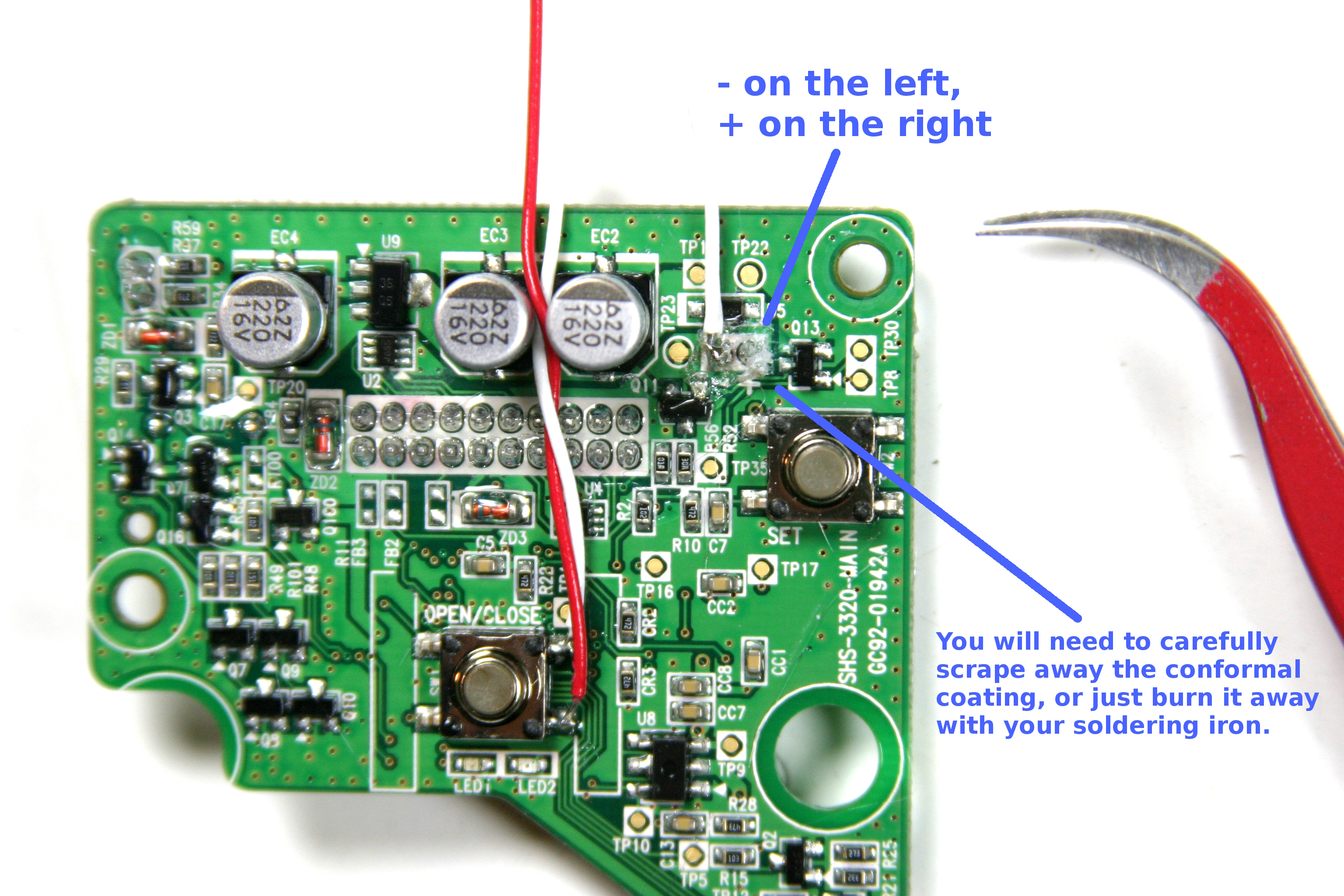
Now you need to get power for your Switcheroo. Assuming you've already soldered the optional 3.3v regulator to your Switcheroo board, you just need to borrow power from the Ezon's battery pack. There is a challenge here though...
The people who make the Ezon lock almost completely cover the lock control PCB in a special coating to protect it, which is really nice of them to do, but it makes fiddling with stuff a little more difficult. You'll be soldering supply wires to the back side of the through-hole two-conductor wire socket that the battery pack plugs into, and you'll need to either carefully pierce and scrape away the conformal coating material from those solder joints, or you can choose to burn through the conformal coating material with your hot soldering iron. Either way has its challenges, but poking the PCB with sharp things could lead to... issues. If you have doubts about your dexterity, well you probably shouldn't be handling sharp things or hot soldering irons, but I'd go with the "burn through it" approach as you're less likely to damage the PCB that way.
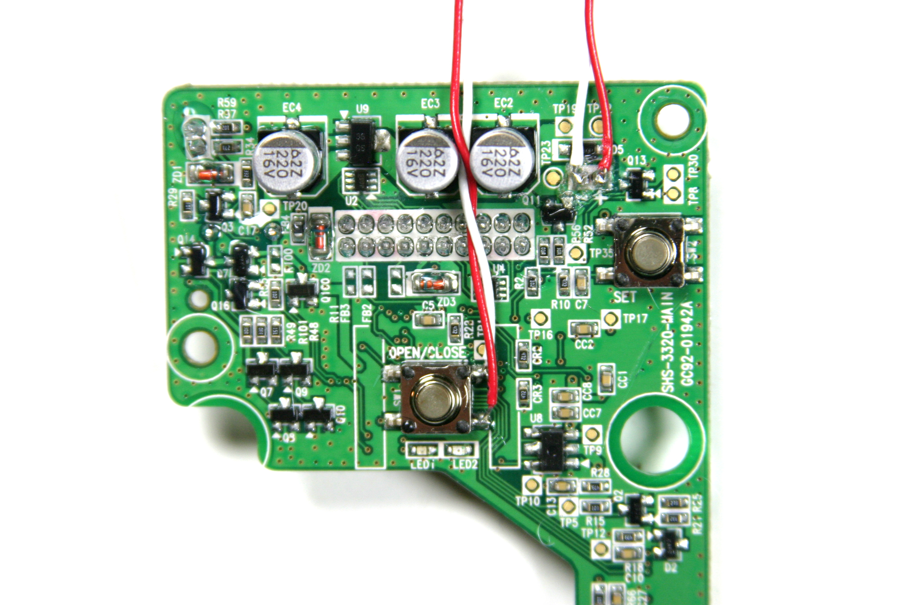
Ok, we'll just assume you made it through that part and you now have 4 wires soldered to the lock control PCB - two for switch control and two for power. Nice job you!
Connect the Switcheroo!
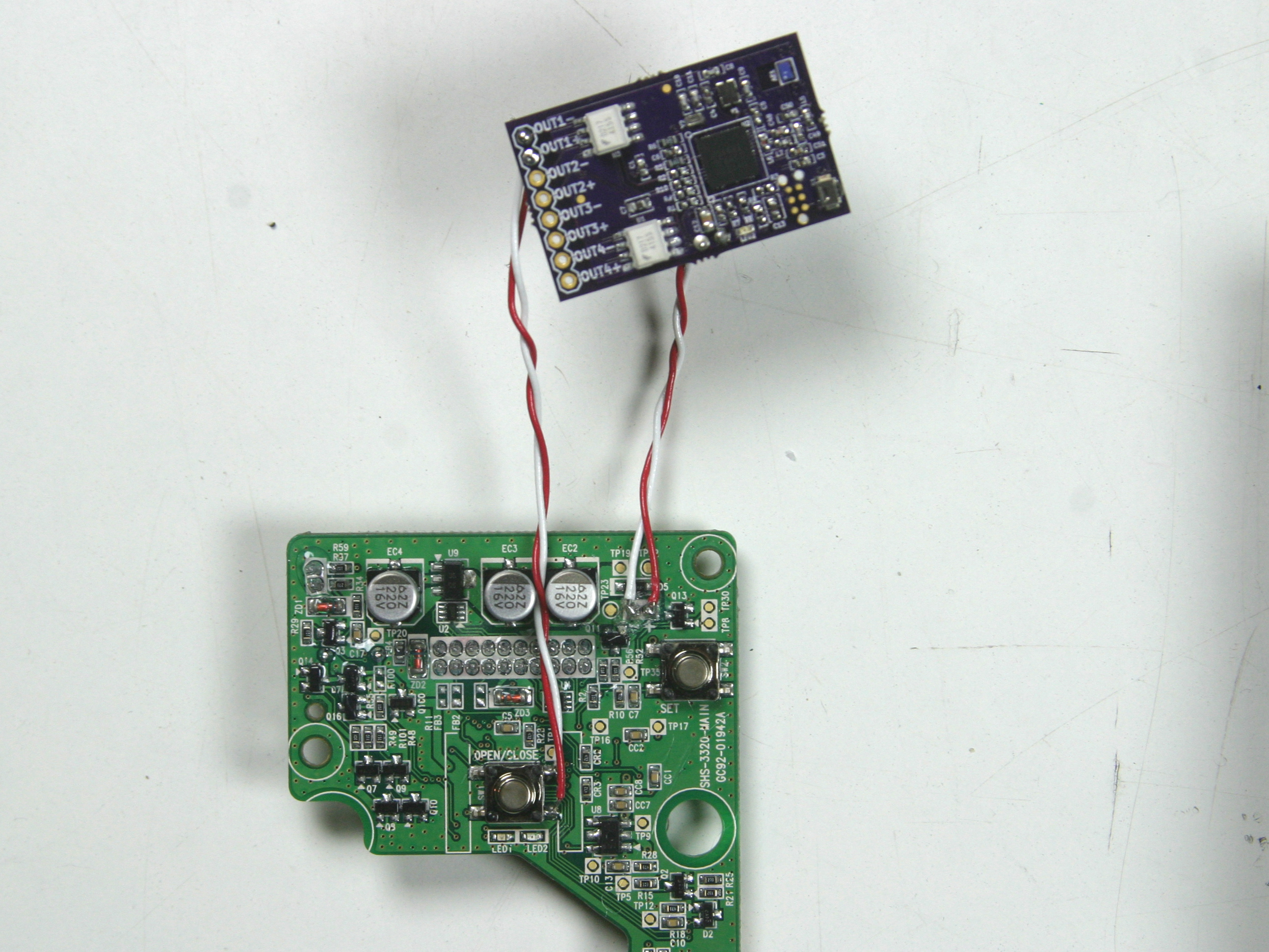
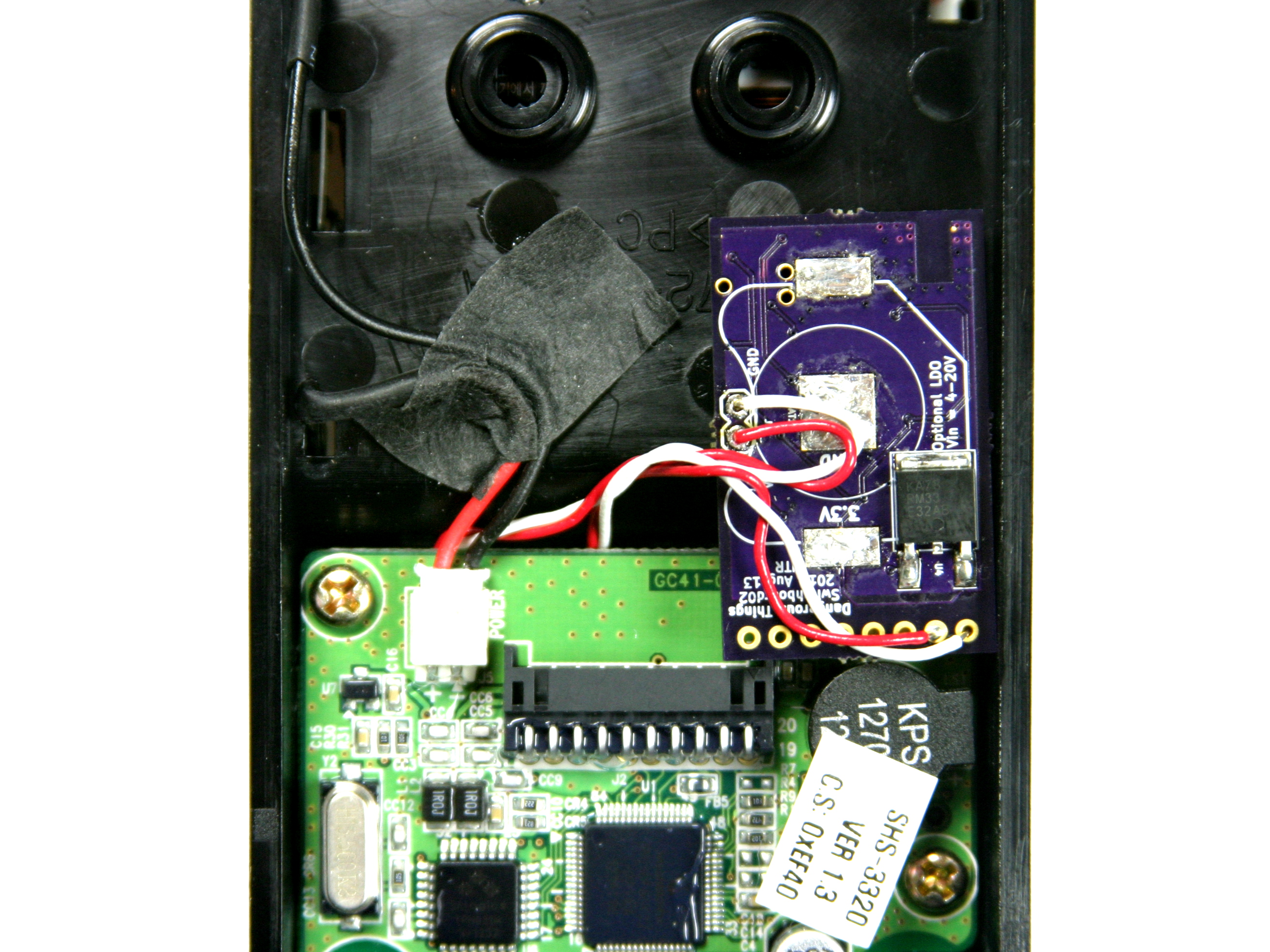
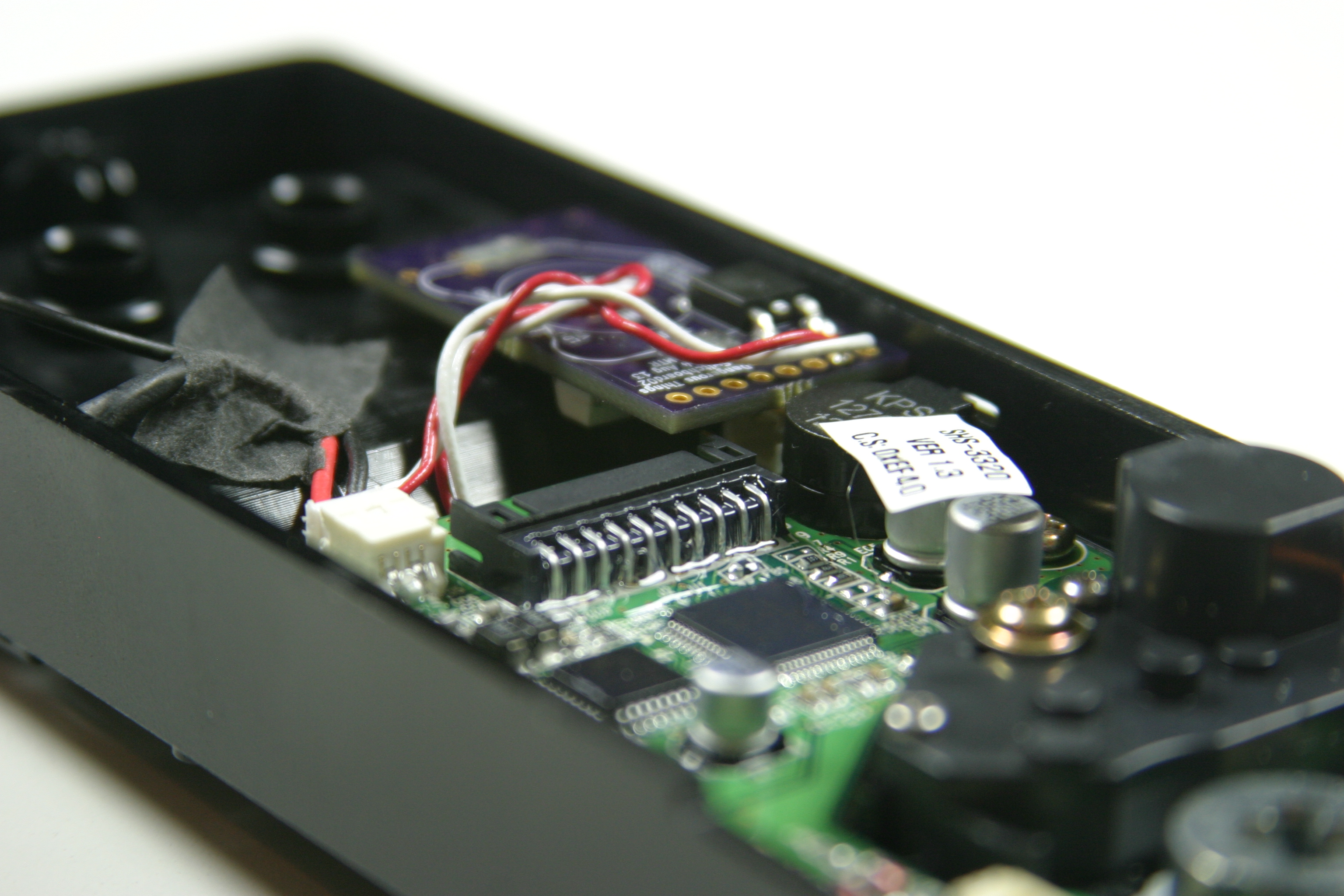
At this point you're basically out of the woods. The last part is easy...
- Choose one of the 4 outputs on the Switcheroo board. Let's go with output 1.
- Solder the - (gnd) side of the switch pair to the - (gnd) pin of output 1
- Solder the + (positive) side of the switch pair to the + side of output 1
- Solder the + (positive) power supply wire to VIN source pin on the Switcheroo
- Solder the - (gnd) power supply wire to the - (gnd) pin on the Switcheroo
Be sure to solder the wires up from the bottom of the Switcheroo, because you will be flipping it over to nestle it snugly inside the Ezon case.
Once you've got the Switcheroo all connected up, place it and the PCB back into the internal lock face. Re-insert the screws to secure the PCB, then re-attach the power supply and motor supply wires to the PCB.
Now that the Ezon is back together, flip the Switcheroo board over so the opto-isolators are facing down into the plastic case and snuggle that lil buddy up next to the piezo speaker. It'll fit just perfect in that corner, and there isn't any worry about shorting or anything!
Put the rubber covered door plate back in place and you're all set. Install batteries and load up the Switcheroo app on your phone to test!