Use a Light Box to Photograph Professional Looking Pictures of Electronics and PCBs
by kevinjpower in Design > Photography
912 Views, 5 Favorites, 0 Comments
Use a Light Box to Photograph Professional Looking Pictures of Electronics and PCBs
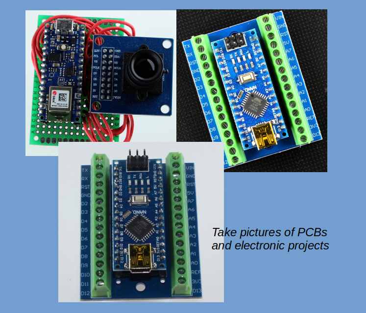
Have you ever wondered how the pictures of PCB’s and electronic components on websites such as eBay, Amazon, Sparkfun or Adafruit are taken? Have you ever taken pictures of your own electronic projects and been disappointed with the results?
This project will show how to make a light box and then use it to take pictures of PCB’s or electronic projects that look as good as the professionals. The results are amazing.
This project uses 120 V connections. Do not attempt unless you are comfortable working with these voltages
Supplies
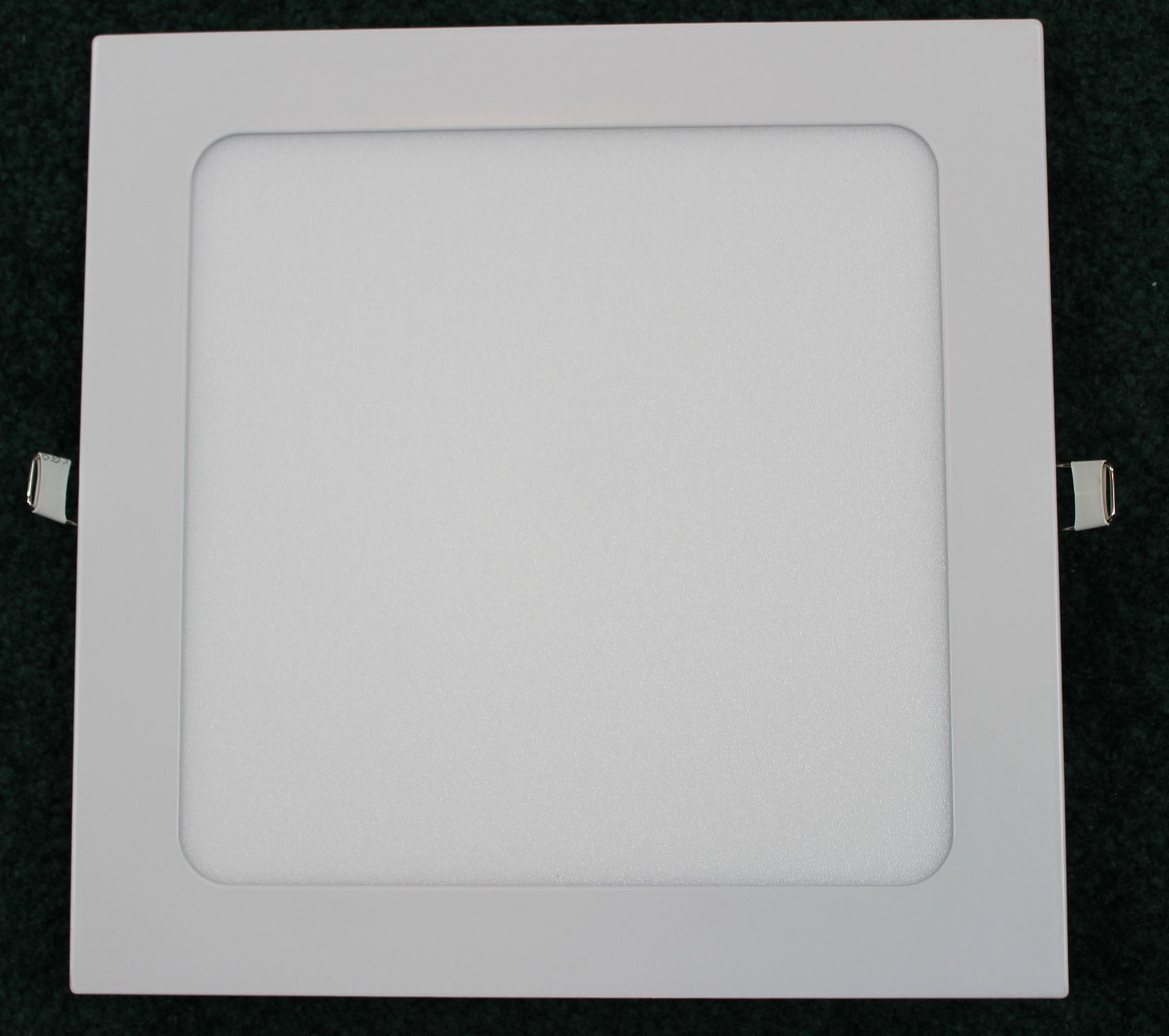
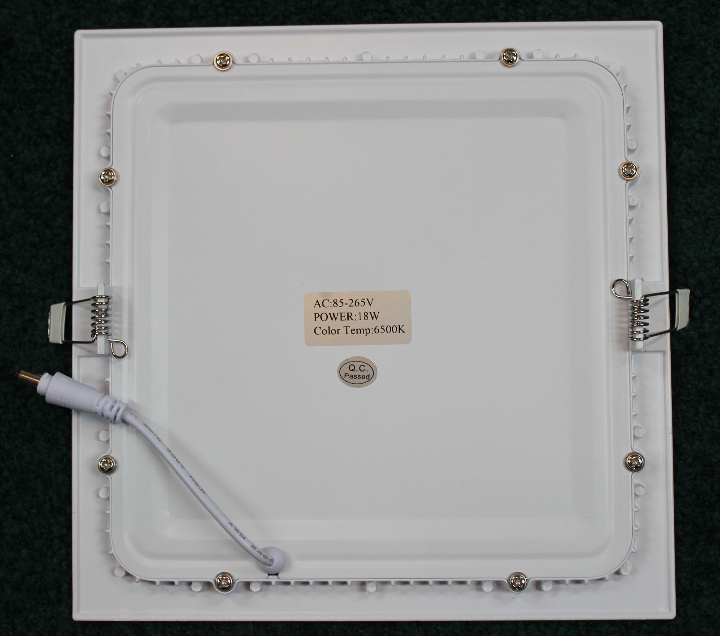
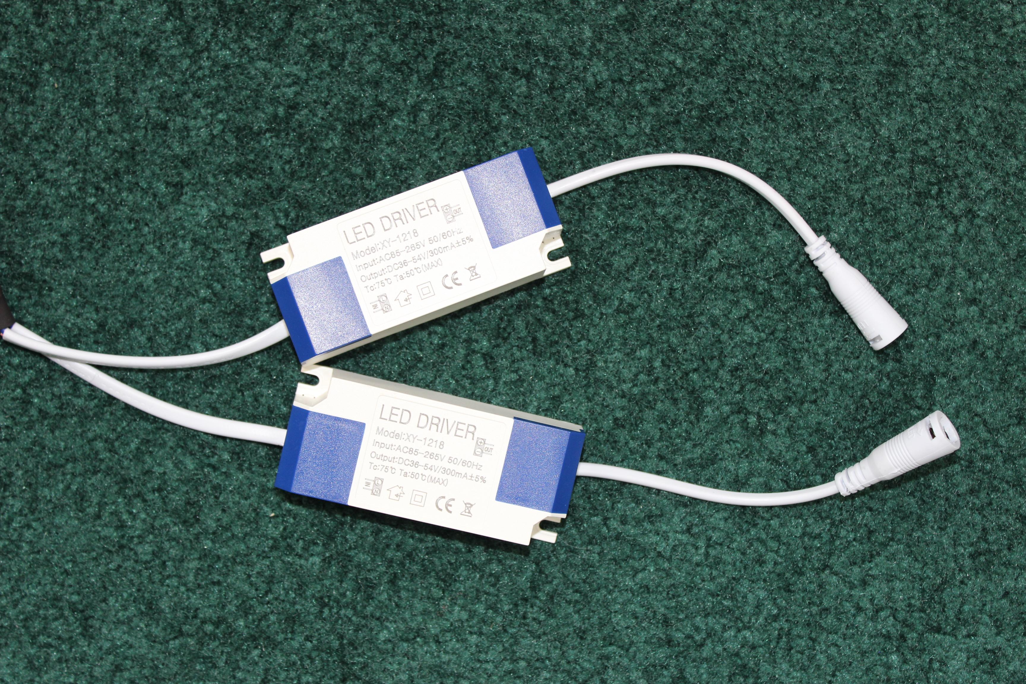
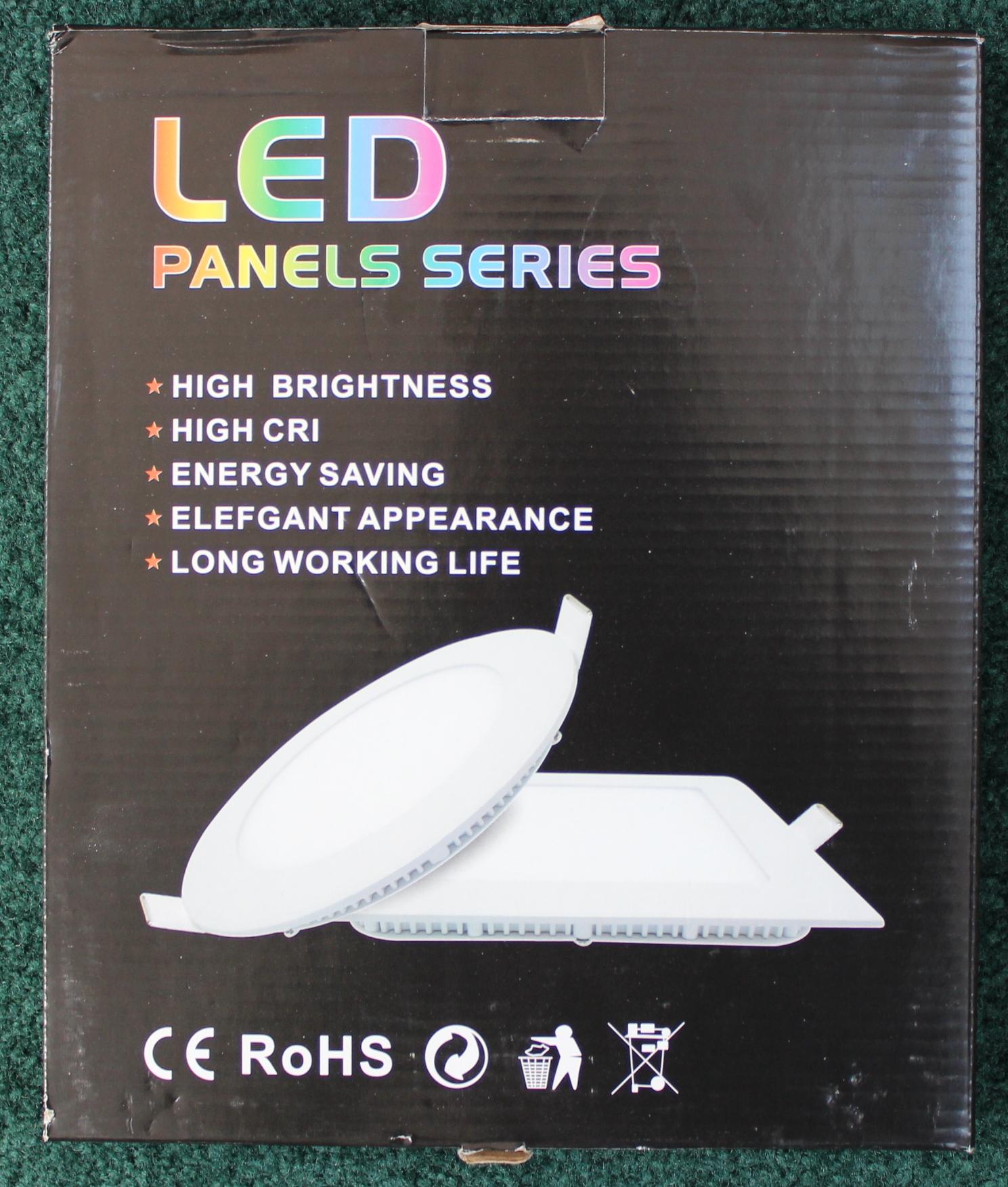
The crucial component of the light box (and the only component I bought), are the square panel LED lights. These are available on Amazon, eBay, etc. They come in various shapes and sizes; the ones I used were 8 inch square LED lights with the overall dimensions of the panel been 9 inch x 9 inch. The light is designed for recessed mounting in ceilings or walls and includes two LED driver boxes.
See the photographs of the unit.
For this project, I removed the clips and springs that are used to hold the light in place. Cut off the clip and remove the spring with a needle nosed pliers.
Other lights could be used. There are also outdoor versions available which would give the same result.
Balance of the supplies below:
- ¾ inch white melamine shelving (I had some off cut pieces in my workshop)
- ¼ inch plywood (again, I had some off cut pieces in my workshop)
- 120 V rocker switch
- Wood screws
- Machine screws (I used #8-32 x 1)
- Connection wires and heat shrink tubing
Cut the Boards
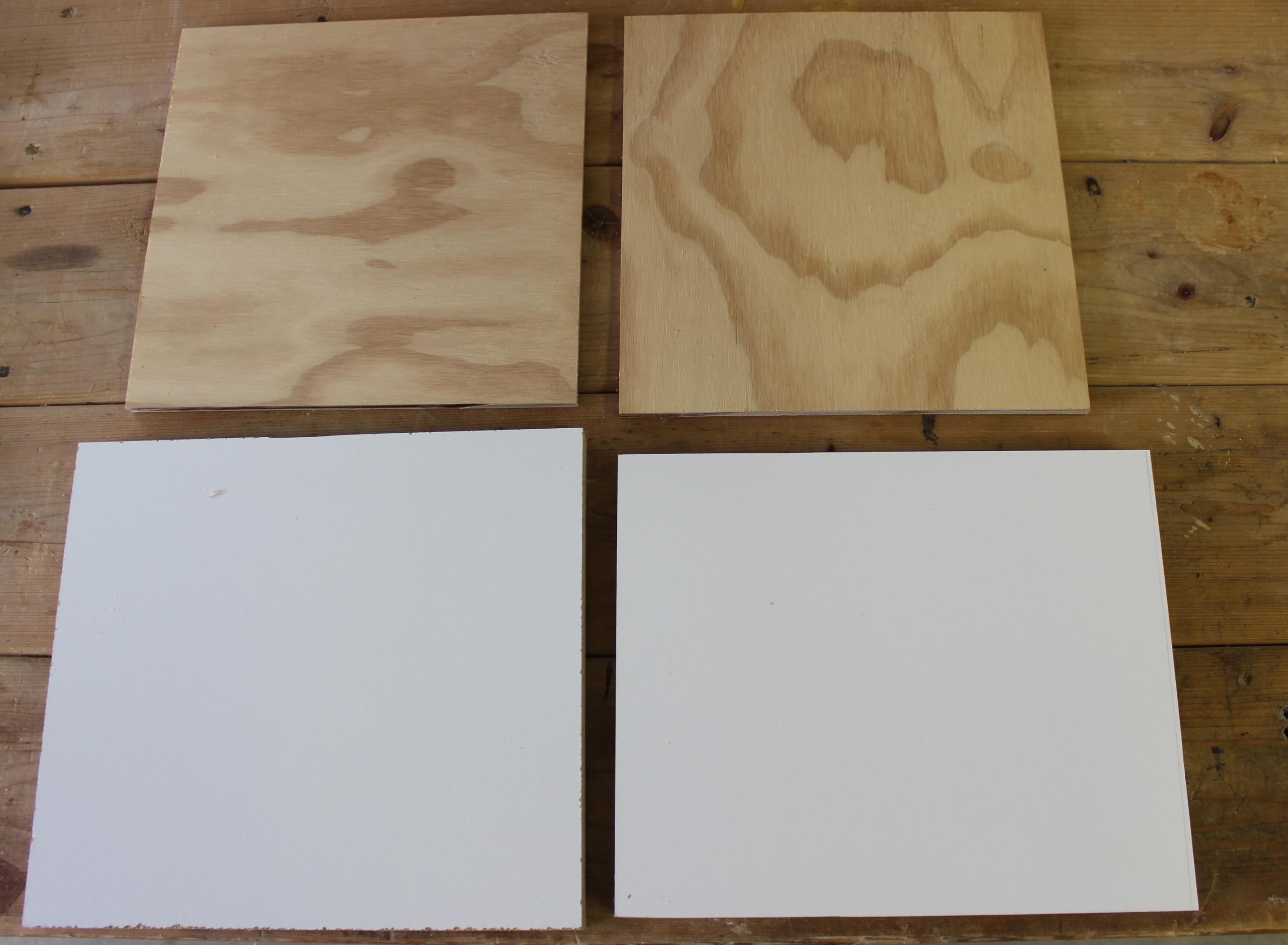
Four pieces of board are needed:
- 2 no 9 ¾ inch x 9 ¾ inch pieces of plywood
- 1 no 9 ¾ inch x 10 ¾ inch melamine
- 1 no 9 inch x 10 ¾ inch melamine
They can be cut on a table saw, with a circular saw or jigsaw.
Assemble the Side Panels
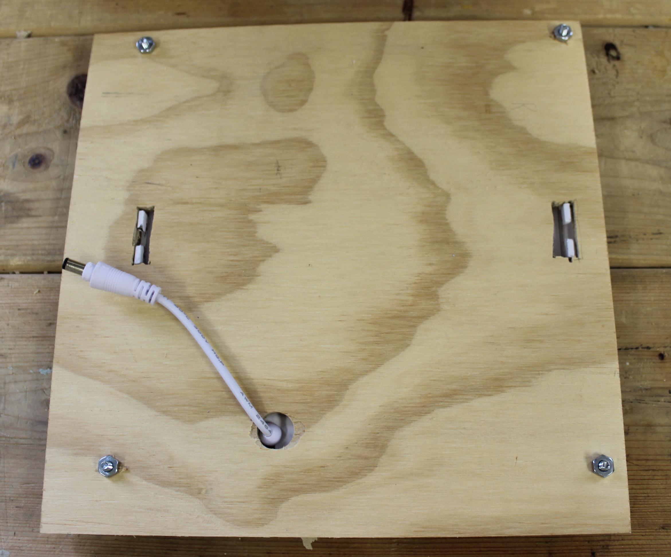
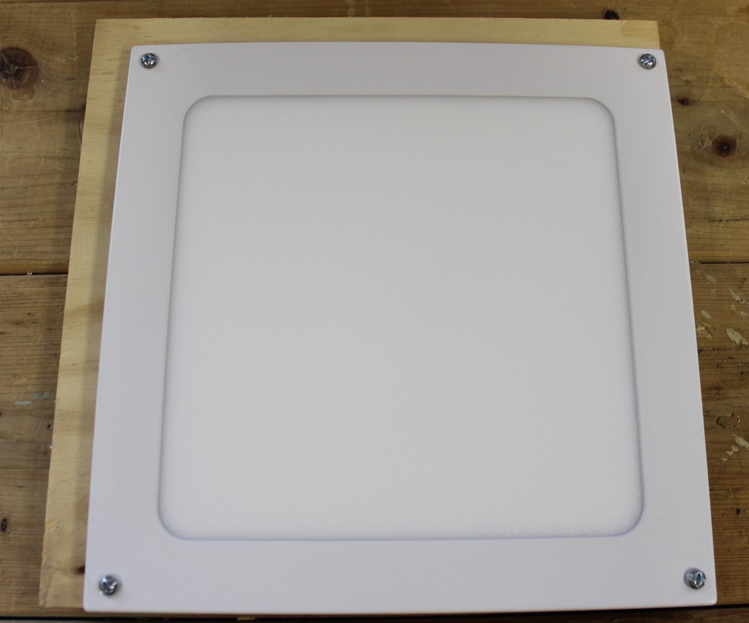
Use the following steps to assemble the side panels of the light box:
- Drill four holes in each of the LED light panels, of sufficient diameter that the machine screws will fit through them
- The LED panels need to be mounted such that a ¾ inch excess of plywood is visible on two sides of the completed side
- Using the holes drilled in the LED panels, mark corresponding holes in the plywood. Drill four holes of the same diameter as the ones in the LED panel
- Mark a slot in the plywood to coincide with the flanges on the LED panel and remove the wodd in the slot with a chisel
- Drill a hole to allow the LED panel connection pigtail to go through
- Use the machine screws to finish assembly of the side panels of the light box
See the picture for the final result
Assemble the Light Box
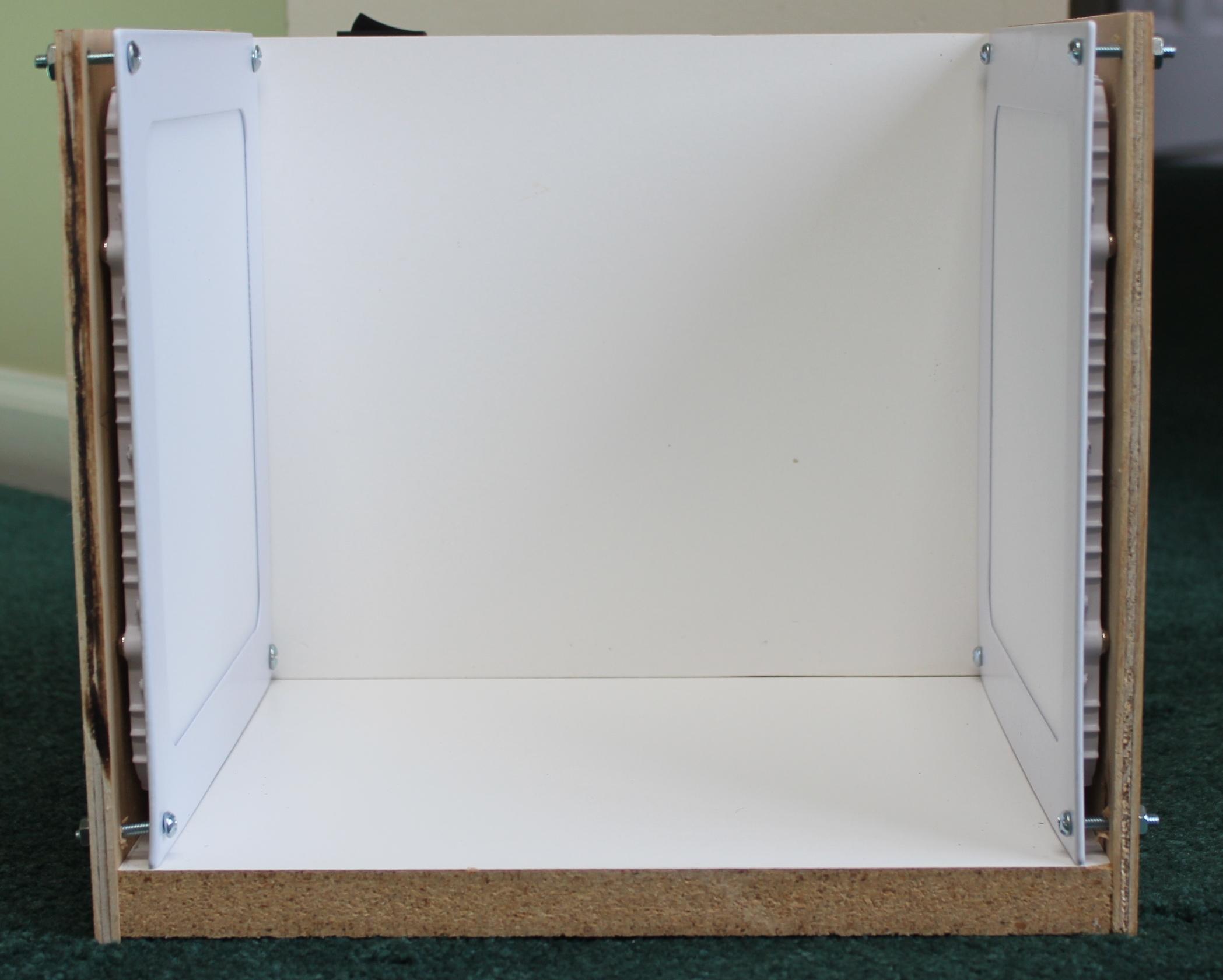
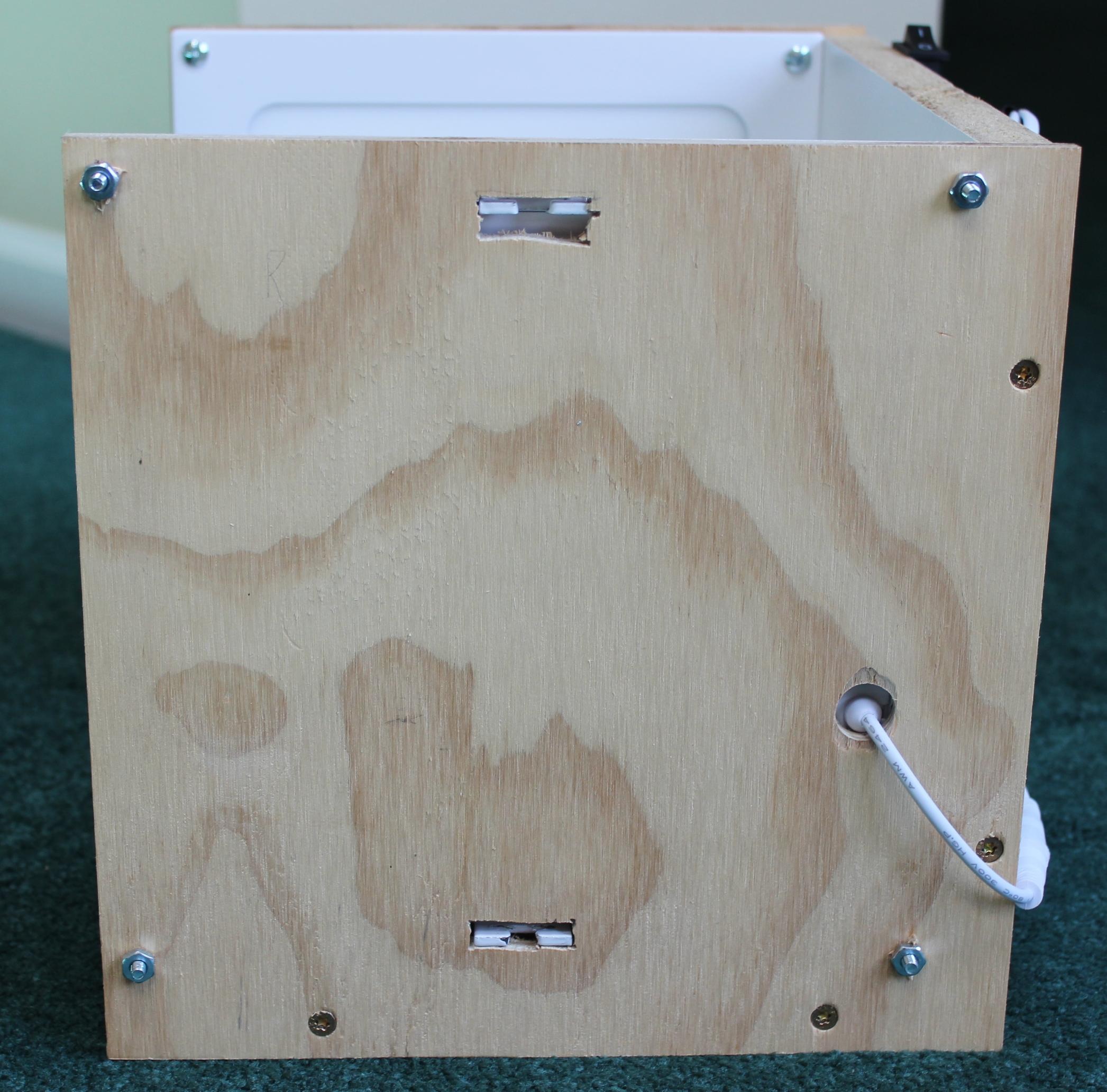
Use these steps to assemble the light box
- Screw together the two melamine pieces, making sure they are at right angles to one another
- Screw the side panels to the melamine pieces to complete the mechanical assembly of the light box
See the pictures of the light box after mechanical assembly
Electrical Wiring
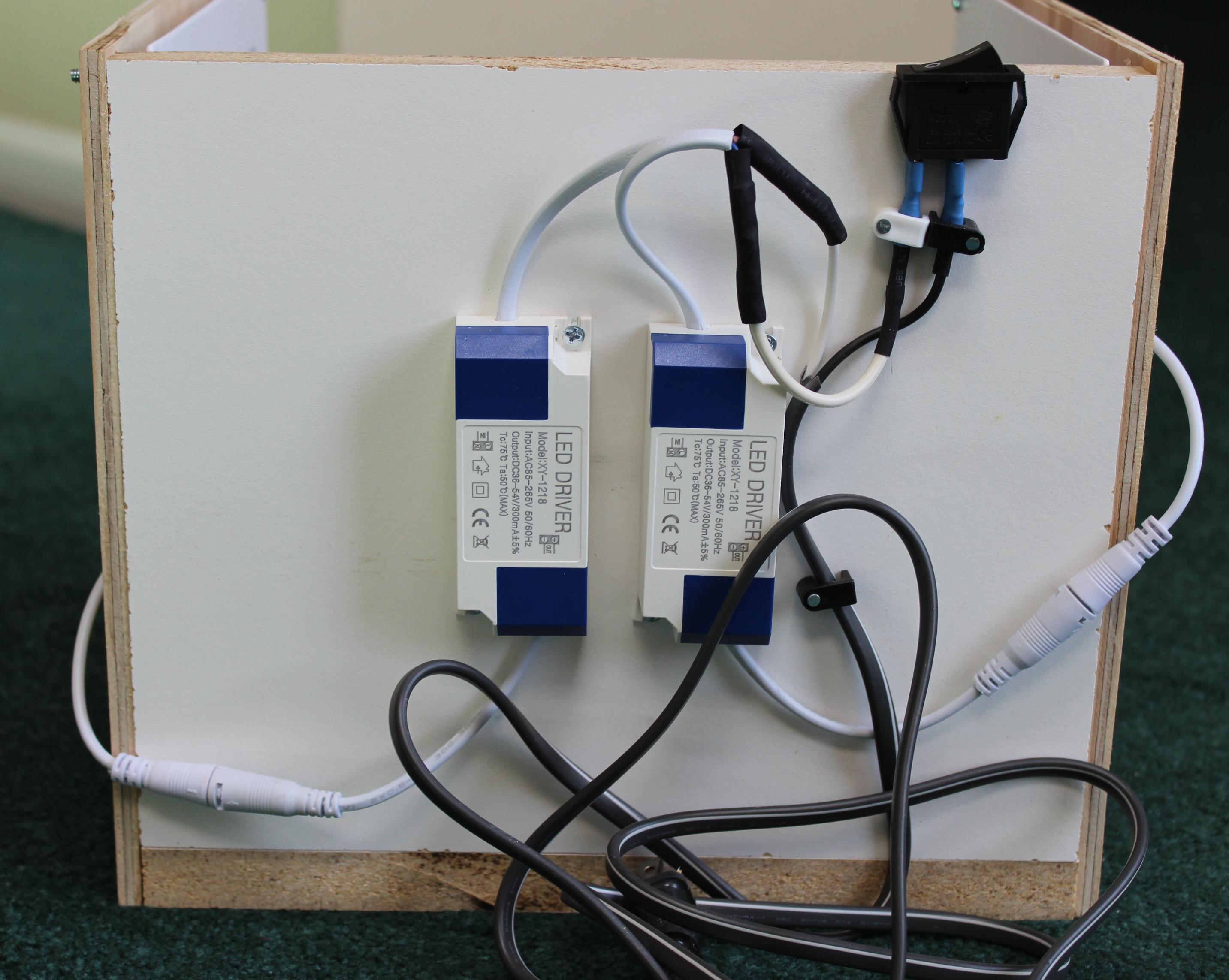
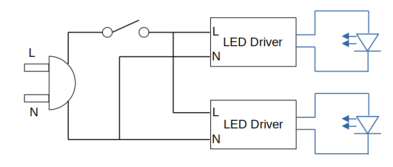
The final step of construction is to complete the wiring. A schematic is included. The 120 V rocker switch must break the live wire from the socket outlet.
The LED drivers can be mounted on the back of the light box and then connected to the pigtails that come from the side panels.
Use insulated straight wire crimp terminals and insulated spade crimp terminals to connect the various items. Heat shrink is necessary to insulate the connections.
See pictures for the completed wiring and finished light box. It is now ready for use
Taking Pictures
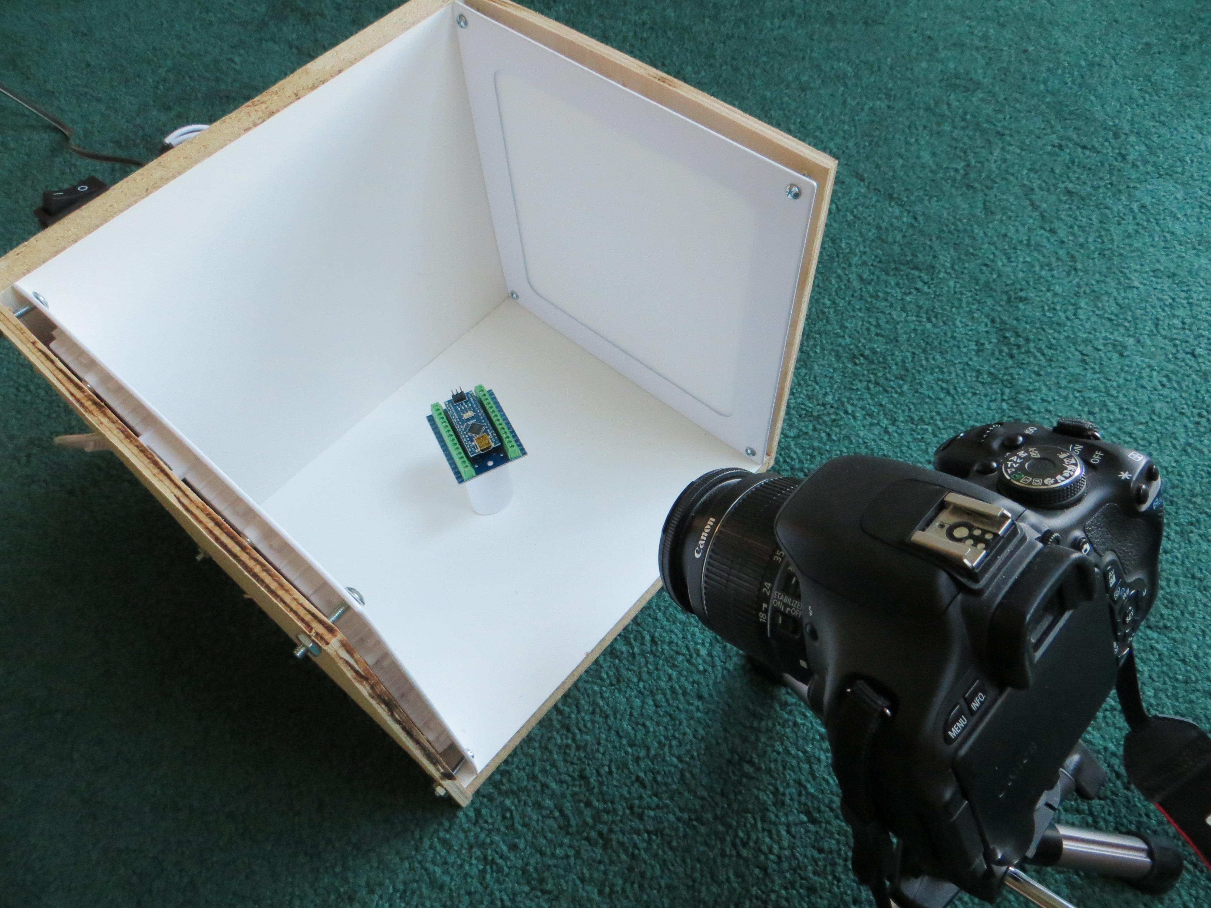
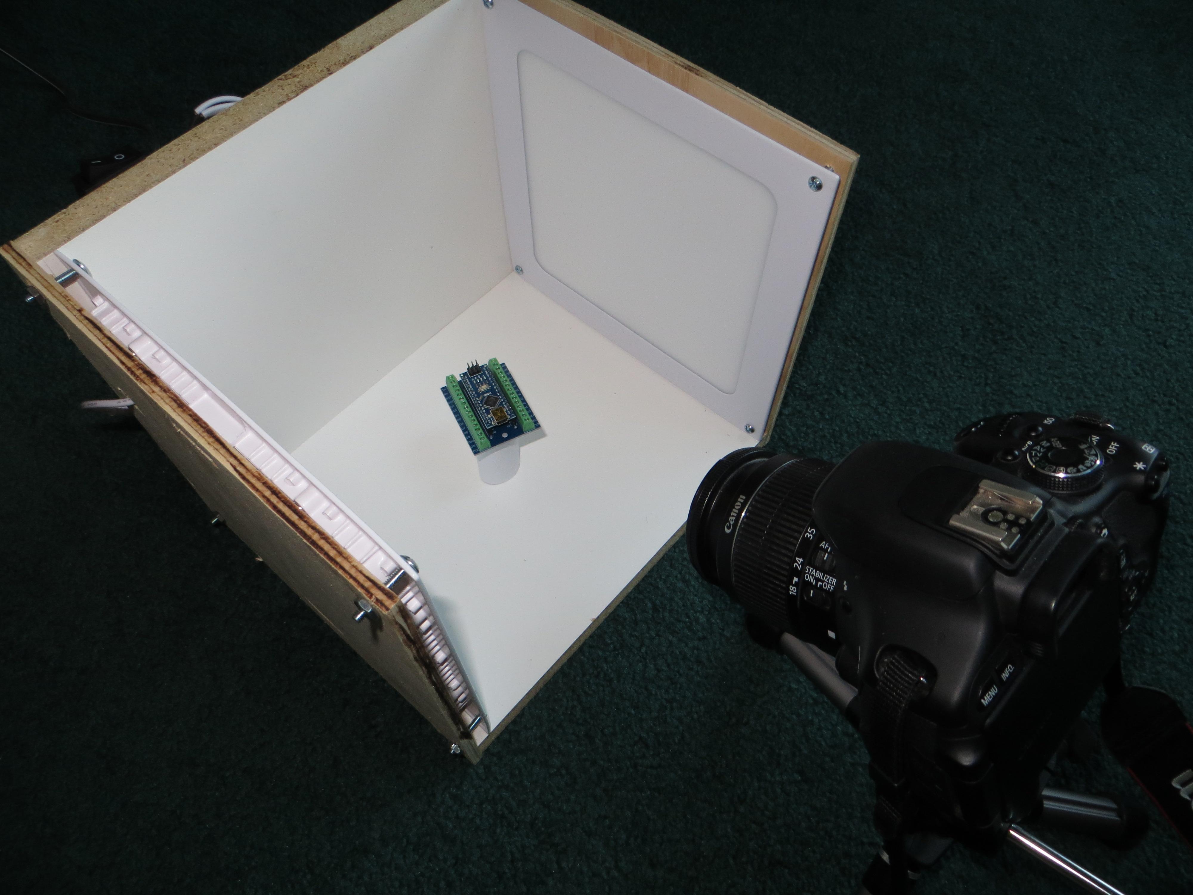
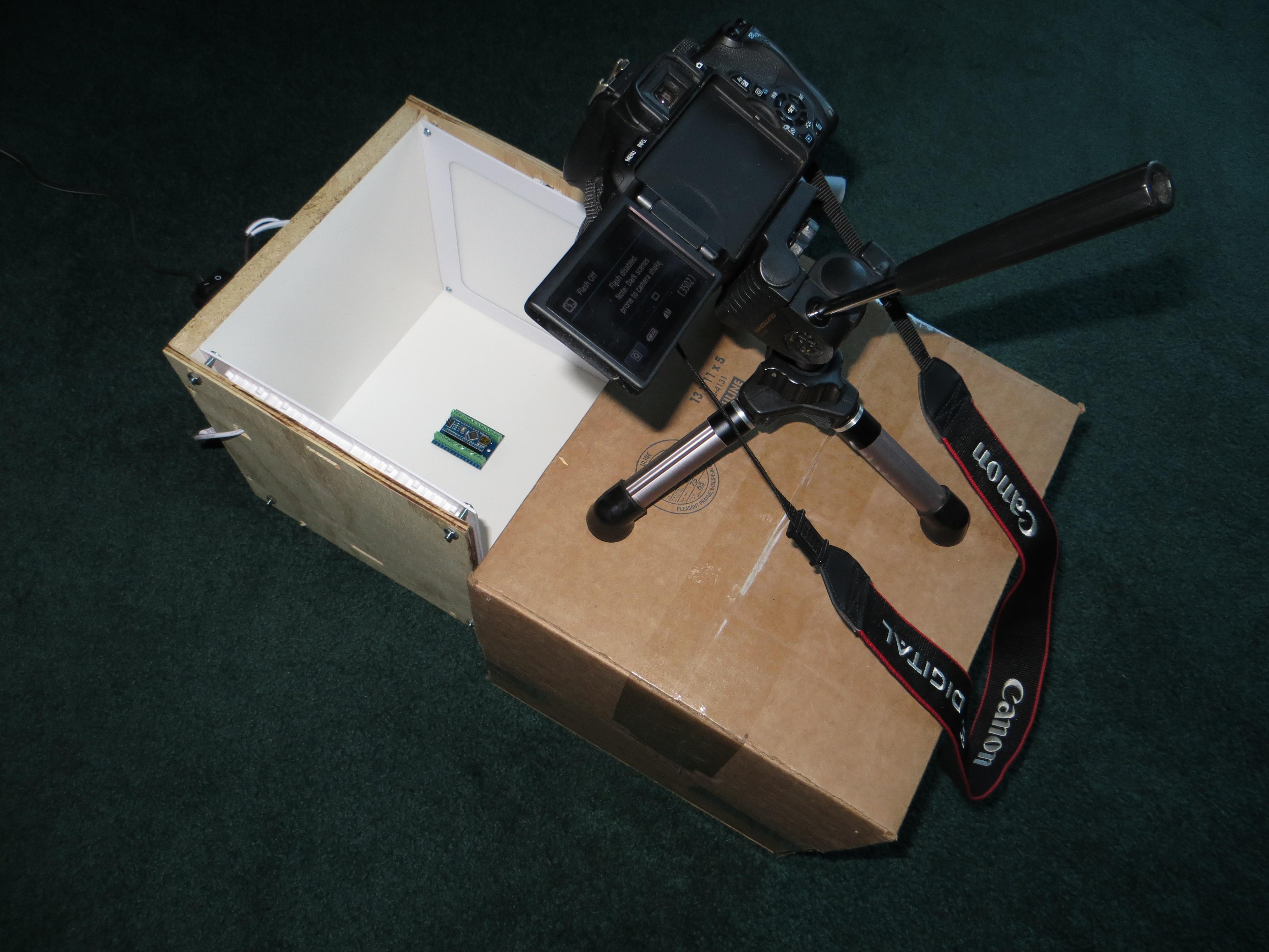
Before explaining how to take pictures, a quick review of photographic theory.
The depth of field (often abbreviated as DOF) is a effect in photography that refers to the range of distances within a scene that appears acceptably sharp (in focus) in an image.
Depth of field is determined by the area in front of and behind the focused subject that remains in focus and it is influenced by aperture, focal length, and distance to the subject.
Aperture:
- The aperture (or f-stop) controls the size of the lens opening.
- A larger aperture (smaller f-number, like f/2.8) results in a shallow depth of field. In this case, only a small portion of the scene is in focus, while the background and foreground are blurred.
- A smaller aperture (larger f-number, like f/16) gives a greater depth of field, making more of the scene sharp.
Focal Length:
- Longer focal lengths (telephoto lenses) tend to have a shallower depth of field.
- Shorter focal lengths (wide-angle lenses) provide a greater depth of field.
Distance to Subject:
- Closer subjects have a shallower depth of field.
- Distant subjects result in a deeper depth of field.
In order to get the whole PCB or project in focus, the best combination is a small aperture (f11 and up), medium focal length (50 mm) and intermediate distance to the subject.
In order to use a small aperture, the shutter speed will be slow and pictures may be subject to blur as a result of camera shake (below shutter speeds of about 1/40 sec, the image will be blurred for a hand held camera). To get round this problem, mount the camera on a tripod and use a remote shutter trigger or the self timer feature.
There are two possible background strategies. There is no specific recommended option, it is personal preference:
- Use the white background of the light box. This has the effect of making the subject “float”. It is also useful for photographs that are destined for webpages; the white background can easily be replaced with a transparent background using image processing software.
- Place a black fabric or paper at the bottom of the box. This has the effect of making the subject “grounded” and provides better contrast. It is more difficult to create a transperent background with this option.
The pictures included here were taken with a DSLR. Most of these cameras have a mode where the aperture can be set manually and the shutter speed is adjusted accordingly. Also, consider setting the focus manually rather than relying on the camera’s auto focus feature.
A typical setup is shown. Make sure there is no extraneous ambient light that can cause spurious shadows or upset the exposure. Experiment with various variables to get the required results.
A smartphone can also be used to take the pictures. There is less control over apetures, shutter sppeds focal length etc. , but the software behind the smartphone camera does a good job of optimizing these variables.
Image Manipulation
Once the pictures are taken, they can be enhanced by processing them through image manipulation software. Most software will provide a set of features that will improve the final result. There are probably four manipulations that can be used
Crop:
Reduce the extra background around the image to focus on the subject
Sharpen:
Improve the sharpness of the image
Color Correction:
The adjustment here allows for three variables to be adjusted – Brightness, Gamma and Contrast. Some software will have a auto feature that will optimize the image with a single button click
White Balance:
If available, this will adjust the image to balance colors between a white and black and will improve the color saturation of the image
The photos in this project were processed through KolourPaint (available on Linux systems)
Results
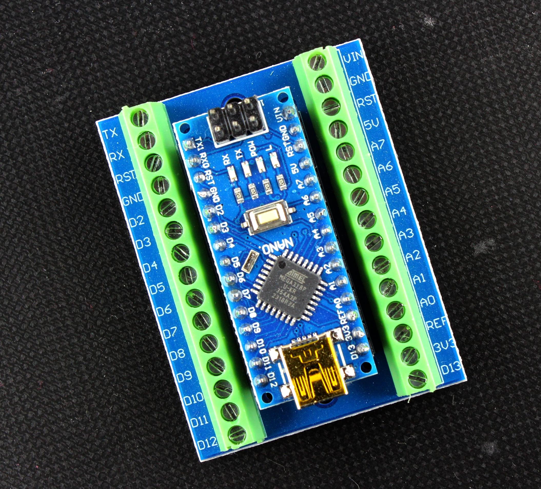
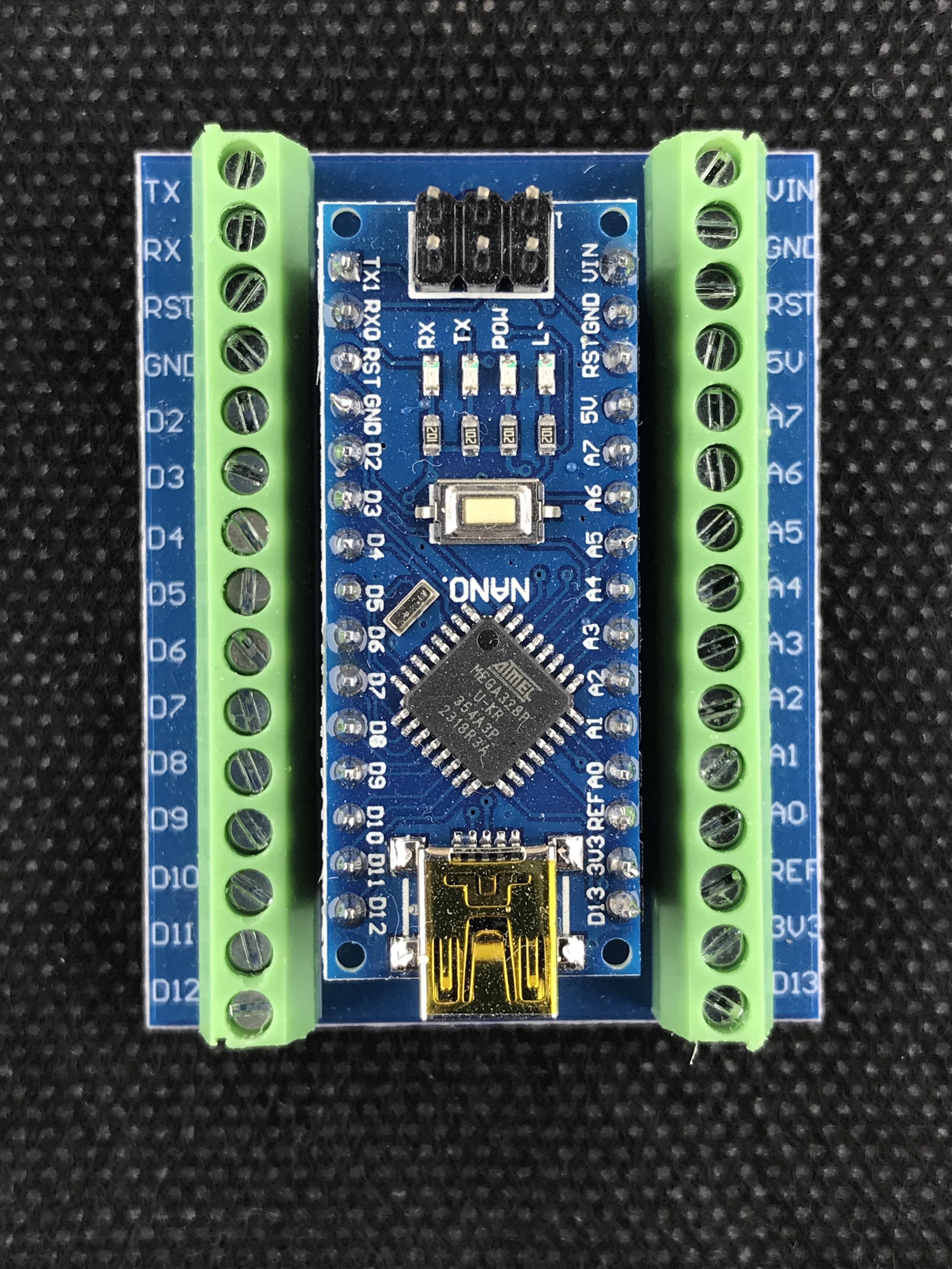
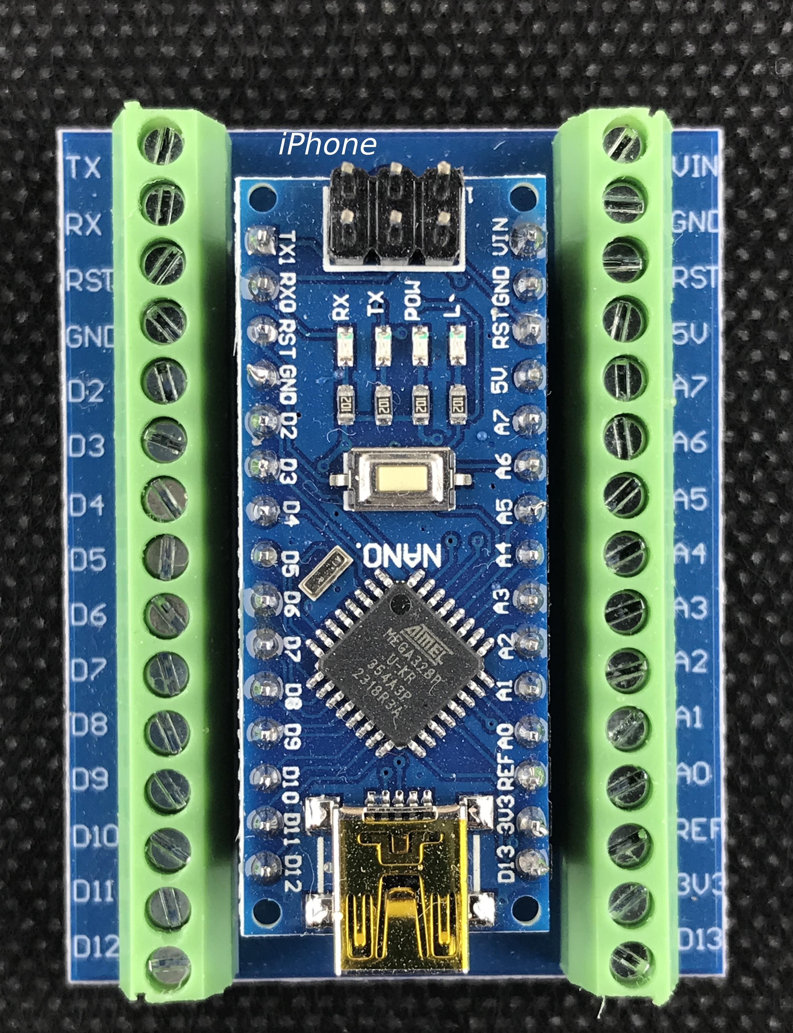
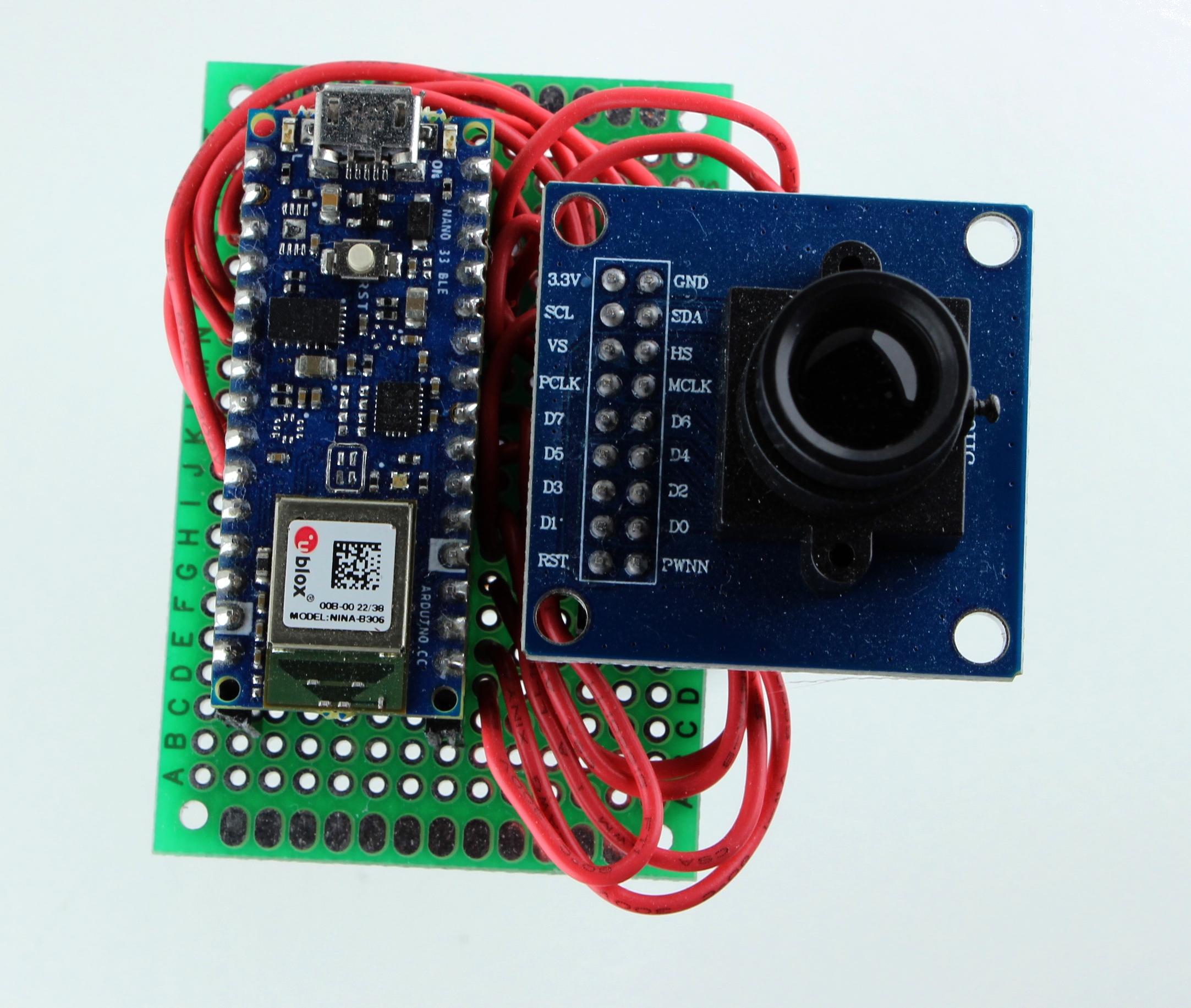
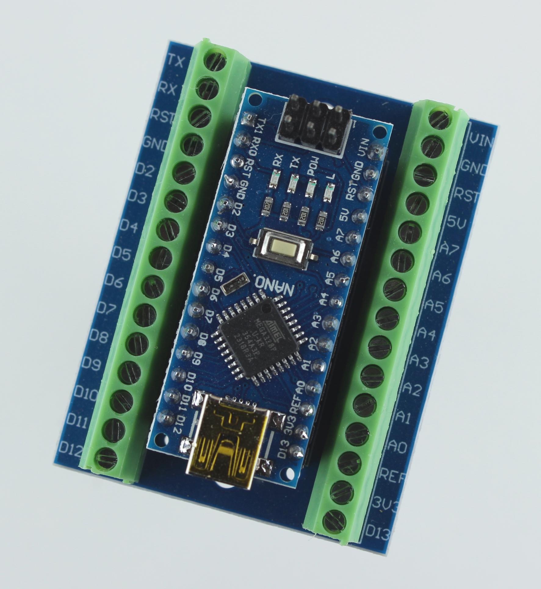
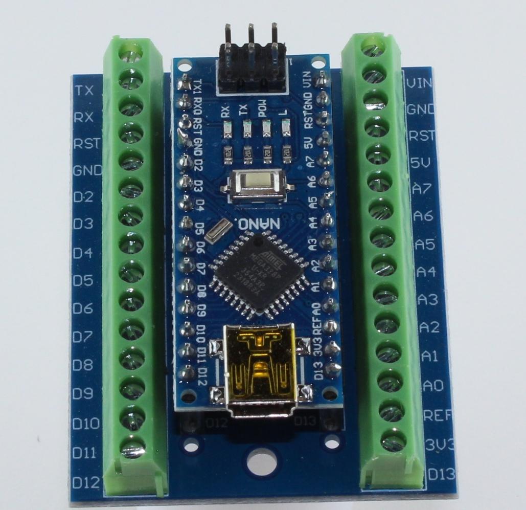
Here are some of the pictures taken using my light box and DSLR camera.