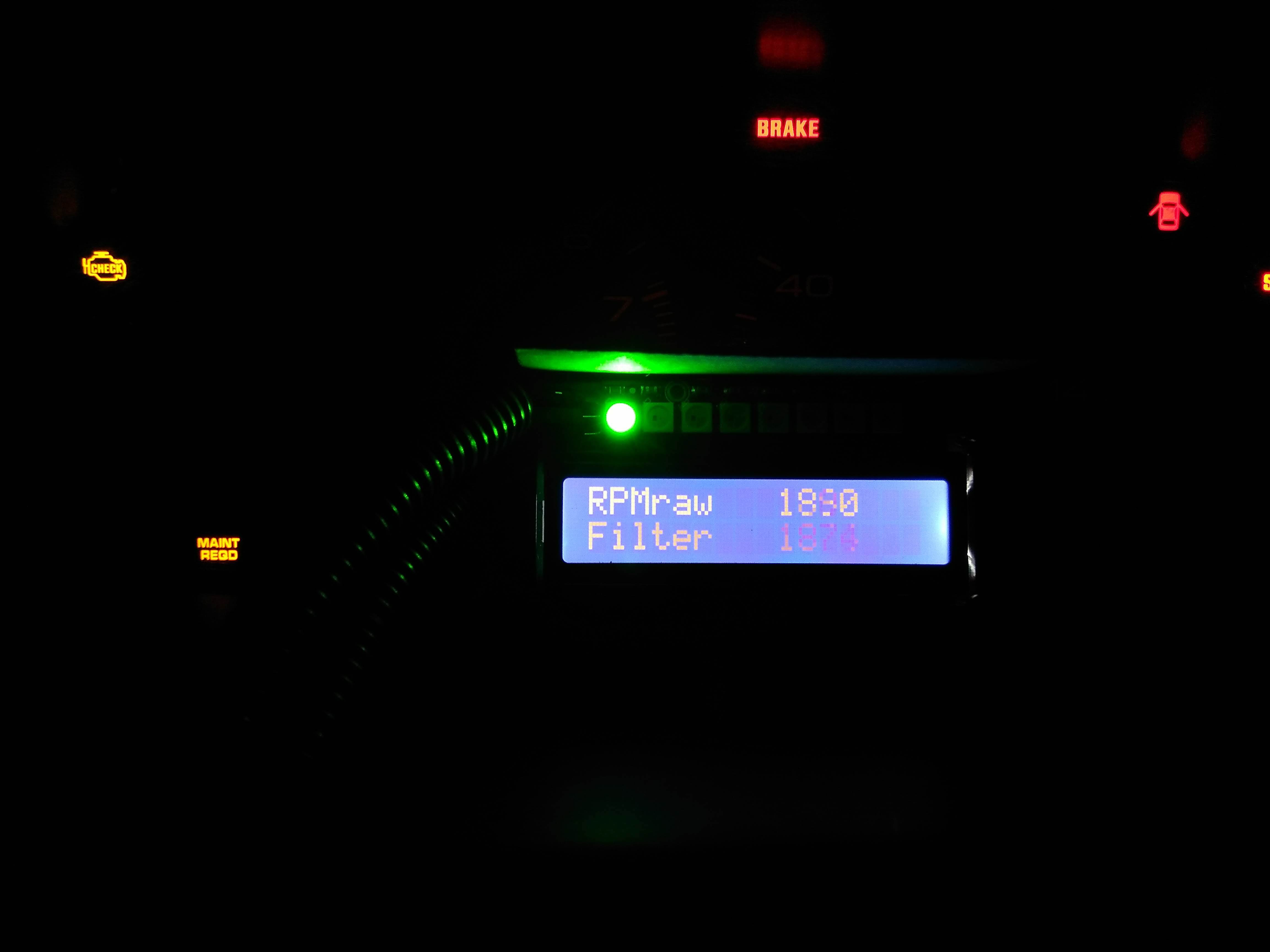
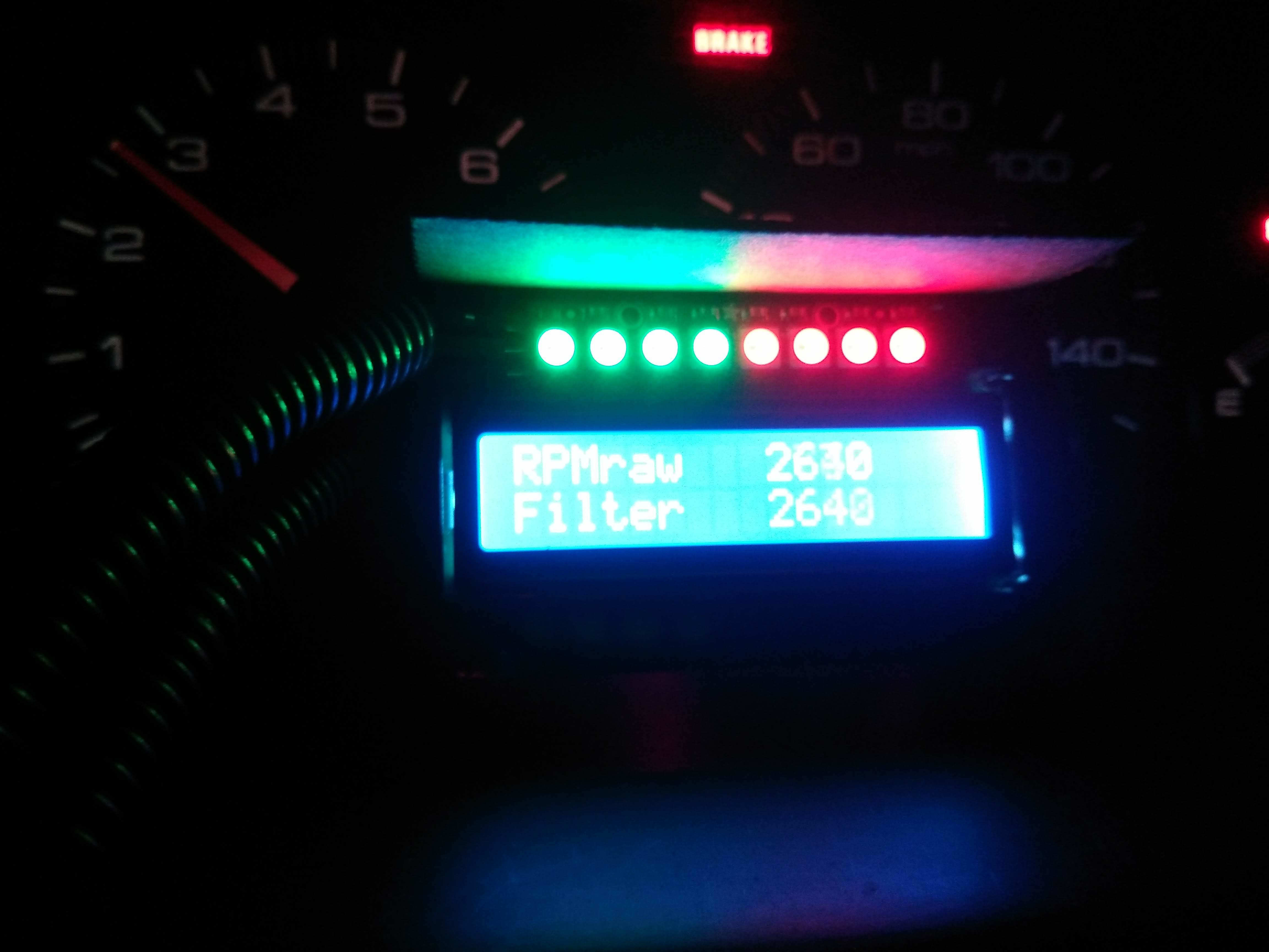
Use Arduino to Display Engine RPM
by TinkeringEngineer in Circuits > Arduino
31789 Views, 71 Favorites, 0 Comments
Use Arduino to Display Engine RPM
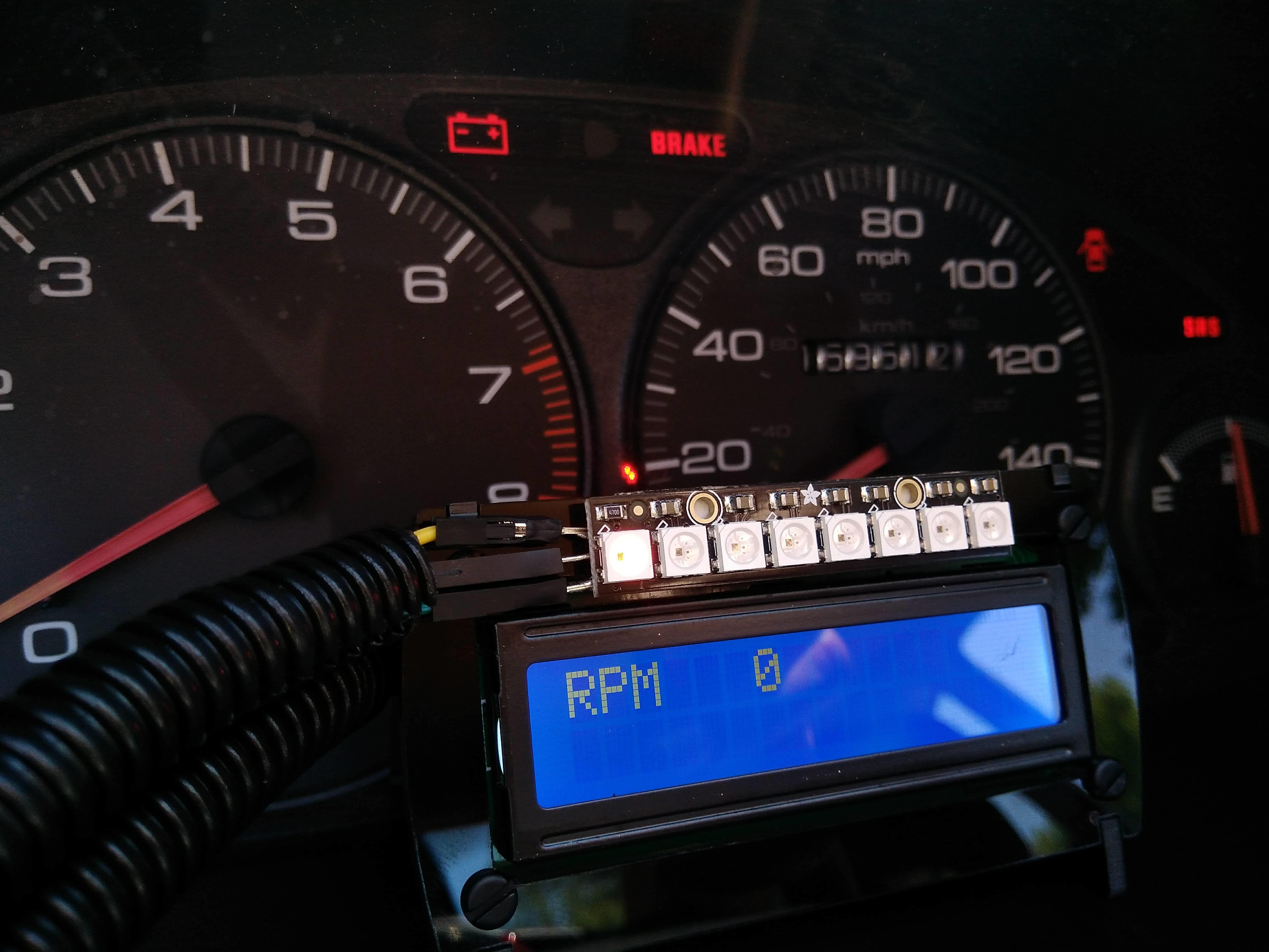
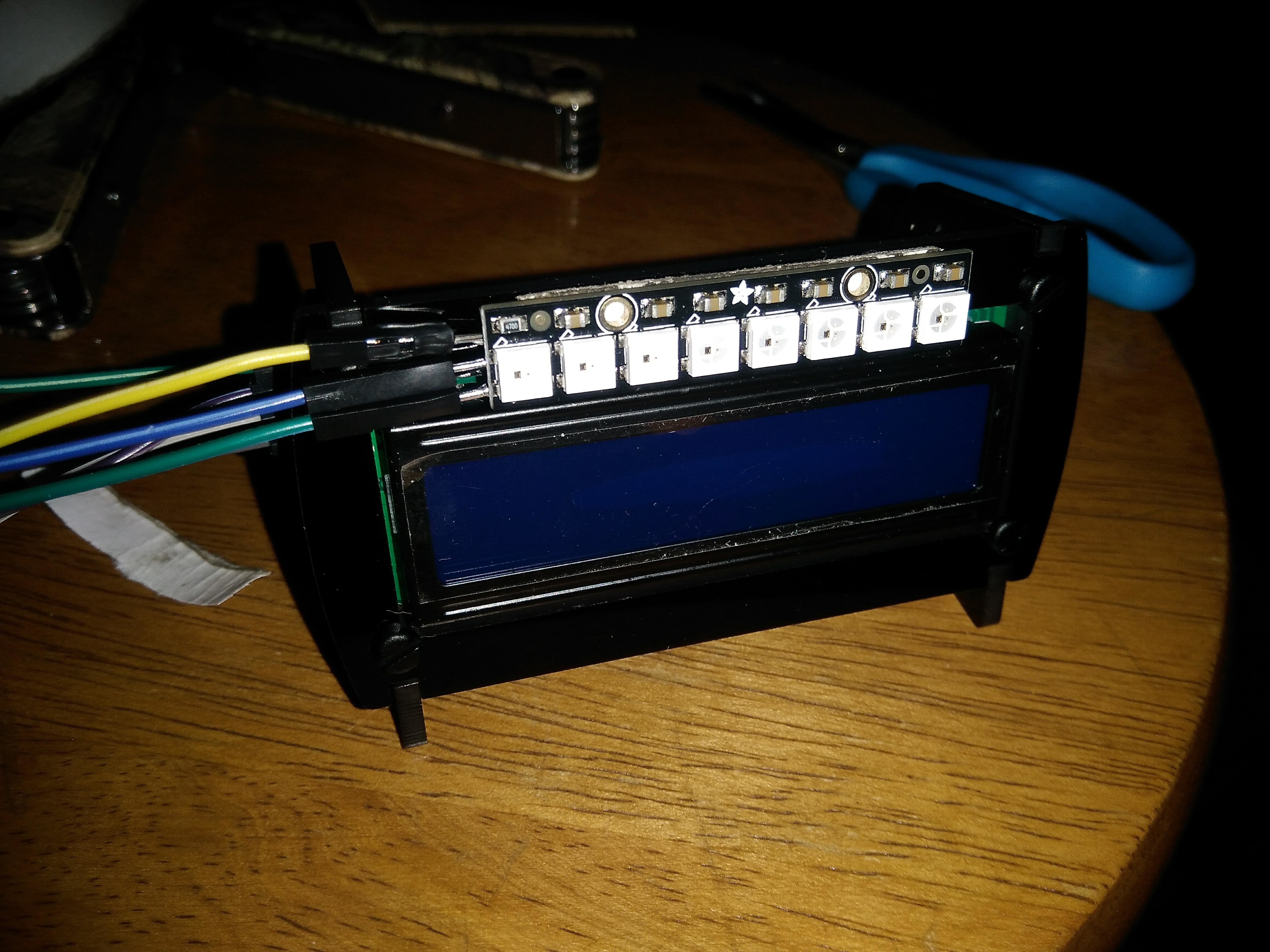
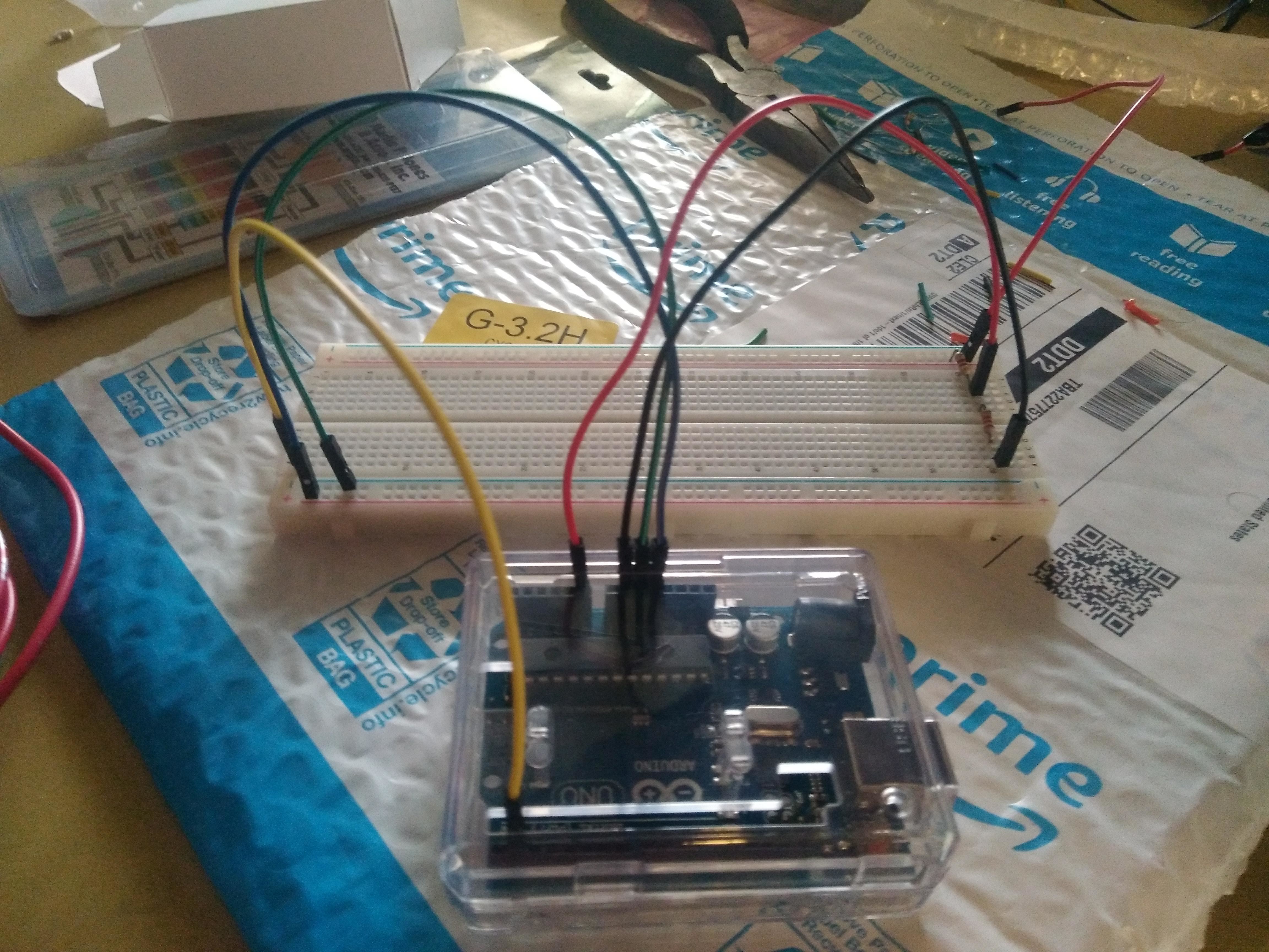
This guide will outline how I used an Arduino UNO R3, a 16x2 LCD display with I2C, and an LED strip to be used as a engine speed gauge and shift light in my Acura Integra track car. It is written in terms of someone with some experience or exposure to Arduino software or coding in general, the mathematical software MATLAB, and creating or modifying electric circuits. In the future this may be revised to be easier to understand for someone with little to no experience with these topics.
Choose a Sigal Wire
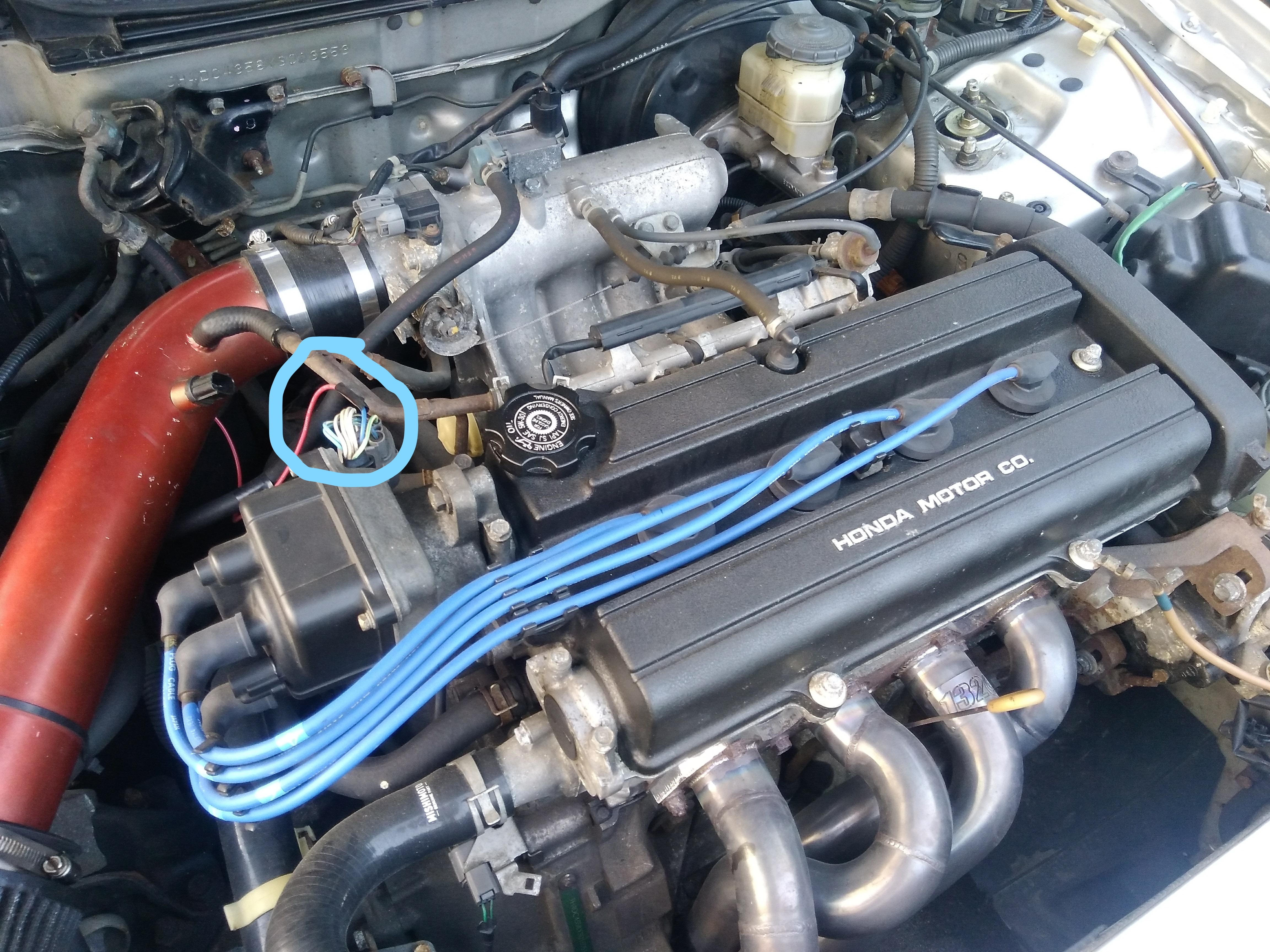
You'll need to get a signal that correlates to engine speed. It is possible to add a system that measures engine speed but it is far more practical to tap into an existing wire that carries engine speed information. A single car may have multiple sources for this, and it may vary wildly even year-to-year on a single vehicle model. For the sake of this tutorial I will be using the example of my car, a track modified 2000 Acura Integra LS. I found on my engine (B18B1 with OBD2) there is an unused voltage out that is 12V high and drops to 0V upon completing a full revolution.
Things that will help identify a potential engine speed signal:
- Wiring diagram for your vehicle
- Searching forums for your vehicle involving engine/ECU signals
- A friendly mechanic or car enthusiast
Extend Wire to Arduino Board
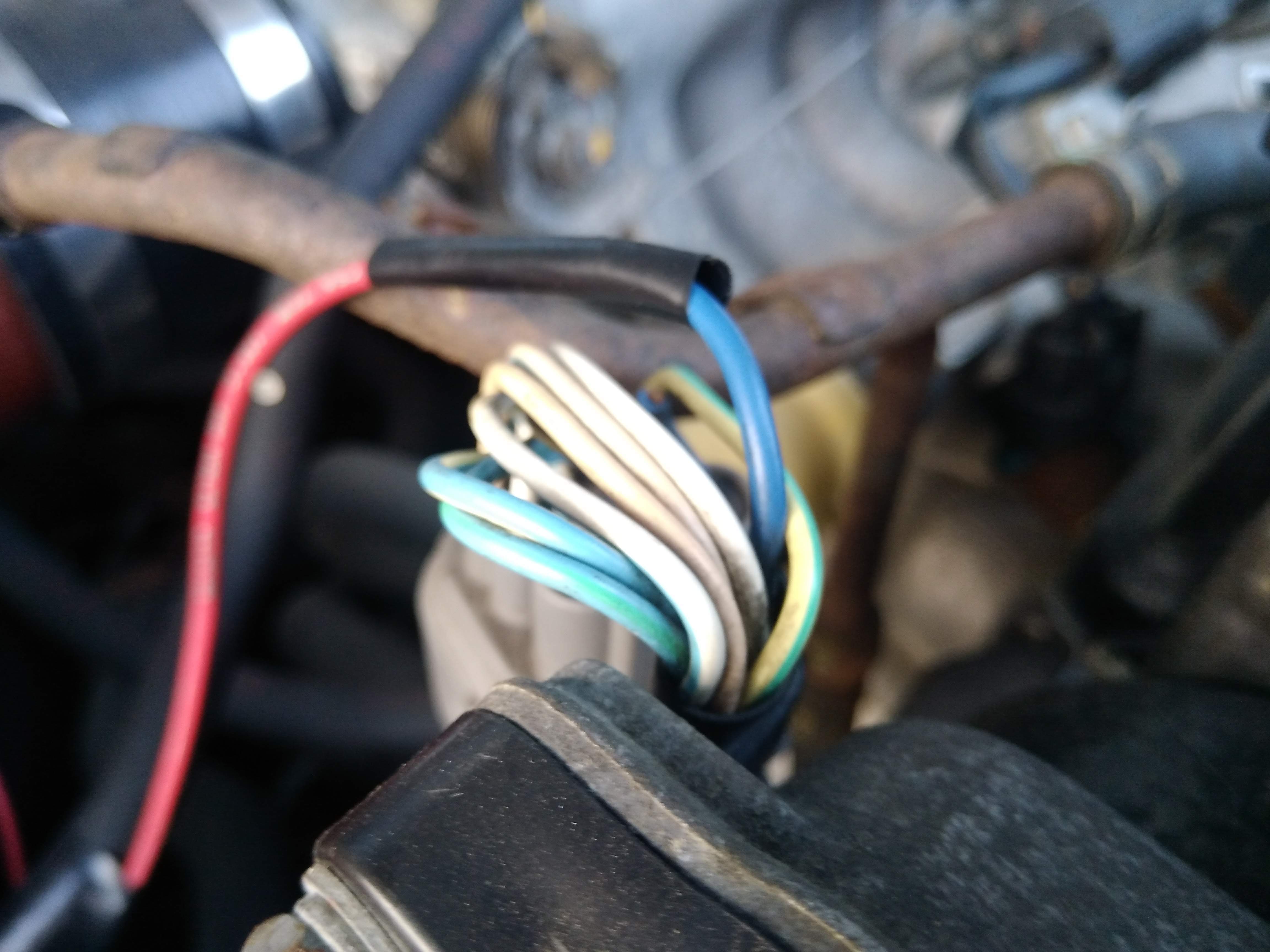
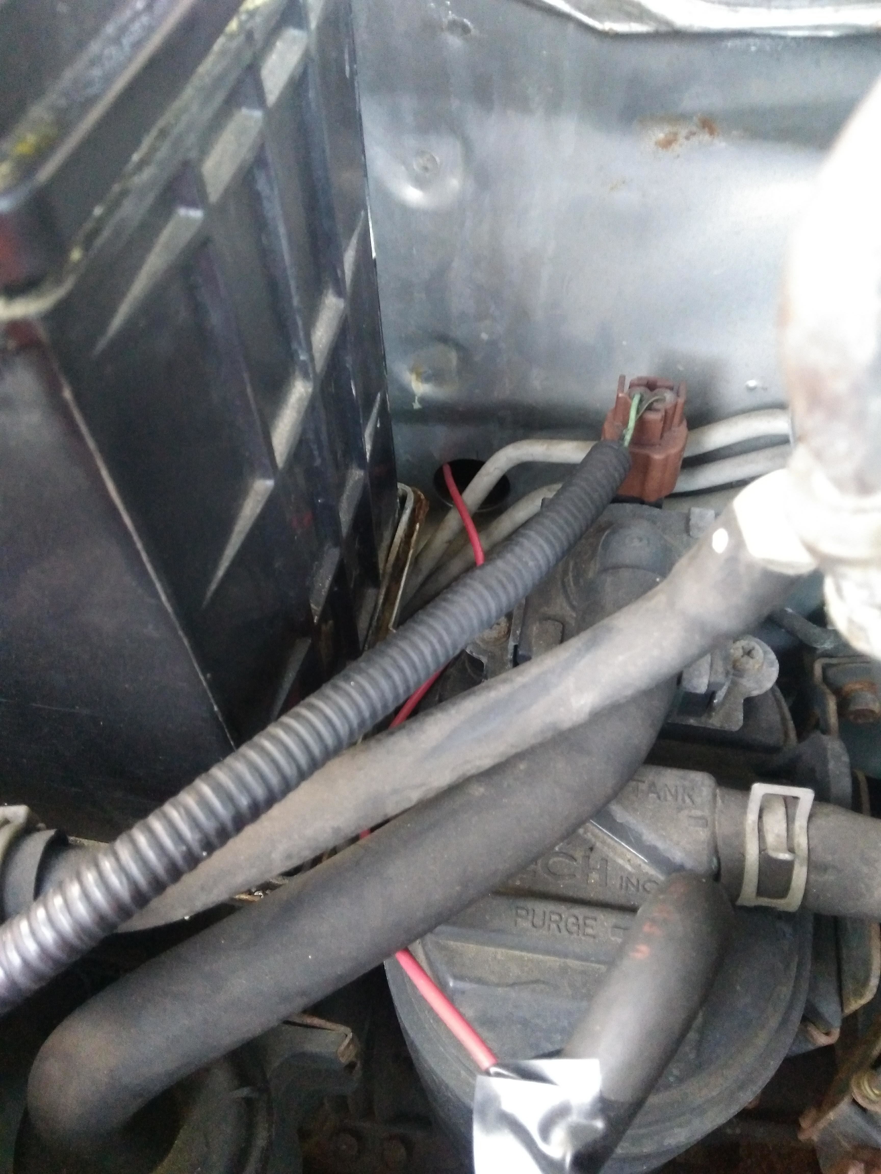
Once you have chosen a suitable signal, you'll need to extend it to wherever you are placing your Arduino board. I decided to place mine inside the vehicle where the radio used to be, so I routed the new wire from the engine, through a rubber grommet in the fire wall, and right to the radio area. Since there are already an abundant amount of how-to guides on stripping, soldering, and protecting wiring I will not explain this process.
Signal Analysis
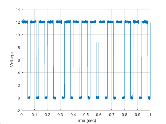
This is where can things get complicated. Having a general understanding of signal analysis and controls will help you a long way, but is doable with little knowledge.
The signal wire chosen most likely will not be spitting out the exact value of the engine speed. It will need to be shaped and modified into giving the exact number of engine RPM you want. Due to the fact every different car and signal wire chose may be different, from this point onward I will explain how I used the position signal from the distributor on my Integra.
My signal is normally 12V and drops to 0V when completing one full rotation. If you know the time to complete one full rotation, or one full cycle, this can easily be translated into revolutions/min using some basic concepts.
1 / (seconds per cycle) = cycles per second, or Hz
Revolutions per minute = Hz * 60
Code Your Signal Analysis

This method requires getting the time it takes for the input signal to complete one full cycle. Luckily the Arduino IDE software has a command that does exactly that, PulseIn.
This command will wait for a signal to cross a threshold, start counting, and stop counting when the threshold is crossed again. There are some details that should be noted when using the command, so I will include a link to information of PulseIn here: https://www.arduino.cc/en/Reference.PulseIn
PulseIn will return a value in microseconds, and to keep the math simple this should be immediately converted into normal seconds. Following the math on the previous step, this duration of time can be equated directly into RPM.
Note: after trial and error I discovered the distributor completes two rotations for every single rotation of the engine crankshaft, so I simply divided my answer by 2 to account for that.
Identify a Filter
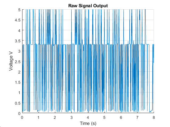
If you're lucky your signal will have no ‘noise’ (fluctuations) and your engine speed will be exact. In my case, there was a lot of noise coming from the distributor that often gave voltages far from what is expected. This turns into very false readings of the actual engine speed. This noise will need to be filtered out.
After some signal analysis, almost all of the noise came at frequencies (Hz) far higher than what the engine itself was outputting (which is true for most real dynamic systems). This means a low pass filter is an ideal candidate to take care of this.
A low pass filter allows low frequencies (desired) to pass through and attenuates the high frequencies (undesired).
Filtering: Part 1
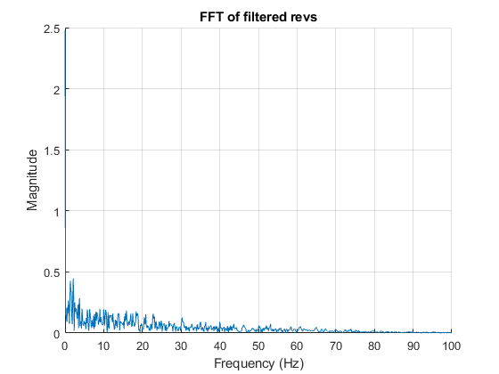
Designing the filter can be done by hand, however utilizing MATLAB will speed this up significantly if you have access to the software.
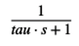
A low pass filter can be equated to a transfer function (or fraction) in the Laplace domain (frequency domain). The input frequency will be multiplied by this fraction and the output is a filtered signal that only has the information you want to use.
The only variable in the function is tau. Tau is equal to 1 / Omega, where Omega is the cutoff frequency you want (must be in radians per second). The cutoff frequency is the limit where frequencies higher than it will be removed and frequencies lower than it will be kept.
I set the cutoff frequency equal to an RPM my engine will never reach (990 RPM or 165 Hz).
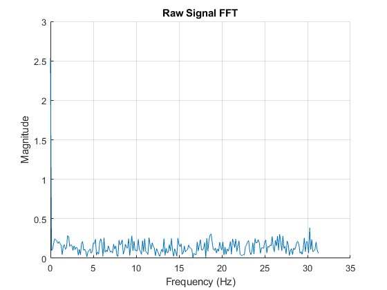
The FFT graphs show roughly what frequencies my raw signal were carrying and the frequencies that came out of the filter.
Filtering: Part 2

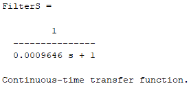
Here MATLAB was utilized again for the sake of time. The cutoff frequency is defined, and from that the resulting transfer function is displayed. Keep in mind this fraction only applies to the Laplace domain and cannot be directly used on a time-based micro controller like Arduino UNO R3.
Filtering: Part 3

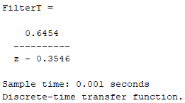
MATLAB has a command that will convert a continuous function (frequency domain) into a discrete function (time domain). The output of this command will provide an equation that can be easily incorporated into Arduino IDE code.
Filtering: Part 4


In the Arduino sketch, include the variables u and y before the setup. The float command simply defines how the variable will store data (things like maximum value, decimals, etc...) and a link to more information on this will be provided here: https://www.arduino.cc/reference/en/language/varia...
In the loop where the conversion from the raw signal into engine speed is taking place, include the u variable and the y multiple equation. There are multiple ways of employing this, but the variable u should be set equal to the raw input signal being measured, and the variable y will be the filtered value.
Display Your Filtered Engine Speed!
