Upgrade Your CNC
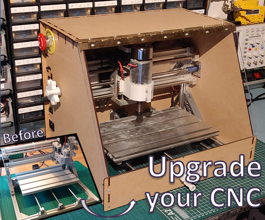
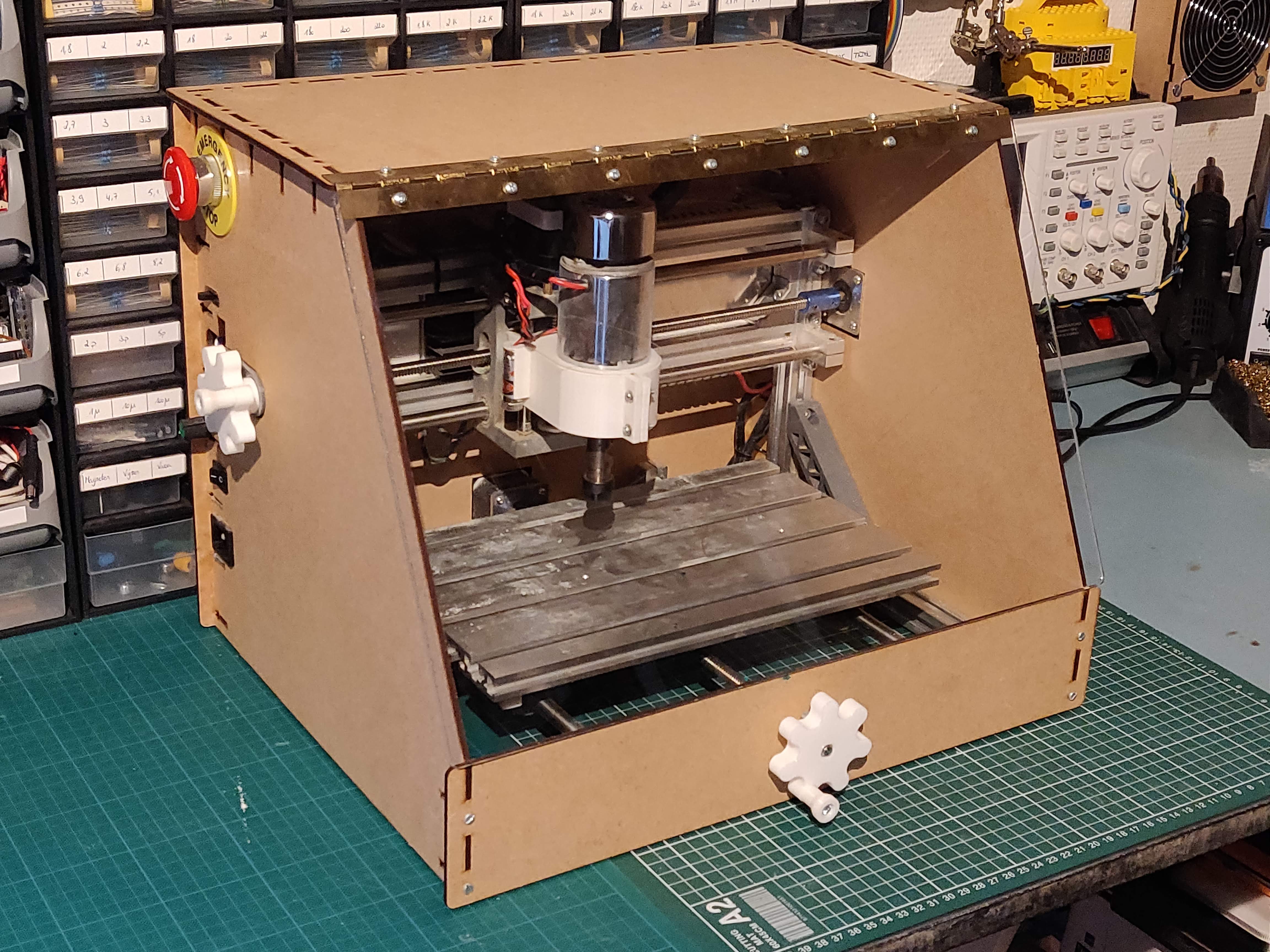
CNC machines are more accessible than ever, with the large range of cheap CNC machine kits from China. The most common type are the 1610, 2416 or 3018 types, referring to the dimension of their machine bed. While they are great machines for their price, their performance is not that terrific. With a few upgrades however, the quality and safety can greatly be improved to turn it into a very potent CNC machine!
In this instructable, I will walk you through the upgrades I made to my machine, including:
- Adding safety features
- Upgrading the spindle to cut aluminium
- Adding bluetooth control
- Adding an enclosure
- Adding manual control
We will start this guide with an assembled CNC kit. There is enough documentation already for the assembly of these kits, so I will focus on the upgrades only.
Most upgrades will be 3D printed. The necessary files are included in each step, as well as a wiring diagram. Besides a 3D printer, we'll also need a soldering iron and some basic tools.
Let's get started!
Cable Management
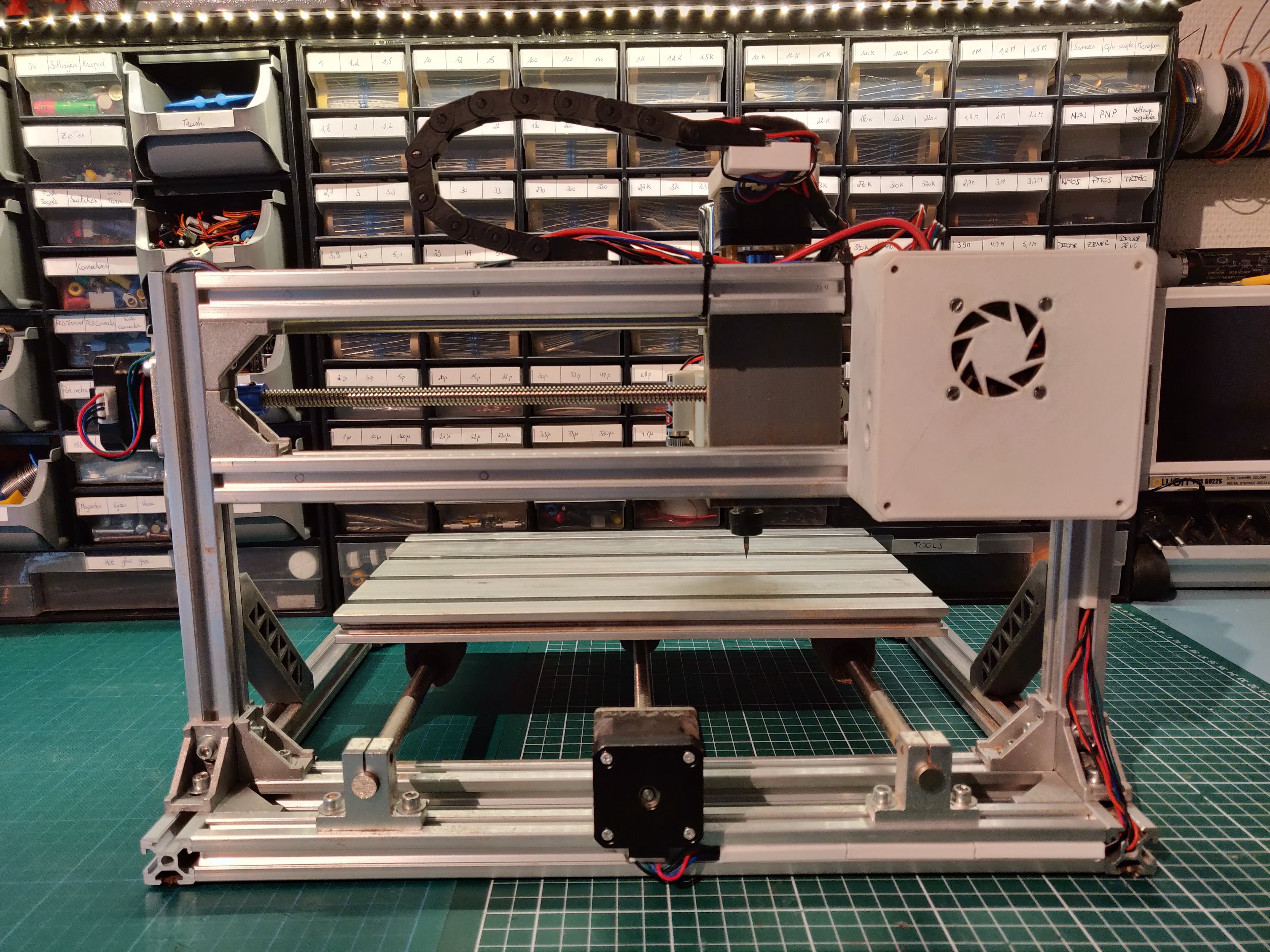
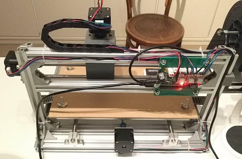
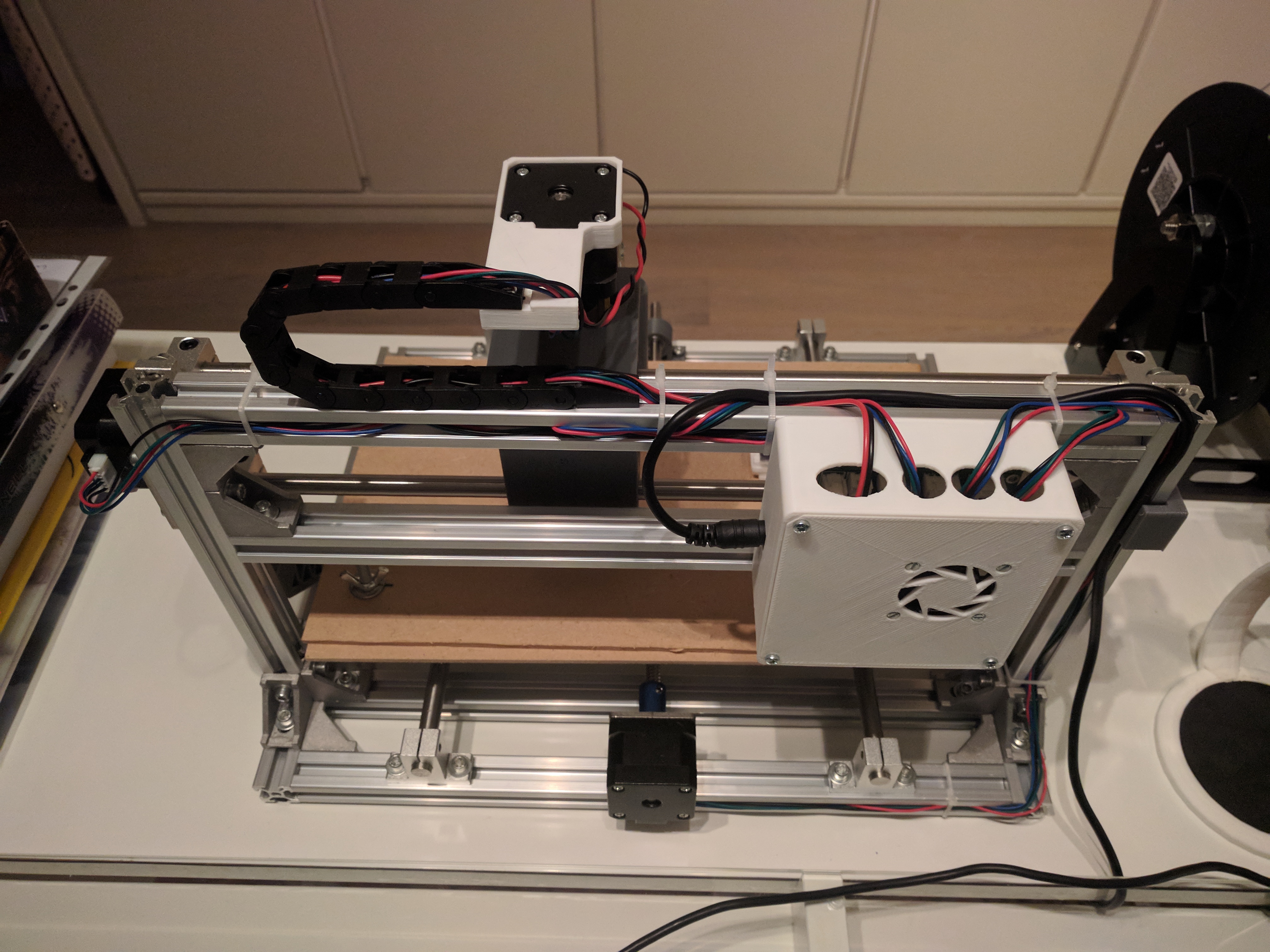
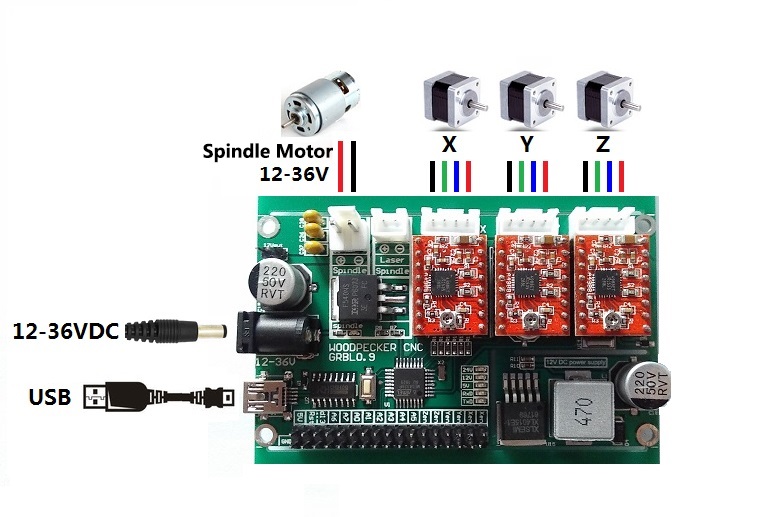
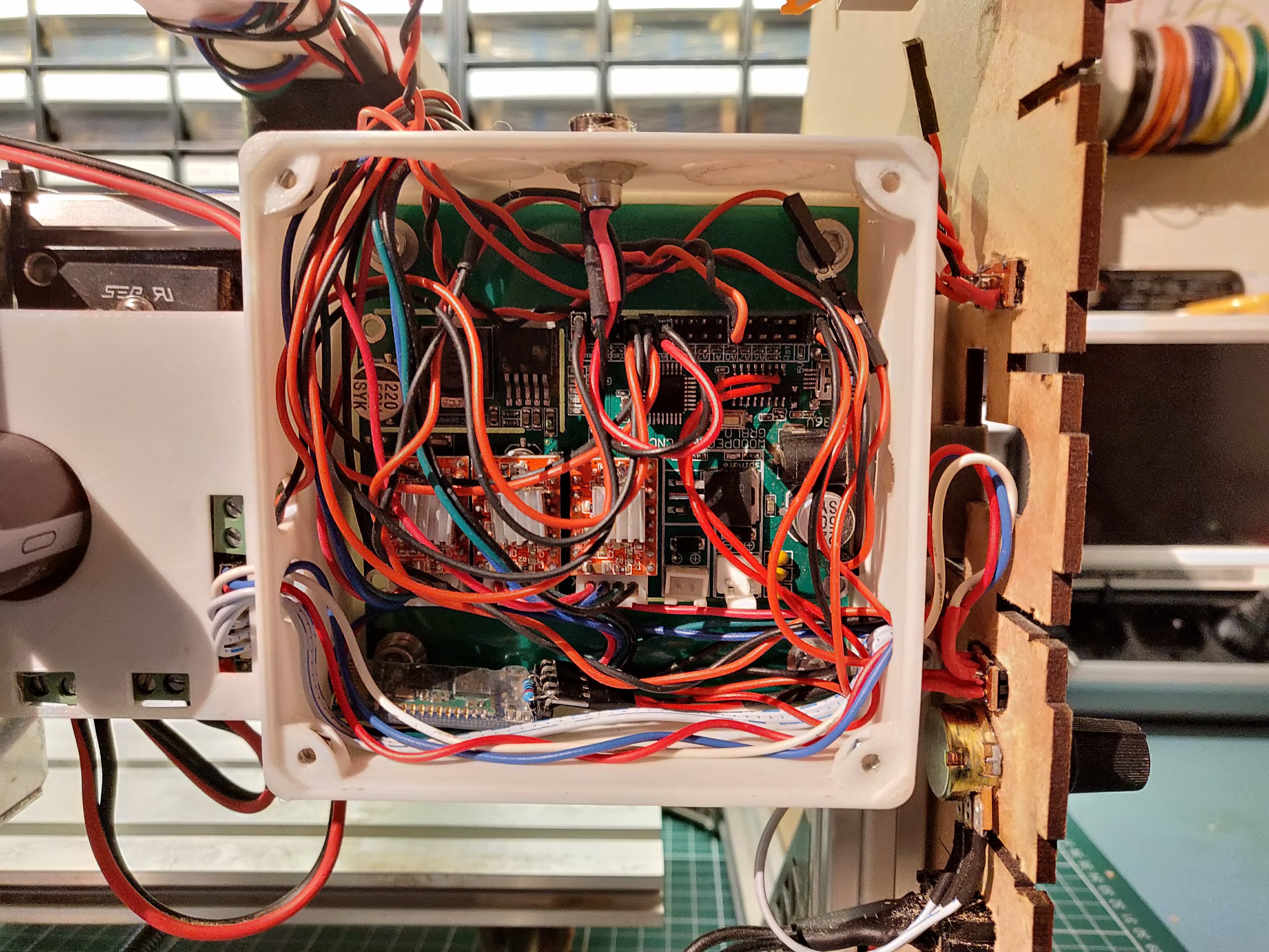
As a first step, we will put the electronics in an enclosure and nicely route the cables to the main board. This protects the PCB from dust, and shorts in the case of milling aluminium.
Furthermore, we will add a drag chain for the wires.
Parts in this step
- Drag chain 15 mm x 25 cm
- 40 mm fan 12V
- Zip ties
Electronics box
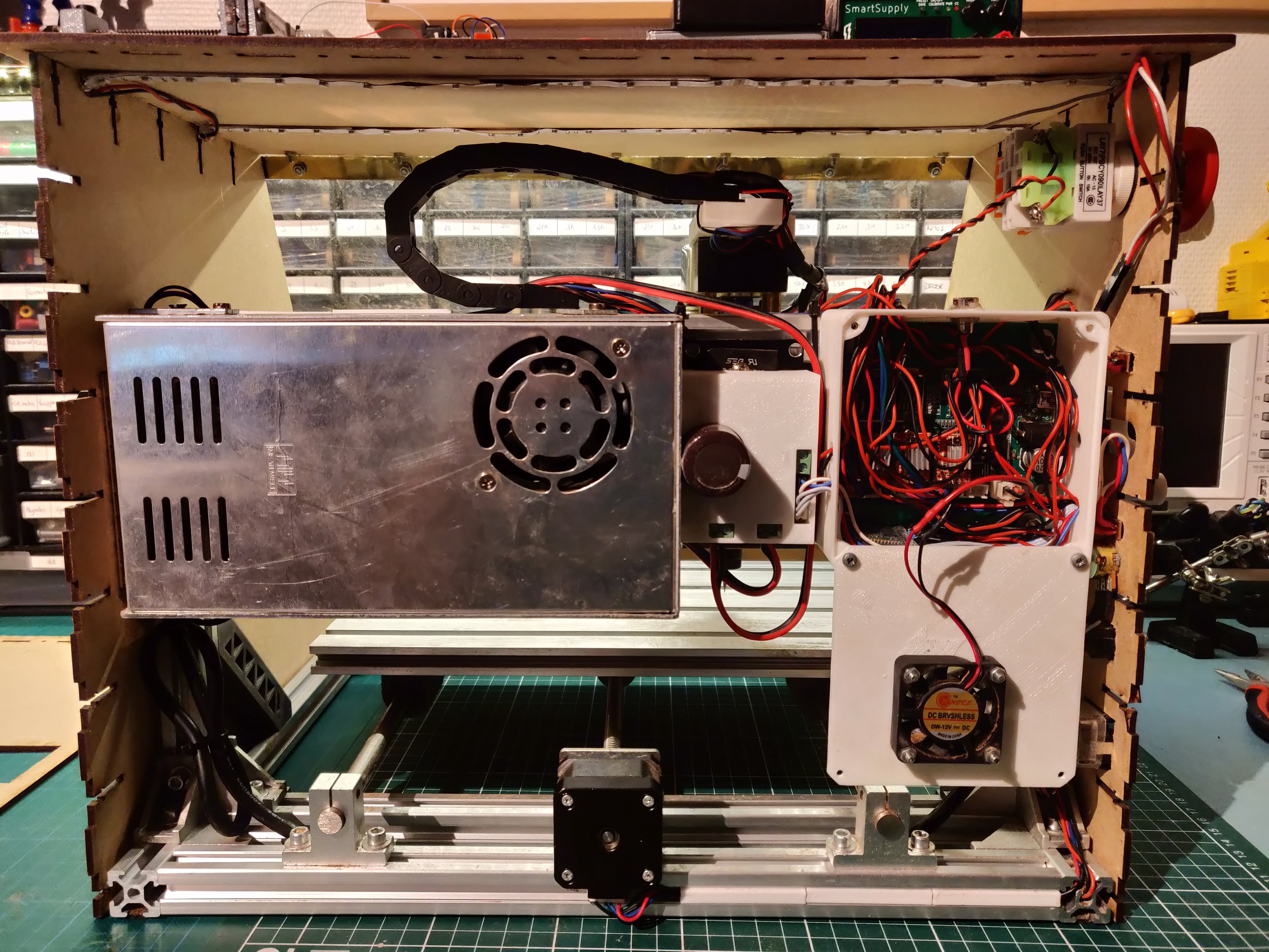
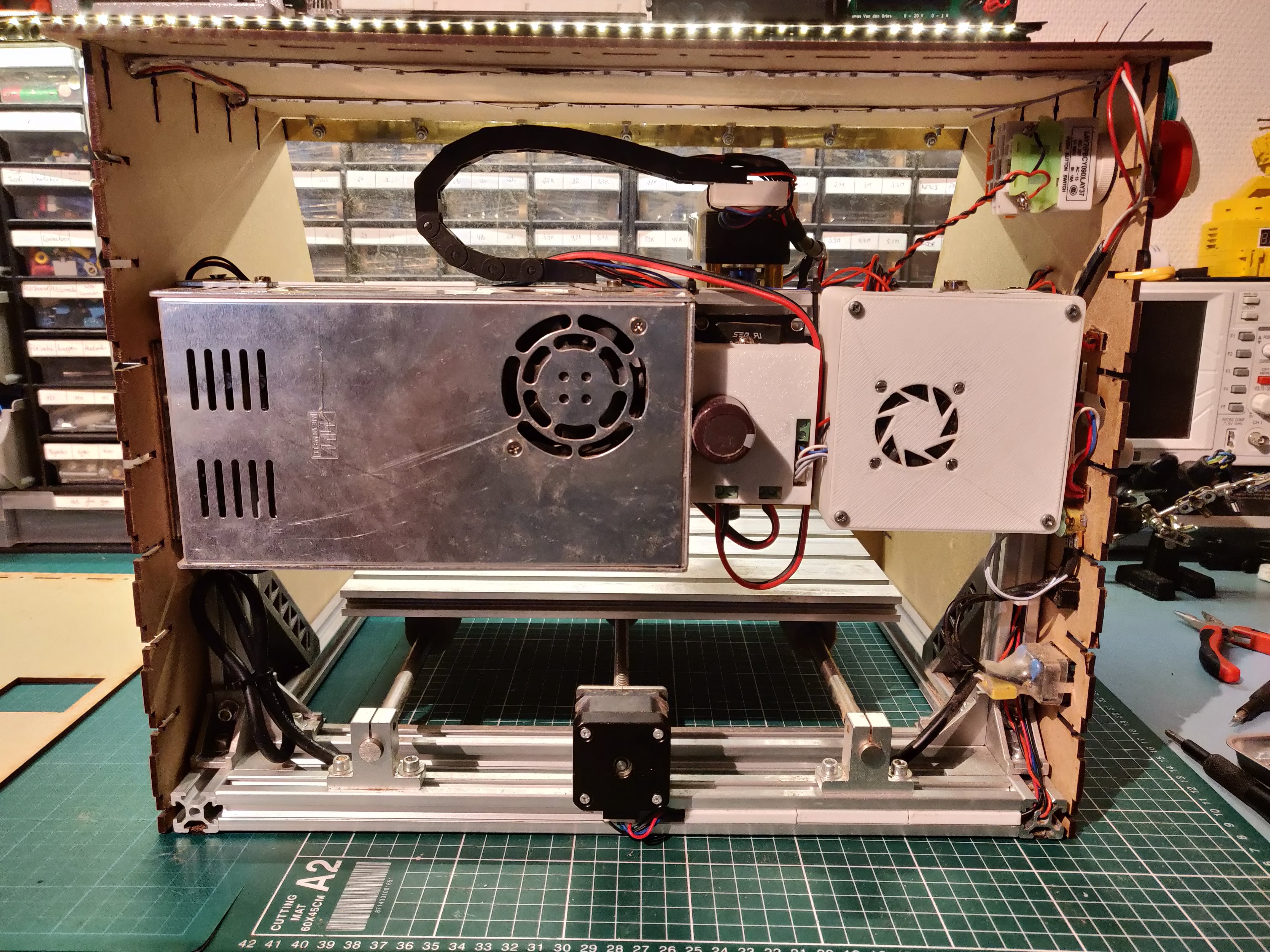
Start by printing Electronics_box.stl and Electronics_lid.stl and install it on the CNC. Add a fan to the inside and connect it to the 12V powersupply. Neatly route all stepper motor cables to the box and secure with zip ties.
Cableguide.stl is a part which fits in the channel of the extruded aluminium and allows for even nicer cable management.
Drag chain
Print DragchainCoupler.stl and place it on the Z stepper motor. The drag chain can be bolted to this part and also secured to the aluminium rails. When routing the wires through the dragchain, it is a good time to add 2 extra pairs of red and black wires for the next steps.
Add Homing Switches and Soft Limits
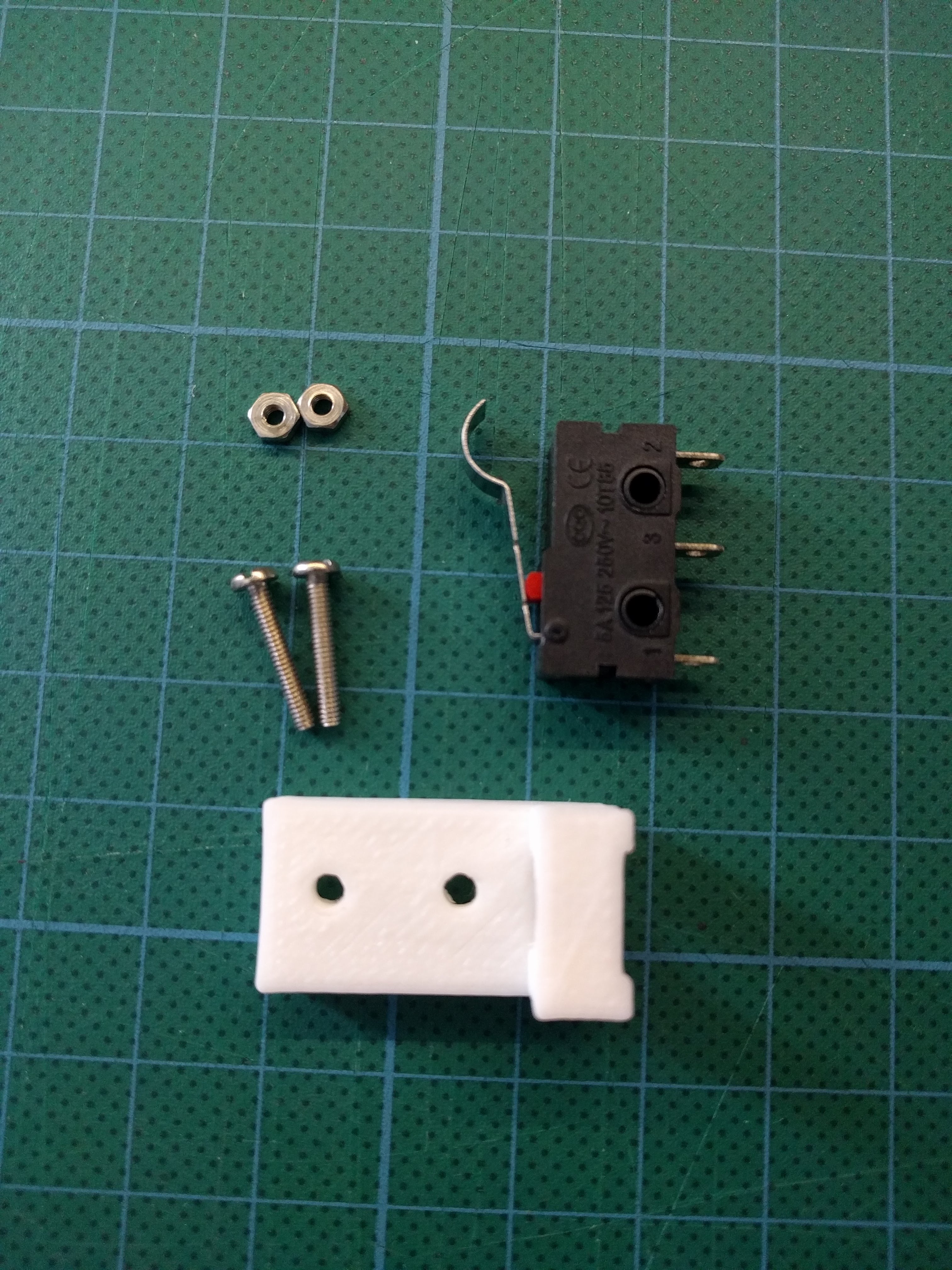
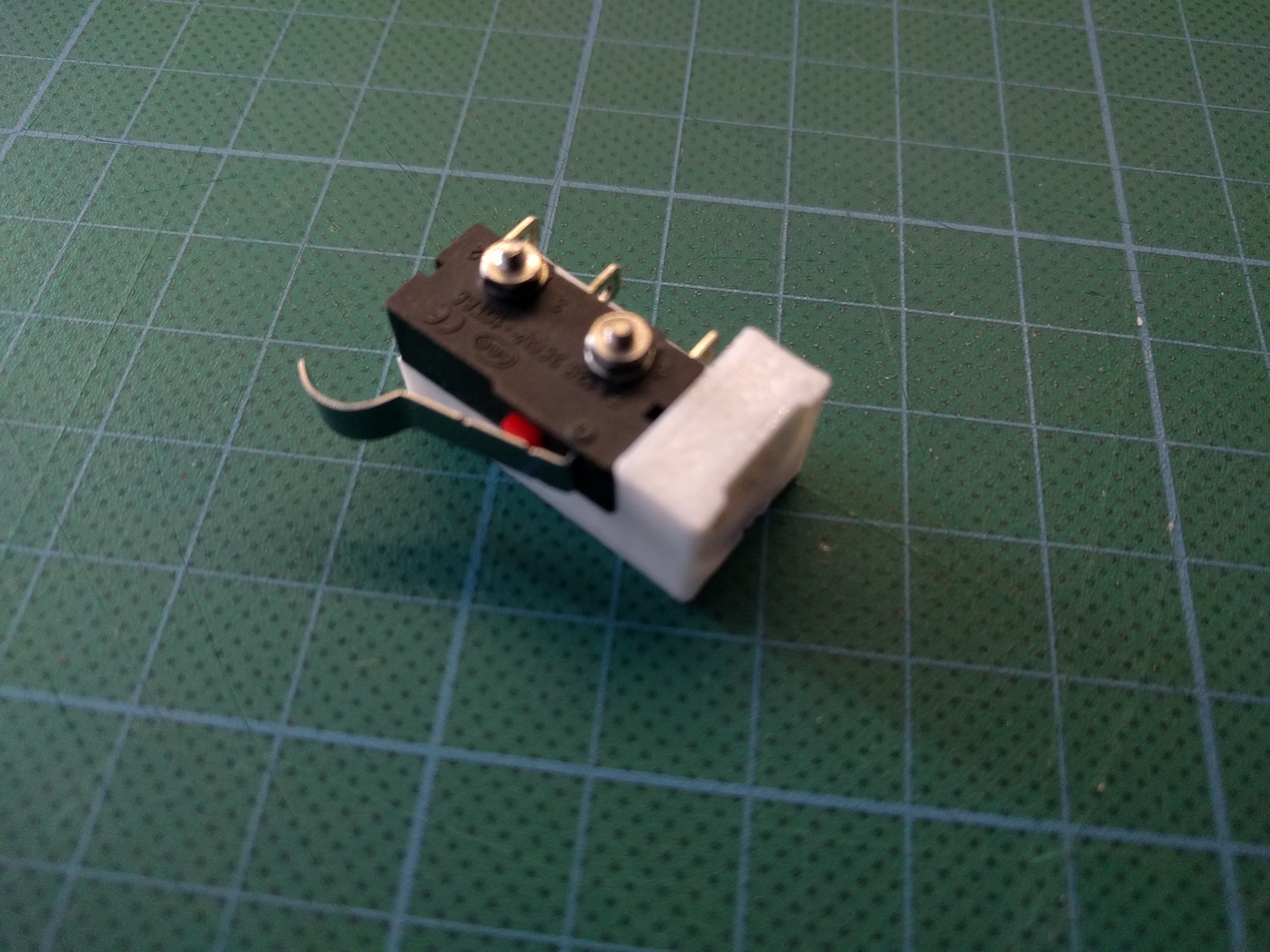
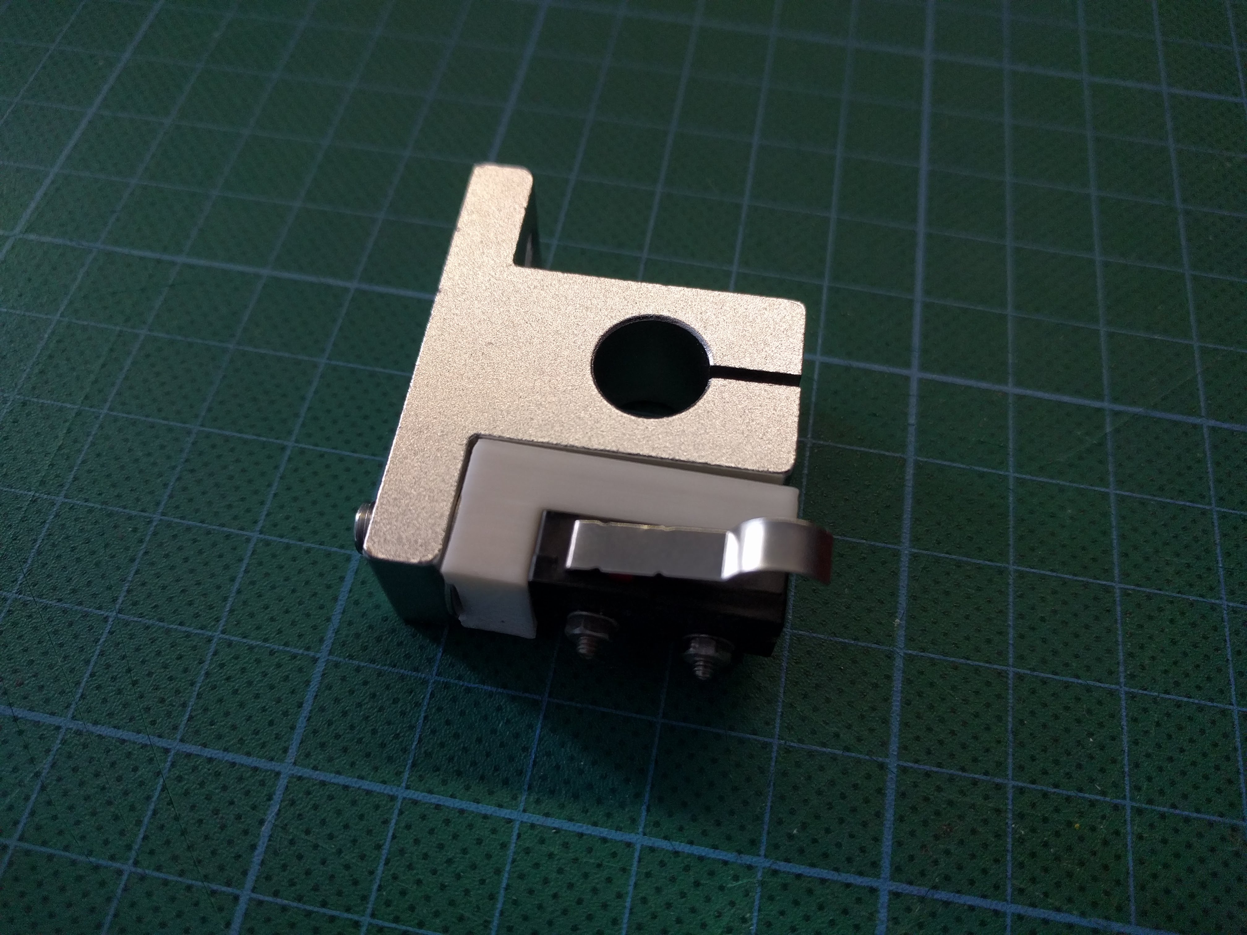
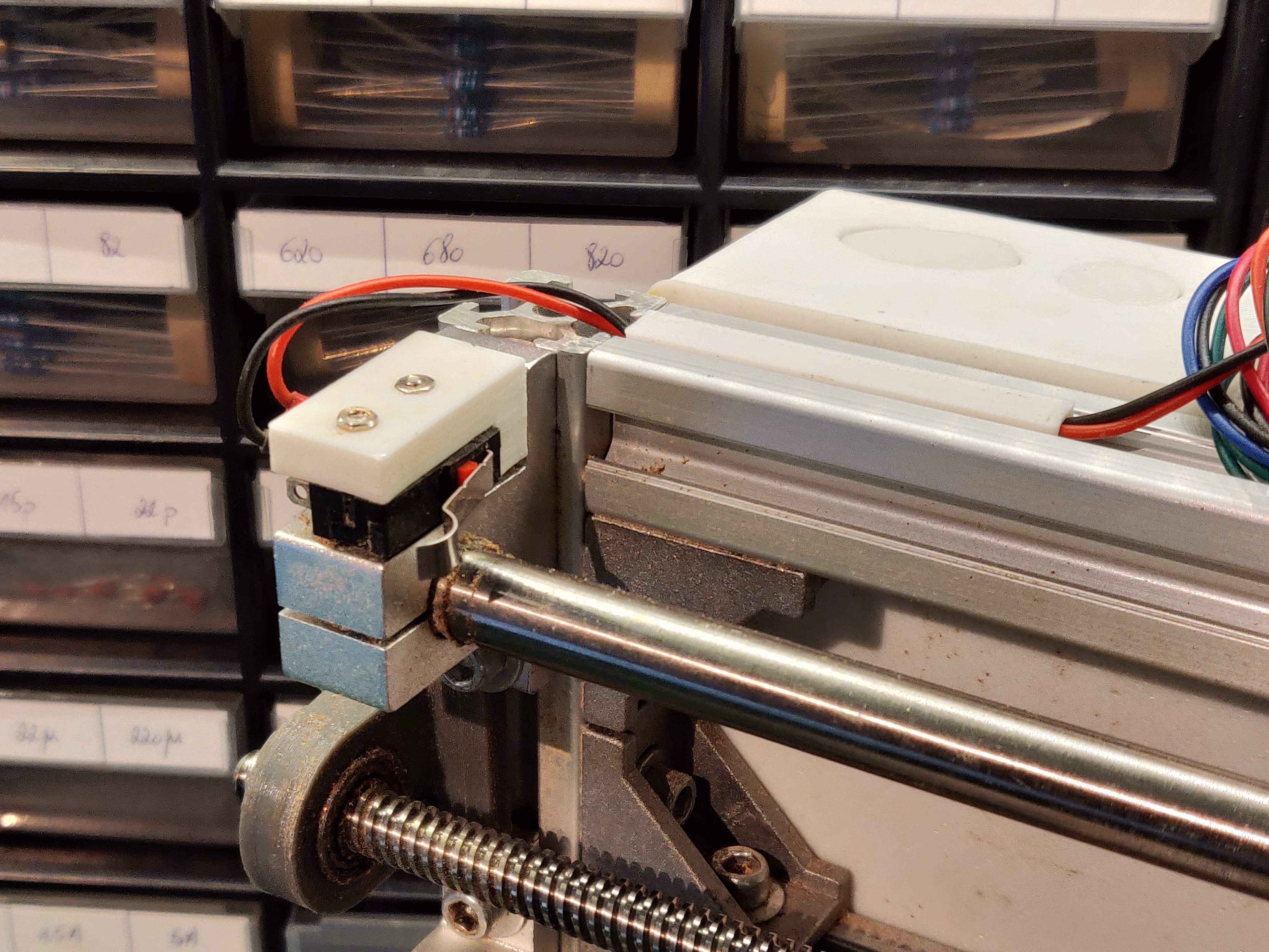
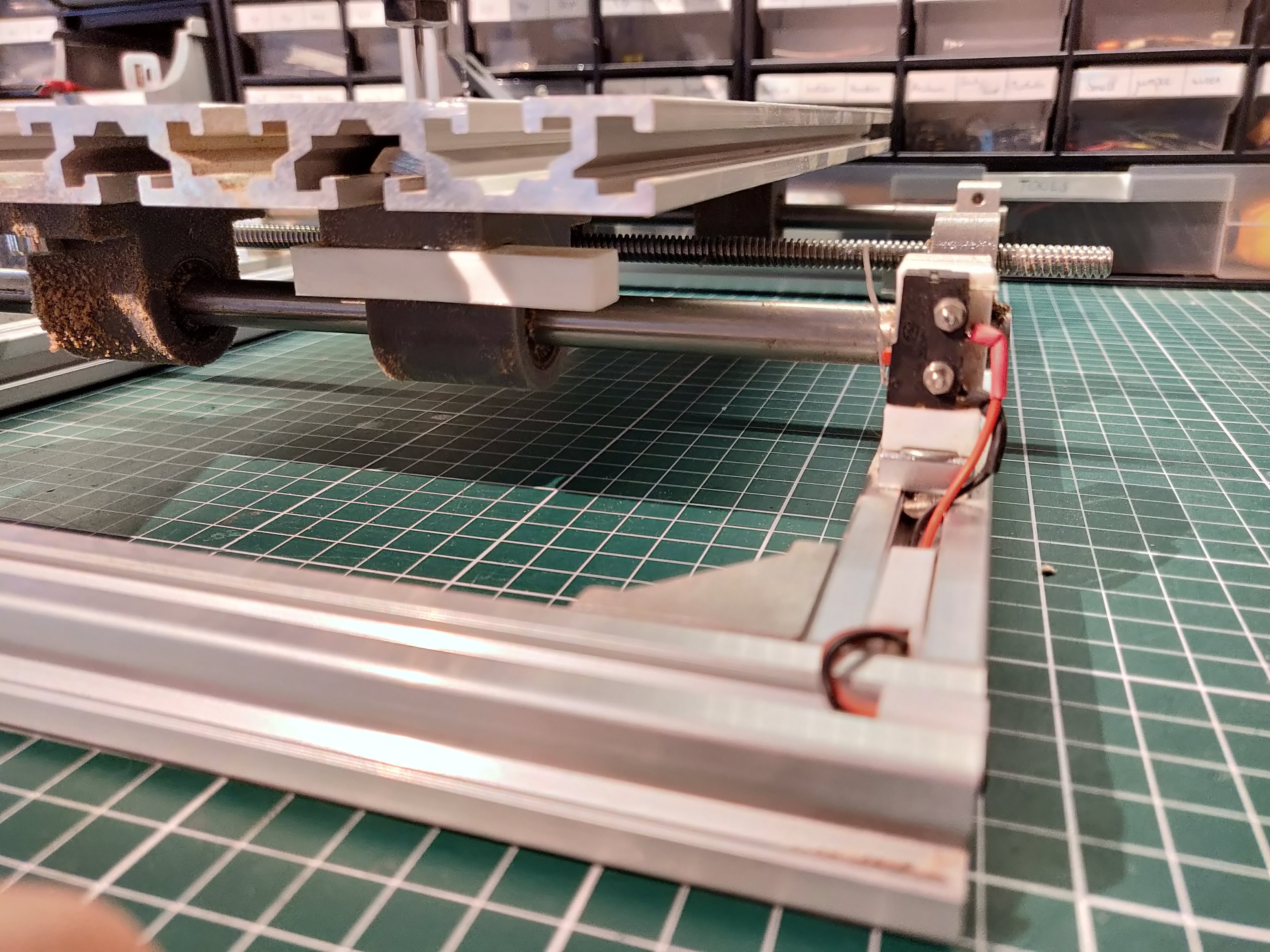
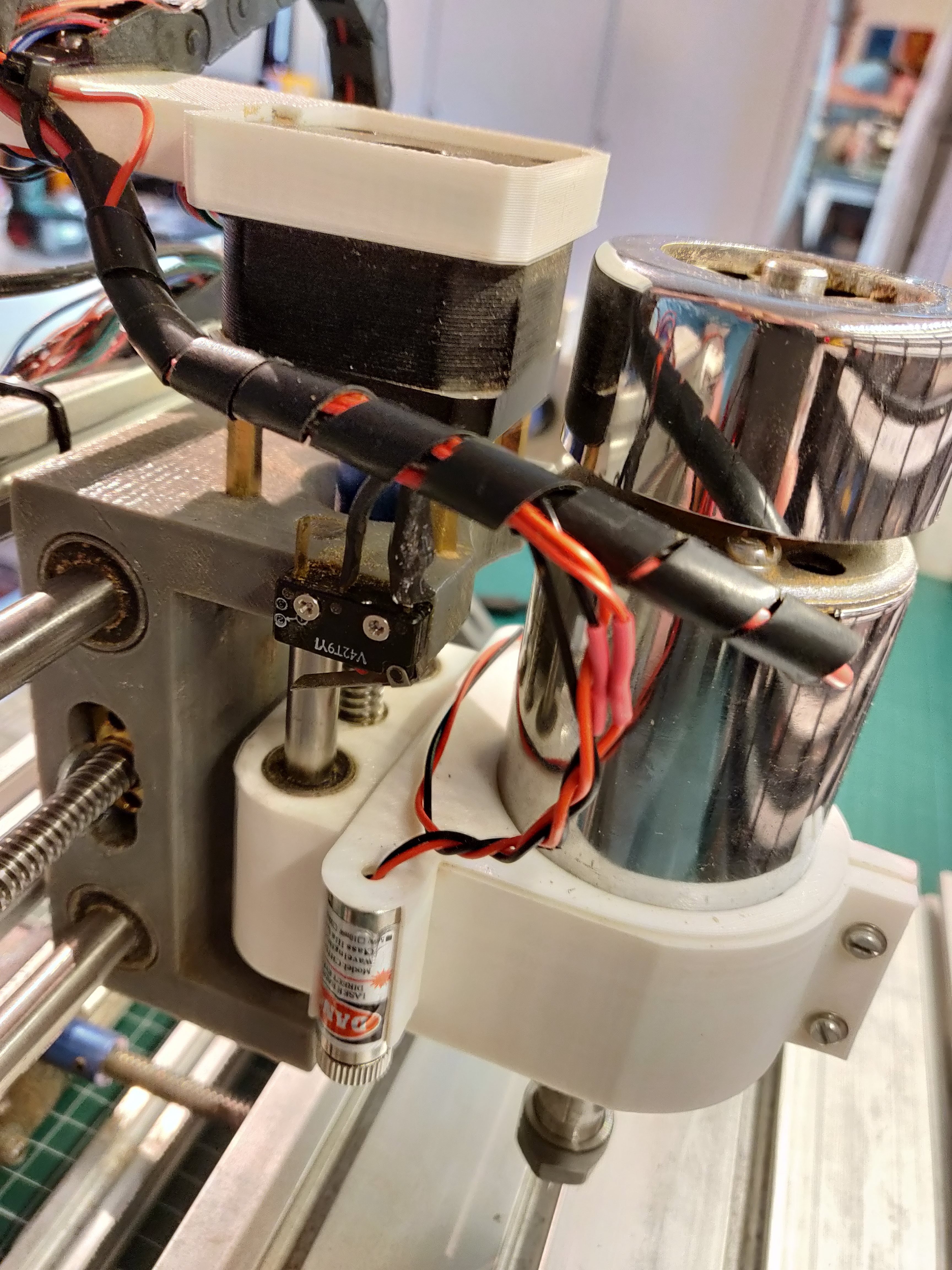
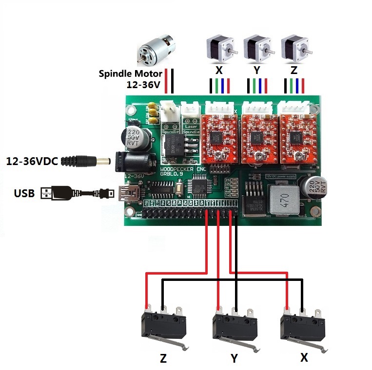
Now that the wiring is neat, we can start with the real upgrades. Homing switches will allow us to home the machine and soft limits will prevent from crashes.
Parts in this step
- 3 micro switches + M2 bolts
- Cables + dupont connectors
Homing switches
The X and Y limit switches are mounted on the brackets which hold the M8 rods by means of LimitSwitchHolder.stl. Print this piece twice and mount it on the locations indicated in the pictures.
The Z axis switch is simply screwed into the Z axis mount. Use one of the extra wires we ran through the dragchain in the previous step to connect this limit switch to the main board.
Solder a red and black wire to the limit switch and add dupont connectors to the other end. Plug them into the PCB according to the wiring diagram.
Updating GRBL
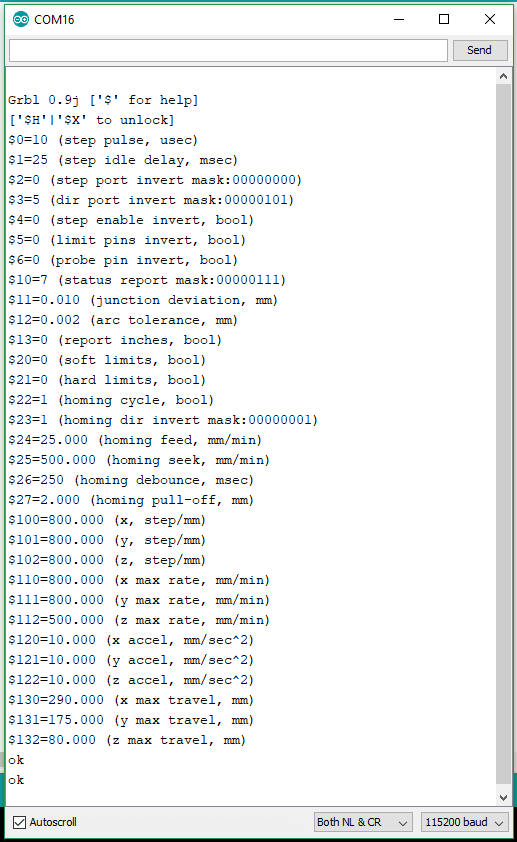
The homing switches and soft limits must now be enabled in the GRBL settings (GRBL is the software which runs on the microcontroller on the PCB). Soft limits prevent the CNC to crash into its own frame by halting moves which would cause a crash.
To do this, connect your CNC to a PC with a USB cable. Use the Arduino IDE (or any other terminal) to connect to the CNC by opening a new serial monitor (make sure you select the correct baud rate).
Type $$ to view the current settings
Type $22=1 to enable homing
Type $27=5 to adjust the homing pull off
Type $20=1 to enable soft limits
Type $130=300 to set the maximal x dimension (for CNC3018)
Type $131=180 to set the maximal y dimension (for CNC3018)
Type $132=40 to set the maximal z dimension
Type $$ again to verify the changes.
48V Spindle and Speed Controller
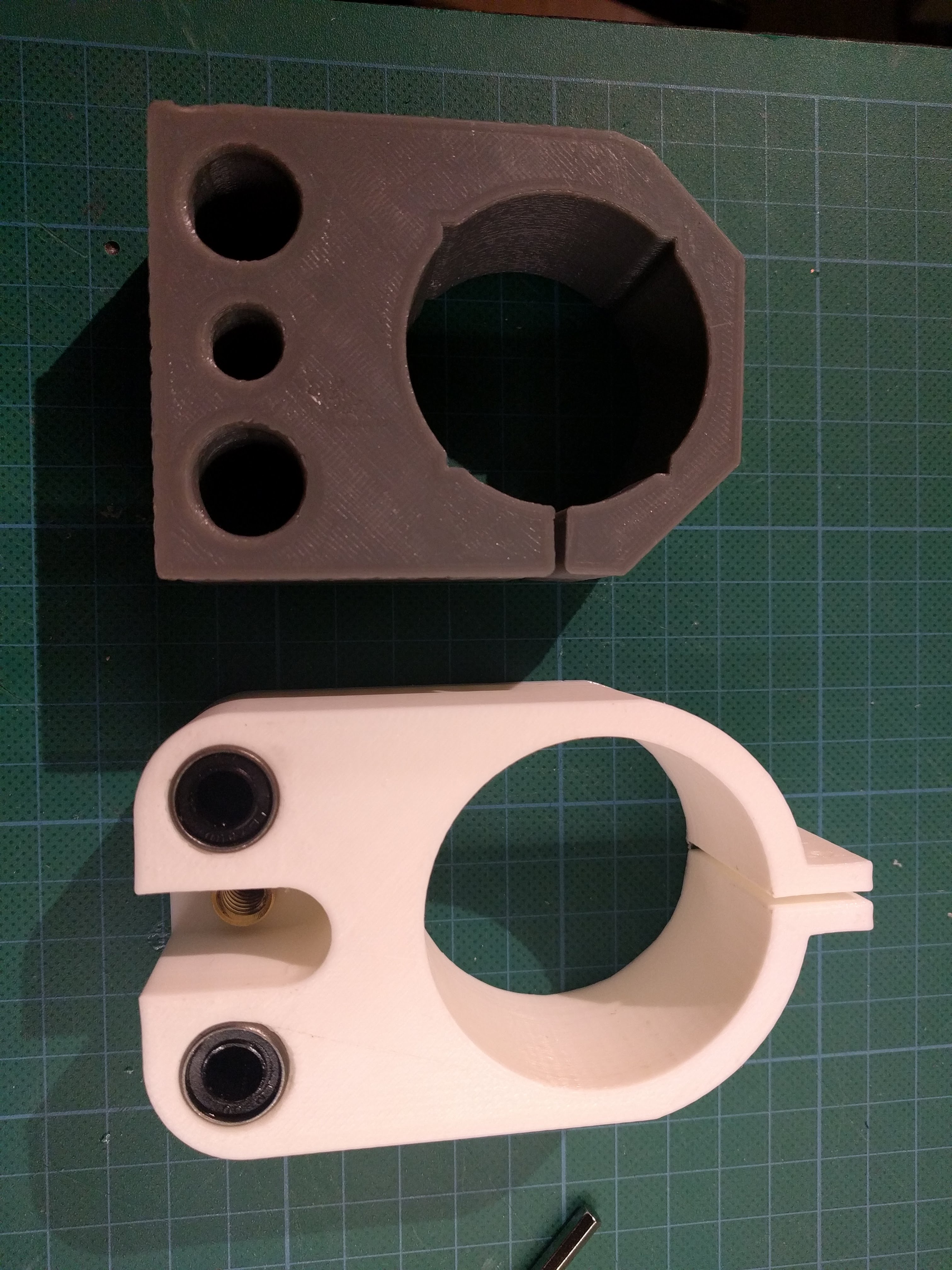
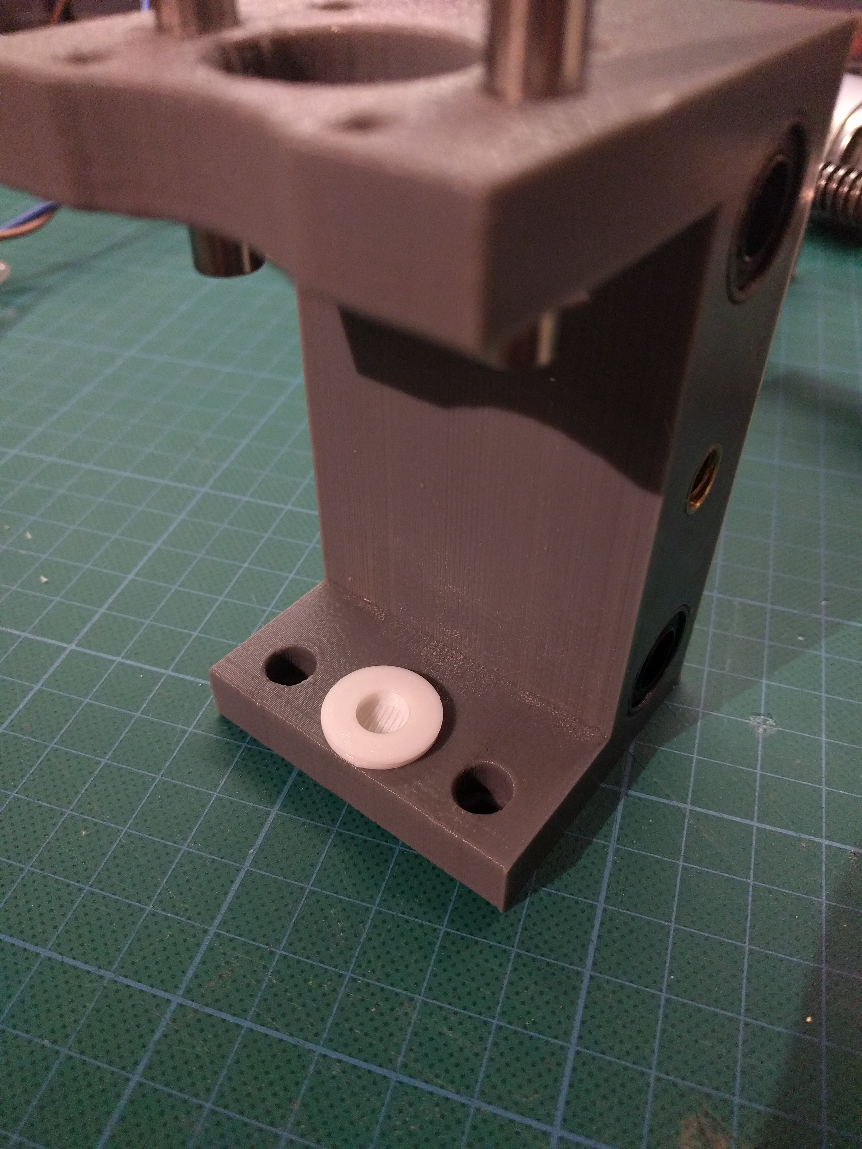
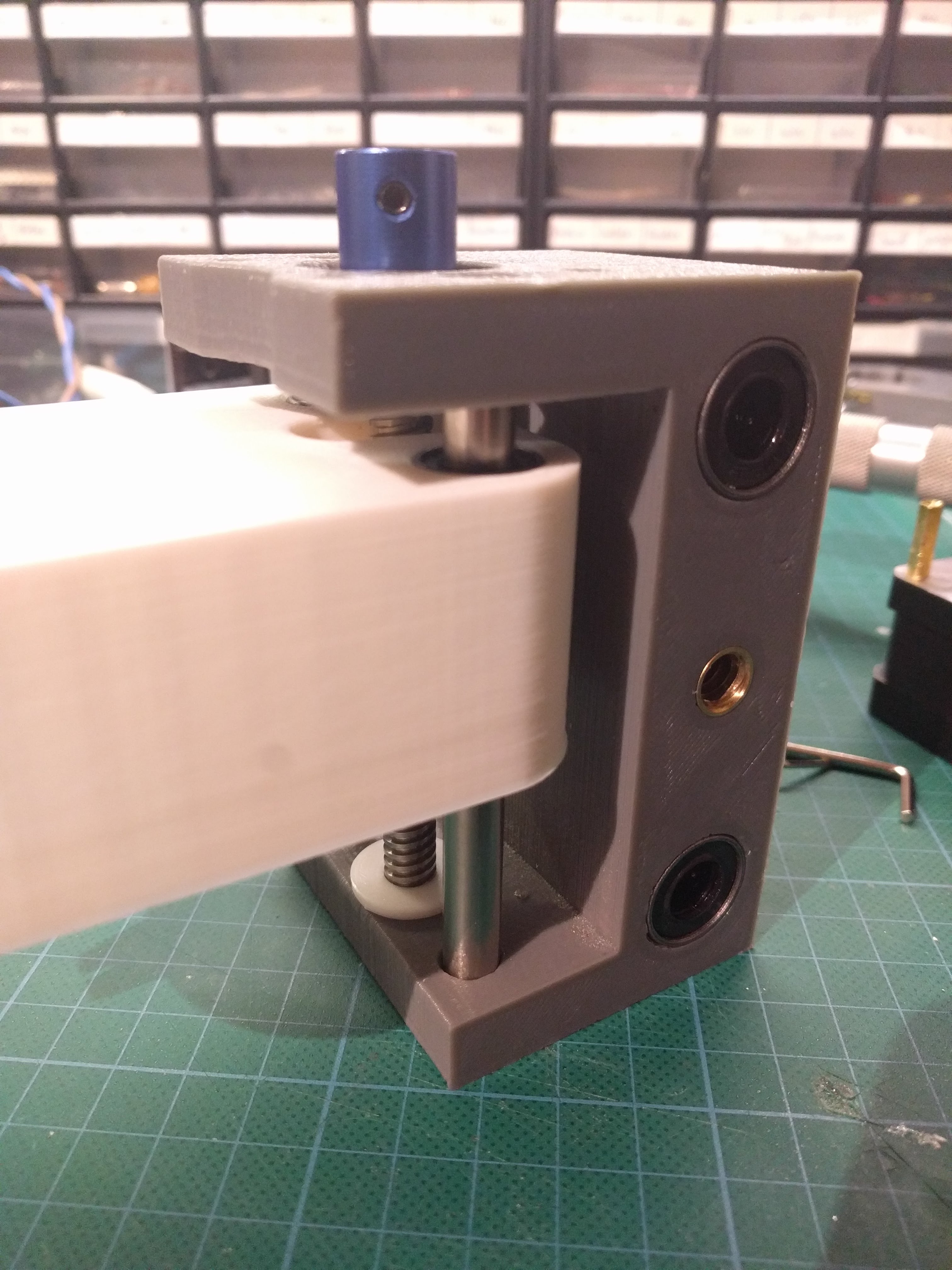
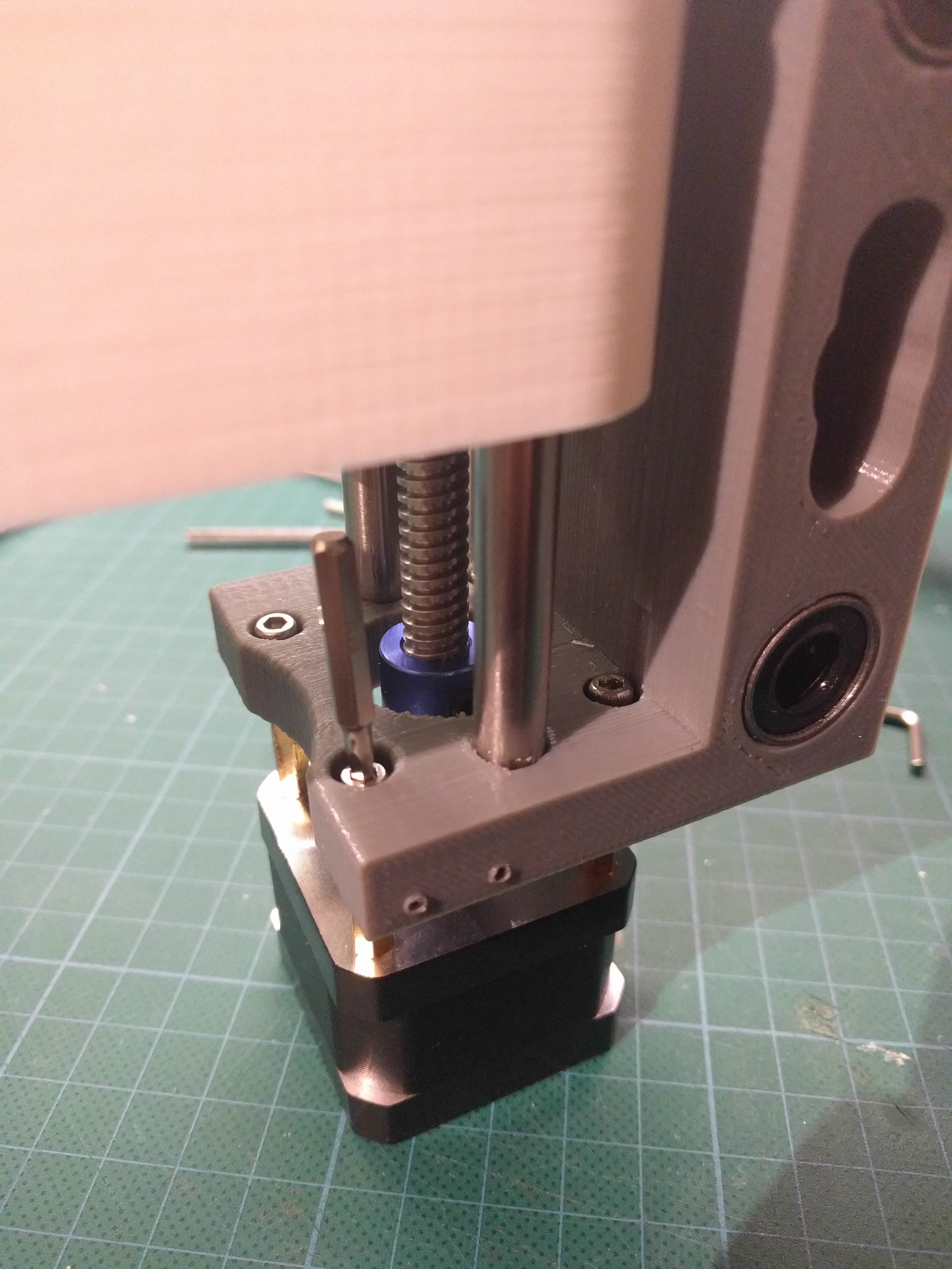
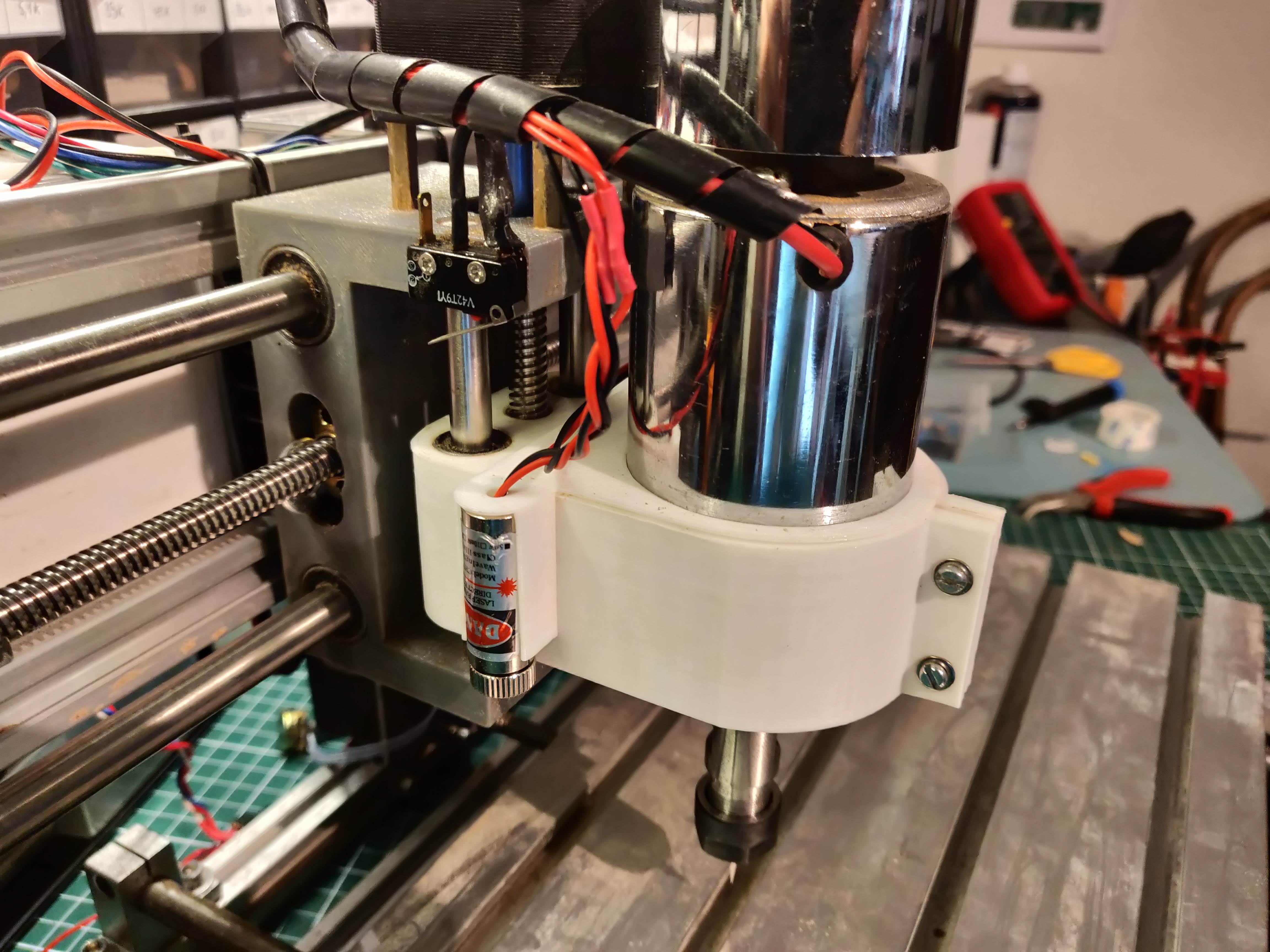
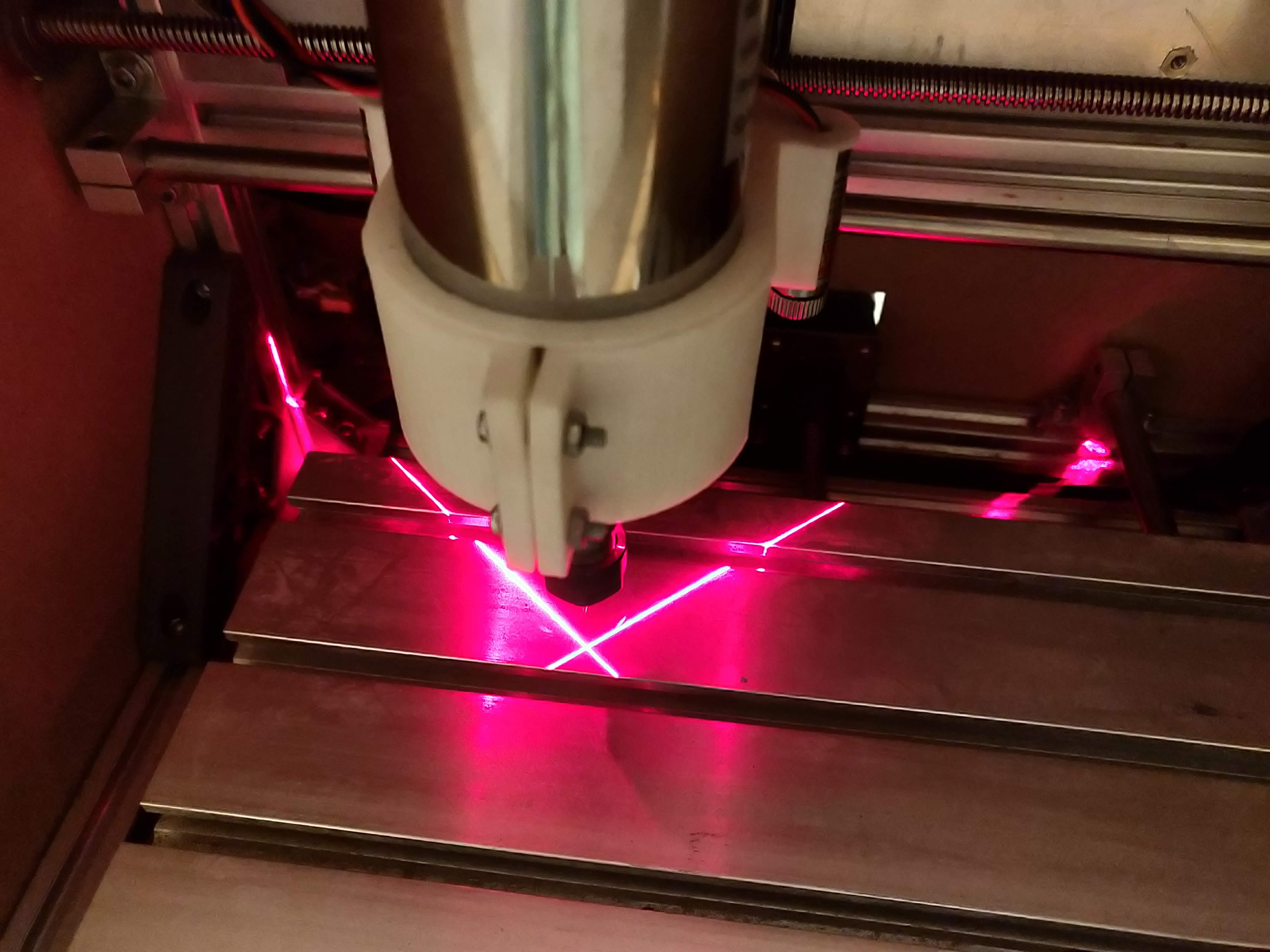
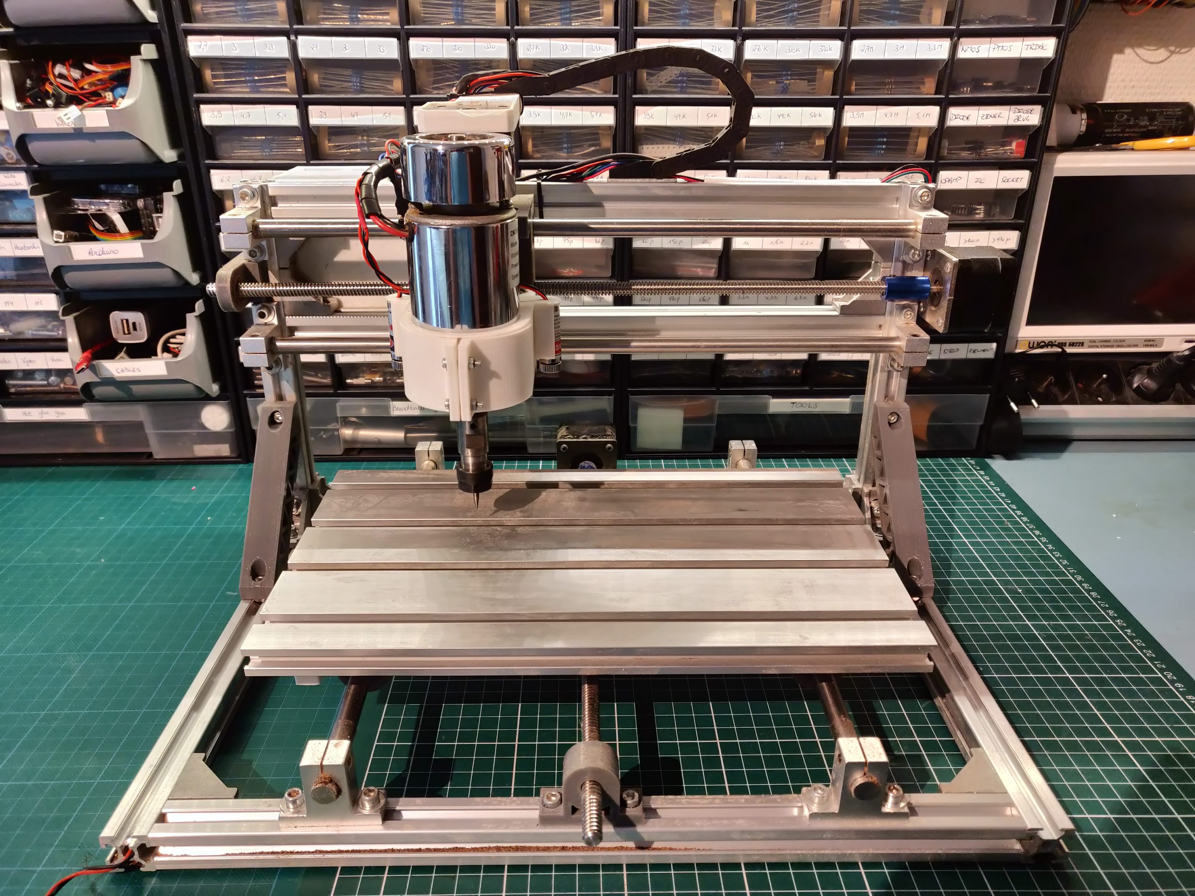
The spindle is one of the weakest points of this CNC machine. Upgrading it will allow us to cut aluminium quite easily! We will also add a speed controller, which is necessary for softer materials such as acrylic.
Parts in this step
- 300W 48V 52mm spindle motor
- 48 V power supply
- DC spindle speed controller
- Thick red and black wire
- Line laser modules
New Z axis spindle mount
To accommodate the large spindle, we will have to make a new spindle mount. Start by taking apart the original carriage: remove the stepper motor, leadscrew, M8 rods and spindle mount. Print Spindlemount.stl, SpindlemountLaser.stl and Z_leadscrew_stop.stl and reassemble the carriage according to the pictures. Finally, mount the carriage back on the CNC and insert the new spindle motor.
At this point, we can also add 2 line lasers to indicate the position of the router bit. Install them in holders and connect the cables to the remaining wires we routed through the drag chain.
Add the powersupply and speed controller
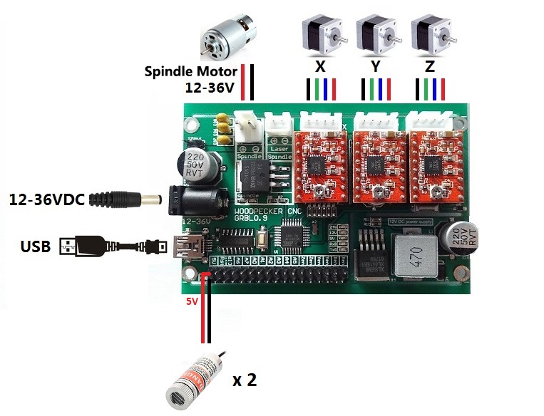
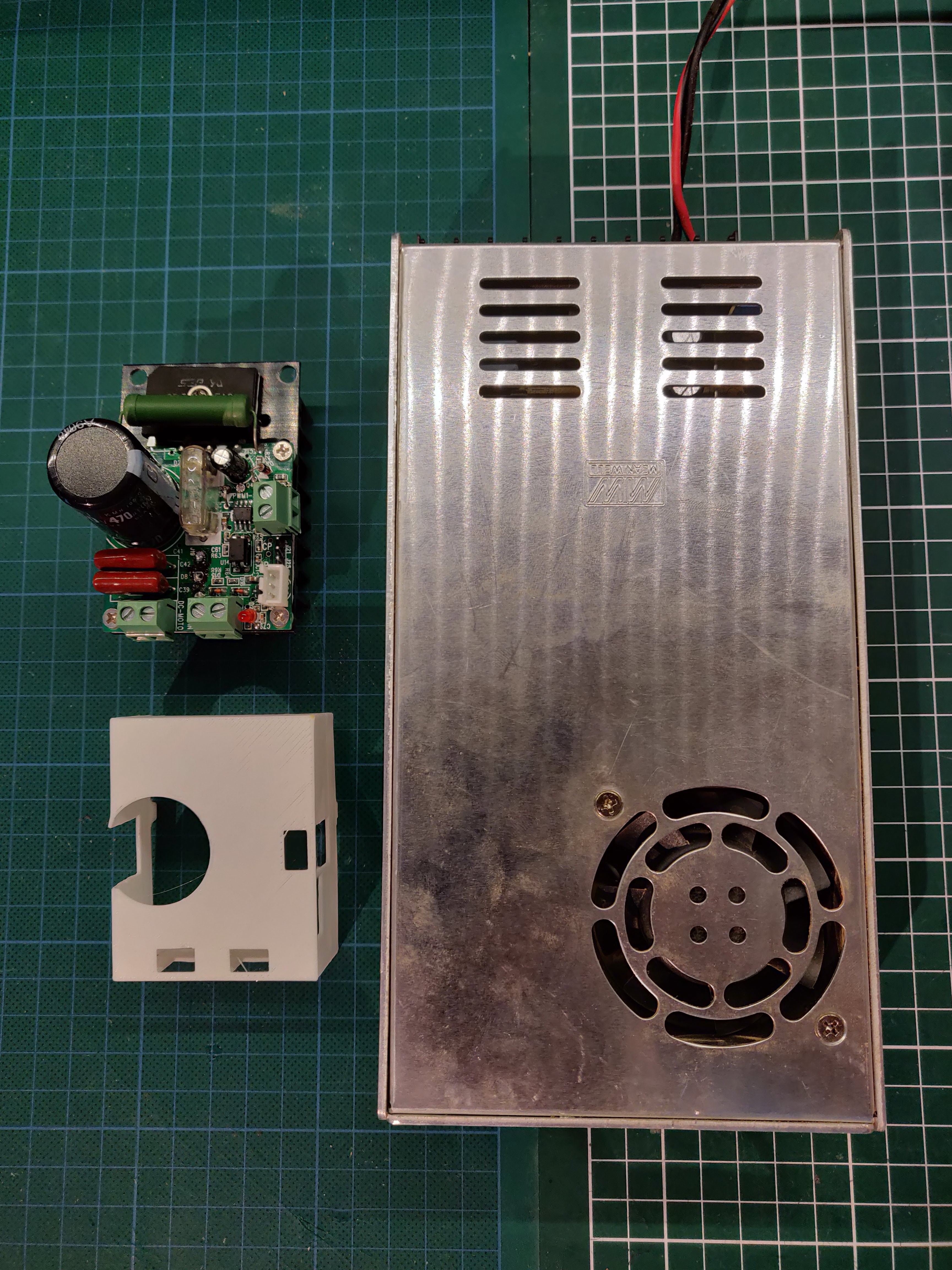
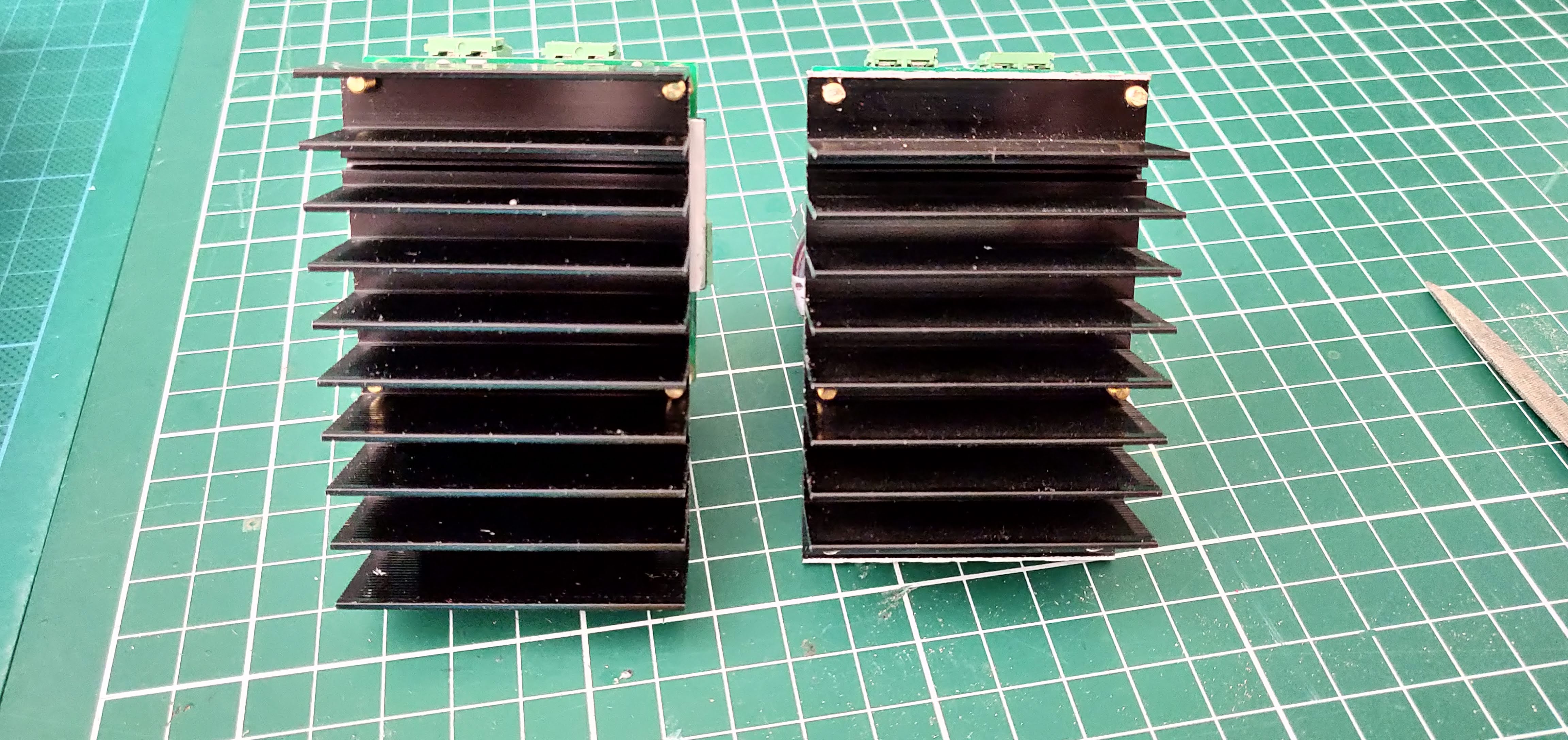
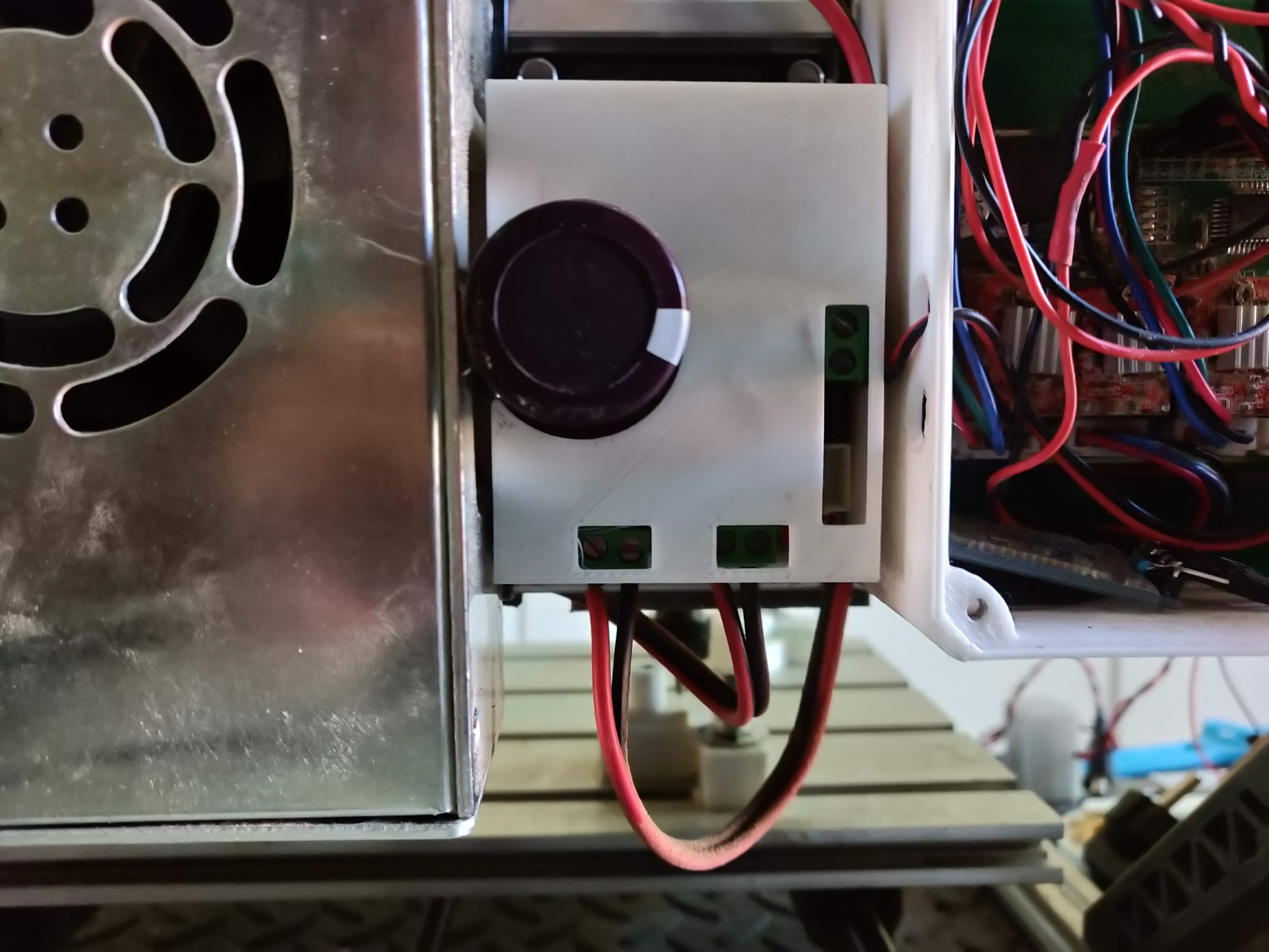
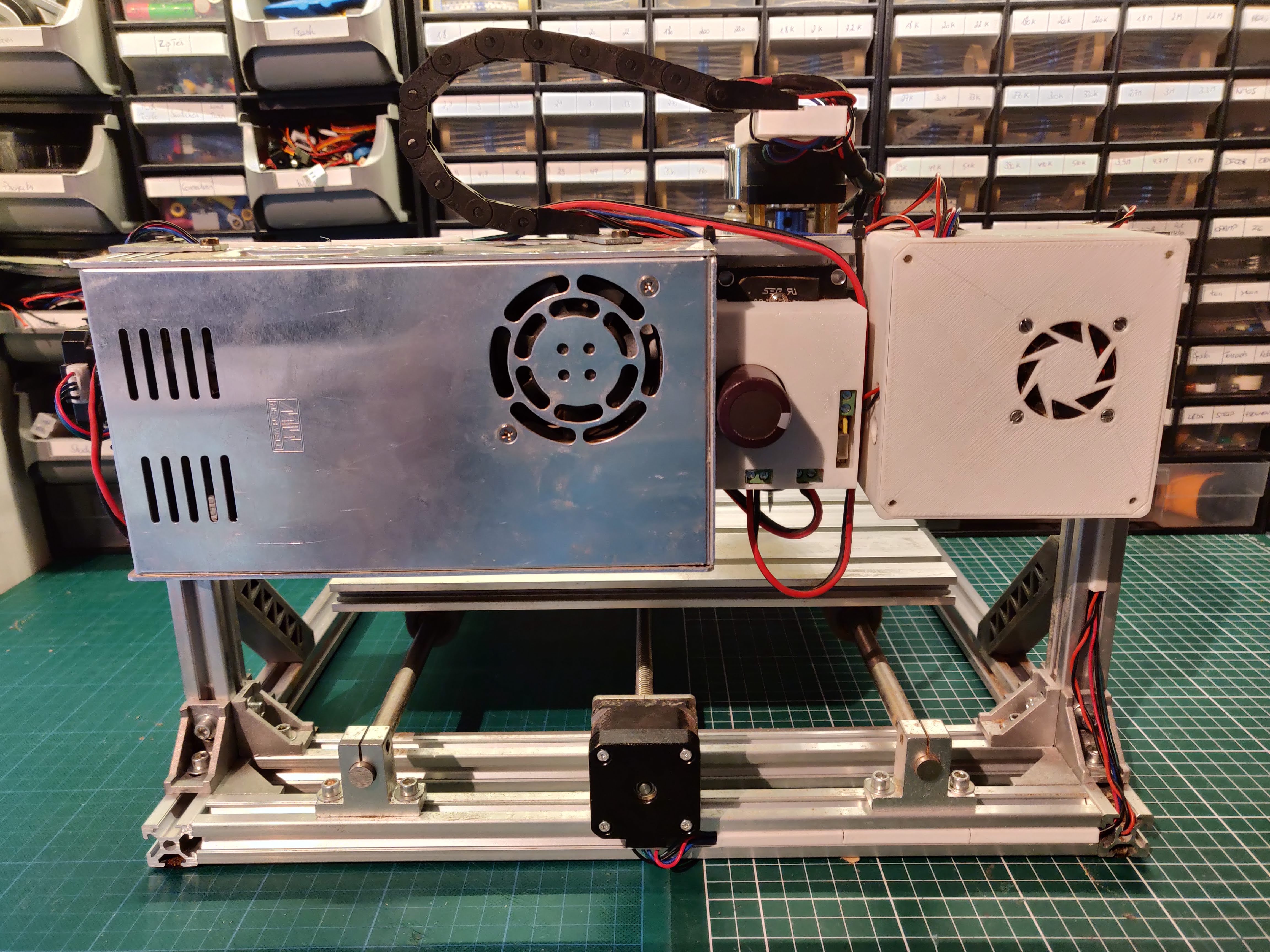
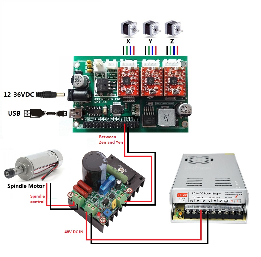
We can now install the 48V powersupply on the back of the CNC with some screws. To mount the speed controller, I removed the 2 outer fins of the heatsink, such that it fits perfectly in between the aluminium frame. Print MotorControllerBox.stl to cover the speed controller. Wire the speed controller according to the diagram.
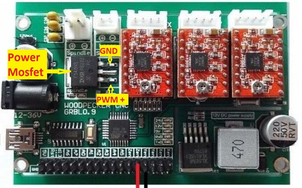
Some versions of the woodpecker PCB might not have the PWM motor speed control signal brought out to the header pins. In that case, you can solder the wires directly to the original motor control MOSFET, as shown in the last diagram.
By changing the motor controller, the motor might not turn when the speed setting from candle is too high. This has to do with the PWM signal that is generated. To get around this, decrease the speed setting in candle. Another option would be to change the GRBL max speed value via the $30 command.
Emergency Button and Z Probe
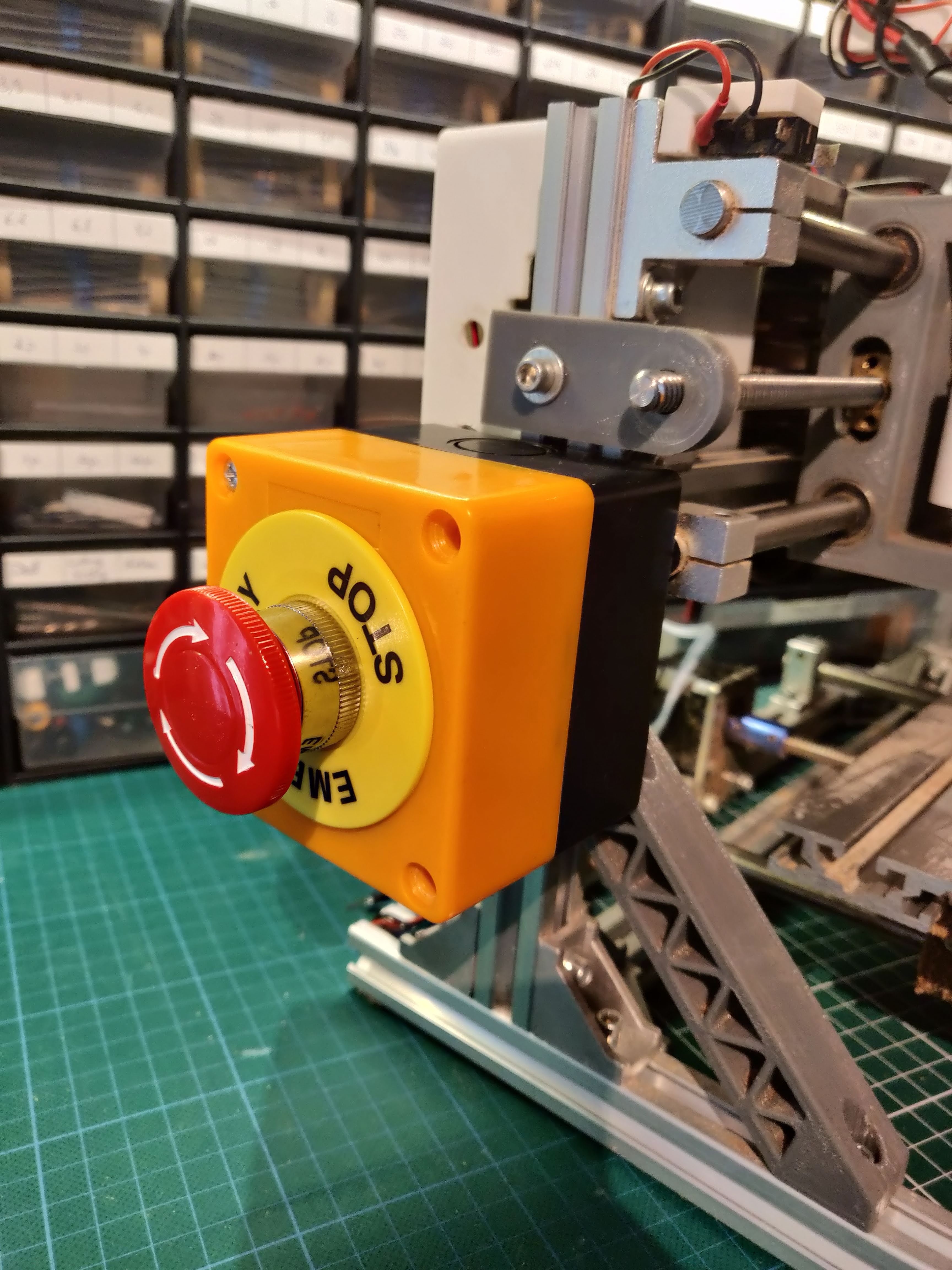
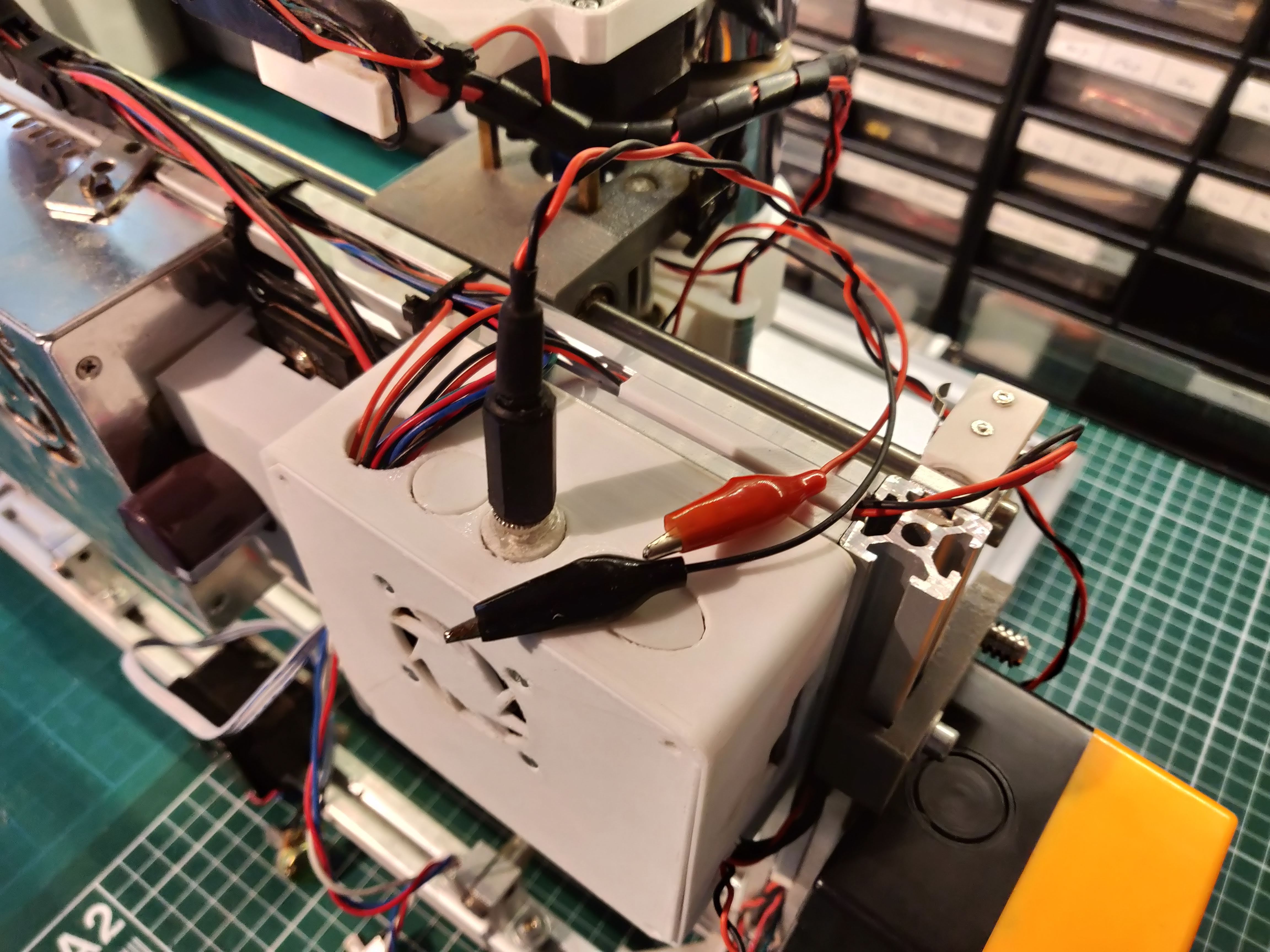
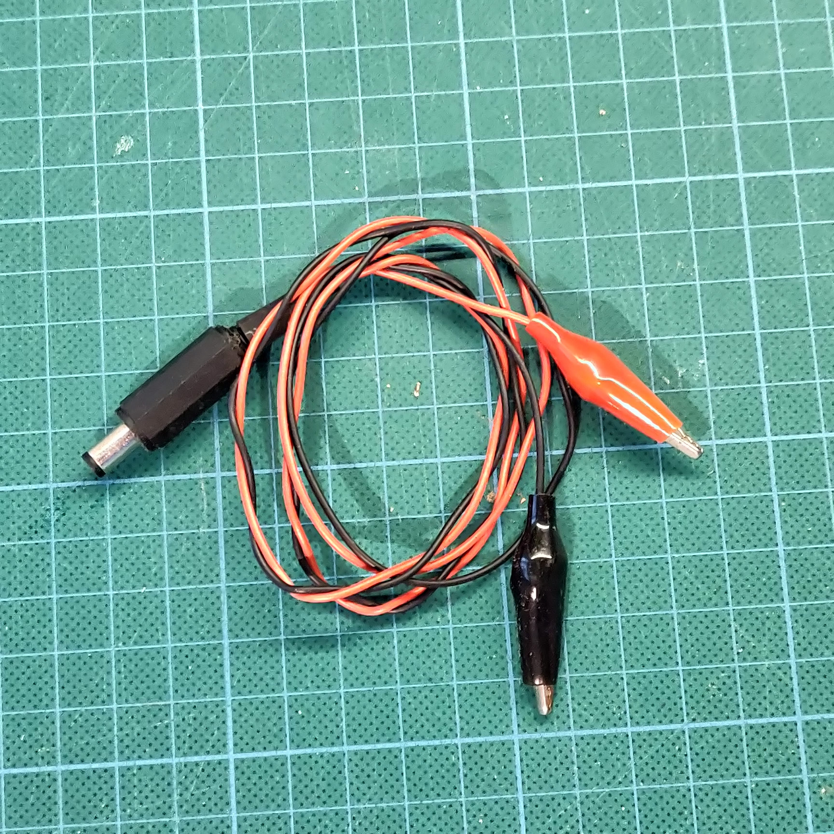
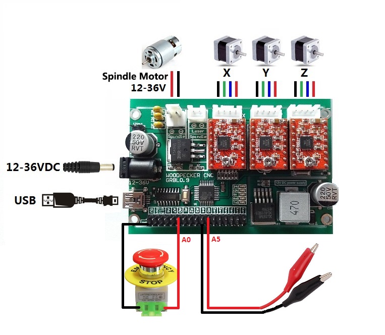
Two more features are essential for a full-fledged CNC machine: an emergency stop button and Z probe.
Parts in this step
- Emergency button
- Cables + dupont connectors
- Crocodile clips
- DC barrel jack and receptacle
Emergency Stop Button
Emergency stop buttons can cheaply be bought online and provide a very useful upgrade. Sooner or later your router bit will crash into your material or CNC in a way you didn't intend. Stopping your machine is essential for the safety of you and your machine.
Solder wires to the Normally Open side of the button and the other side to dupont headers. Then, connect it to pin A0 of the main board.
Z probe
Z probing allows you to probe the height of your workpiece. This makes it more easy to set the height of your router bit and allows for making so-called height maps, which are essential when milling PCBs. Since we don't need this all the time, we will connect the Z probe via a DC jack.
The first cable goes from a female DC jack to dupont wires and is connected to pin A5. A male DC jack can then be soldered to two crocodile clips. One is attached to the bit, while the other one is clipped to a (metal) workpiece, like a PCB.
Manual Control
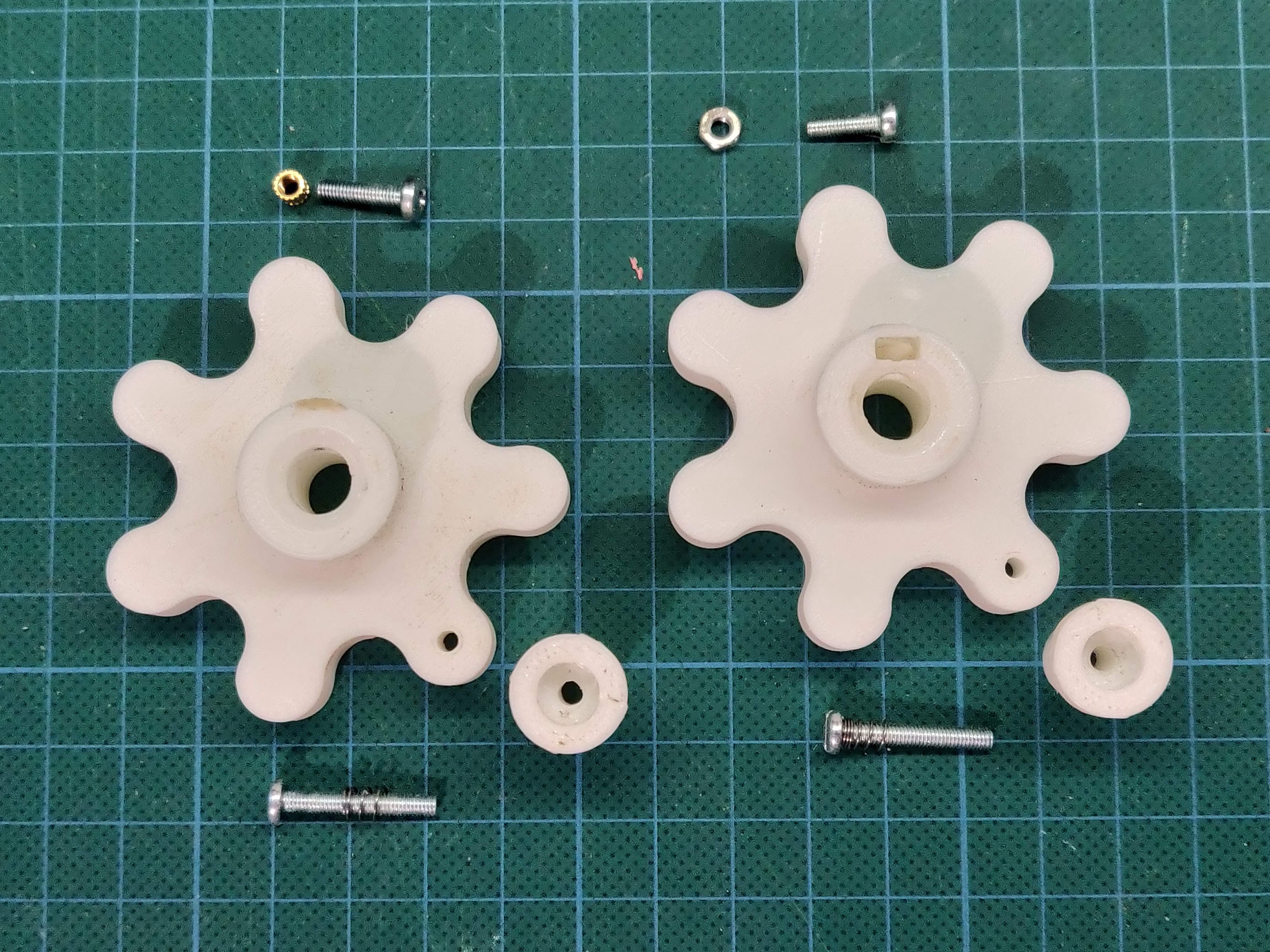
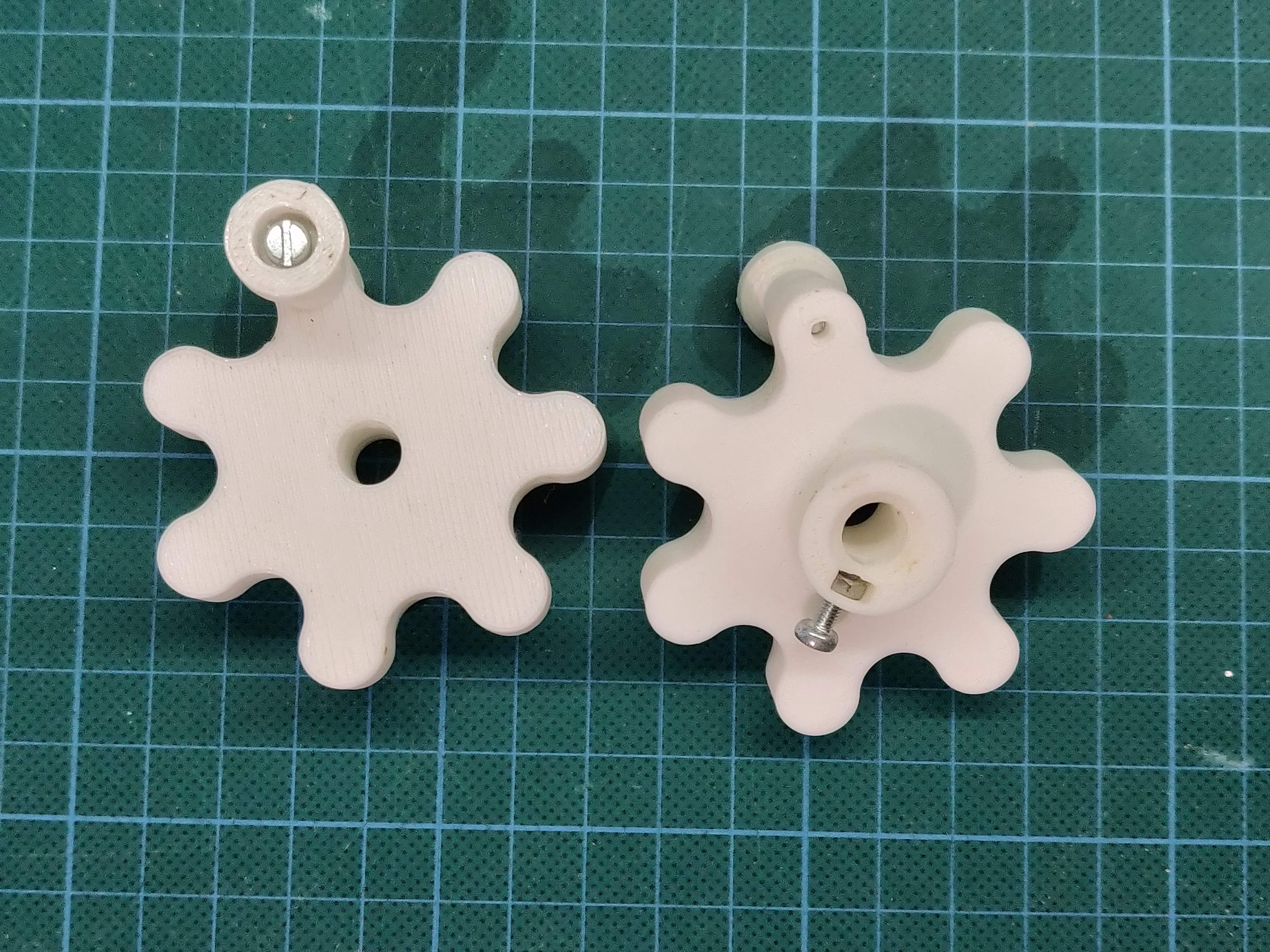
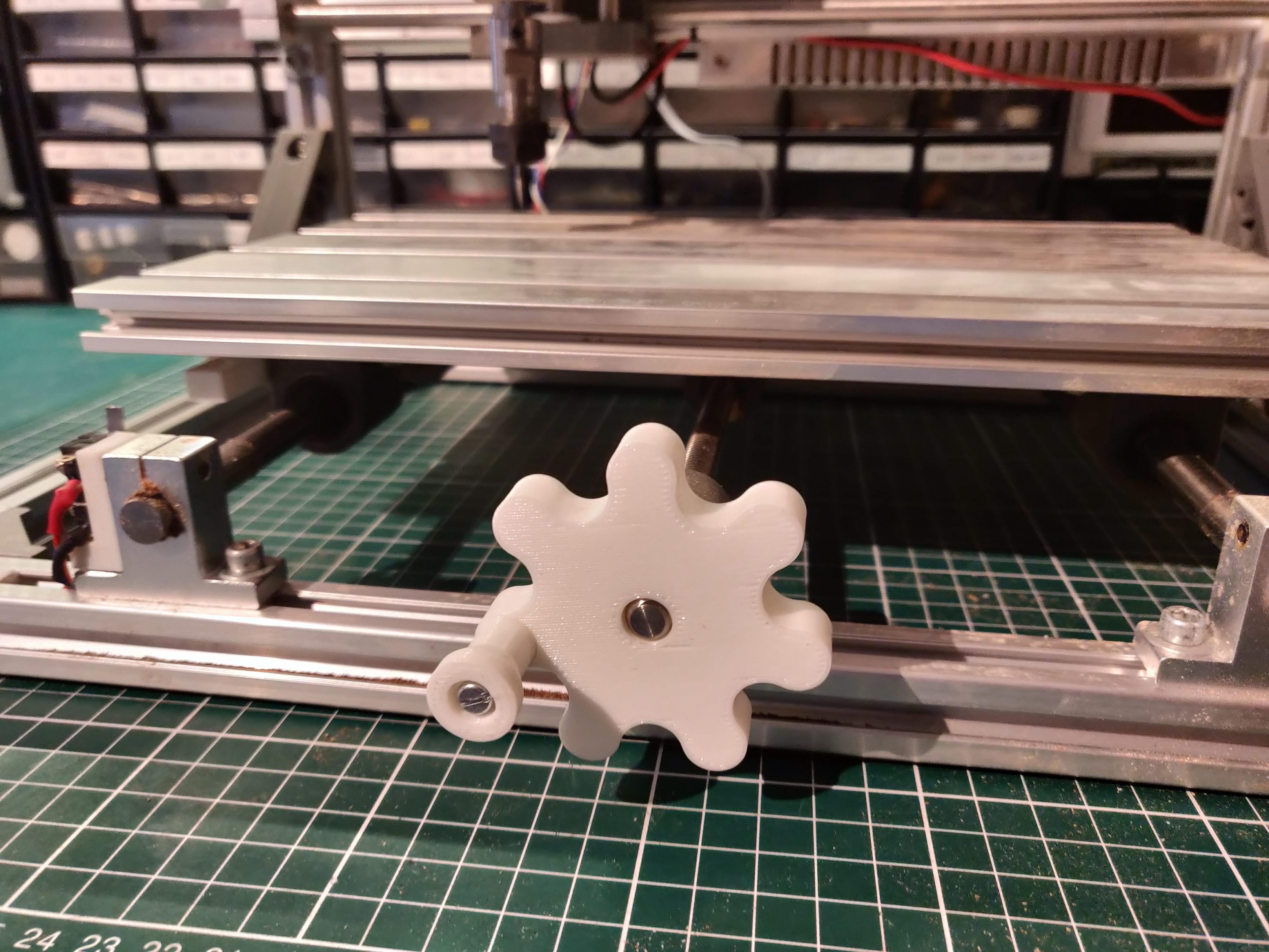
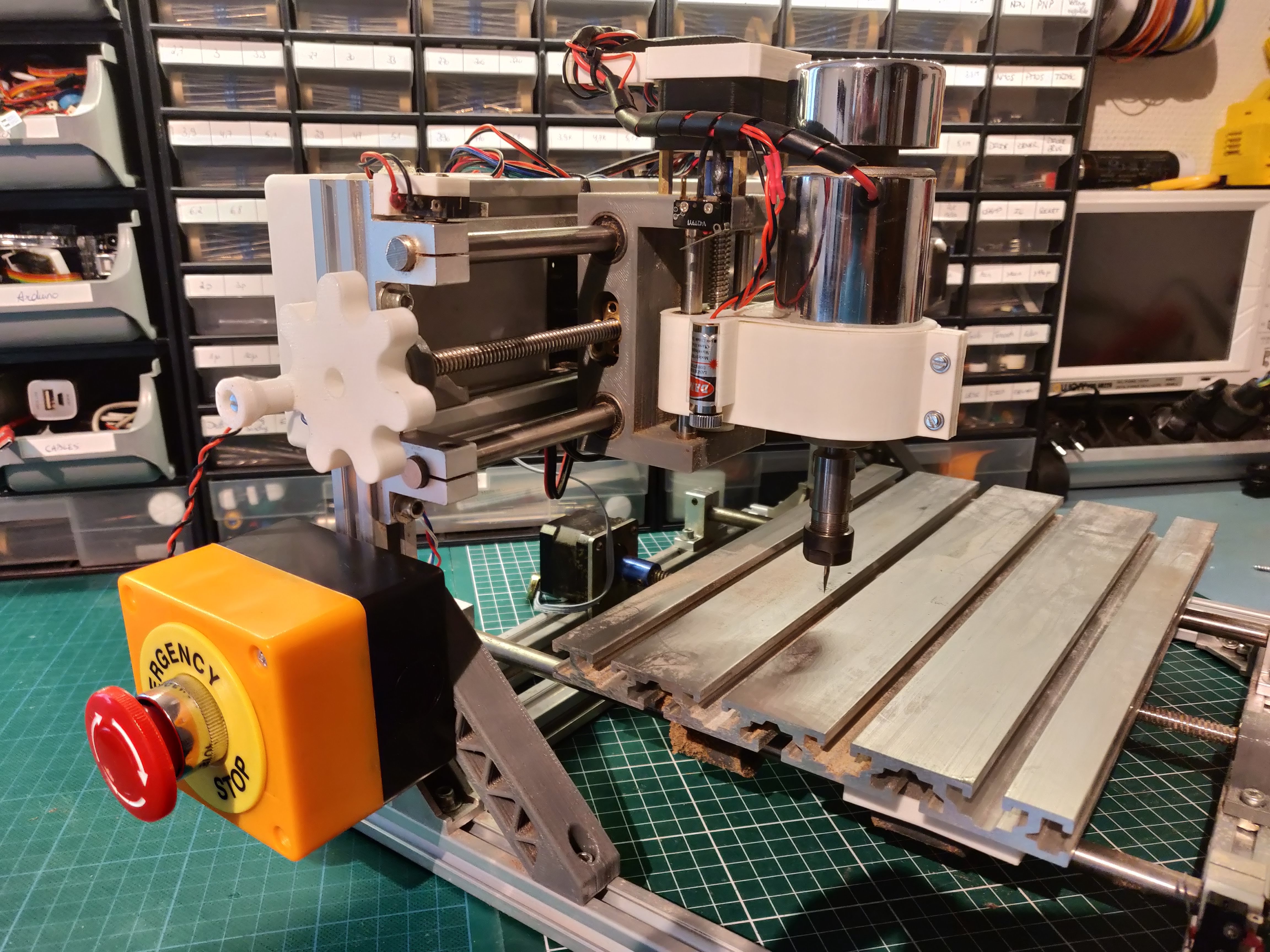
CNC stands for Computer Numerical Control, but in some cases manual control is beneficial. Therefore, we'll add knobs to the X and Y axis.
Parts in this step
- M3 screws
- M3 nut or threaded insert
Making the knobs
First, print the handles. If you plan on using threaded inserts, print CNChandleInsert.stl; otherwise print CNChanleNut.stl. Both options are shown in the picture. Also print CNChandlehandle.stl and assemble the pieces. Install them on the X and Y lead screws of the CNC machine.
Bluetooth Control
As a final modification, I added bluetooth control to the CNC. This allows me to control it through my phone, but is a more advanced step and completely optional. I use the G-code2GRBL android app.
Parts in this step
- HC-05 bluetooth module
- 1k Ohm and 2k Ohm resistors
- Switch
Hooking up the bluetooth module
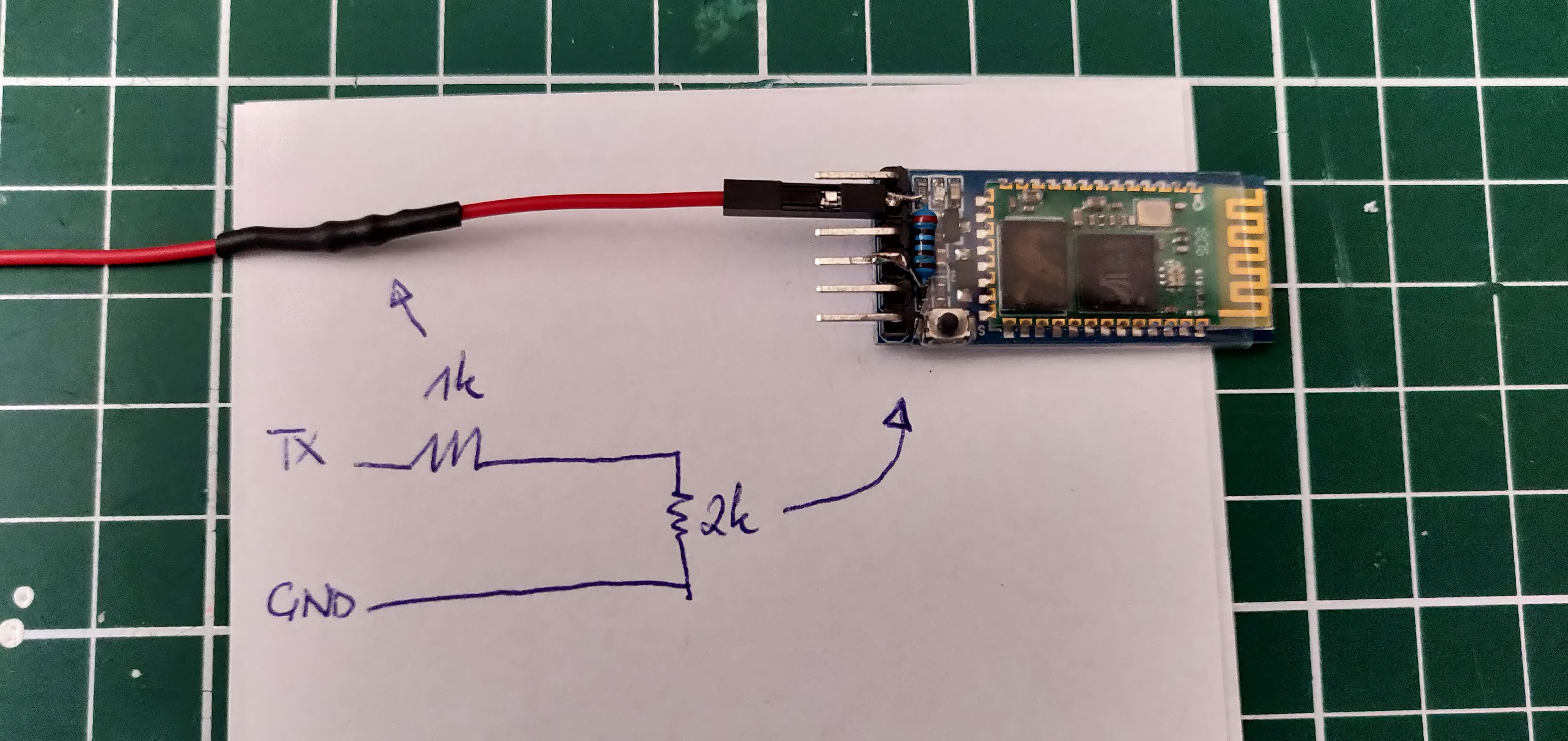
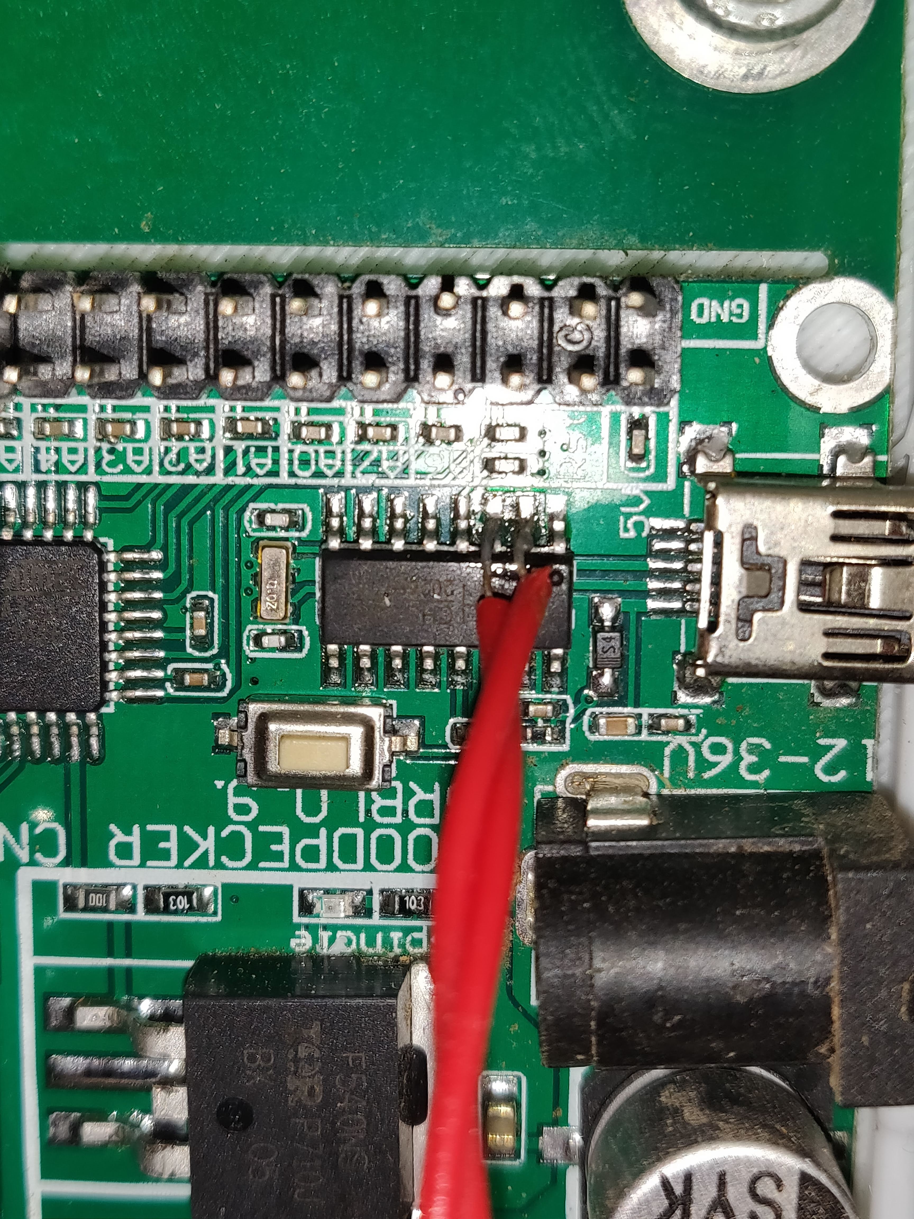
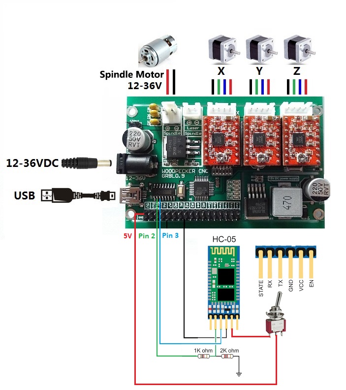
The HC05 bluetooth module should be connected to the TX and RX pins of the microcontoller. Since the module is 3V3 rated and the microcontroller runs at 5V, a voltage divider is added between the TX pin of the microcontroller and RX pin of the bluetooth module. Furthermore, a switch is added to disable the module, as it otherwise intervenes with the USB communication. Hook up everything according to the diagram.
Case
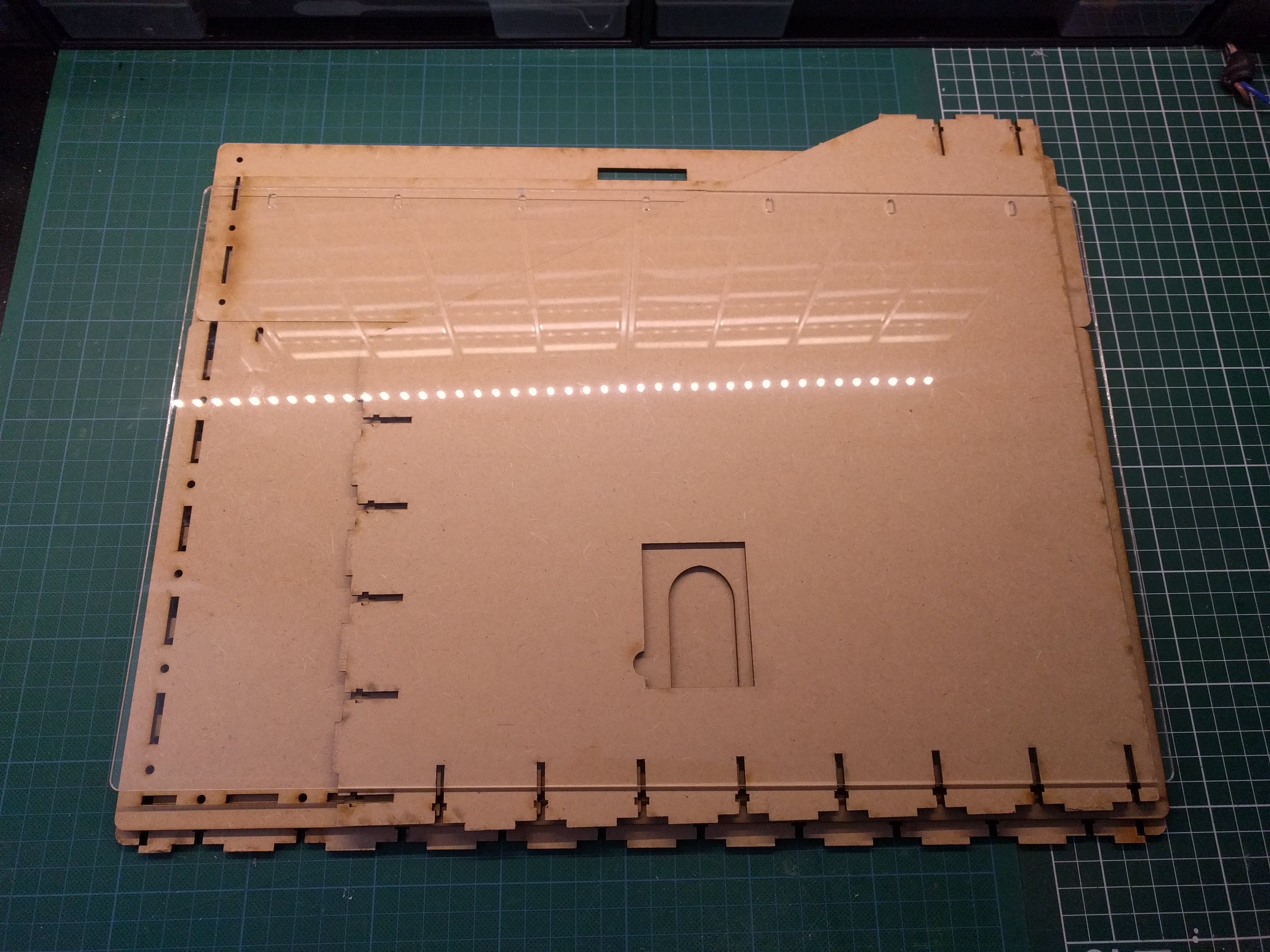
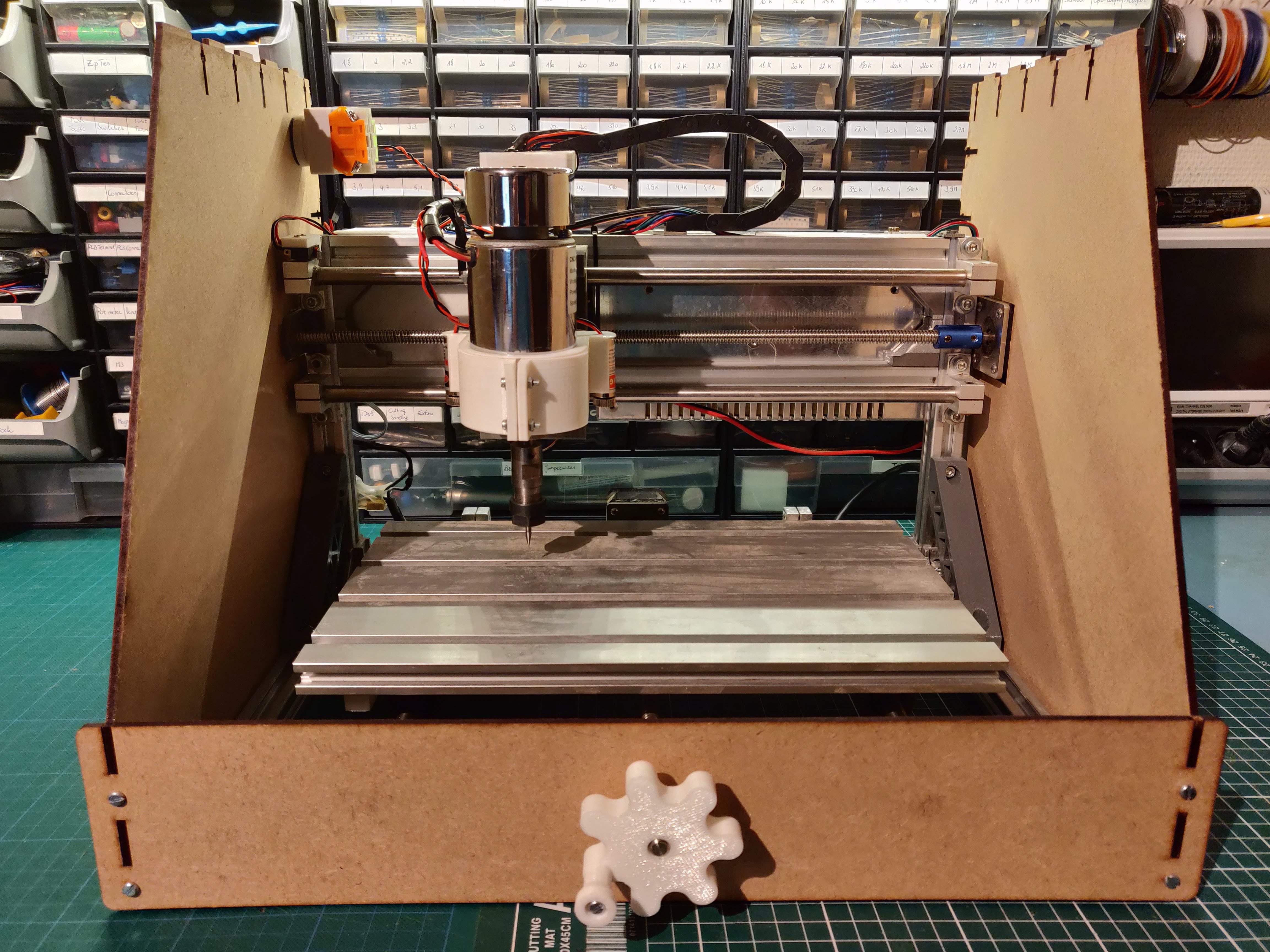
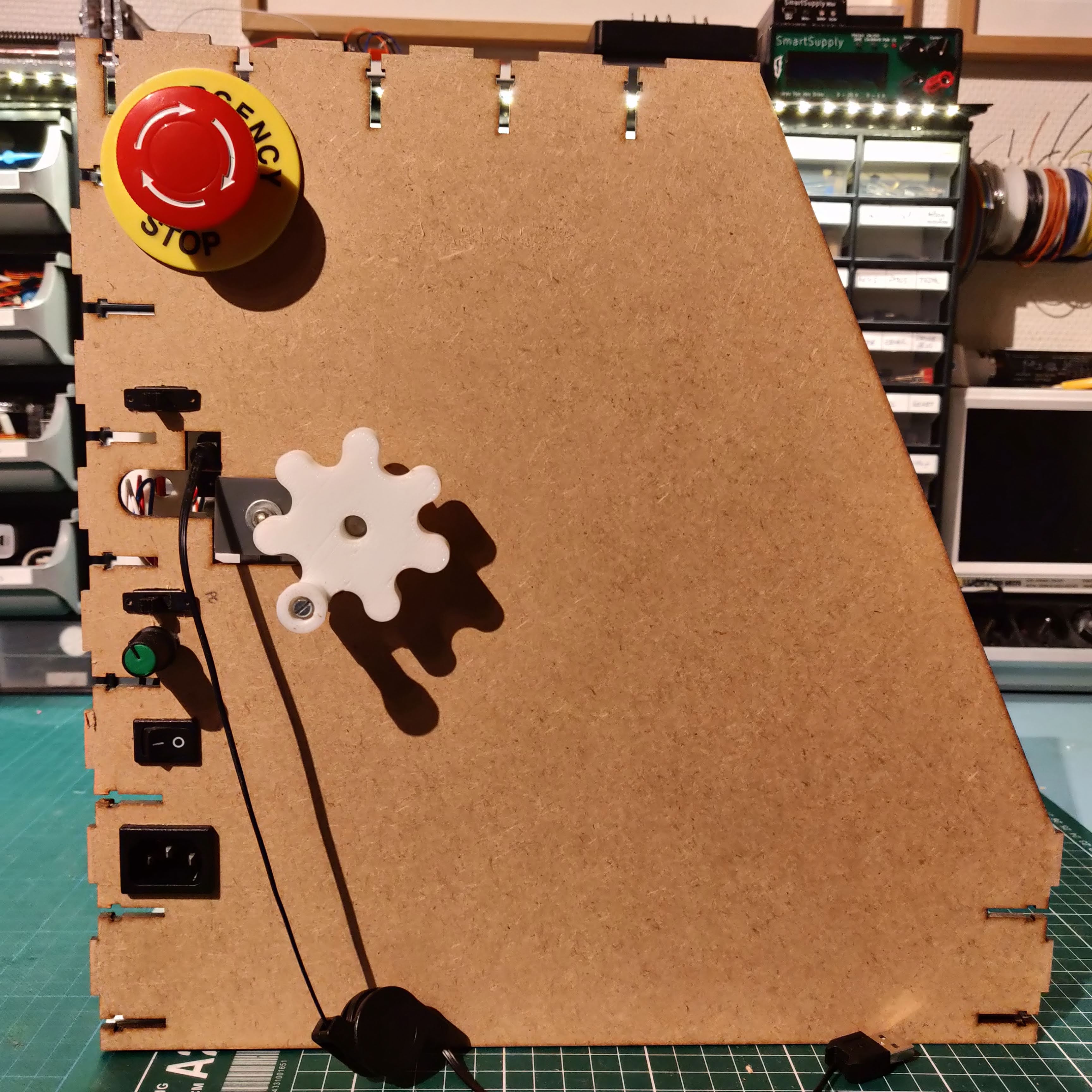
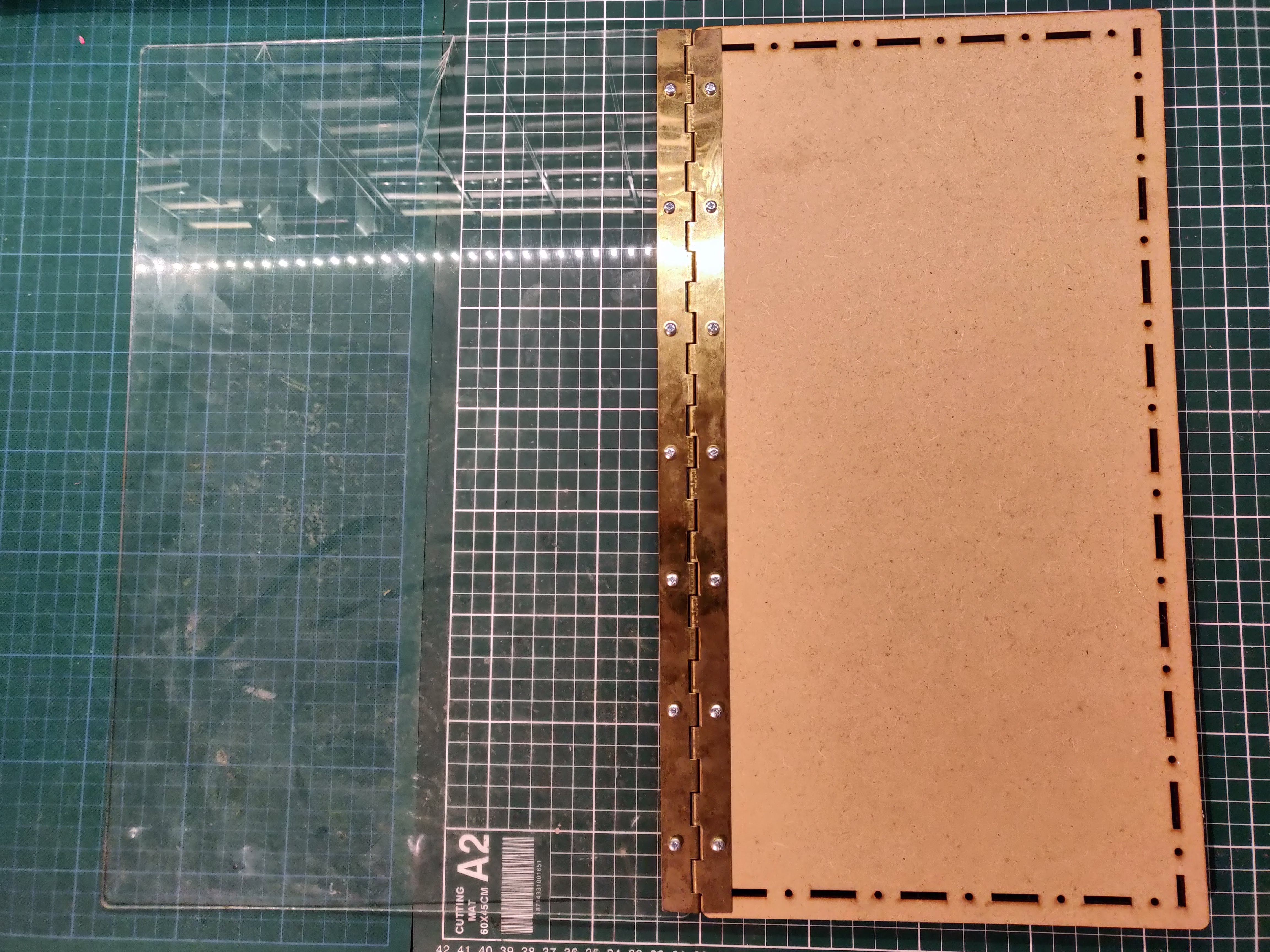
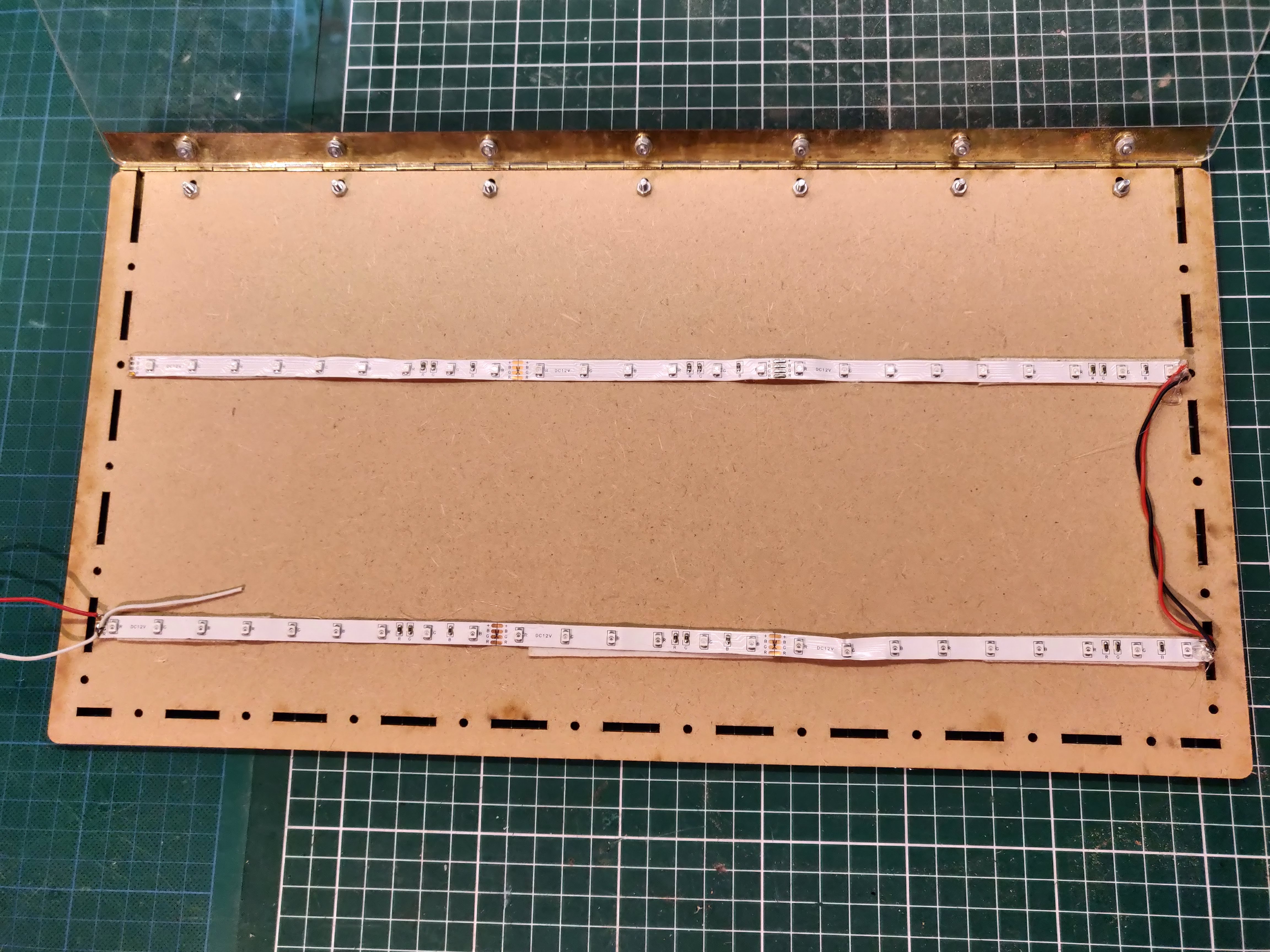
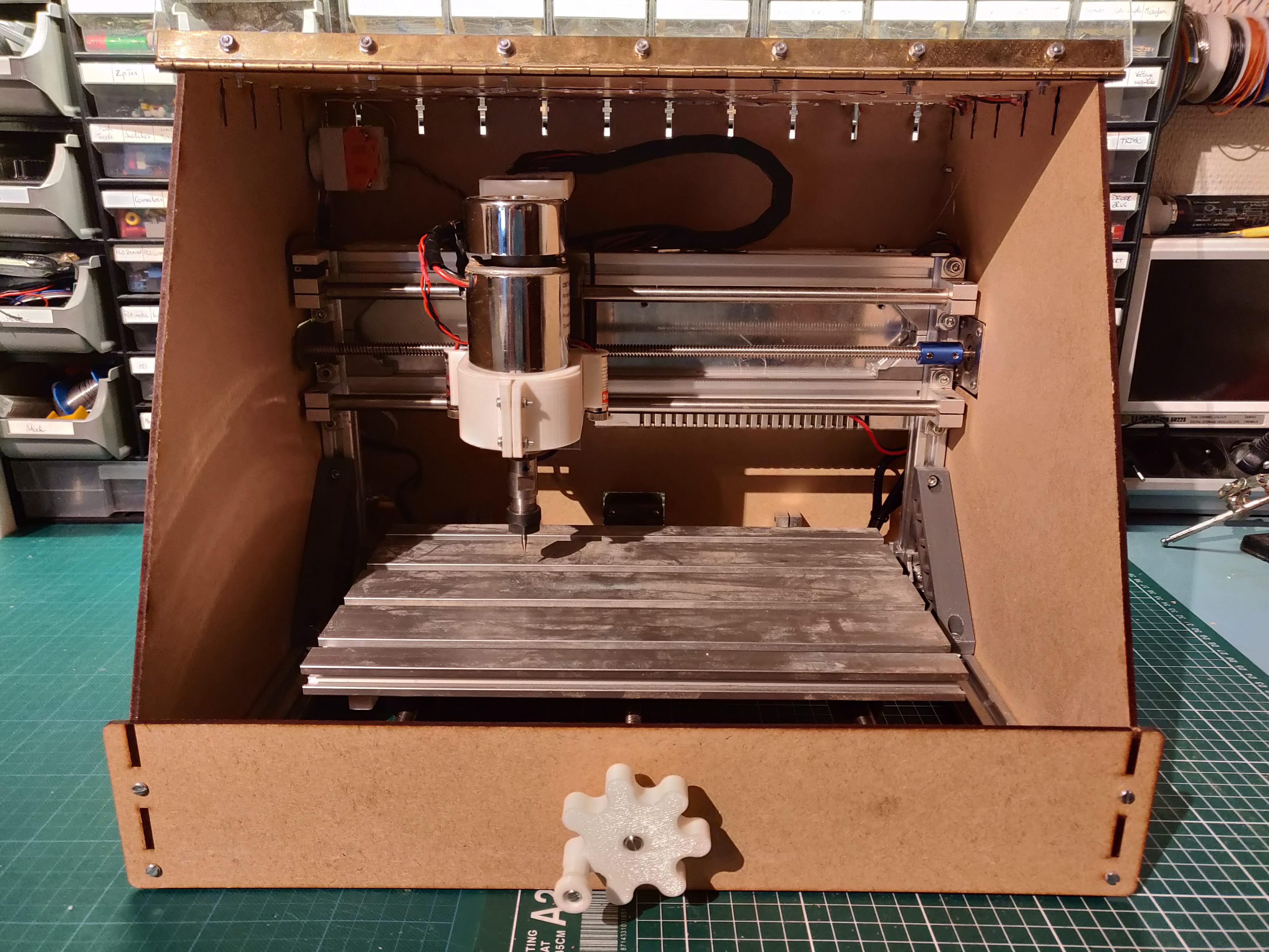
We now have a CNC machine with a lot more capabilities. As a final touch, we will give it a nice case to keep dust and sound under control. It will also make it look neat and professional!
The case is designed to be laser cut; I used 3 mm MDF for all sides and the top, and acrylic for the lid.
The files are specifically for the CNC3018 and will not fit the smaller variants! However, the fusion 360 file is included such that you can adjust it to your needs.
Parts in this step
- IEC socket with switch
- M3 bolts and nuts
- LED strip
- Carbon filter
Assemble the front and sides
First, add the sides and front to the CNC and bolt them together. The manual control knobs and emergency switch can also be added at this point. An IEC inlet and switch are installed for the 48V spindle powersupply.
Assemble the lid
Next, connect the top to the lid with bolts and nuts. Add an LED strip to the underside of the lid and plug it into the 12V supply on the main board.
Assemble the back
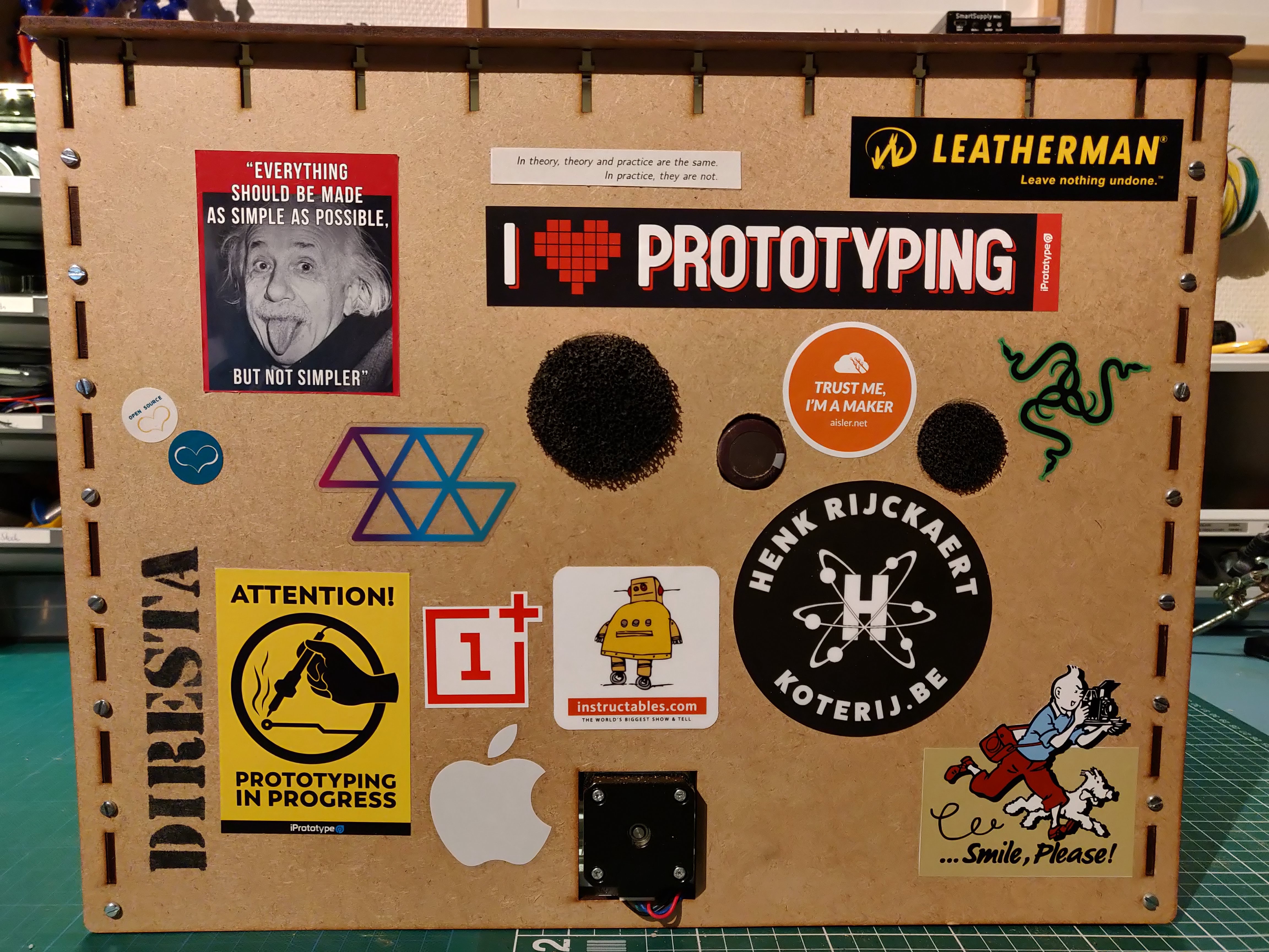
The back of the case has cutouts for the air inlets, to which a piece of carbon filter is added. To prevent dust from leaving though the Y axis stepper motor cutout, print StepperCover.stl and snap it in place.
Lastly, connect all the wires to the main board and close the enclosure for the electronics. The back can now be bolted in place to finish the case.
Enjoy
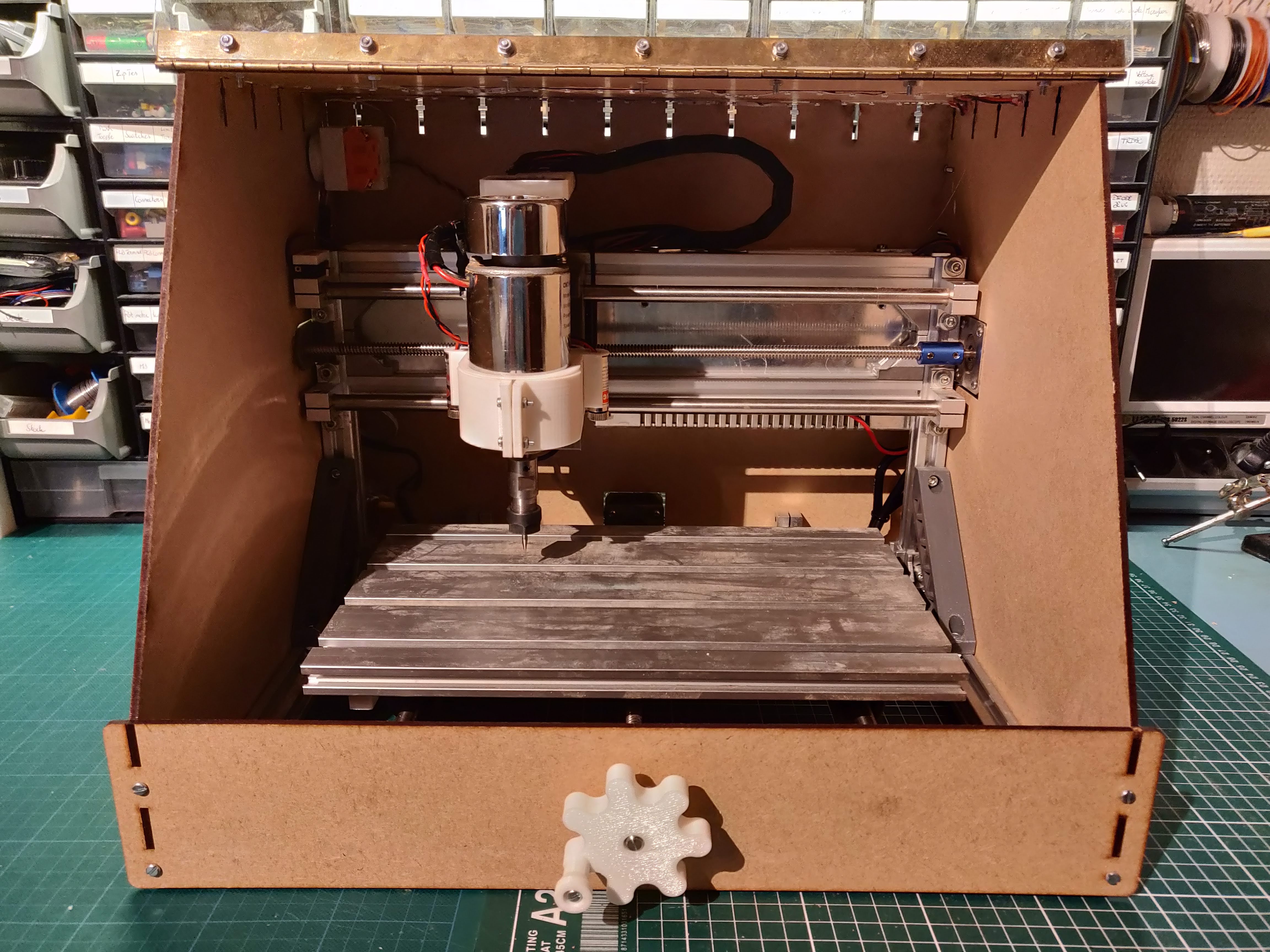
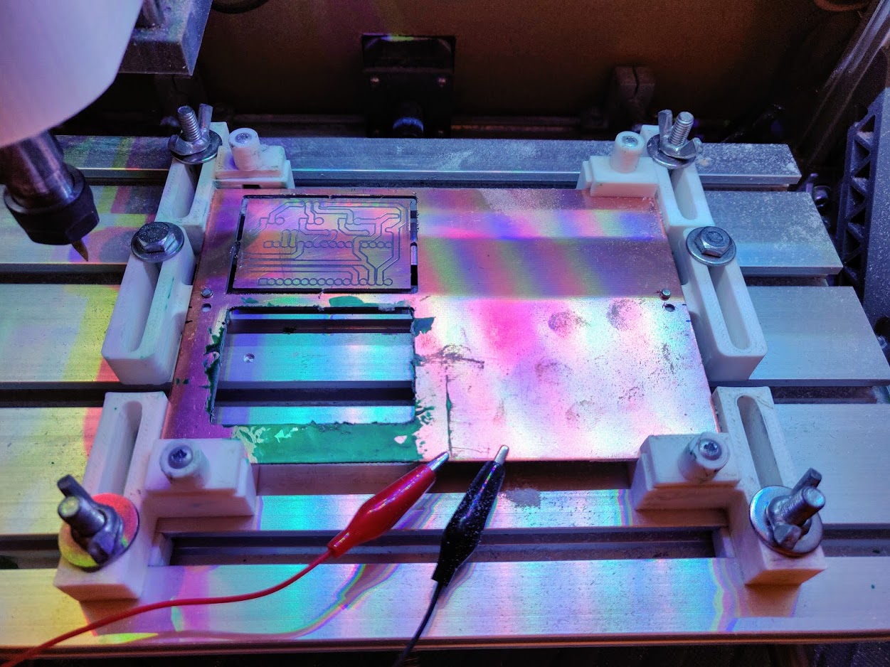
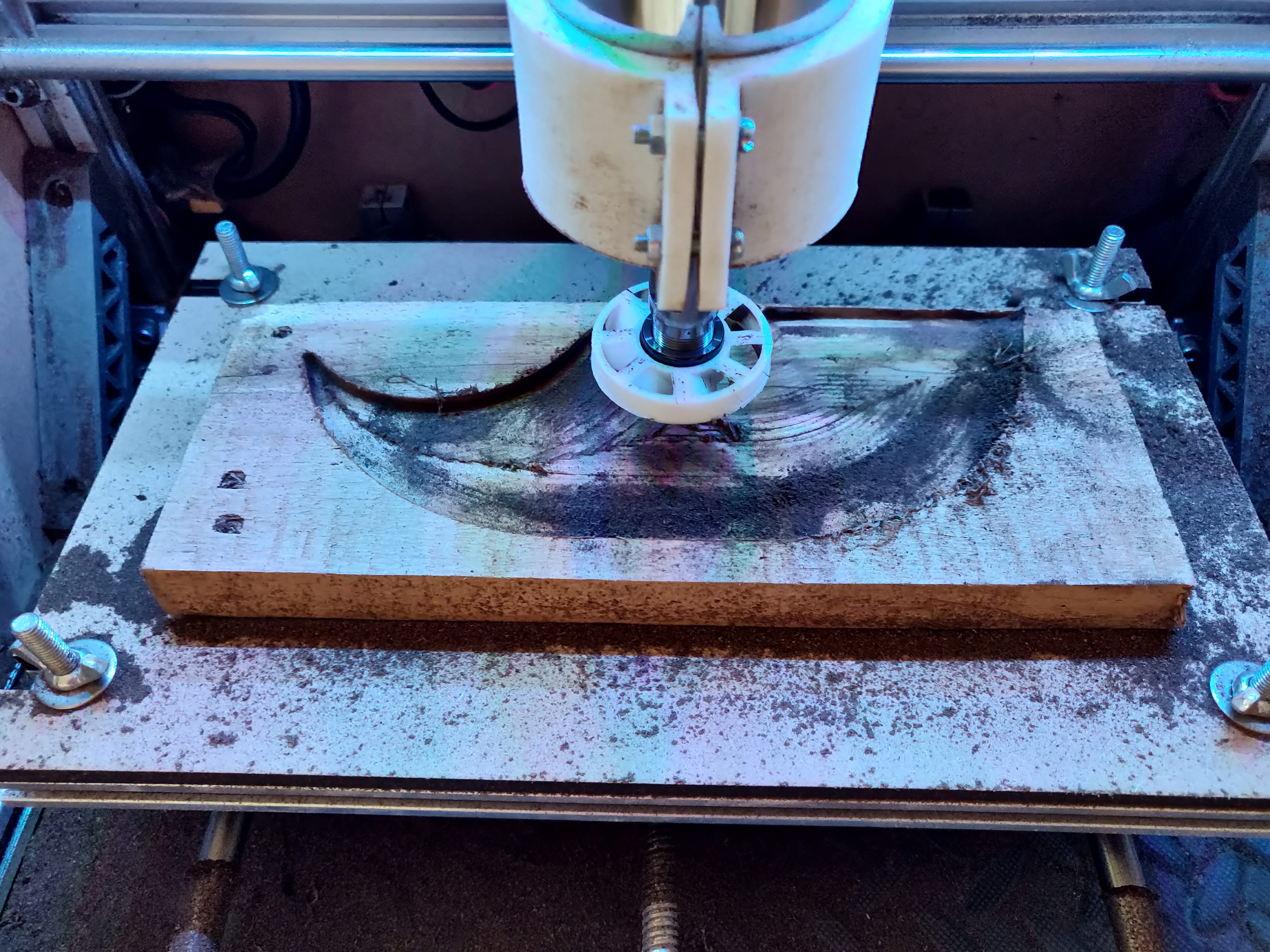
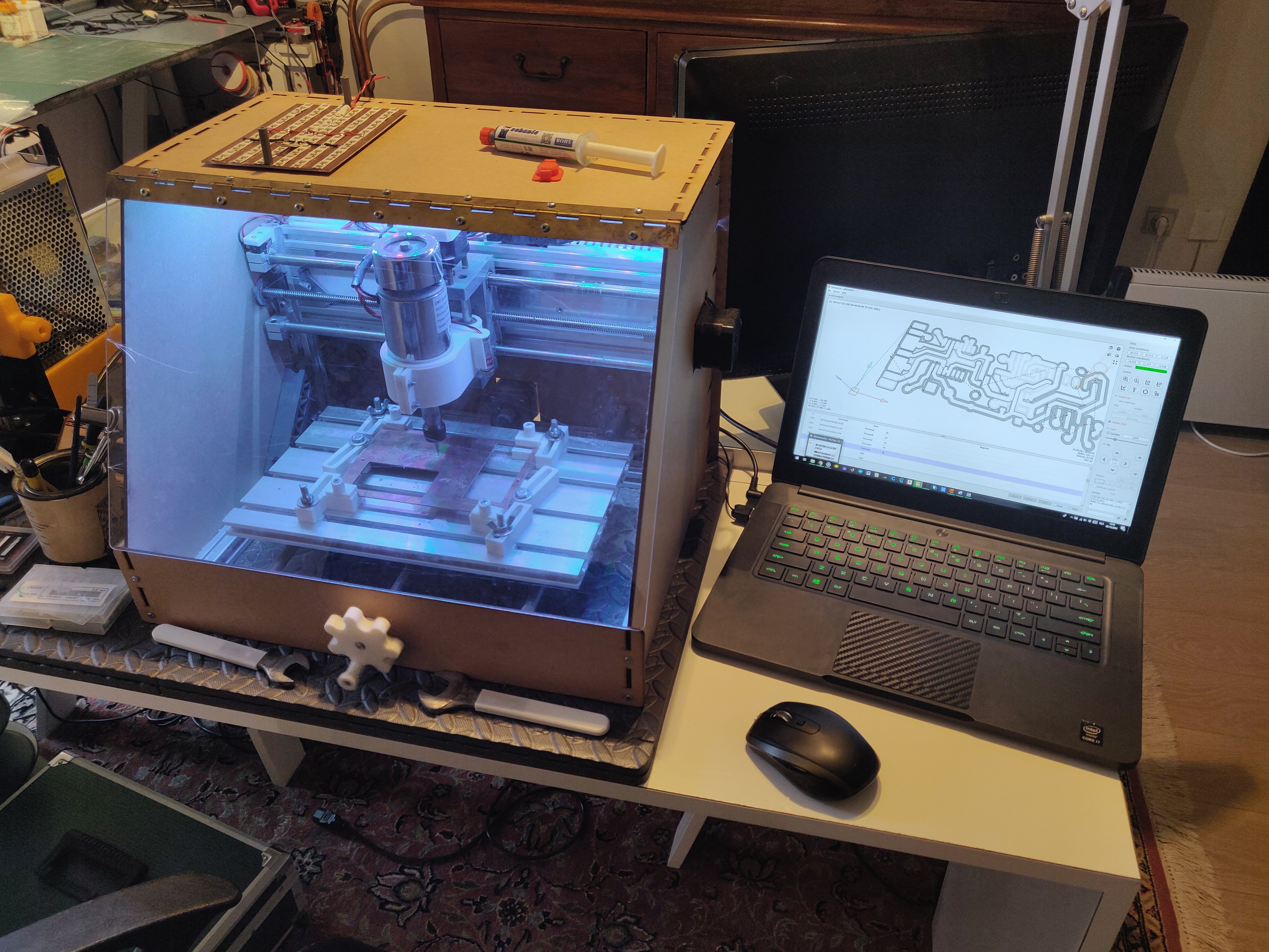
Our basic CNC kit has now been upgraded to a very capable machine, capable of milling aluminium, PCBs or anything in between. Furthermore, the case provides sound and dust isolation, which makes it perfectly usable in my office. If you have gotten inspiration to make your own, please vote for me in the Epilog contest!
I hope you liked the project! Feel free to check out my other Instructables: https://www.instructables.com/member/ThomasVDD/