Universal Arduino Remote
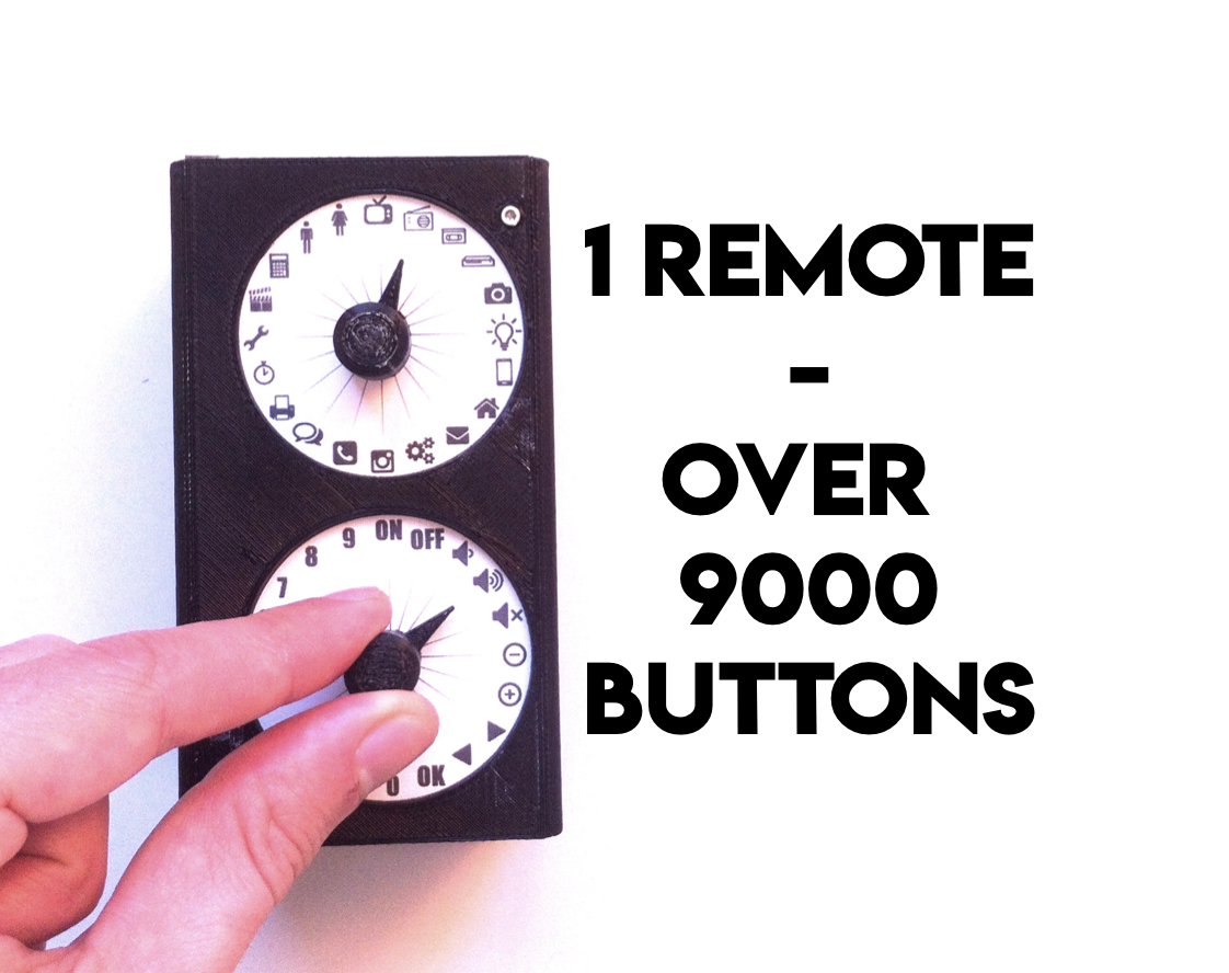
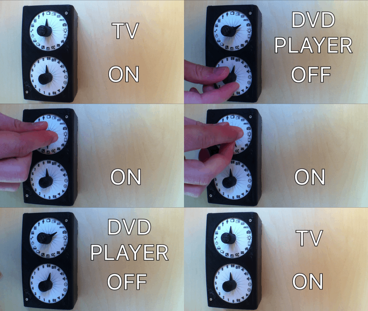
Okay, the image is a bit misleading, there are not "over 9000" buttons on this remote, but rather 400 buttons. And you can control up to 20 devices through infrared (IR), with 20 different actions.
What is it?
It is a universal remote based on an Arduino board.
Why this project?
- First, to learn more about Arduino.
- Second, because I could not find a real universal remote. I mean a remote that could control many devices. And that could be switched off, but still be ready to use (because most of the Arduino remotes I found do not save the data).
How does it work?
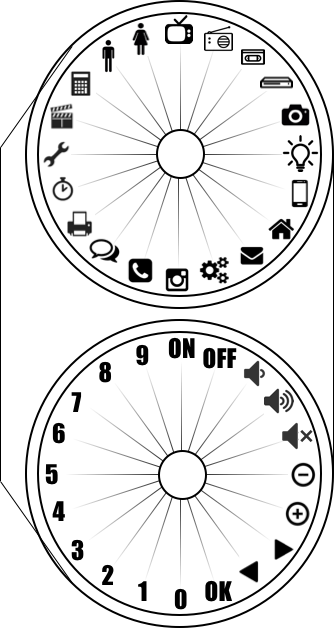
- Rotate the first knob to select the device you want to control.
- Rotate the second knob to select the action you want to do on the device.
- Long press the knob (which is also a pushbutton) to "absorb" the IR signal sent by the remote you want to clone.
- Or short press the knob to send the IR signal.
Of course, the remote has an IR receiver to "absorb" the IR signals of the remotes you want to "clone", and an IR LED to send them. These protocols are saved on a microSD card, therefore you can switch OFF the remote (and the Arduino board), it keeps the information concerning the signals on the microSD card. There are also 2 rotary encoders with 20 positions each, and that is how you can have 400 buttons. Each rotary encoder is also a pushbutton. There is a LED to inform whether the universal remote is receiving or sending IR signals. This device works on a Lithium Ion battery (18650 cell), so it is portable. And finally, there is a switch, so you can switch it ON and OFF.
What you will need:
- An Arduino board (I have used an Arduino nano for the final project because it is smaller).
- Jumper wires.
- 2 rotary encoders (I have used the KY-040).
- 1 IR receiver (I have used the KY-022).
- 1 micro SD card reader for Arduino.
- 1 micro SD card.
- 1 IR LED.
- 1 LED (any color, it does not matter).
- 1 18650 cell.
- 1 18650 cell holder.
- 1 lithium battery charger (TP4056).
- 1 boost converter (<5V to 5V).
Depending on where you buy these pieces, it can cost between few euros/dollars up to tens of euros/dollars.
Before to start:
On the first steps of this instructable, I explain how I have used each Arduino module individually. If you are already an Arduino master, you may want to go straight to the final project at step 7. If you are new to Arduino, you may want to read the first steps:
- Step 1: How to Use a LED?
- Step 2: How to Use the Micro SD Card reader?
- Step 3: How to Use the Rotary Encoder? (KY-040)
- Step 4: How to Use the Push Button? (Debounce & Short/long Press)
- Step 5: How to Use the IR Receiver? (KY-022)
- Step 6: How to Send IR Protocols?
Then come the interesting parts of the project:
- Step 7: Final Circuit (with USB Cable)
- Step 8: Final Circuit (portable, With Battery)
- Step 9: Final Device (with the 3D printed Case)
And finally, I am not a professional of Arduino boards... The final project works great, but if you find a mistake in the circuit or in the code, please let me know!
How to Use a LED?
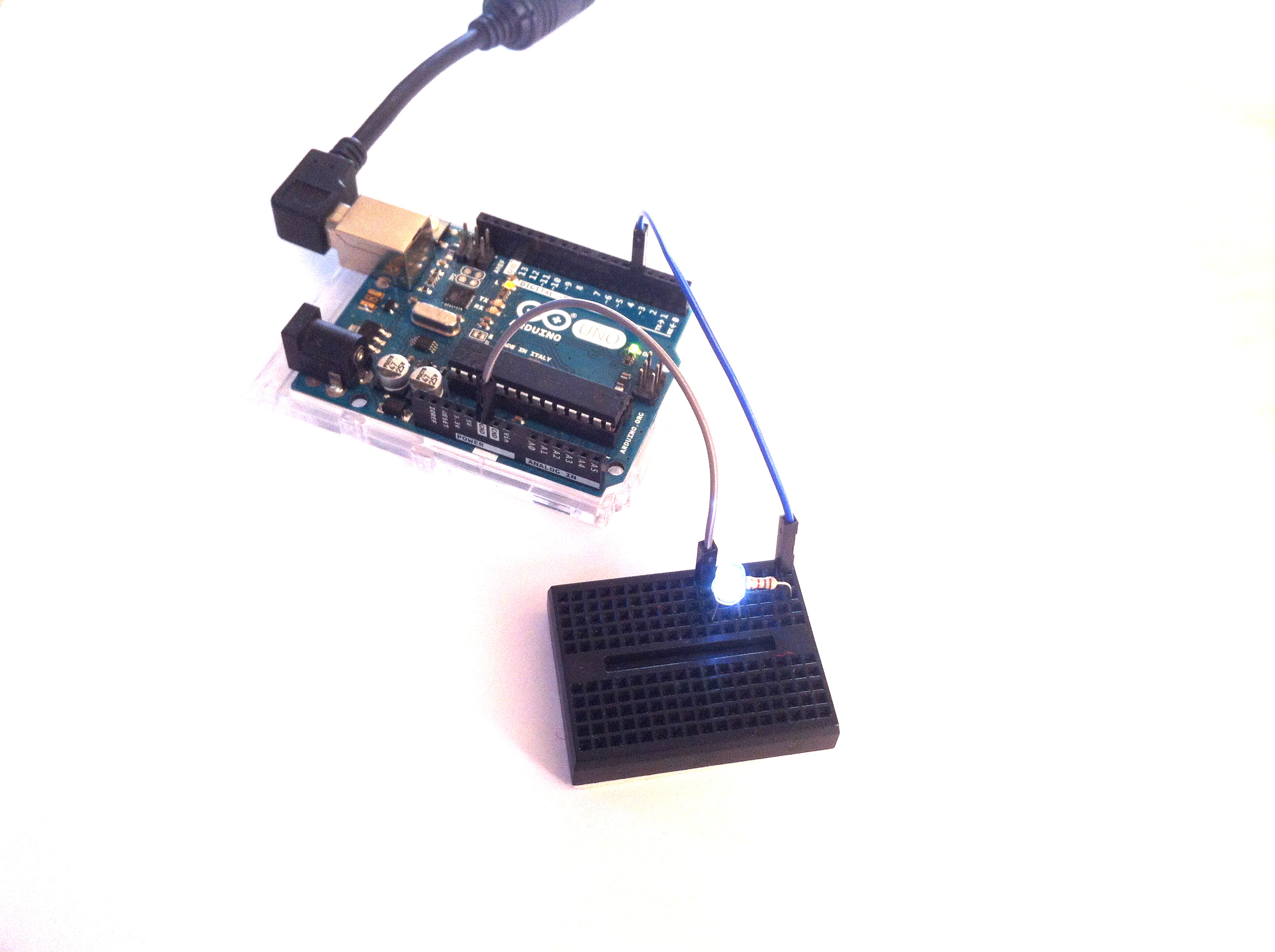
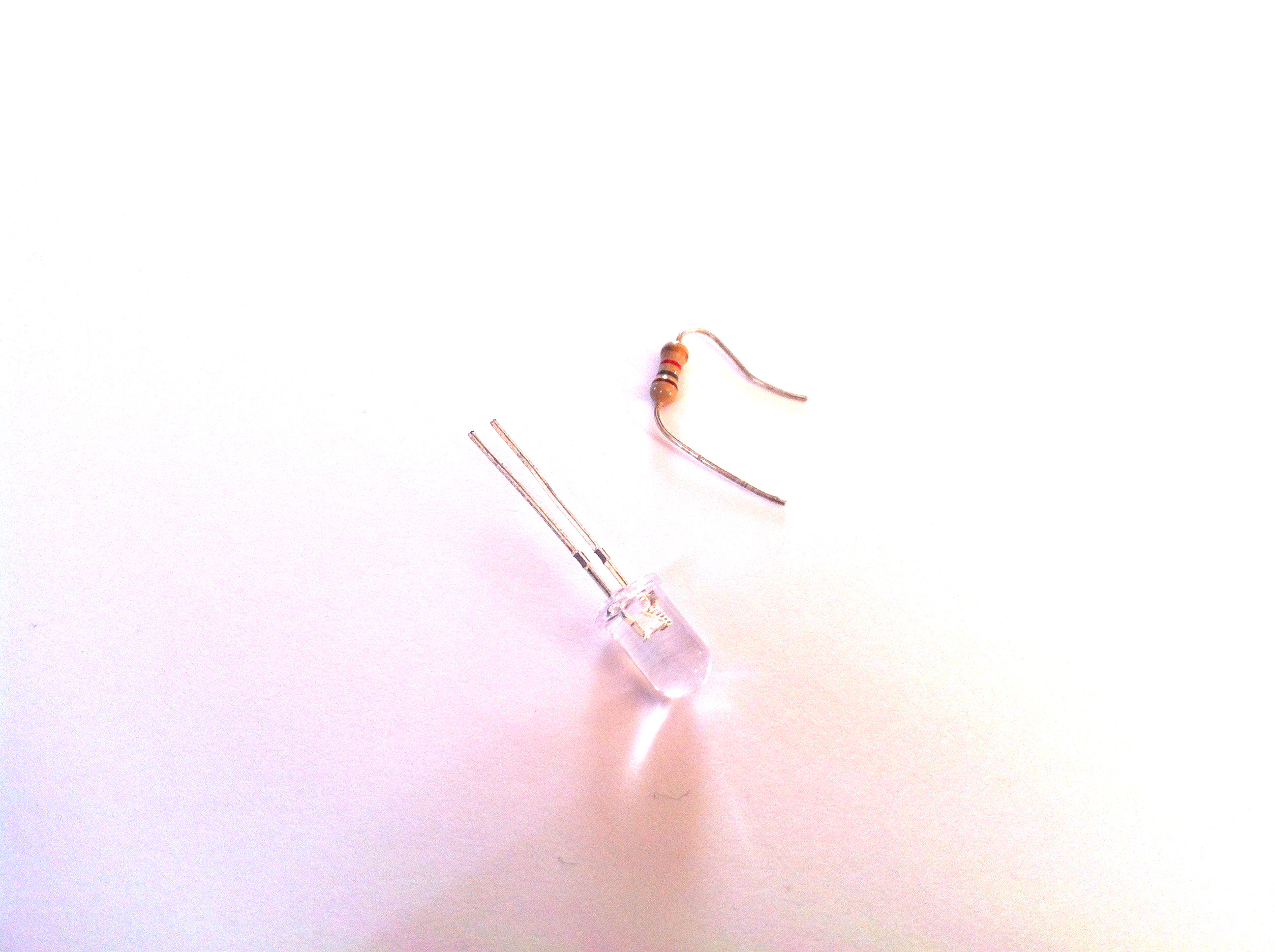
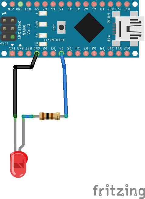
On the final project, I have added a LED to make sure the code works.
When the universal remote is ready to receive the IR signal, the LED is kept ON. Once it has been absorbed, it is kept OFF. And when the IR signal is sent from the universal remote, the LED is ON for few milliseconds. This indicates that the code is working properly.
So here you just need a LED and a resistor to protect the LED. If you have not read it yet, check the blink tutorial for Arduino. I have used a really similar code.
int LED = 4;//LED is connected to pin 4
void setup() {
  // initialize digital pin LED as an output.
  pinMode (LED, OUTPUT);
}
void loop() {
  // put your main code here, to run repeatedly:
  digitalWrite(LED, HIGH );// turn the LED on (HIGH is the voltage level)
  delay(1000);// wait for a second
  digitalWrite(LED, LOW );// turn the LED off (LOW is the voltage level)
  delay(1000);// wait for a second
}
Downloads
How to Use the Micro SD Card?
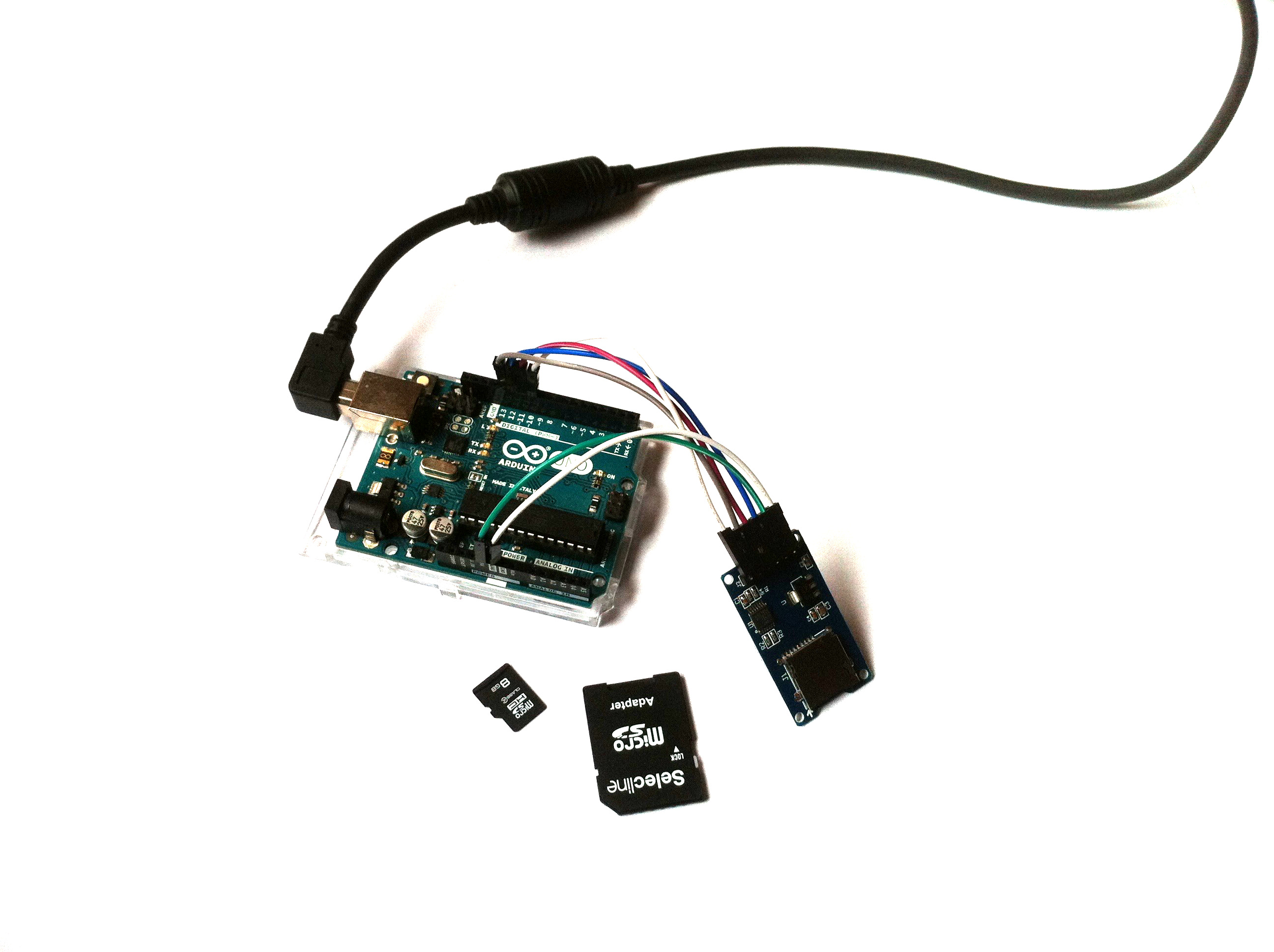
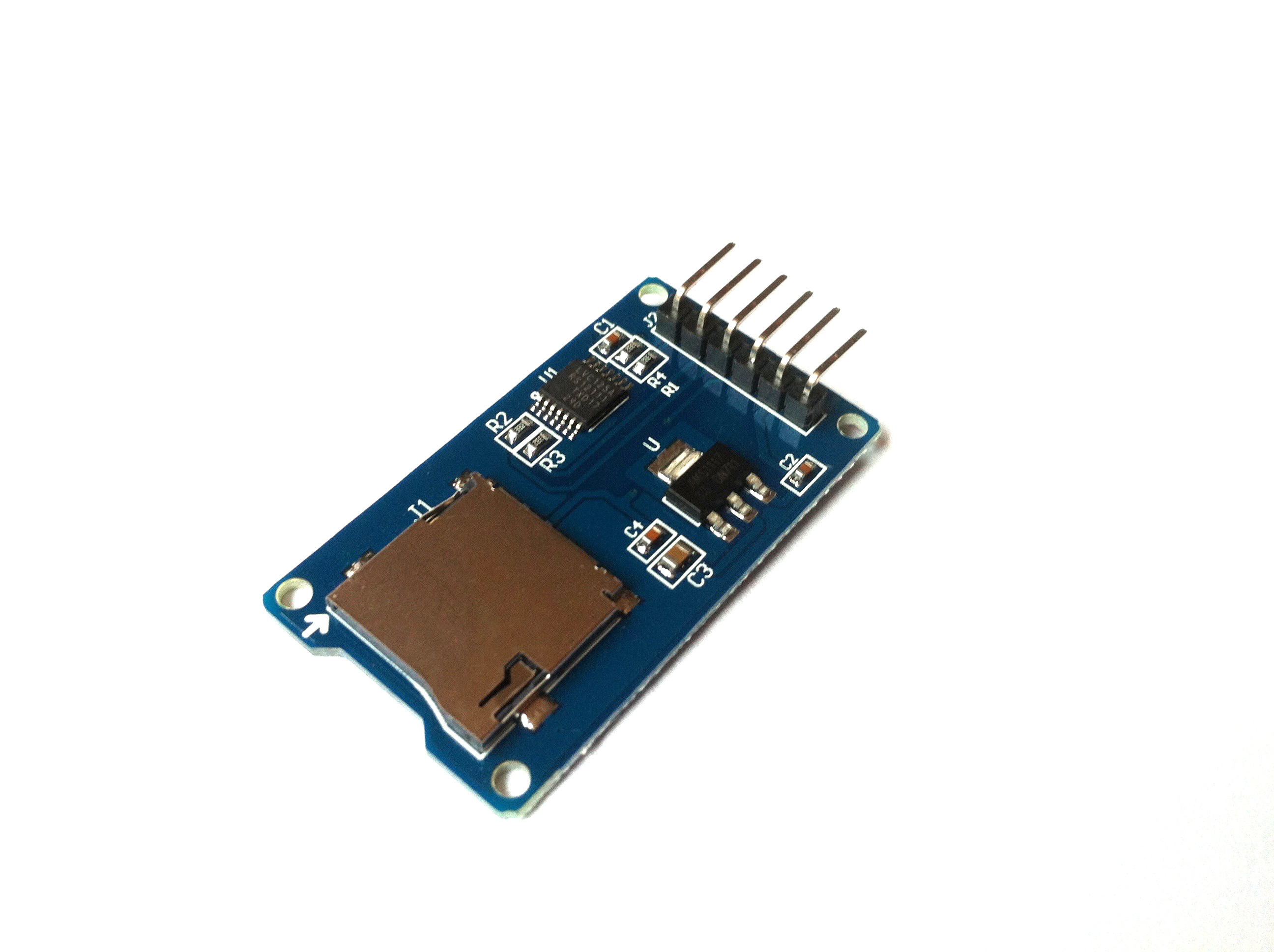
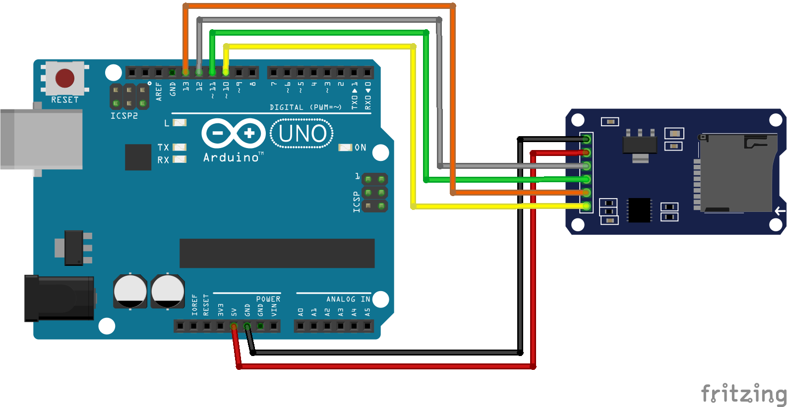
To begin with the SD card, I have started with the SD library to read/write to a file on an SD card. But I have connected the CS pin to pin 10 on the Arduino (and not on the pin 4 as shown on the previous tutorial), for more convenience (pin 10, 11, 12 and 13 are used for the SD card). This tutorial helped me understand how to save the data received from the remotes to "clone". But I needed to make it simpler, and I have added 2 features:
- Change the names of the files according to the rotary encoders values.
- Replace the information contained in one file with some other.
First thing:
In the final code, I want each information to be saved in individual ".txt" files (one IR protocol for one button). And the names of the files depend on the position of the rotary encoder.
- Example 1: Rotary encoder 1 is in position 1 (corresponding to the device n°1, for example, the TV), and rotary encoder 2 is in position 3 (corresponding to switch ON button); then I want the file to be named "1_3.txt".
- Example 2: Rotary encoder 1 on position 1 (TV), rotary encoder 2 on position 4 (volume up); file name is "1_4.txt".
- Example 3: Rotary encoder 1 in position 2 (radio), rotary encoder 2 in position 3 (switch ON); file name is "2_3.txt".
- Do you really need another example?
To do so, I have set the name of the file as a "string", and I have added in this "string" 2 "integers" (which correspond to the values of the rotary encoder). It looks like this:
int value1 = 100;
String middle = "_";
int value2 = 101;
String ext = ".txt";
String SDname;
SDname = value1 + middle + value2 + ext;
Second thing:
In the final code, I want each IR protocol saved to be changed if wanted. Imagine you save the wrong protocol, you may want to resave it, with the right value.
So first I have tried to remove the text in the files using the function "SD.remove()". It worked great with the small code with just the SD card, but unfortunately, it did not work for the final code with all the modules (step 7)... And I have no idea why.
So the easiest function that I found to replace "SD.remove()" was the FileSeek function which seeks to a new position in the file. So in my code, I go to position 0, and I add some text. This way, the file is not renewed, but the first lines are replaced, and that is enough for me. Here is the interesting line:
myFile.seek(0);
Finally, you can download the code I have made to play with the SD card. To summarize, in this code I wanted to make the following:
- Create a text file named according to int values of the rotary encoders (value1 and value2).
- Write 3 lines on this file.
- Close this file, reopen it and replace the 3 first lines.
- Then make a loop of the previous steps increasing the values in the text file name.
Downloads
How to Use the Rotary Encoder? (KY-040)
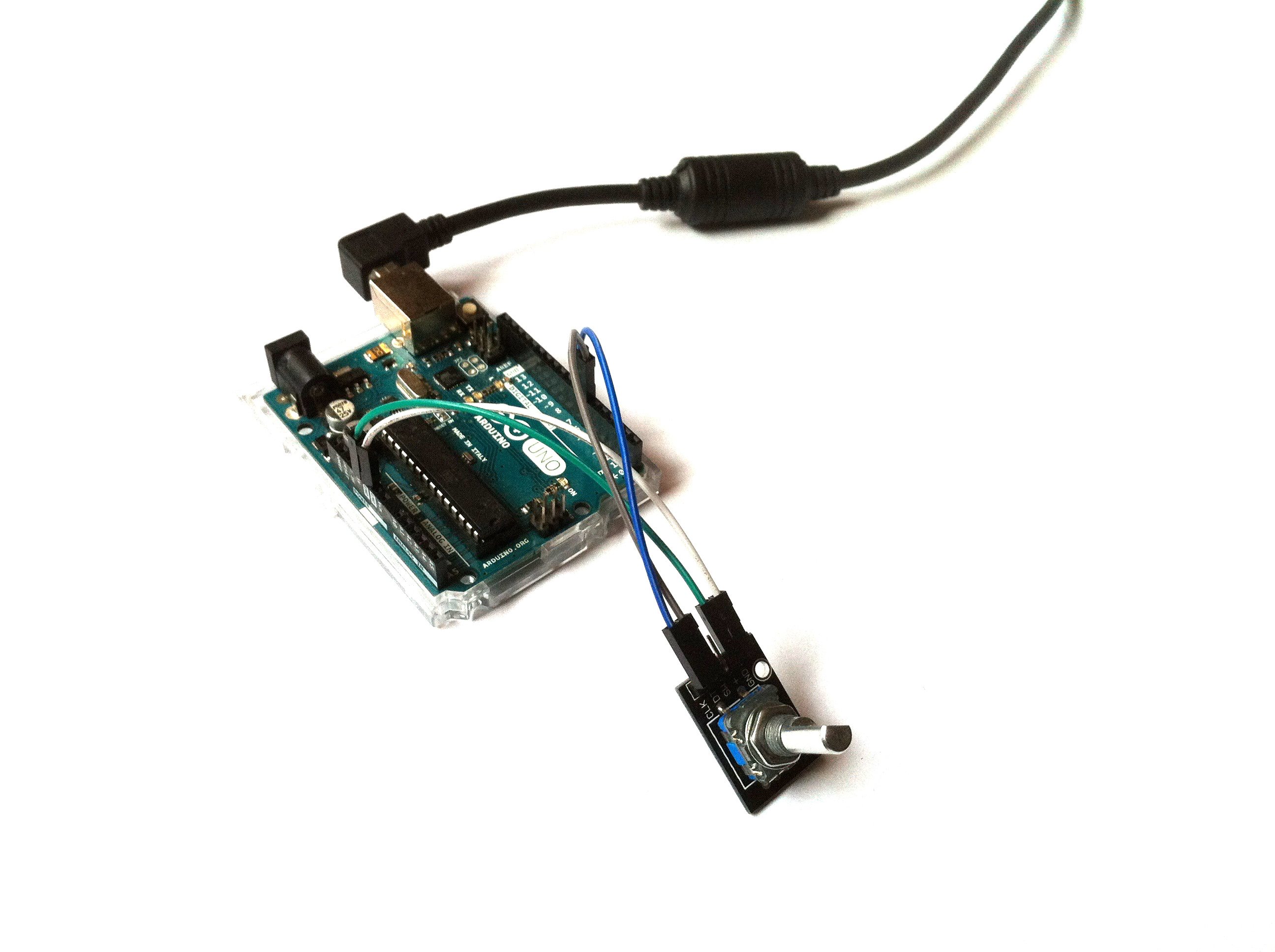
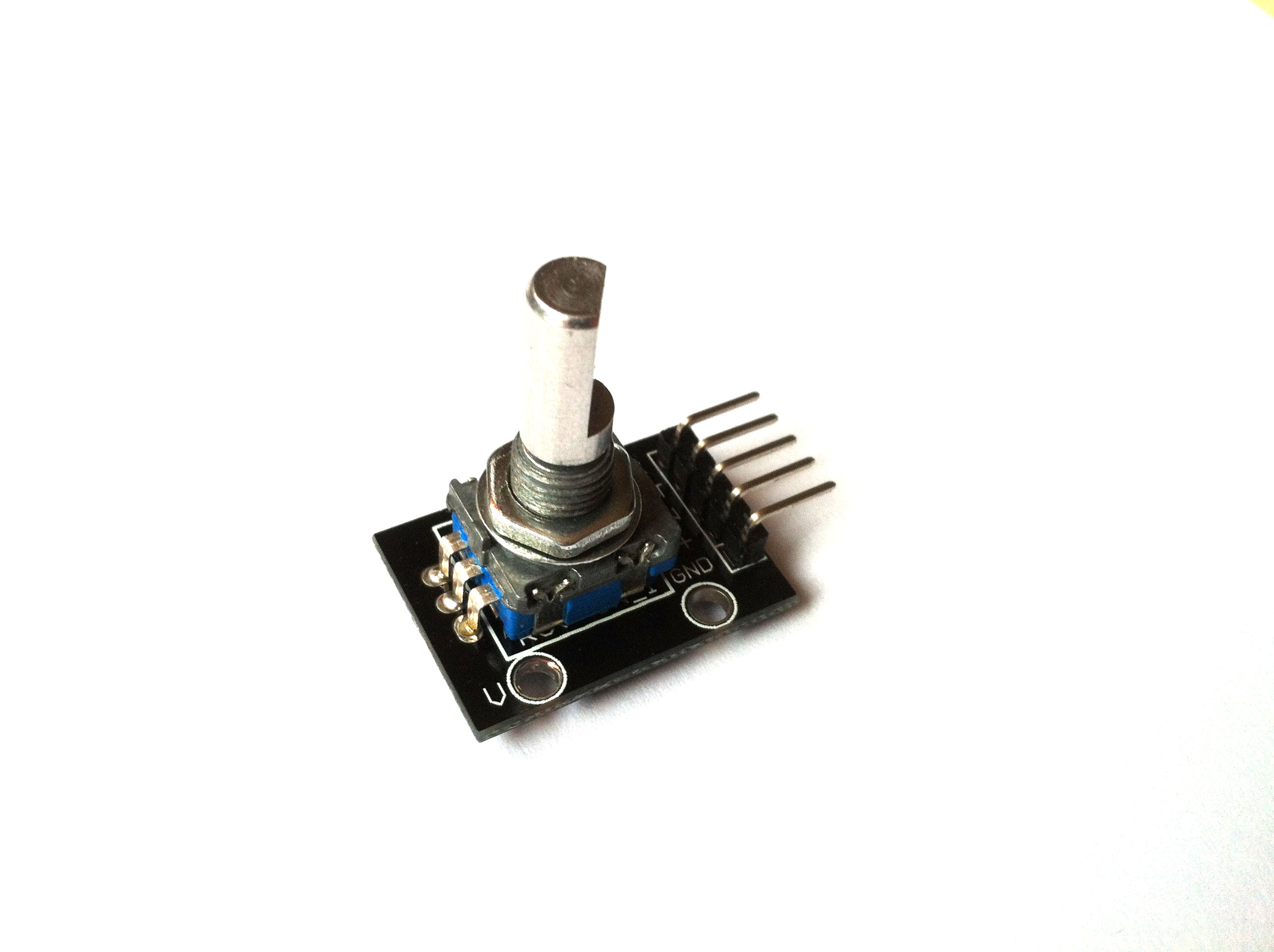
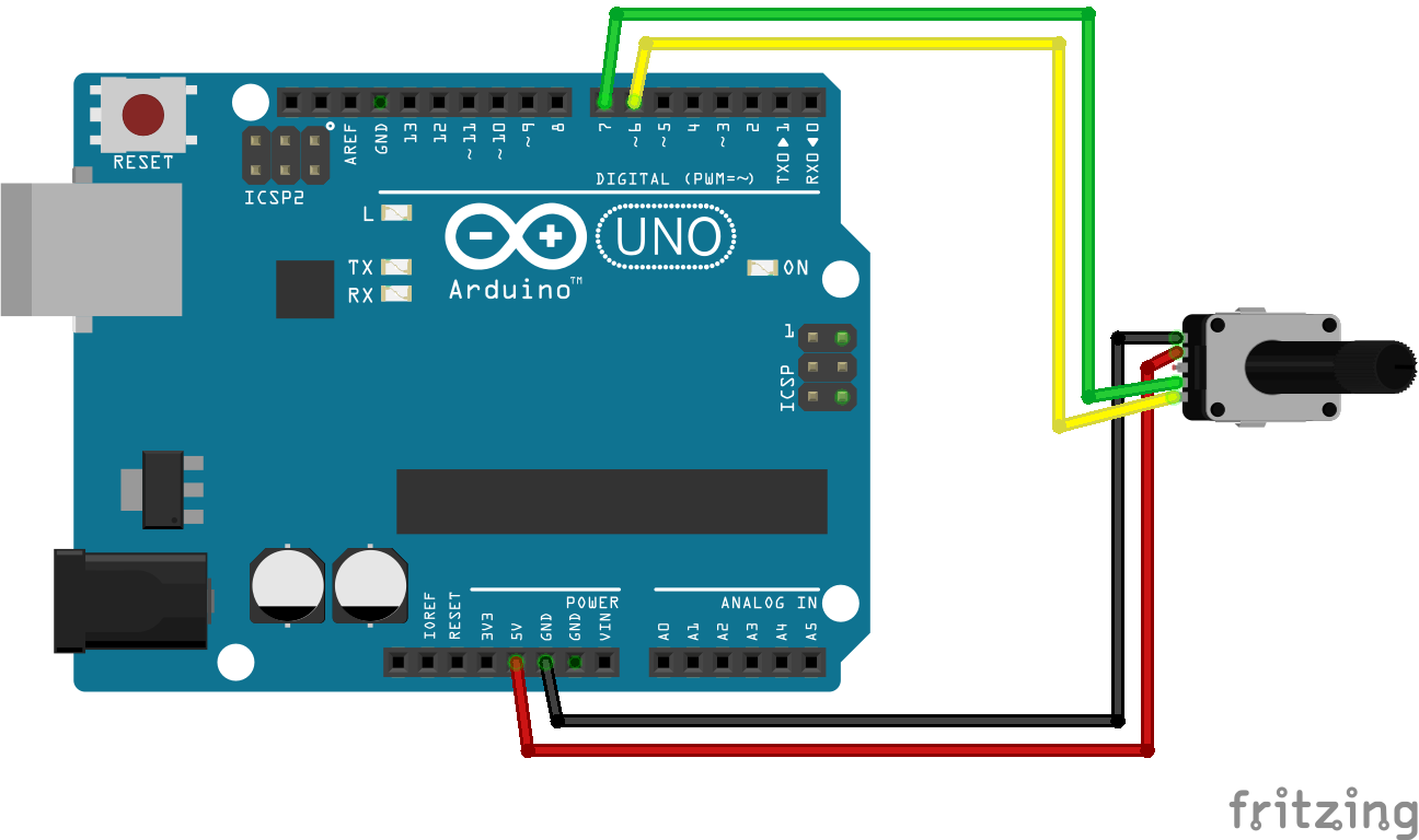
Concerning the rotary encoders, I have learned how to use them with this tutorial: How Rotary Encoder Works and How To Use It with Arduino.
The encoders are really important in the universal remote because it is possible to reach 400 buttons, with the combination of the 20 positions on each encoder! And if you want to add a third rotary encoder, you could have 8000 buttons! Or just 2 encoders with 40 positions would give 1600 buttons! But to my point of view, 400 buttons is way enough to control every IR controlled device you have ever seen.
I made 2 mains changes on the code provided by the tutorial:
- First, on the previous reference, each step of the encoder has a value of 2. So 0, 2, 4, 6... So I have multiplied this value by 0.5 to obtain a step with a value of 1: 0, 1, 2, 3, 4...
- Second, I want the value of the rotary encoder to be kept between 0 and 19 (20 positions). On the code that you can try in the previous reference, the values which are saved on the "counter" variable keep increasing even after 19. Example: after 1 rotation of the rotary encoder, the value of "counter" is 21. And it continues like this 21, 22, 23. After 2 rotations of the encoder, the value is 41. And so on. And similarly, there are negative values for "counter" if you turn the encoder counterclockwise. And I want on my code that the value of the encoder goes back to 0 after any full rotation. If you keep rotating the encoder in the clockwise direction, it would give: 0, 1, 2, 3, 4, 5 ,6, 7, 8, 9, 10, 11, 12, 13, 14, 15, 16, 17, 18, 19, 20, 0, 1, 2, 3, 4, 5 ,6, 7, 8, 9, 10, 11, 12, 13, 14, 15, 16, 17, 18, 19, 20, 0, 1, 2, 3, 4, 5 ,6, 7, 8, 9, 10, 11, 12, 13, 14, 15, 16, 17, 18, 19, 20... To fix this issue, I have used a modulo operator of 40 (before to multiply by 0.5).
Anyway, this is easily made with the following line of code:
val1 = (counter % 40) * 0.5;
With "val1" an integer variable I have created to replace the variable "counter".
And this is the code I made for 1 rotary encoder. In the final code of the remote, I have added a second rotary encoder, so I just created the same variables with different names.
#define outputA 6 //CLK
#define outputB 7 //DT
int counter = 0;
int aState;
int aLastState;
int val1;
void setup() {
  pinMode (outputA, INPUT);
  pinMode (outputB, INPUT);
  Serial.begin (9600);
  // Reads the initial state of the outputA
  aLastState = digitalRead(outputA);
}
void loop() {
  aState = digitalRead(outputA); // Reads the "current" state of the outputA
  // If the previous and the current state of the outputA are different, that means a Pulse has occured
  if (aState != aLastState) {
    // If the outputB state is different to the outputA state, that means the encoder is rotating clockwise
    if (digitalRead(outputB) != aState) {
      counter ++;
    } else {
      counter --;
    }
    Serial.println(counter);
    val1 = (counter % 40) * 0.5;
    Serial.print("Position: ");
    Serial.println(val1);
  }
  aLastState = aState; // Updates the previous state of the outputA with the current state
<br>
Downloads
How to Use the Push Button? (Debounce & Short/long Press)
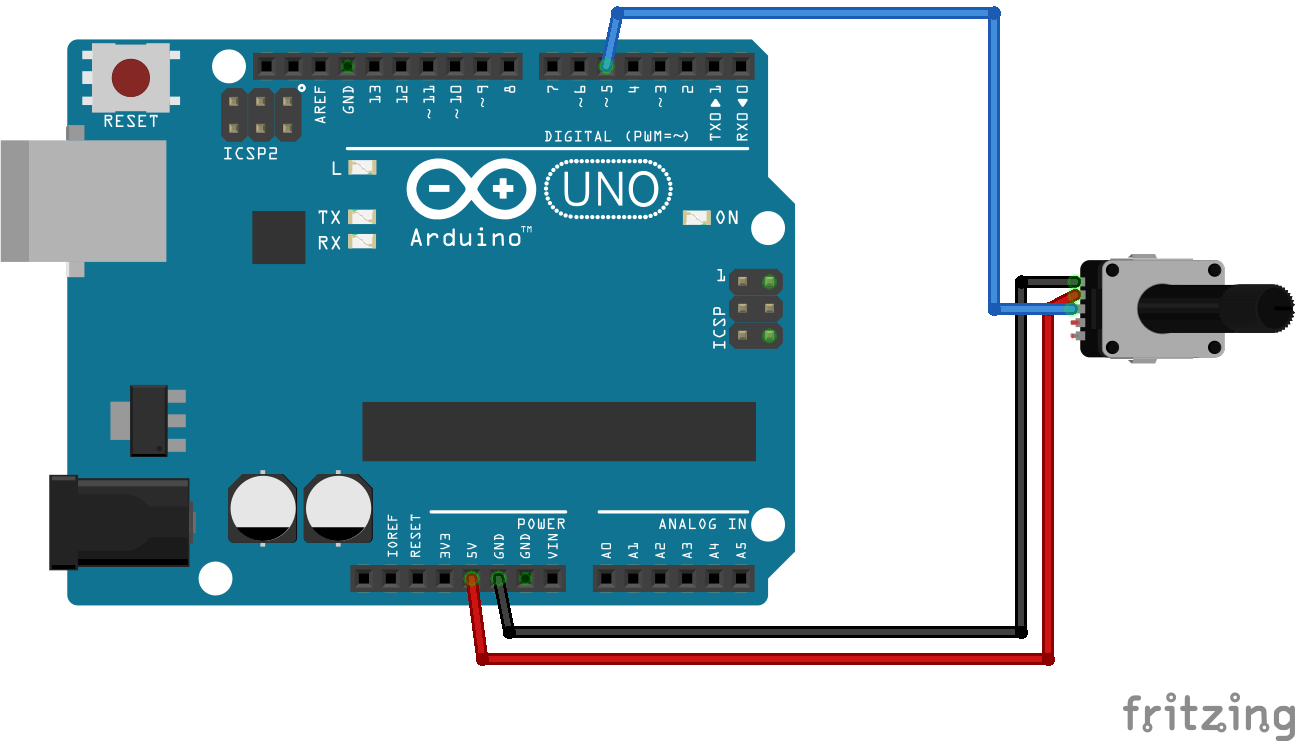
In this step, I use the same module as in the previous step, the KY-040, because it has a push button when you press the module.
In my final remote I want a press button for 2 main reasons:
- A long press to launch the "absorption" of the signal by the universal remote.
- A short press to send the IR signal.
To do so, I have used the bounce library . And then I have proceeded as follow:
To make a long press:
For the long press, the code enters a "while" loop while the press button is pressed. In this loop, there is a counter which increases for each loop. And if this counter exceeds a threshold, then the action is done. In the following example, the message "Long press" is displayed.
while ( value == LOW ) {
	debouncer.update();
    value = debouncer.read();
    debouncer.update();
    delay(5);
    if (counter > 100) {
      Serial.println("Long press!");
      delay(1000);
      counter = 0;
    }
    counter++;
  }
To make a short press:
I have added another loop, an "if" loop, in which the code enters if the counter that has been launched by the "while" loop previously is above a threshold (I have empirically chosen a value of 5 here).
if (counter > 5) {
Serial.println("Short press!");
delay(1000);
}
And here is the final code:
#include <Bounce2.h><br>#define BUTTON_PIN 5
int counter = 0;
Bounce debouncer = Bounce();
void setup() {
  Serial.begin(9660);
  // Setup the button with an internal pull-up :
  pinMode(BUTTON_PIN, INPUT_PULLUP);
  // After setting up the button, setup the Bounce instance :
  debouncer.attach(BUTTON_PIN);
  debouncer.interval(5); // interval in ms
}
void loop() {
  // Update the Bounce instance :
  debouncer.update();
  // Get the updated value :
  int value = debouncer.read();
  while ( value == LOW ) {
    debouncer.update();
    value = debouncer.read();
    debouncer.update();
    delay(5);
    if (counter > 100) {
      Serial.println("Long press!");
      delay(1000);
      counter = 0;
    }
    counter++;
  }
  if (counter > 5) {
    Serial.println("Short press!");
    delay(1000);
  }
  counter = 0;
}
Downloads
How to Use the IR Receiver? (KY-022)
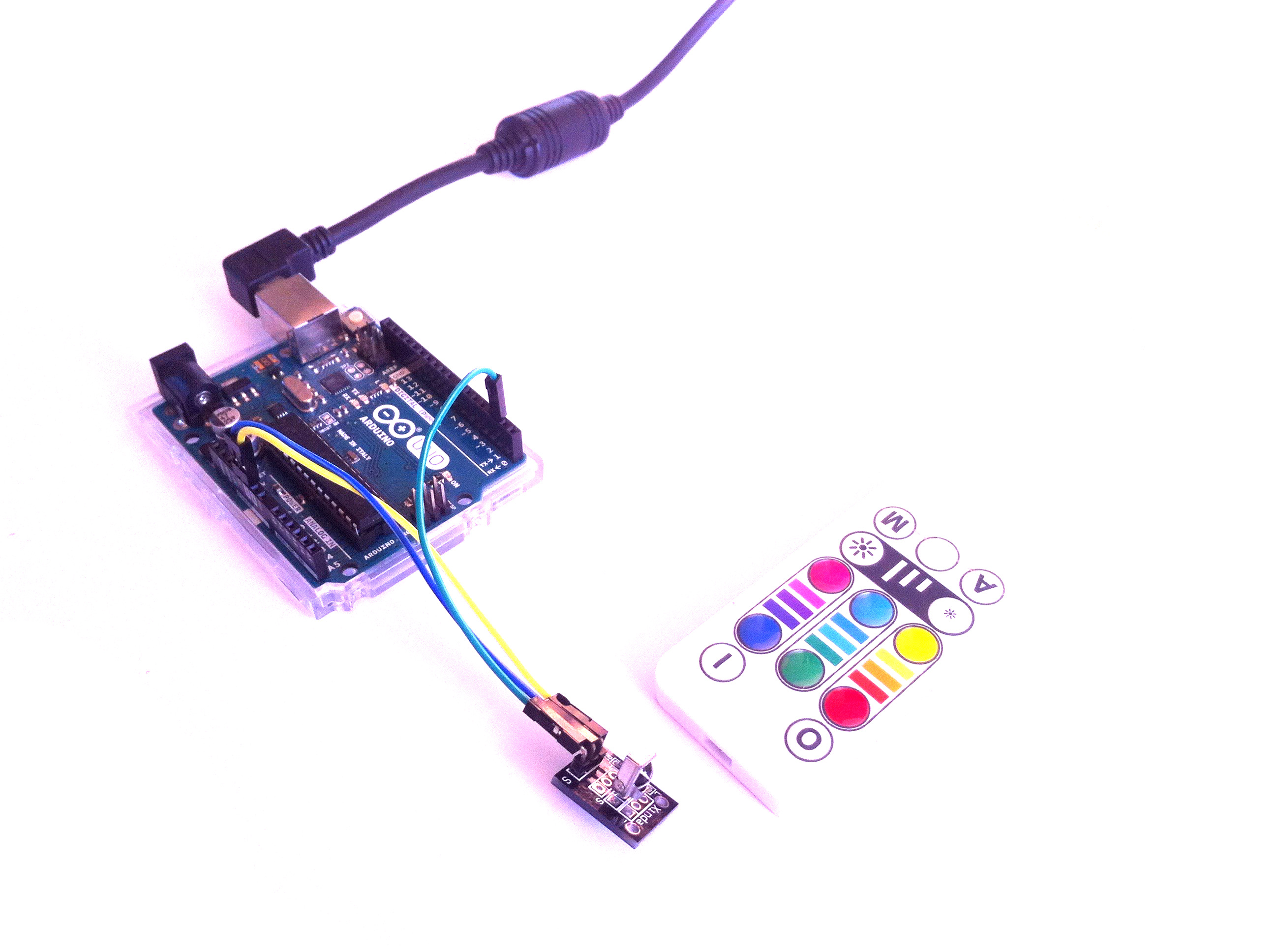
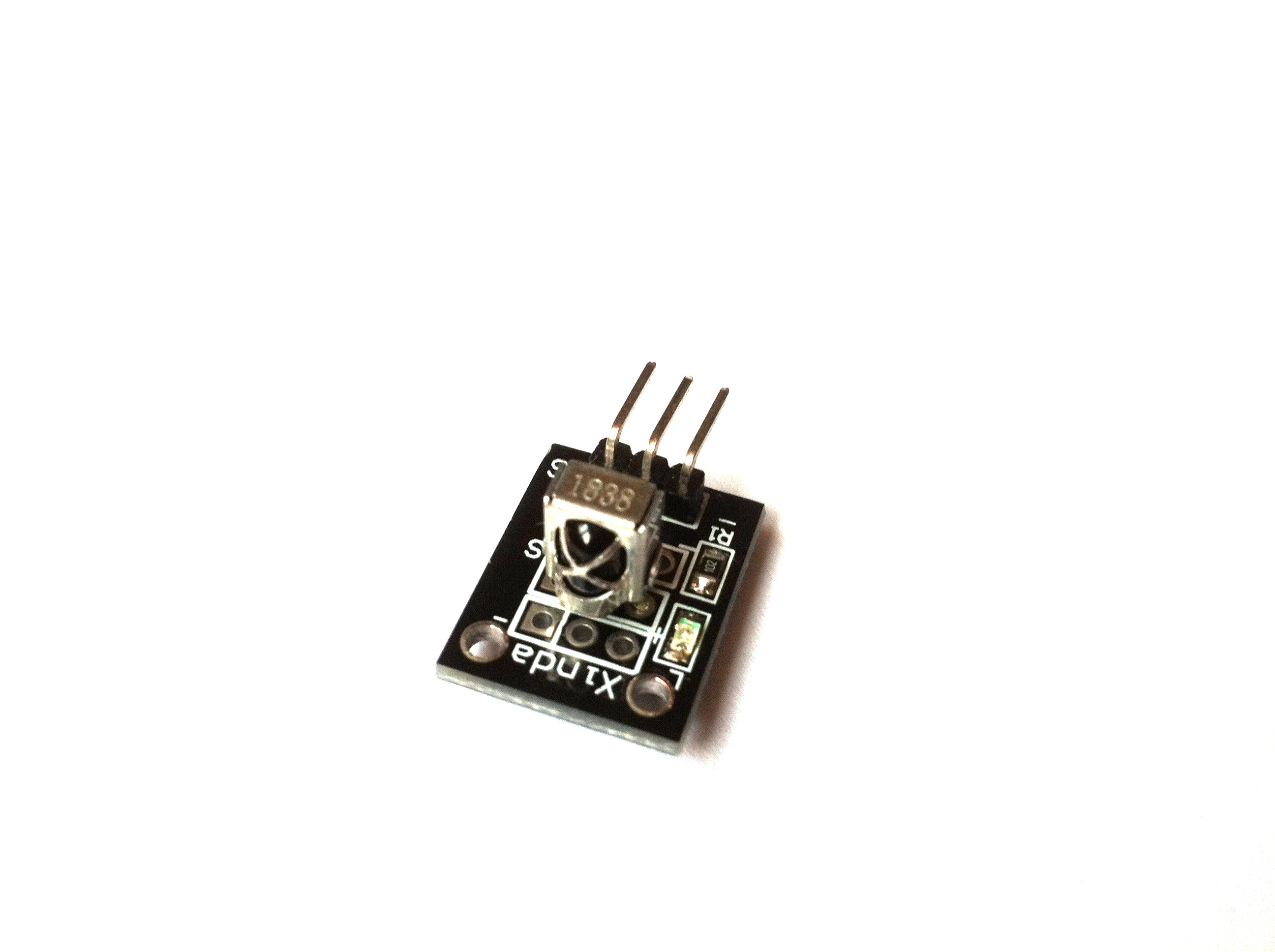
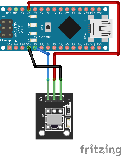
To absorb the IR signals, I have used an IR receiver, KY-022. For this step and the next one, I have used a tutorial found on adafruit: Using an Infrared Library on Arduino .
And I have used the example called "comboDump.ino" in the IRLib2. With this example, you can select the protocols you want to use, instead of the full library.
I found here that I can obtain the protocol number (by using myDecoder.protocolNum), the number of bits (myDecoder.bits), and the decoded data value (myDecoder.value). This is important because I need those 3 data to send the IR in the next step. So I have decided to display them in my code:
Serial.println(myDecoder.protocolNum);
Serial.println(myDecoder.bits);
Serial.println(myDecoder.value);
And you can download the final code with the file I have added.
Downloads
How to Send IR Protocols?
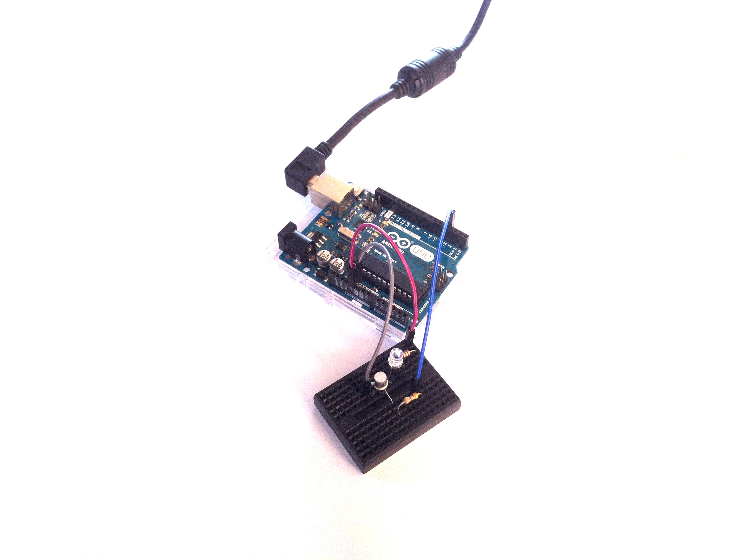
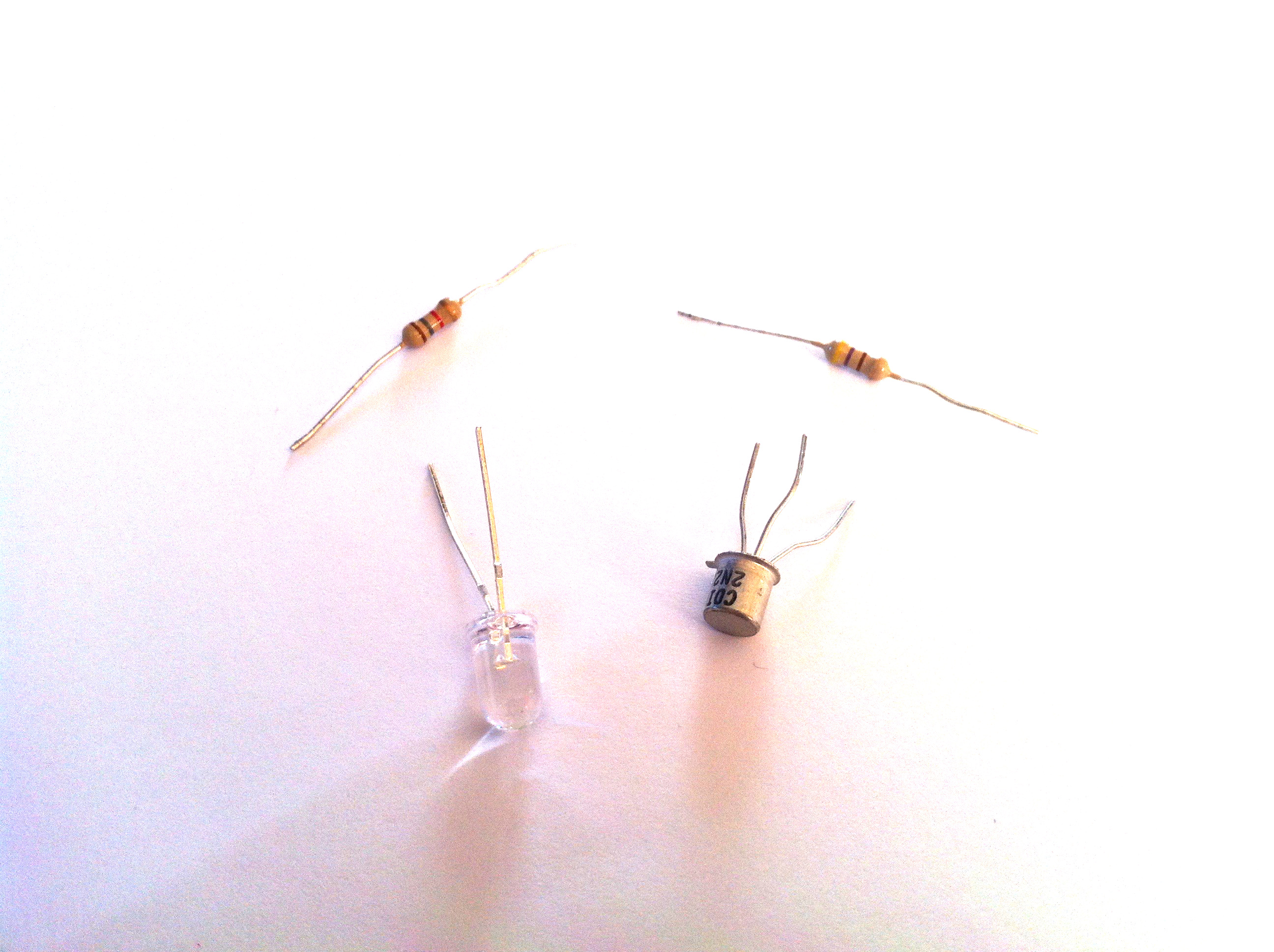
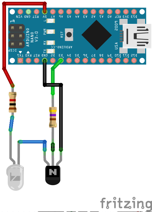
To send the IR signal, I have followed the next part of the adafruit tutorial. I have used the same circuit and the same code.
But have made some small changes:
I have used the protocol number, the number of bits and value sent recorded from the previous step. And I have used them, just like this:
mySender.send(Protocol, Data, Bits);
To do so, I have created 3 "strings" containing the previous data. And I change these strings into integers. Now you might wonder why I create "strings" before the "integers"? And not directly the integers? It is related to the full code, and I will explain this in the next step.
Because the IR LED is invisible, you can change it with a regular colored LED, and you will see how it blinks. Or you can observe the IR light through a camera.
And the final code is the following:
#include <IRLibAll.h>
IRsend mySender;
void setup() {
  Serial.begin(9600);
}
void loop() {
  String line1 = "1";
  String line2 = "32";
  String line3 = "33454215";
  //mySender.send(1,33454215, 32);
  mySender.send(line1.toInt(), line3.toInt(), line2.toInt());
  delay(1000);
}
Downloads
Final Circuit (with USB Cable)
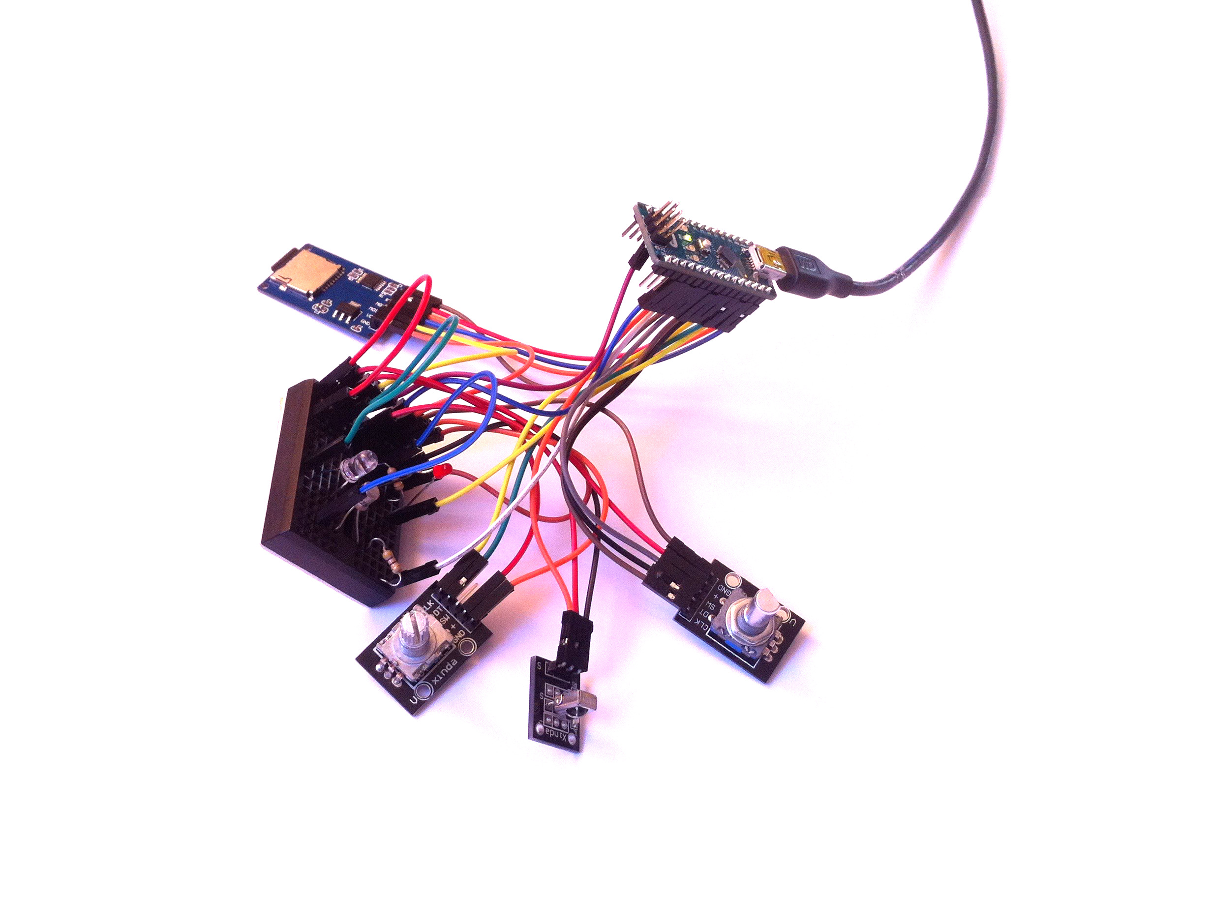
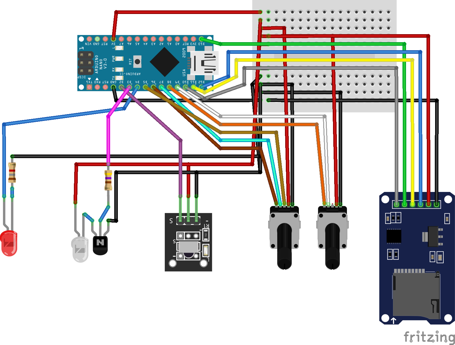
And here is the final circuit with the final code! The circuit contains all the electronic parts I have written about in the previous steps (on the same pins as described) and the same parts of the code.
But there are some small differences:
- To connect each module to 5V and ground, I have used a breadboard.
- There are 2 rotary encoders. As explained previously, I have used the same code, but creating some new variables for the second rotary encoder.
- Some variables had similar names, so I renamed them.
- To read the data to send(which have been saved in the text file on the SD card), I have used the function file.readStringUntil(). I want the information on each line, so I have used file.readStringUntil('\n'), which means: read the line until the next one. This is what you can see in the following part of the code:
while (myFile1.available()) {
digitalWrite(LED_PIN, HIGH );
        delay(100);
        String line1;
        String line2;
        String line3;
        int One;
        int Two;
        long Three;
        if (it == 1) {
          line1 = myFile1.readStringUntil('\n');
          One = line1.toInt();
        }
        if (it == 2) {
          line2 = myFile1.readStringUntil('\n');
          Two = line2.toInt();
        }
        if (it == 3) {
          line3 = myFile1.readStringUntil('\n');
          Three = line3.toInt();
          mySender.send(One, Three, Two);
          myFile1.close();
        }
        it++;
      }
Downloads
Final Circuit (portable, With Battery)
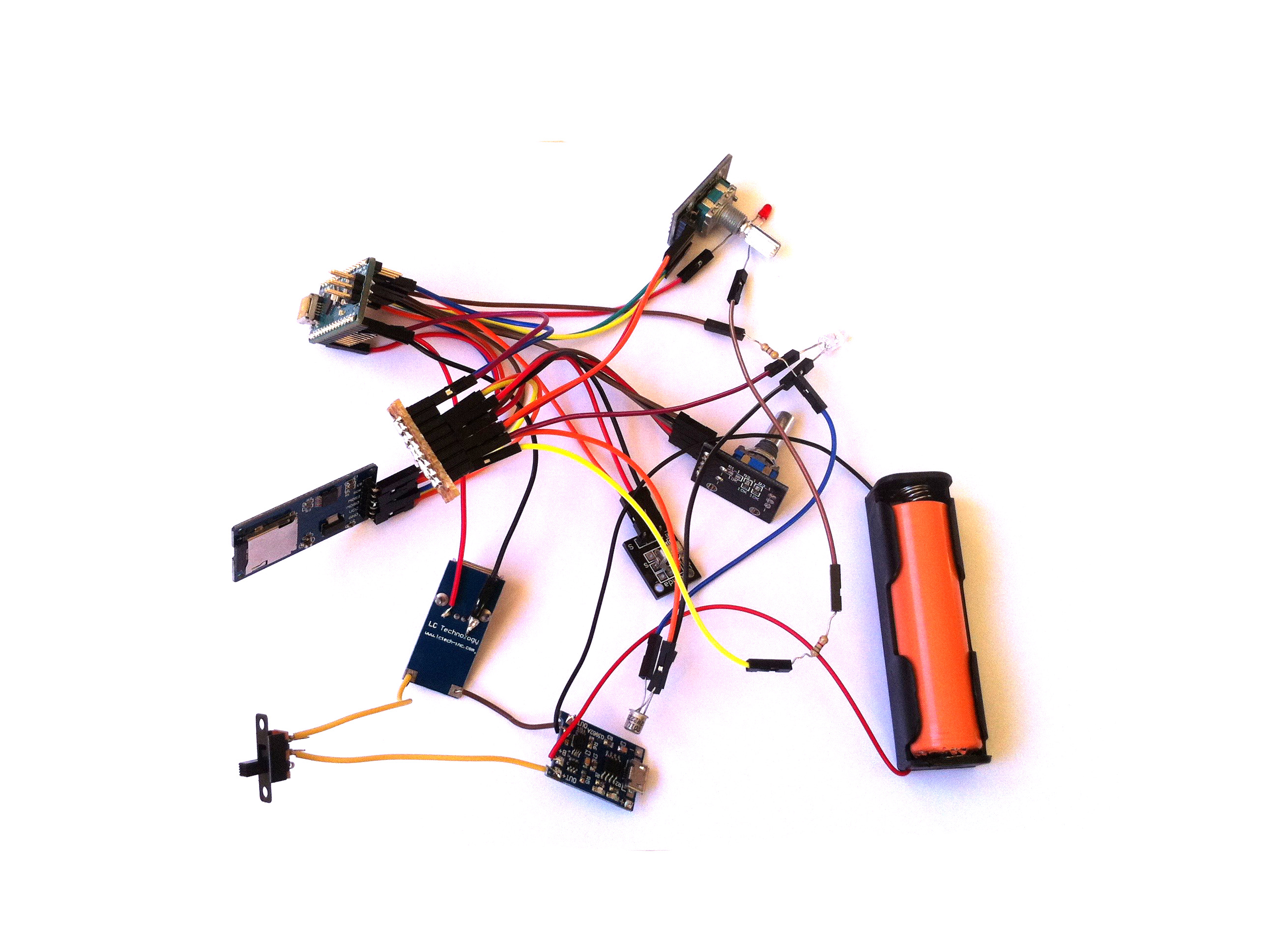
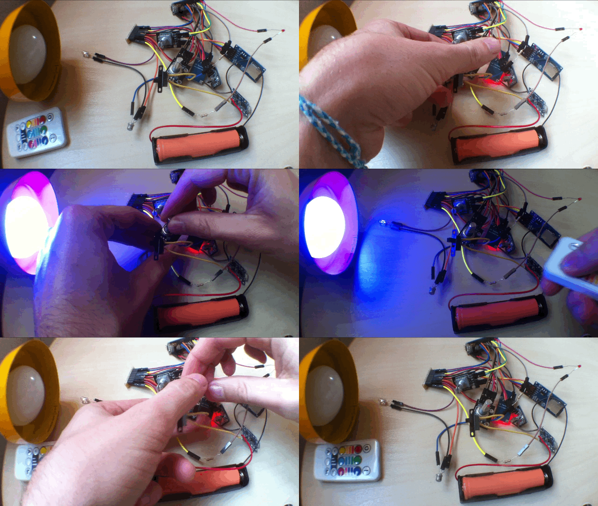
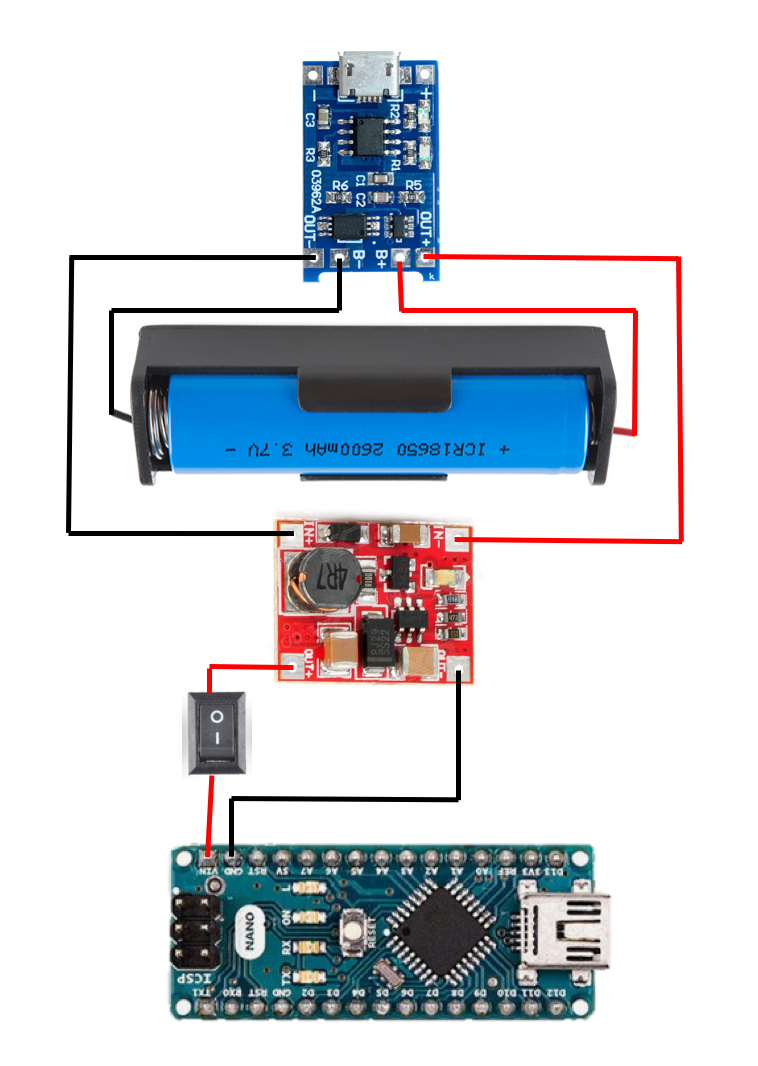
Finally, I wanted to make this remote portable, so I have added a battery (18650 cell and the cell holder), something to charge it (a TP4056 module), a boost converter to provide energy to the Arduino board from the battery, and a switch.
Unfortunately, the boost converter I have used is not really suitable because it has a USB plug...
And I have also replaced the breadboard with some kind of hubs, soldering the 5V wires together, and the ground wires together.
Final Device (with the 3D Printed Case)
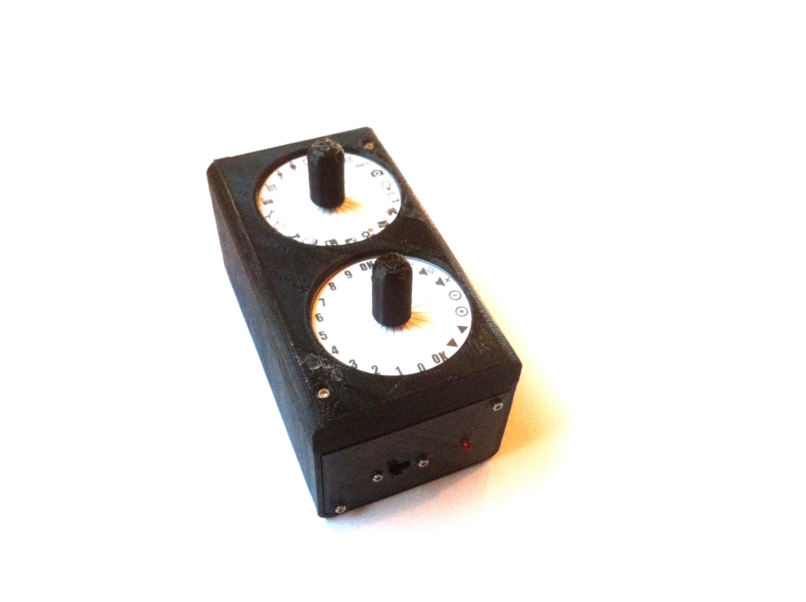
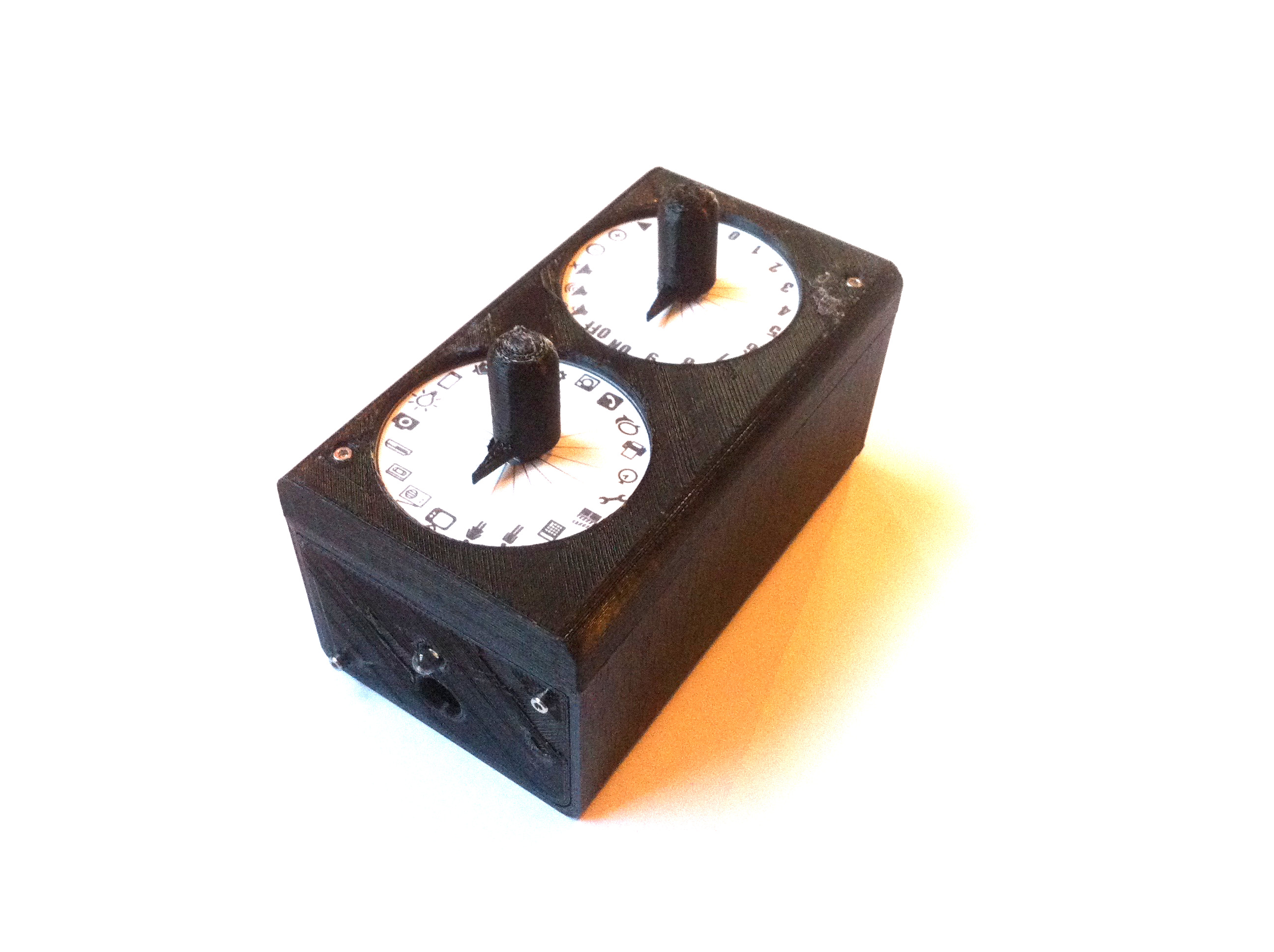
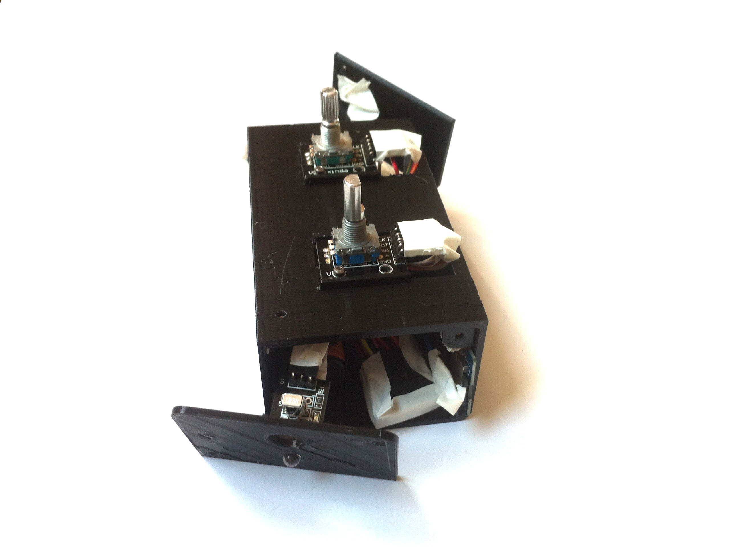
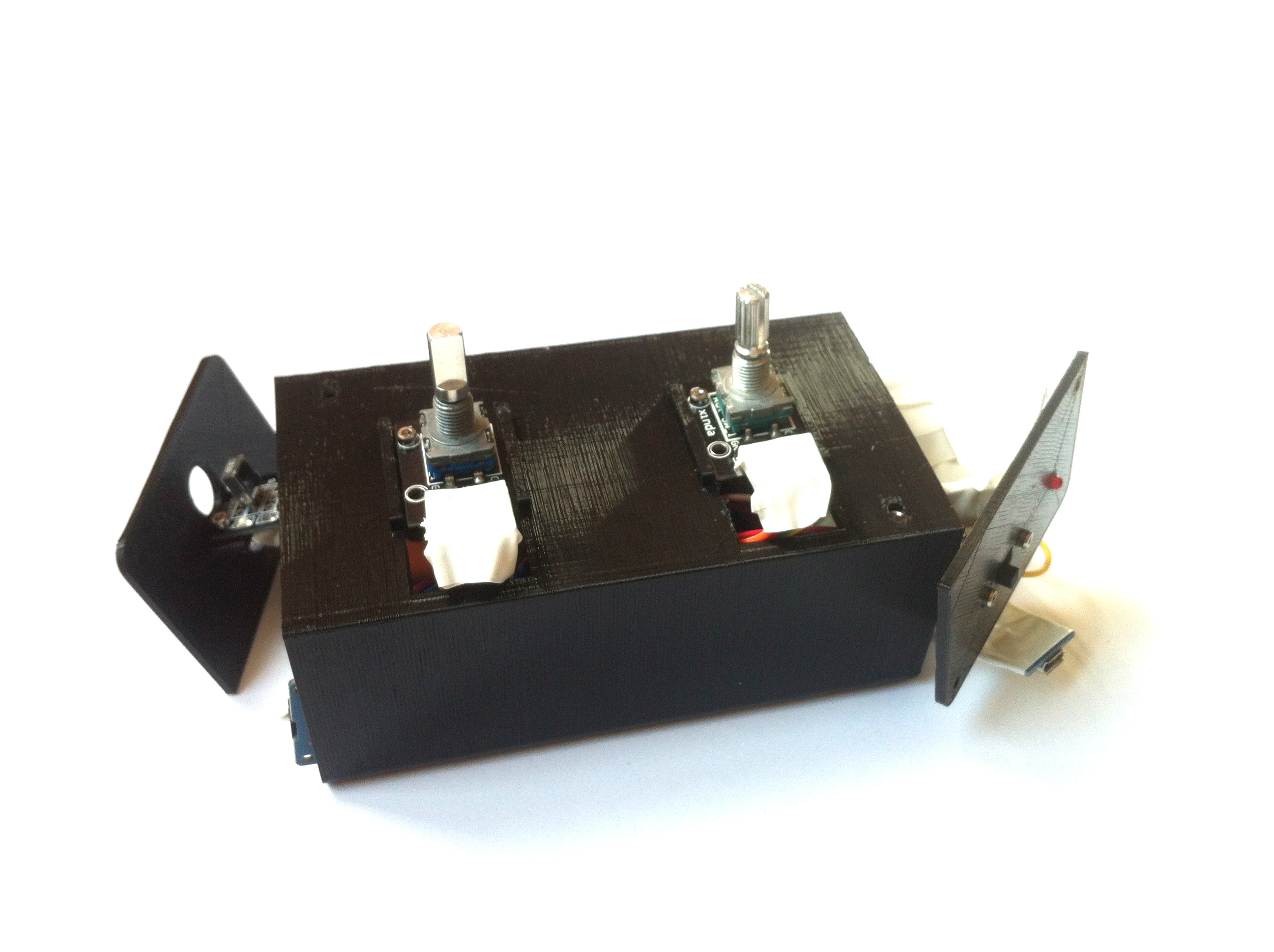
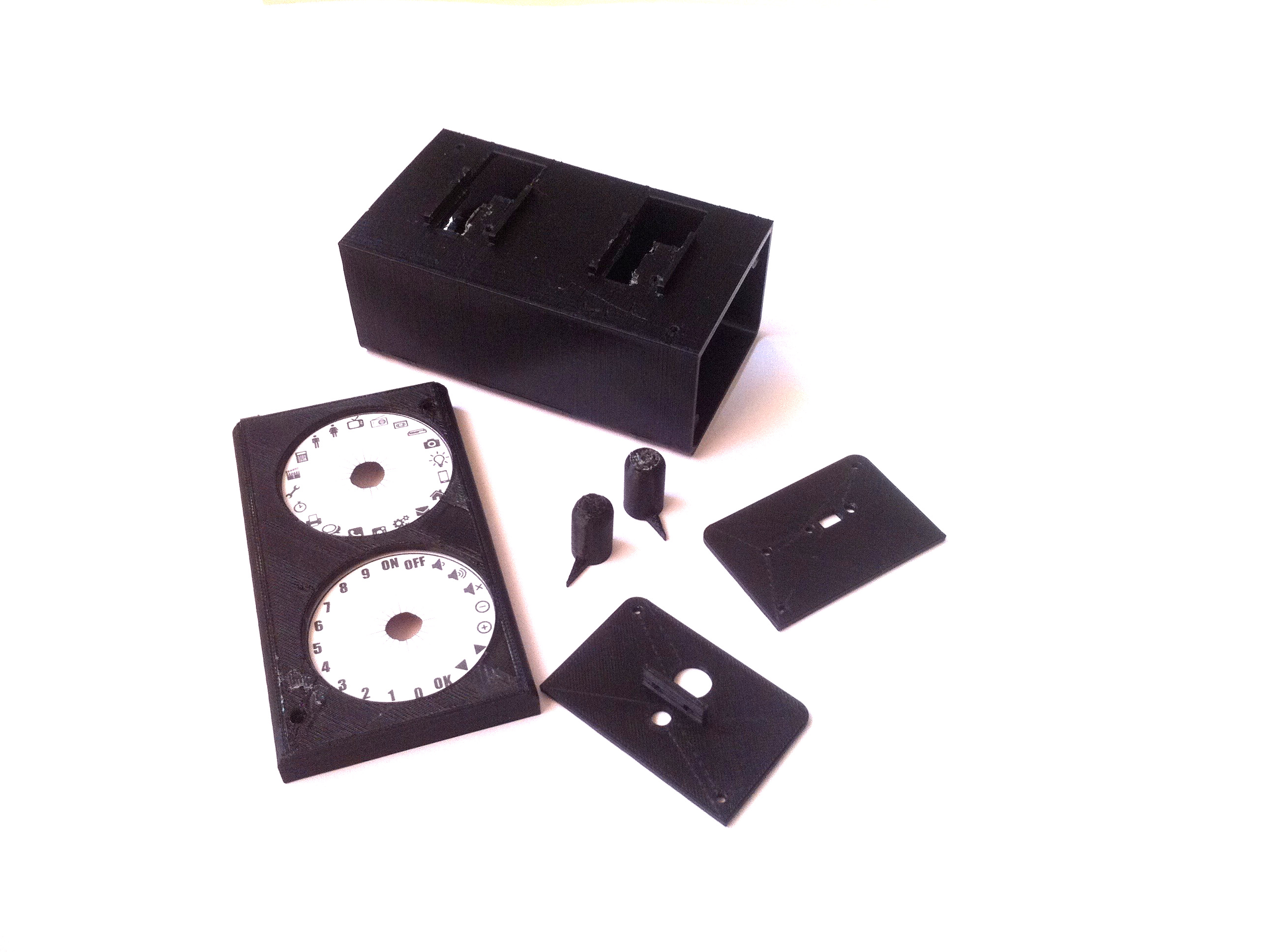
I have also designed a case for the Arduino board and the module. It is really simple, not really aesthetic, but it does the job.
I have left some of the electronic parts free in the box (for example the Arduino board, the microSD card reader), and some were attached to the case with M2 screws (the IR receiver, the 2 rotary encoders, the switch). The red LED and the IR LED are also kept visible out of the case through 2 holes.
To avoid shortcuts, I have placed tape on the metallic parts of the circuits.
I have also designed 2 disks with some pictograms to show the devices to control and the type of control you can do.
And here are the parts that I have designed and 3D printed:
- The body of the case;
- A front panel (with holes for the IR receiver and the IR LED);
- A back panel (with holes for the switch and the red LED);
- And the top panel (with 2 big holes for the disks with the pictograms).
To Go Further
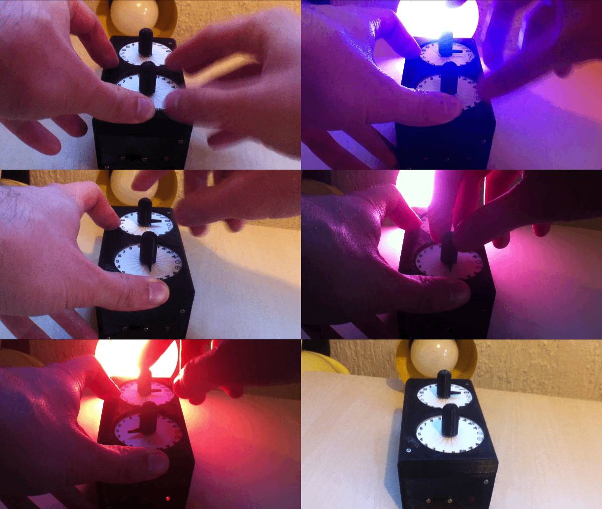
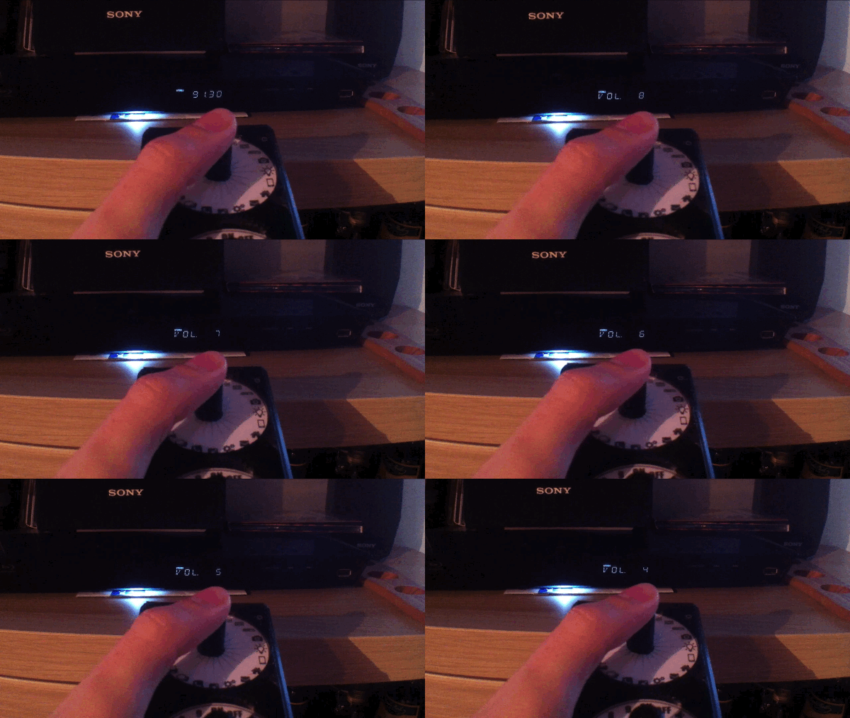
To finish here are 2 gifs showing how I use the remote. You can see that when the I short press the first rotary encoder, the red LED is ON for few milliseconds.
This project was quite interesting for me to make and I am really happy with the final result.
But there are few things that can still be fixed and improved:
- In the code, sometimes the red LED stays ON. This means the loop is stuck somewhere... I have tried to debug the program using some "tags" in the loops (for example I write Serial.println("tag1");), but I never got this issue when I was trying to debug the code. So I guess it is still there, and I will try to fix it later.
- I think the part concerning the short/long press could be easier.
- When I use the remote with the battery it does not work really well to "absorb" the IR signals. It looks like the Arduino board is really slow because the red LED stays ON longer than when the Arduino board is plugged into USB. I guess it probably comes from my boost converter because it allows a maximum current of 250mA, which may be too low... So I will soon change my boost converter to fix this problem.
- And finally, I think the plastic case is a bit too big, and the circuit inside is messy. Maybe it would be better with PCB? And smaller case with specific places for each module?
Note: it is important to always place the arrows in the same position before to start the remote. Why? Because when you start the remote, the rotary encoders have the value 0. So if they are in different positions, the 0 are not at the same place than before.
Anyway, I hope some of you are interested in this project and will try it!
Again, if I made any mistake, feel free to correct; and if you liked this project comment, share & like! :)