Universal 3D Printer Automatic Shutdown System
by Mikagu in Circuits > Arduino
628 Views, 7 Favorites, 0 Comments
Universal 3D Printer Automatic Shutdown System
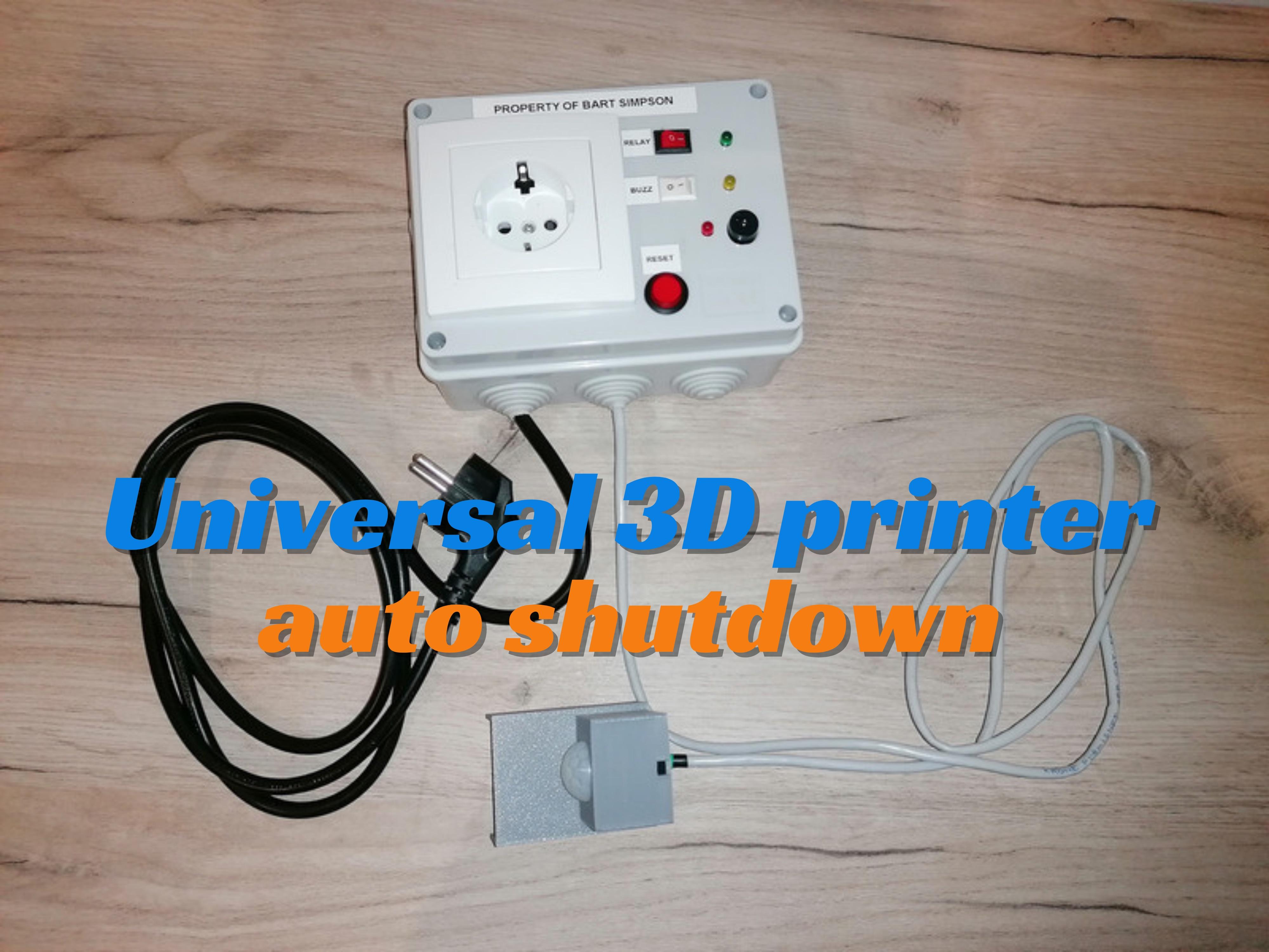
I've developed a project using Arduino to address the absence of automated shutdown solutions for 3D printers. Recognizing the need for a reliable system to enhance safety and energy efficiency, I designed a setup that automatically shutdown my 3D printer after finishing the printing (when there is no movement detection, to be exact). By integrating a PIR sensor and a timer based on Arduino programming, the system will notice when the printer has stopped and will perform a shutdown once the “cooling time” is achieved.
Main advantage is that this setup is universal for any 3D printer as it does not interfere with the 3D printer electronics. It will be the 3D printer (or any other device) which will be plugged into this device, so no modifications are required on your printer (apart of properly attaching the PIR sensor to it). Normally, I plug to it a 3-socket splitter so I can power the 3D printer, my WIFI camera and a light during the print, and everything is powered off when complete.
Supplies
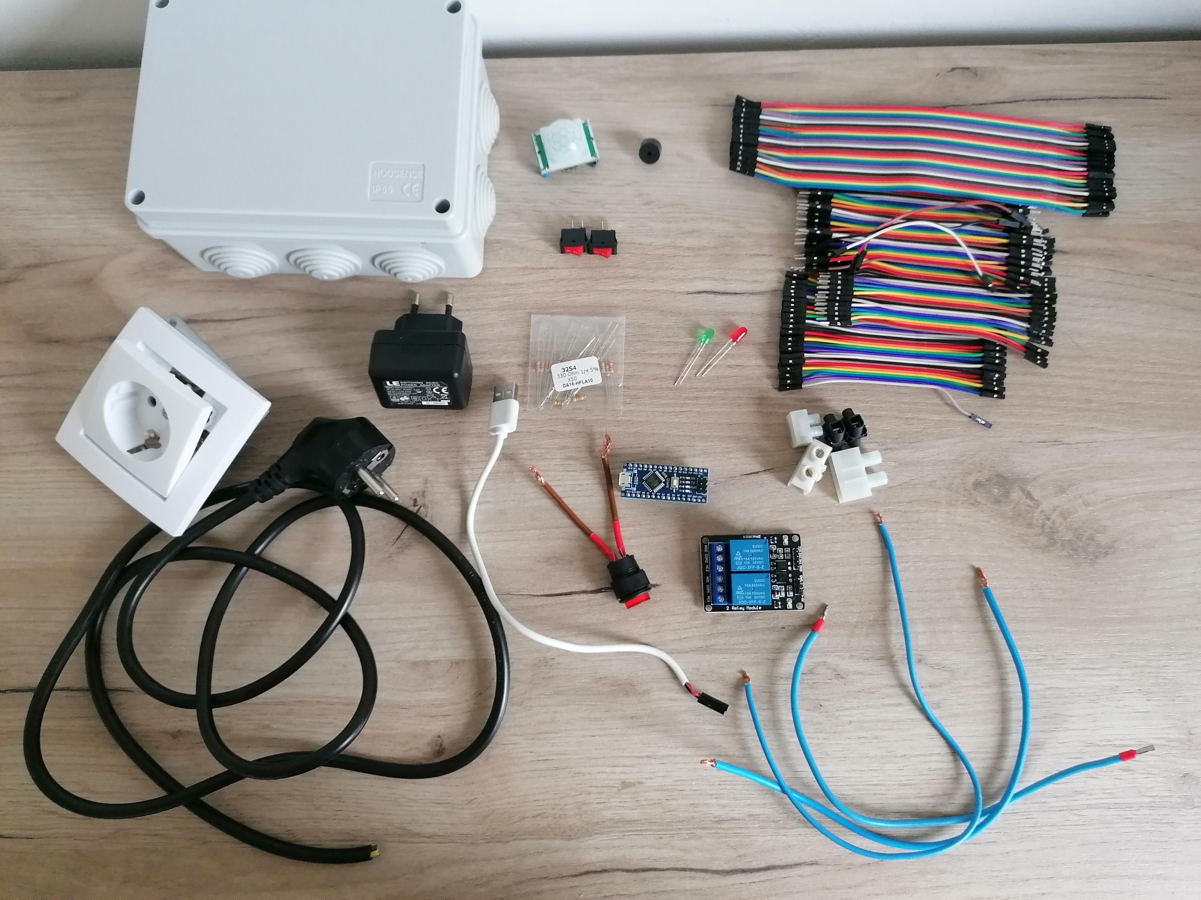
BOM
- Box: I've chosen an ABS plastic box
- Electric socket
- Power cord
- 5v DC power adapter
- USB to USB micro cable
- Electric wire (for the AC connections)
- Cable connectors
- Arduino Nano (or any other)
- PIR Sensor
- 1 channel relay 5v (is it not required to have 2 channels as in the image)
- LEDs
- 330 ohm resistors for the LEDs
- 5v active buzzer
- Push button (for the reset)
- 2 Switches (one for the buzzer and one for the relay)
- Jumper wires
Box Preparation
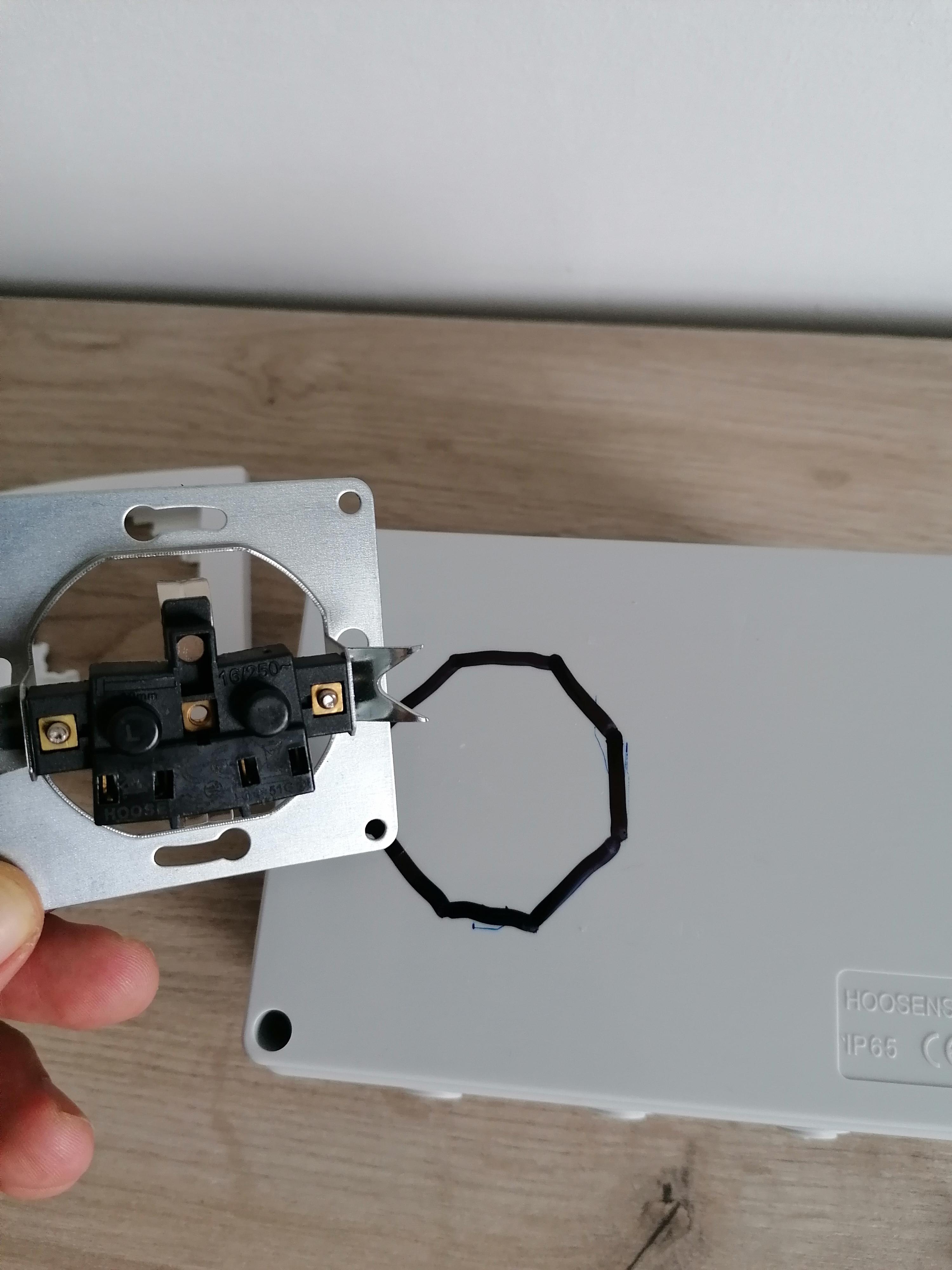
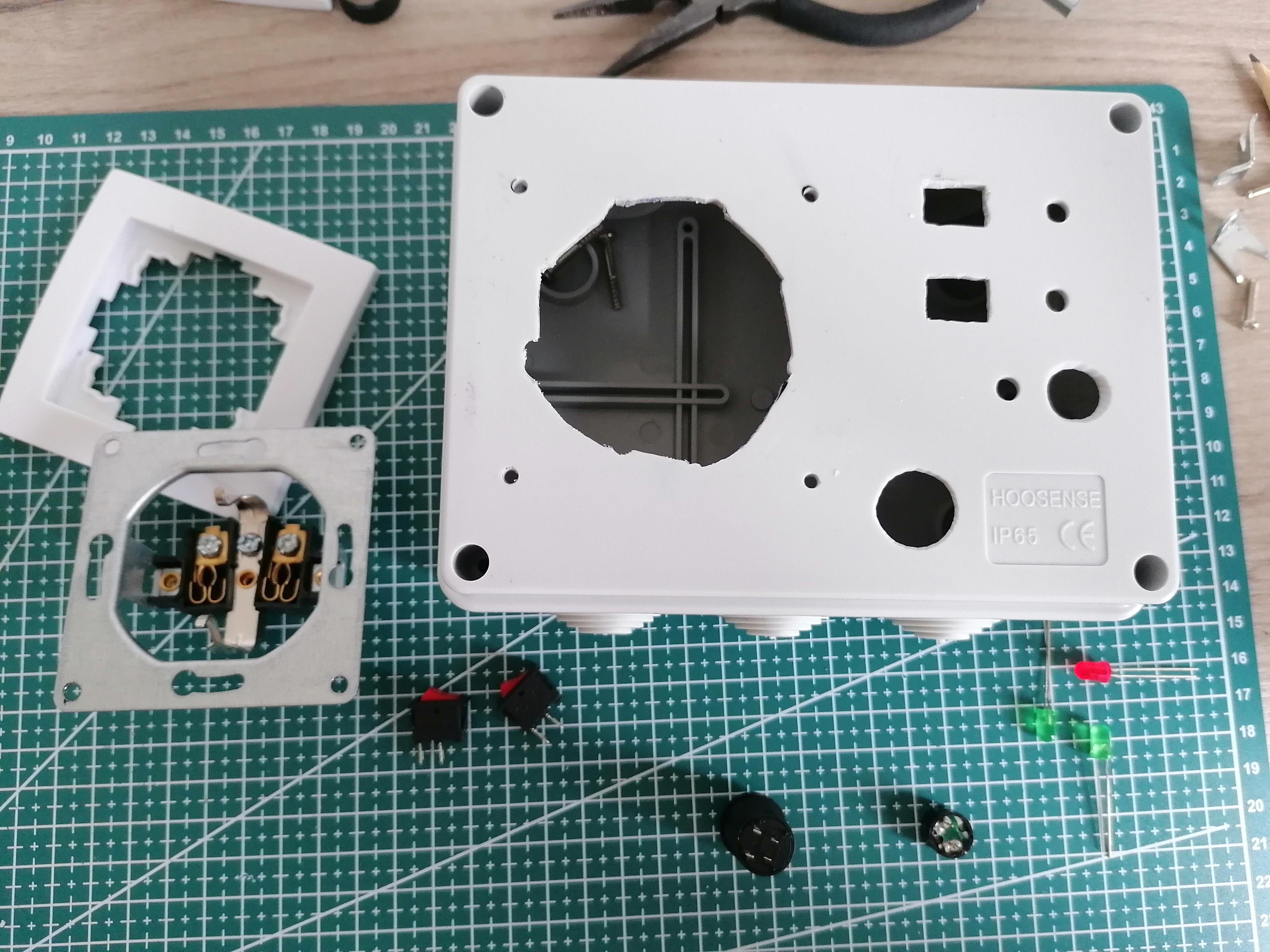
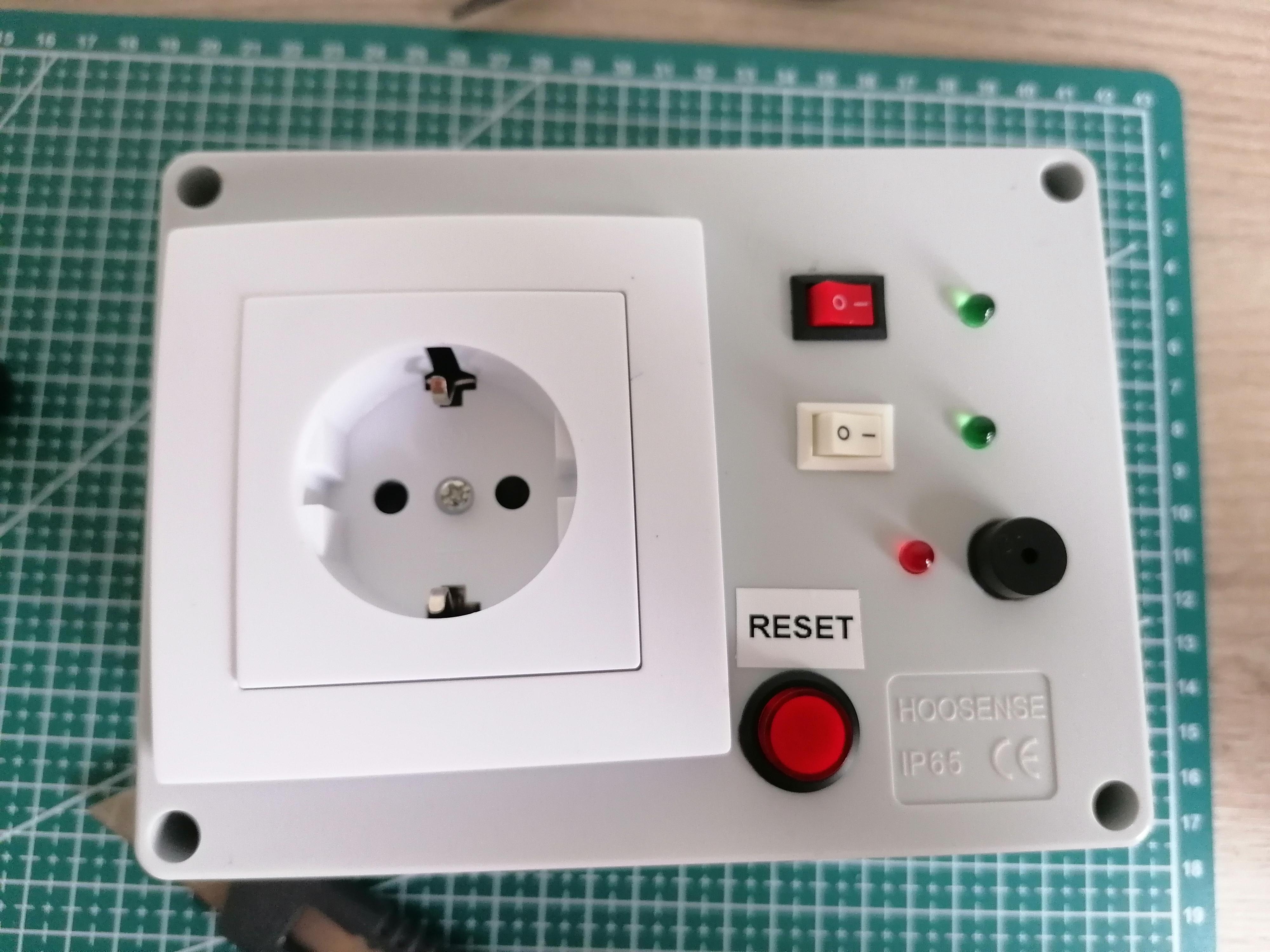
Once you have gathered all the components specified in the Supplies list, it is time to start assembling it.
The main advise to give you is to choose a proper size of the box, as you'll need to fit everything inside while making sure that there won't be any live wires or connections in contact. This is really important as you'll be mixing 230AC (depending on your country voltage) with Arduino voltage. I've isolated the power relay in a 3D printed box to make sure that its soldered pins cannot interfere with other cables.
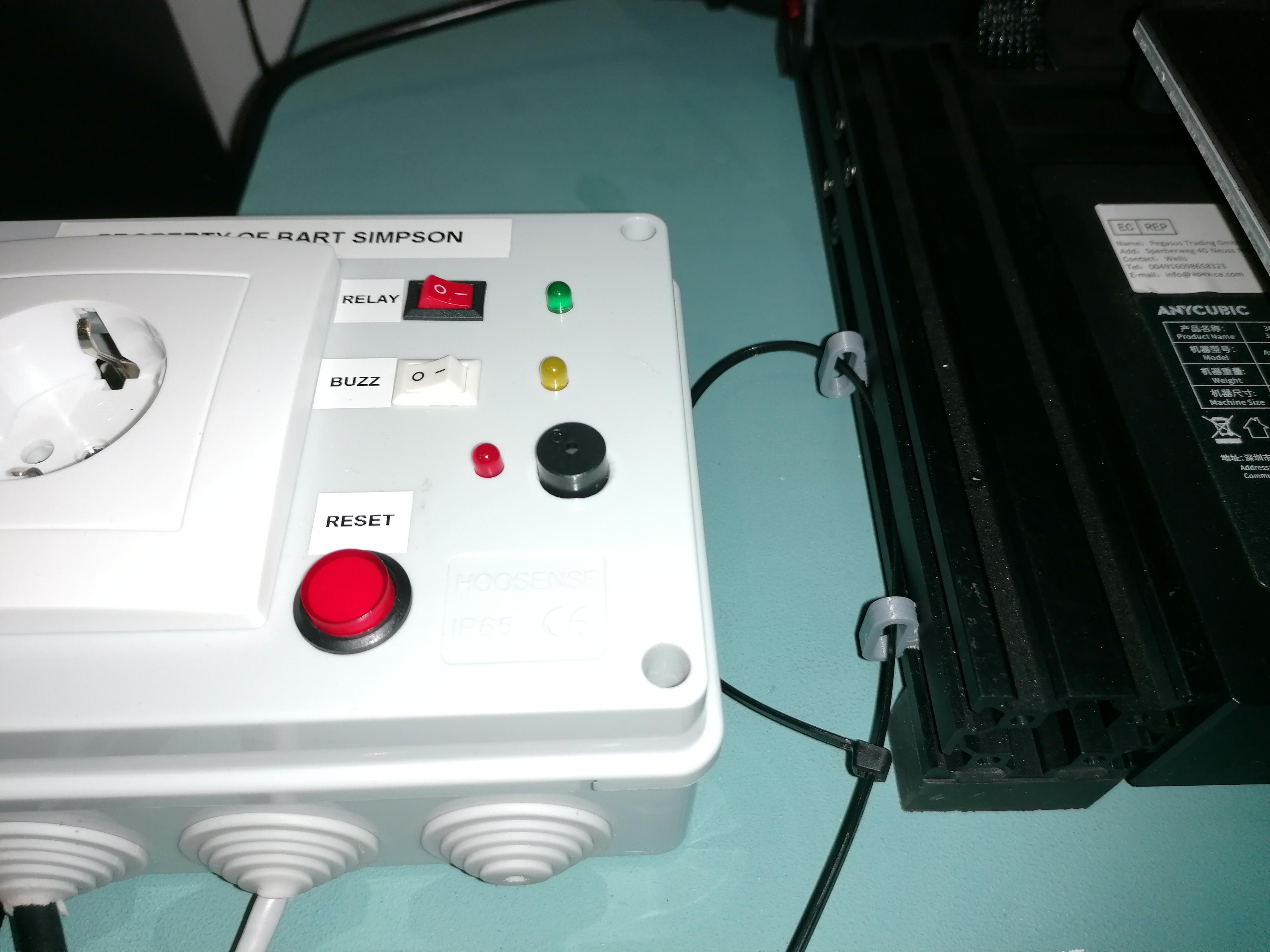
After choosing a box, start by making the holes in the cover to put the power socket, the LEDs, buzzer, switches and reset button.
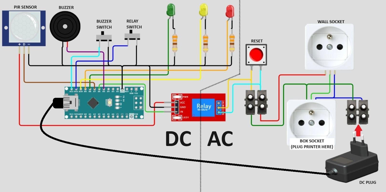
The Circuit (Part 1 - AC Connections)
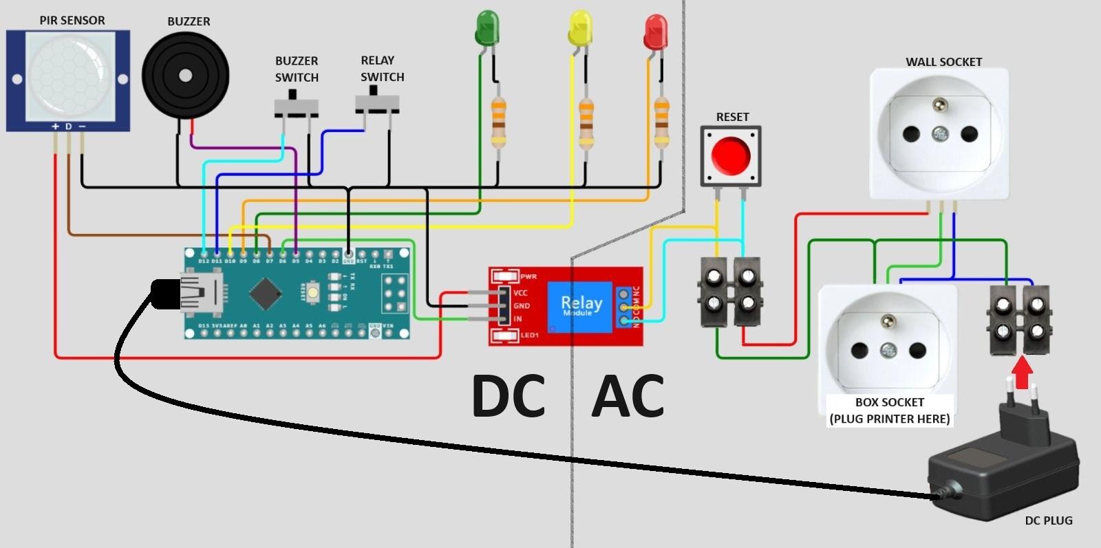
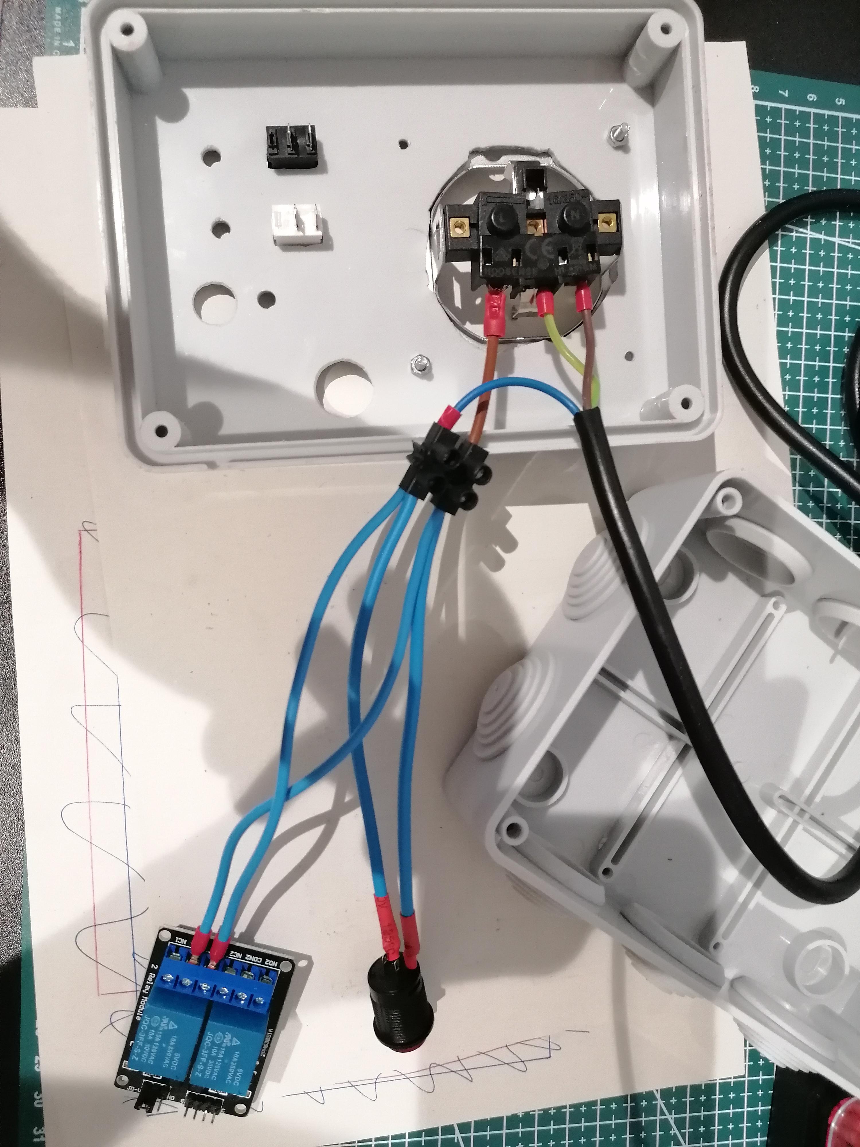
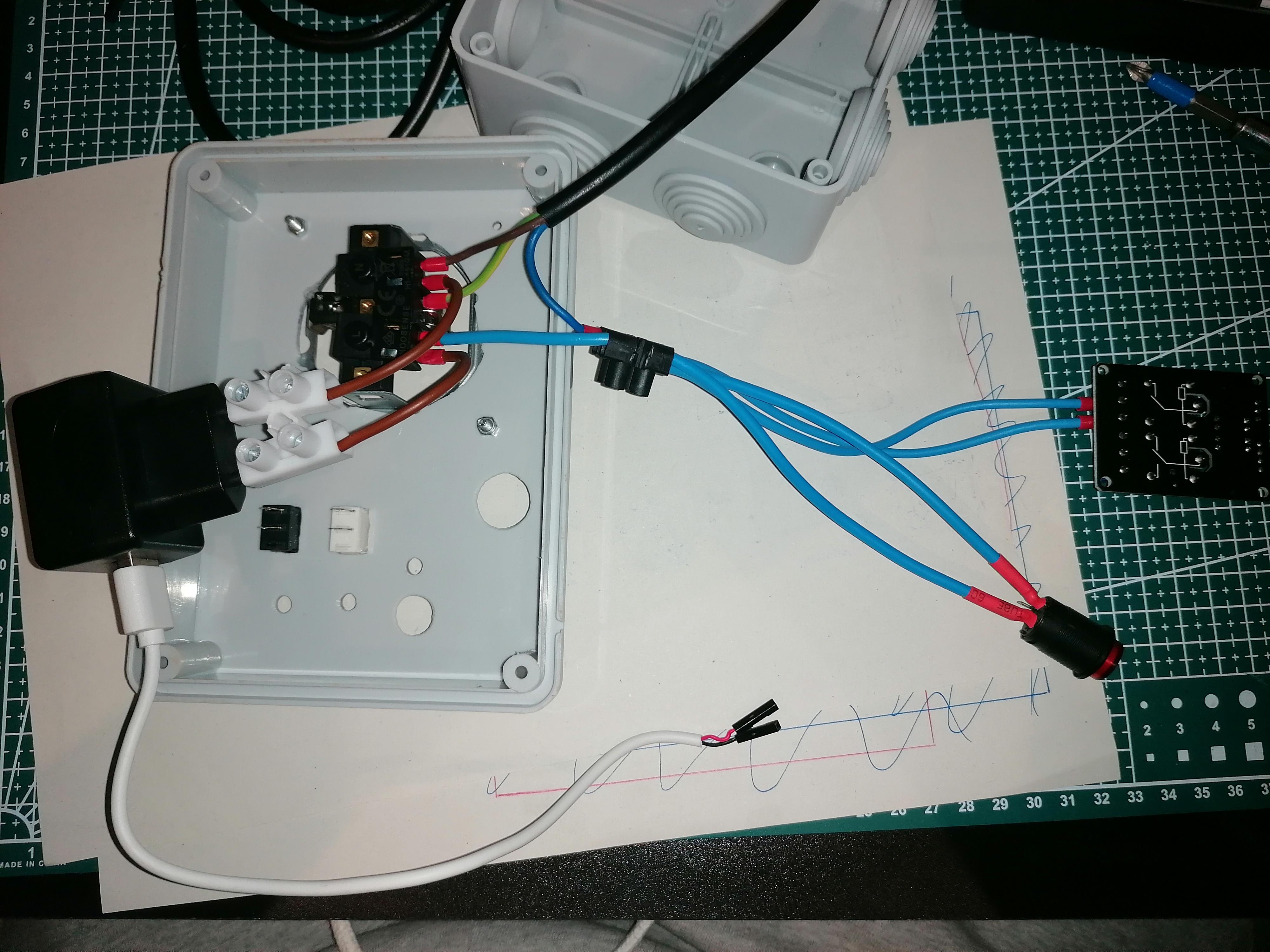
This part is quite simple. Relay and reset will close the circuit when activated, enabling power to socket on the box. When the relay powers off the circuit, there won't be any power consumption.
Relay and reset button are wired the same way as they have the same functionality: Reset will start the circuit and the relay will keep it powered while it is active.
In case you choose a bigger box, you can isolate AC and DC circuits properly.
The Circuit (Part 2 - DC Connections)
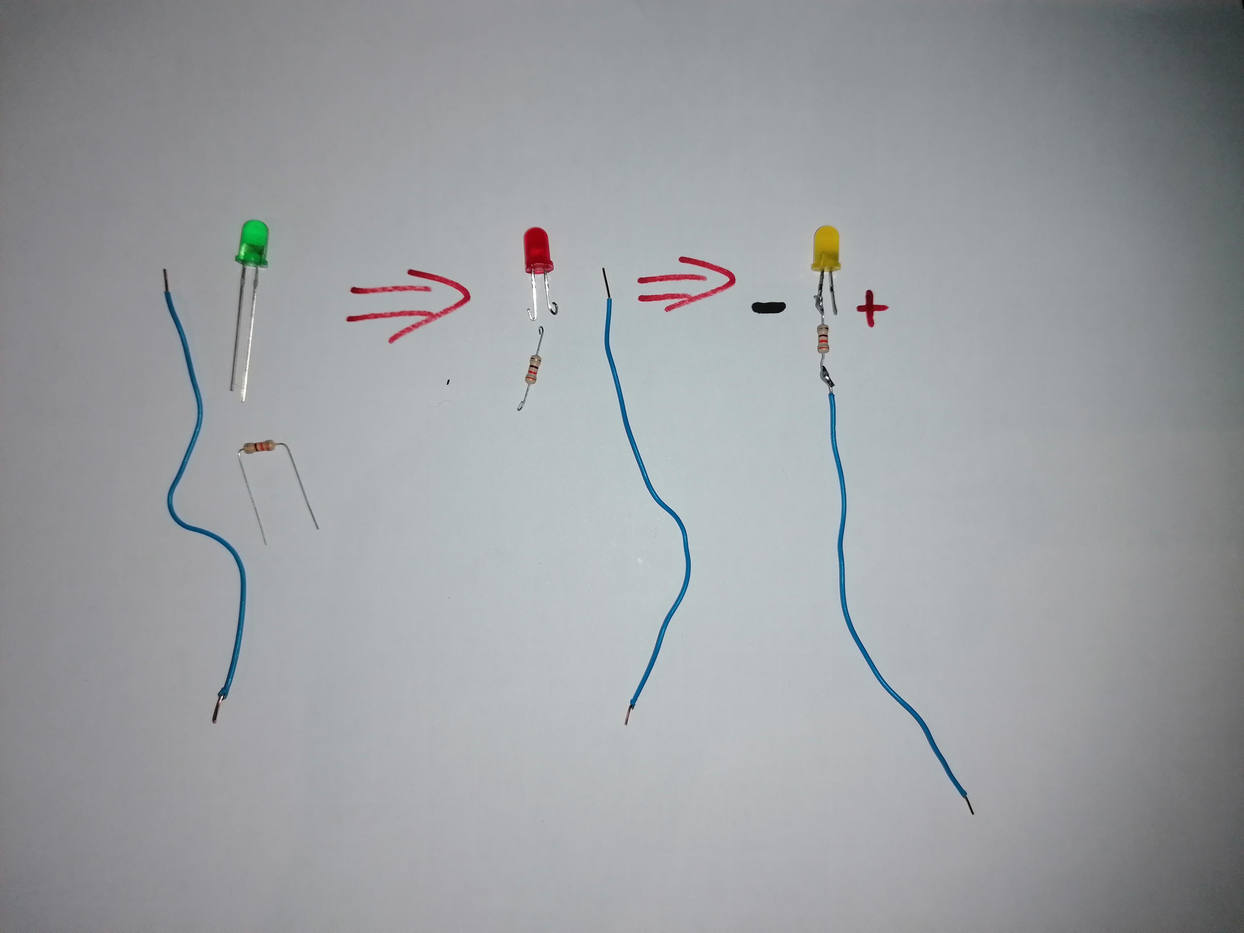
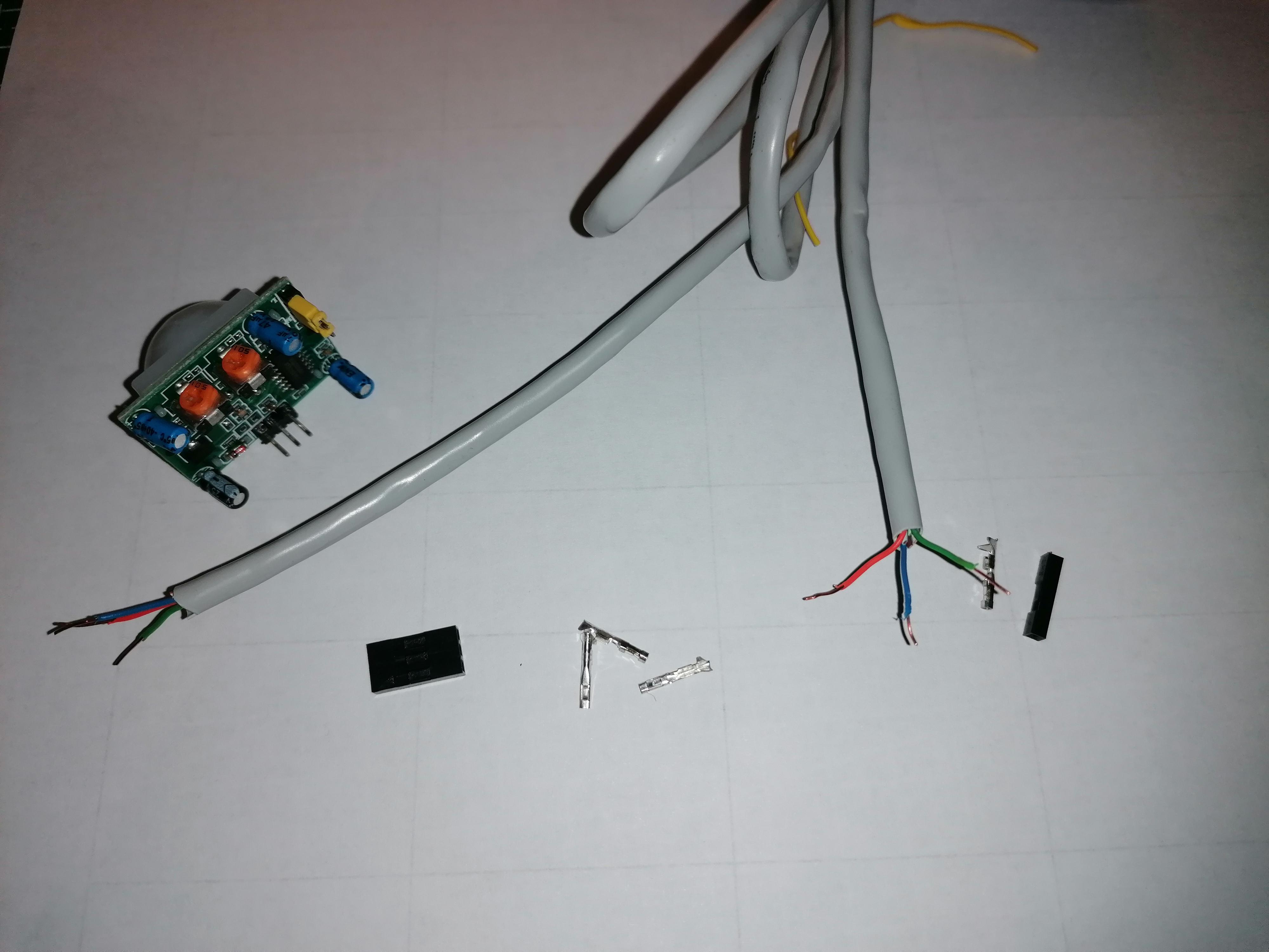
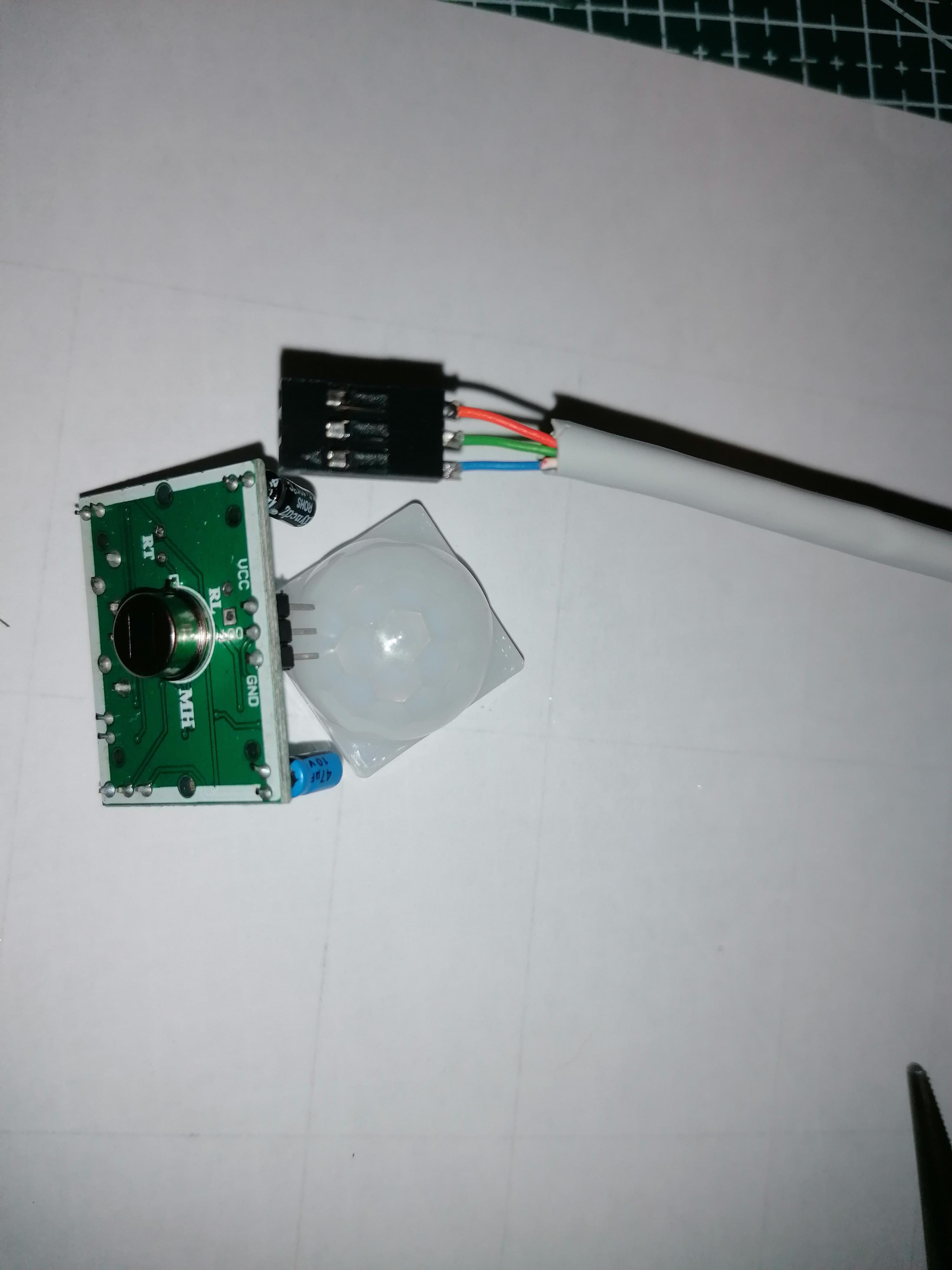
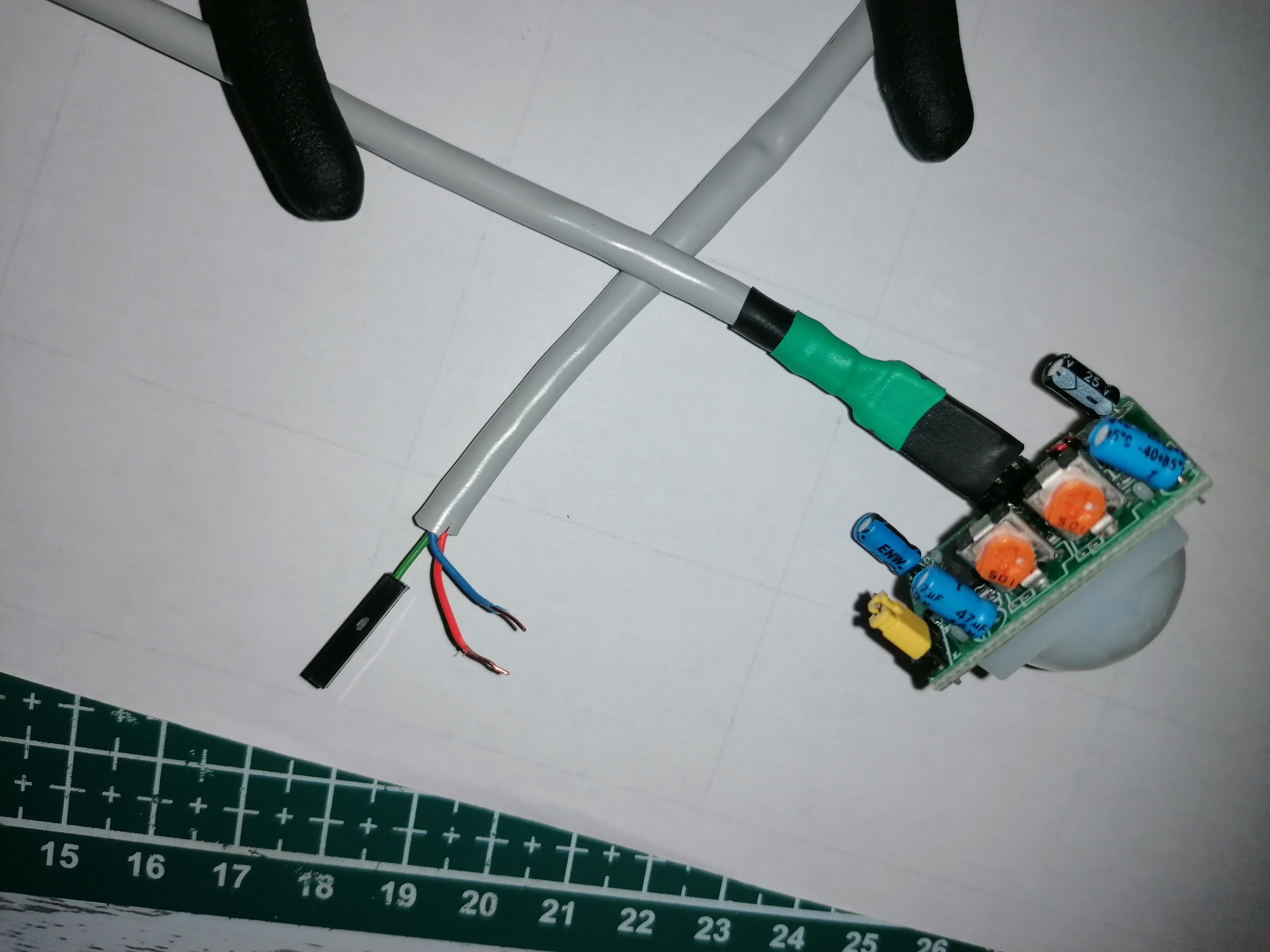
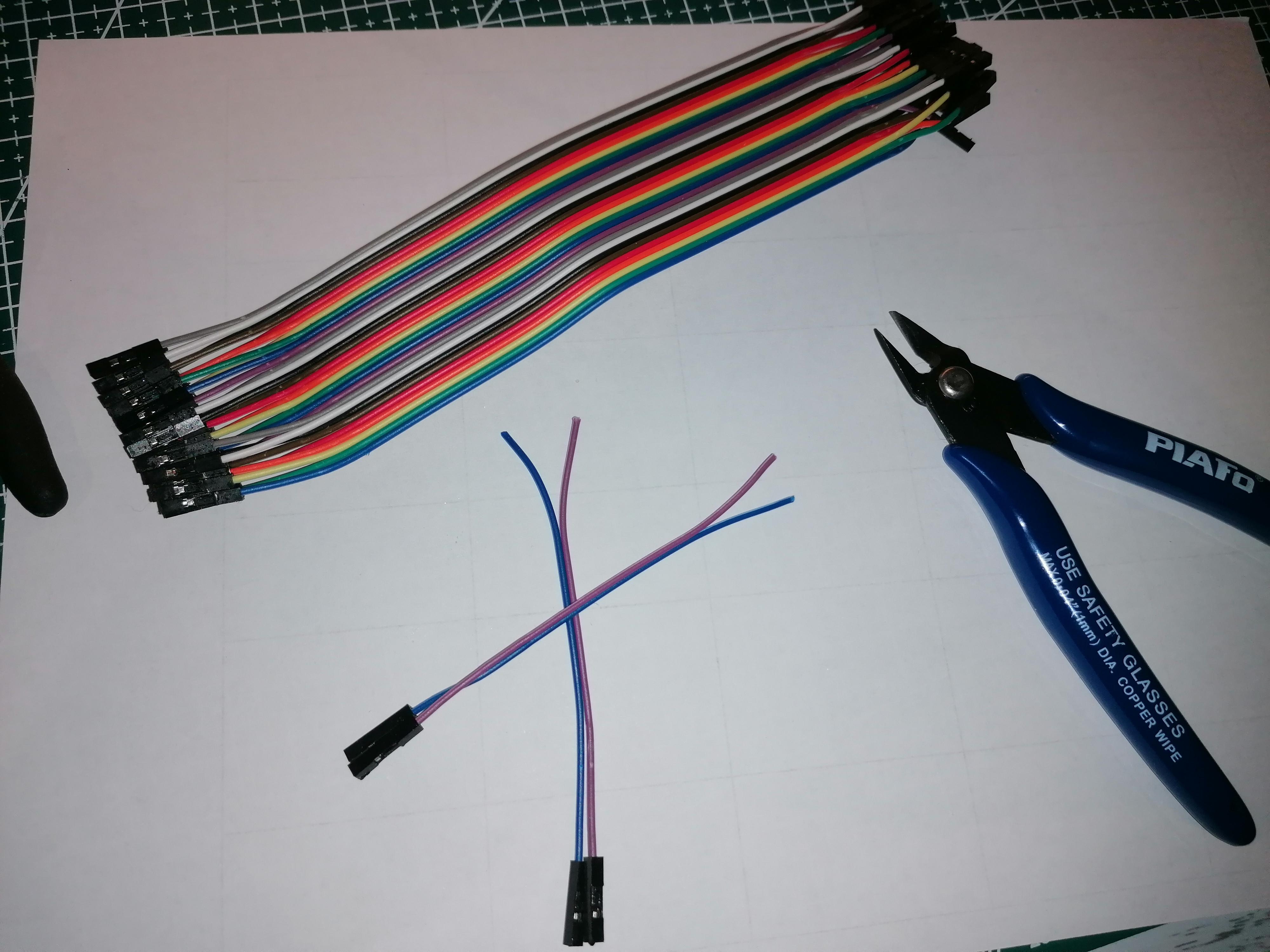
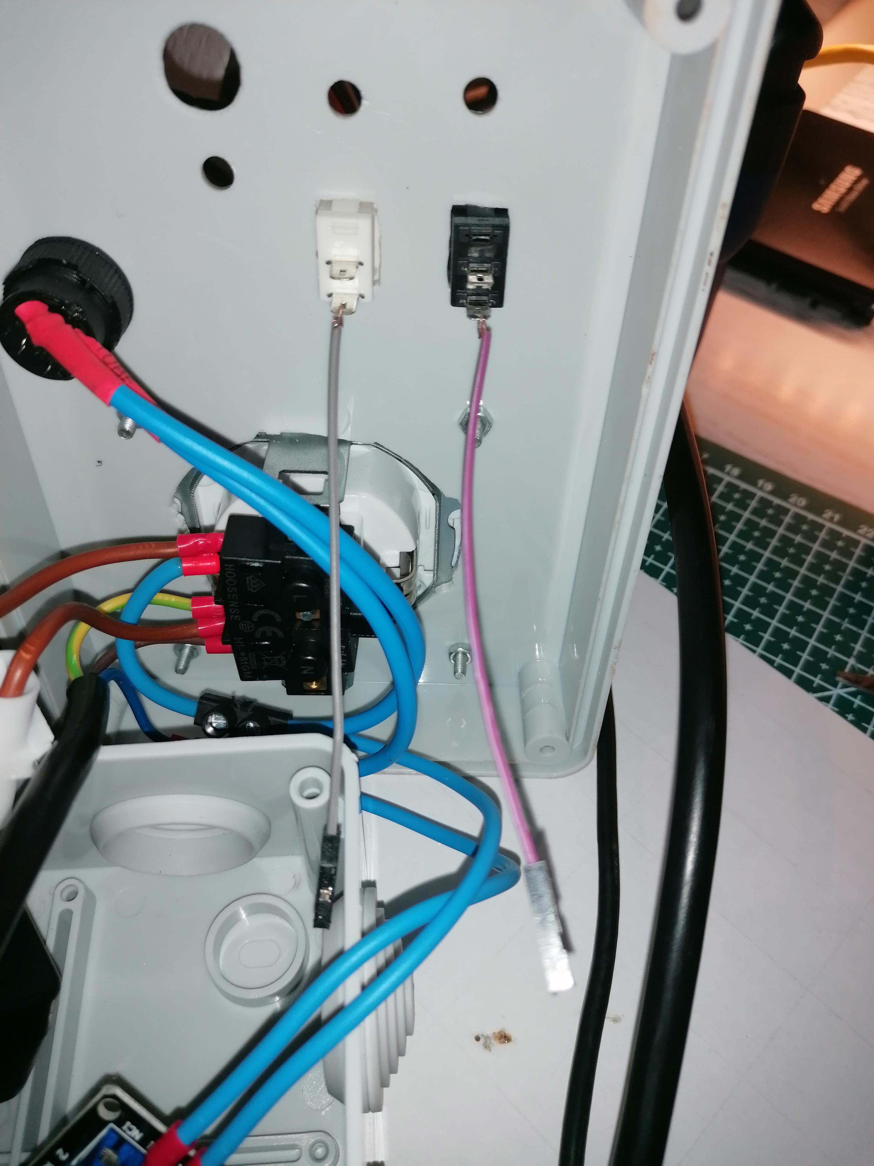
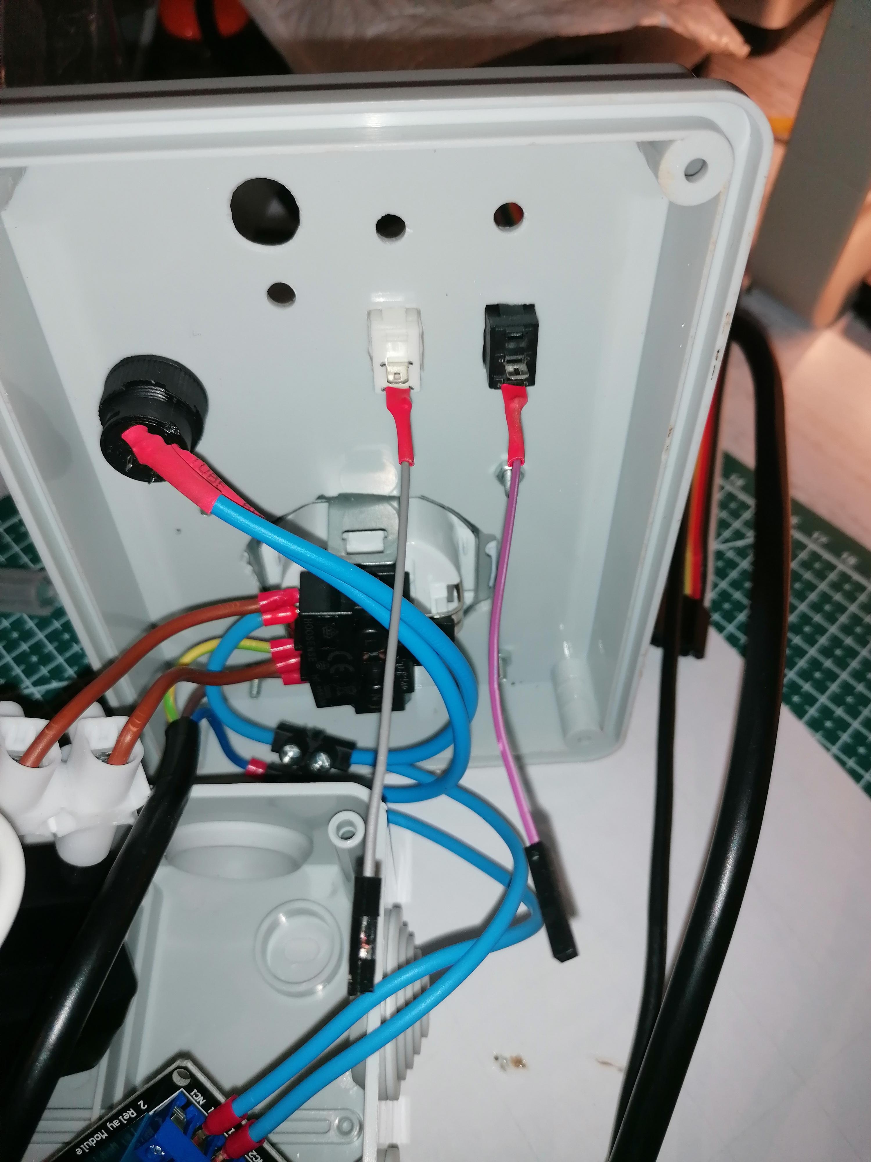
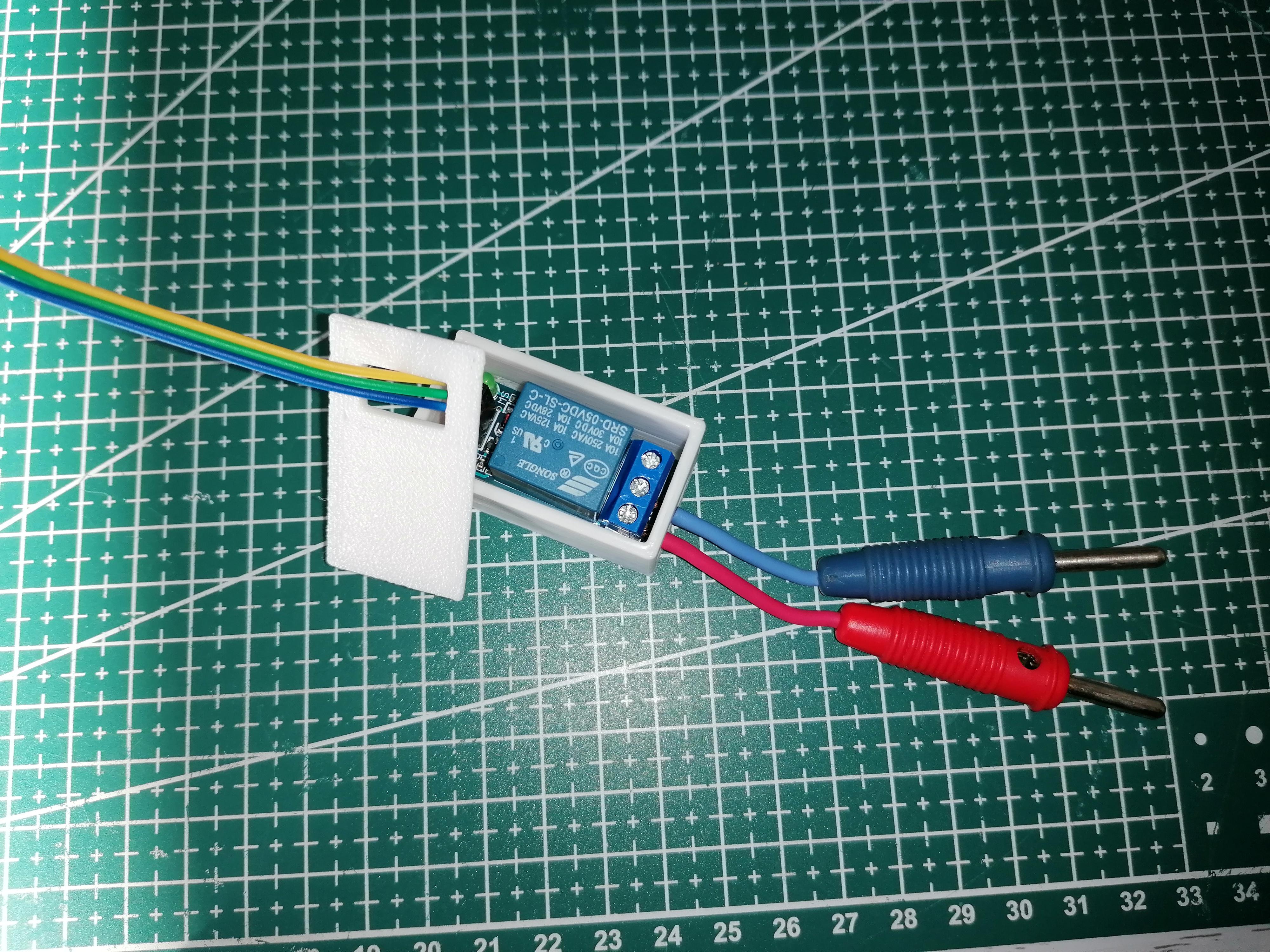
Now it is time to solder and wire everything by following the diagram. I highly recommend to put heat shrink tube protection to all your soldered unions.
For the LED, you must add a 330Ω on the negative terminal.
For the PIR cable, make sure you make it long enough as it should be attached on the printer Z axis afterwards.
Buzzer and relay switches do not need a resistor as I'm using the INPUT_PULLUP pin mode in the Arduino sketch.
For the relay, I've put it inside a 3D printed box to isolate it: LINK
Upload Sketch to Arduino

Inside the sketch, in the Variables definition, you'll see that I've put some tips on the duration for the different functionalities.
Before securing the connections with hot glue (I like to make sure everything will stay in place once we close the box), I recommend to upload the sketch to your Arduino with the "TEST" values, to test how it works.
Test parameters:
- DownTimeShutdown: TEST: 30 - STD: 360 // (in seconds) maximum time allowed until relay will power everything off. I've put 6 min to ensure the printer cools down on it's own before powering it of, as the fans help on cooling.
- TimeBuzzStart = 15; // TEST: 15 - STD: 60 // (in seconds) time for the buzzer to be turned ON after no movement is detected
- DownTimeLed = 10; // TEST: 10 - STD: 30 // (in seconds) time for the red LED to be turned ON after no movement is detected (Added this to avoid intermitent detections from the PIR sensor)
The sketch I'm providing has the standard values defined by default, so you must change it for the TEST value.
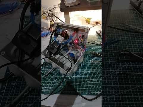
I'm linking a video I made during this test but check the one in the last step for a better demonstration.
Downloads
Finishing the Circuit
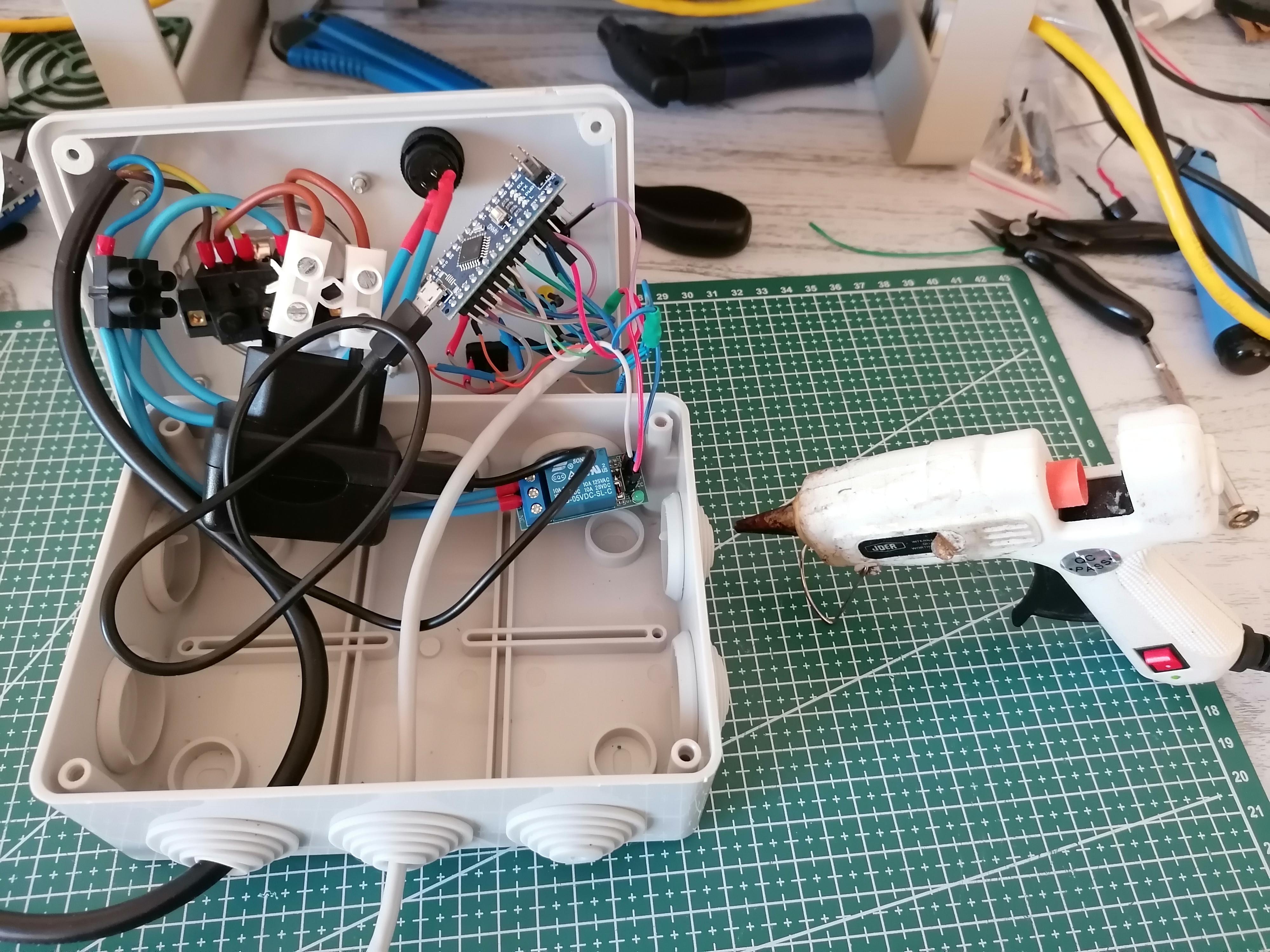
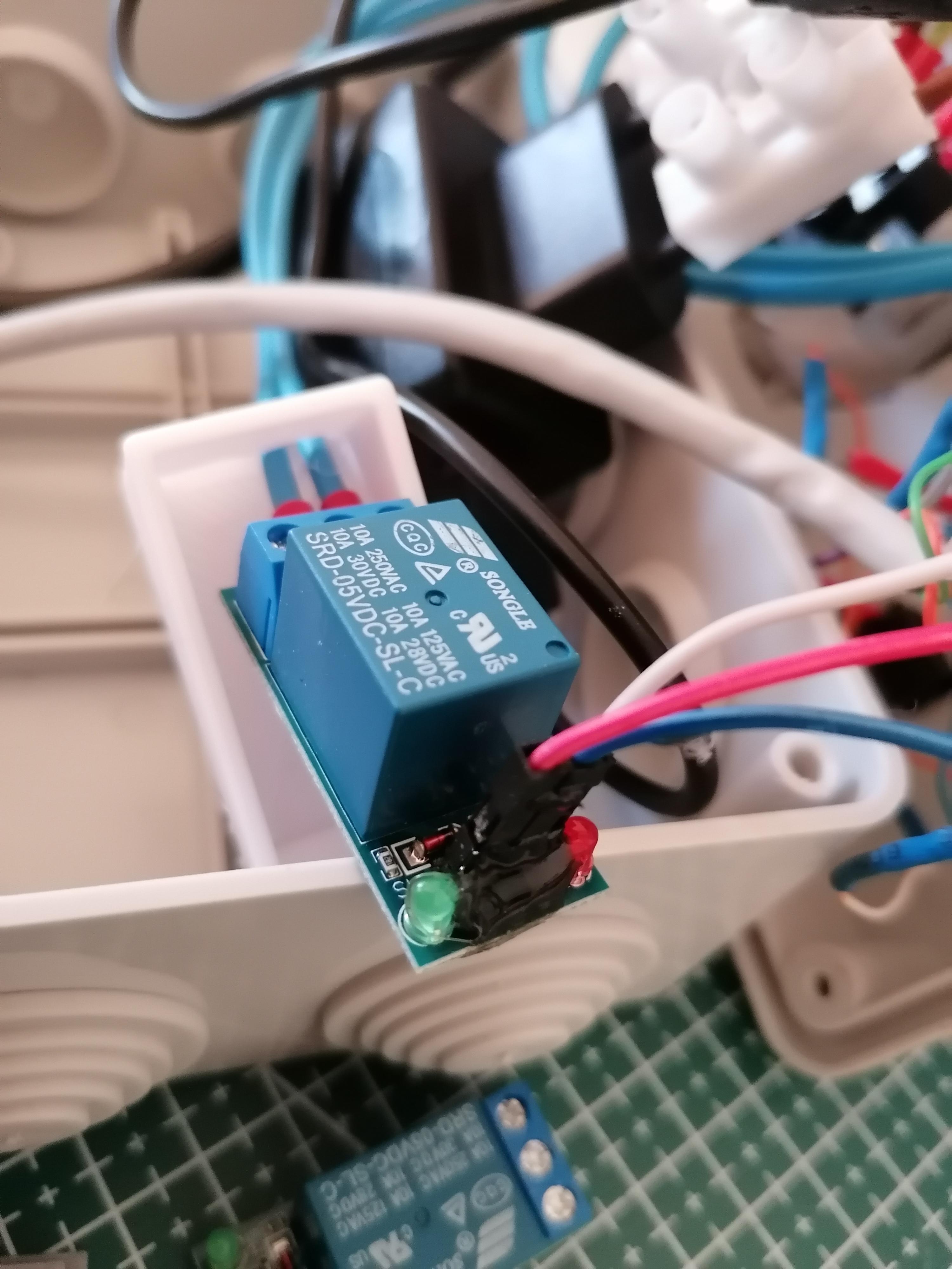
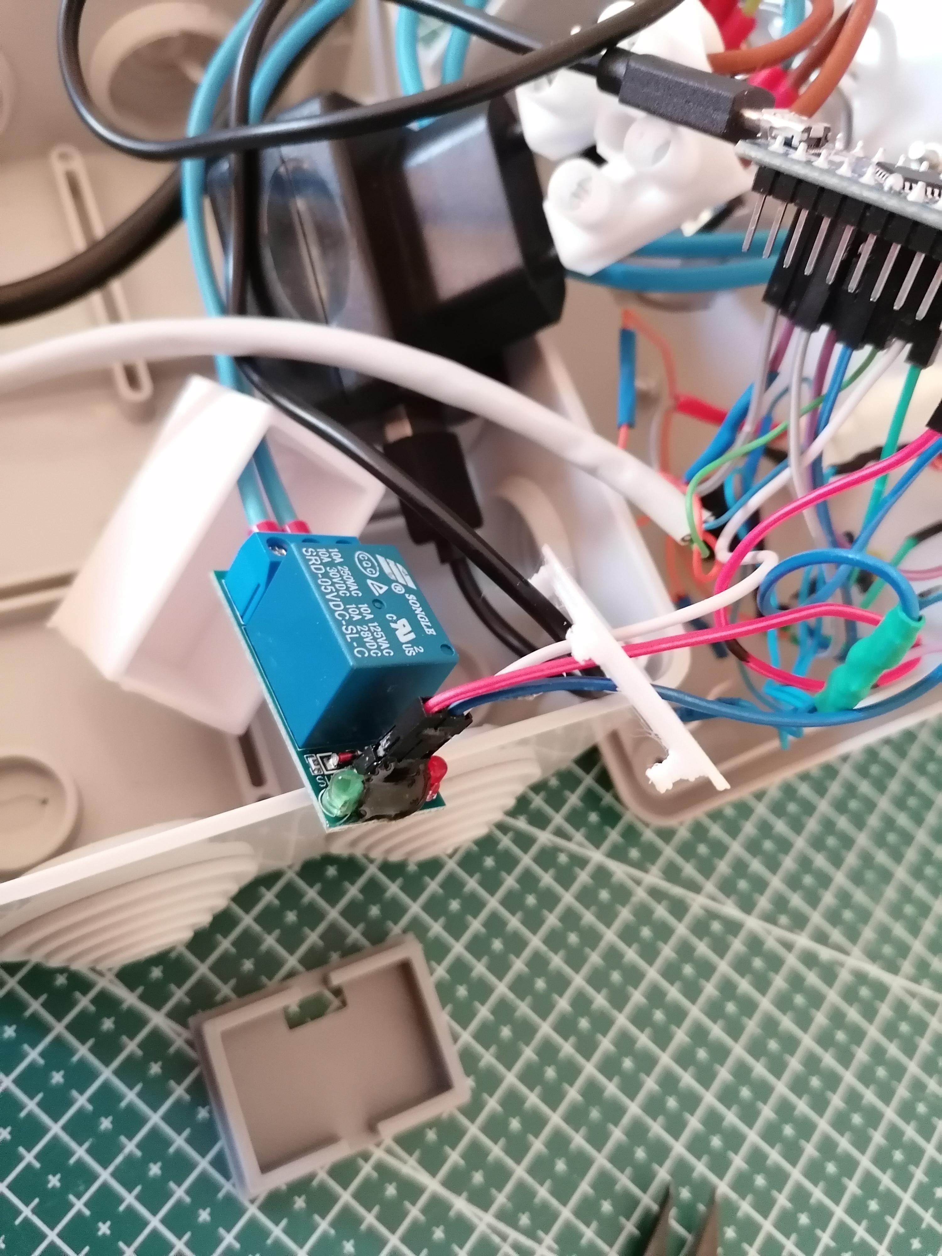
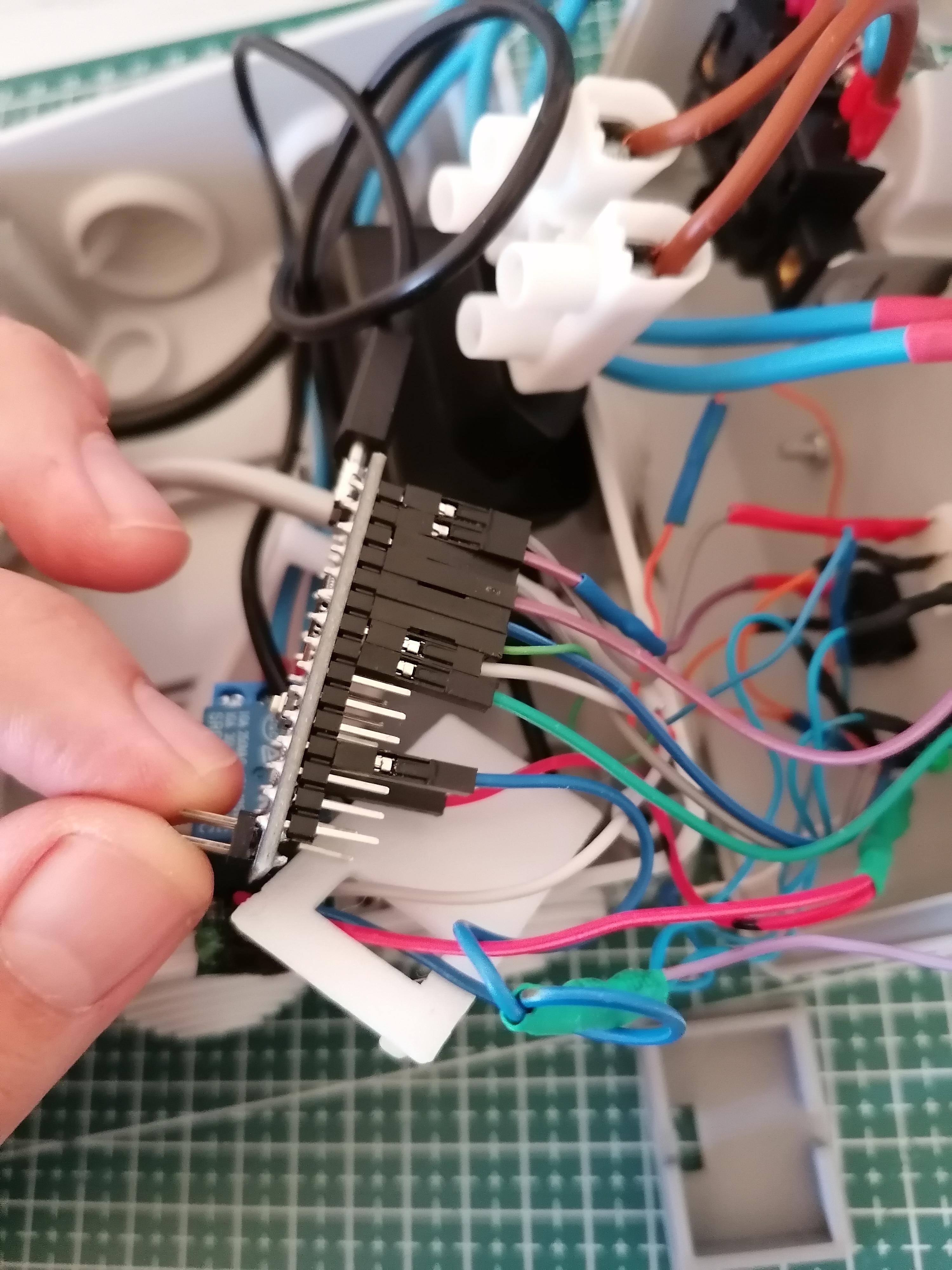
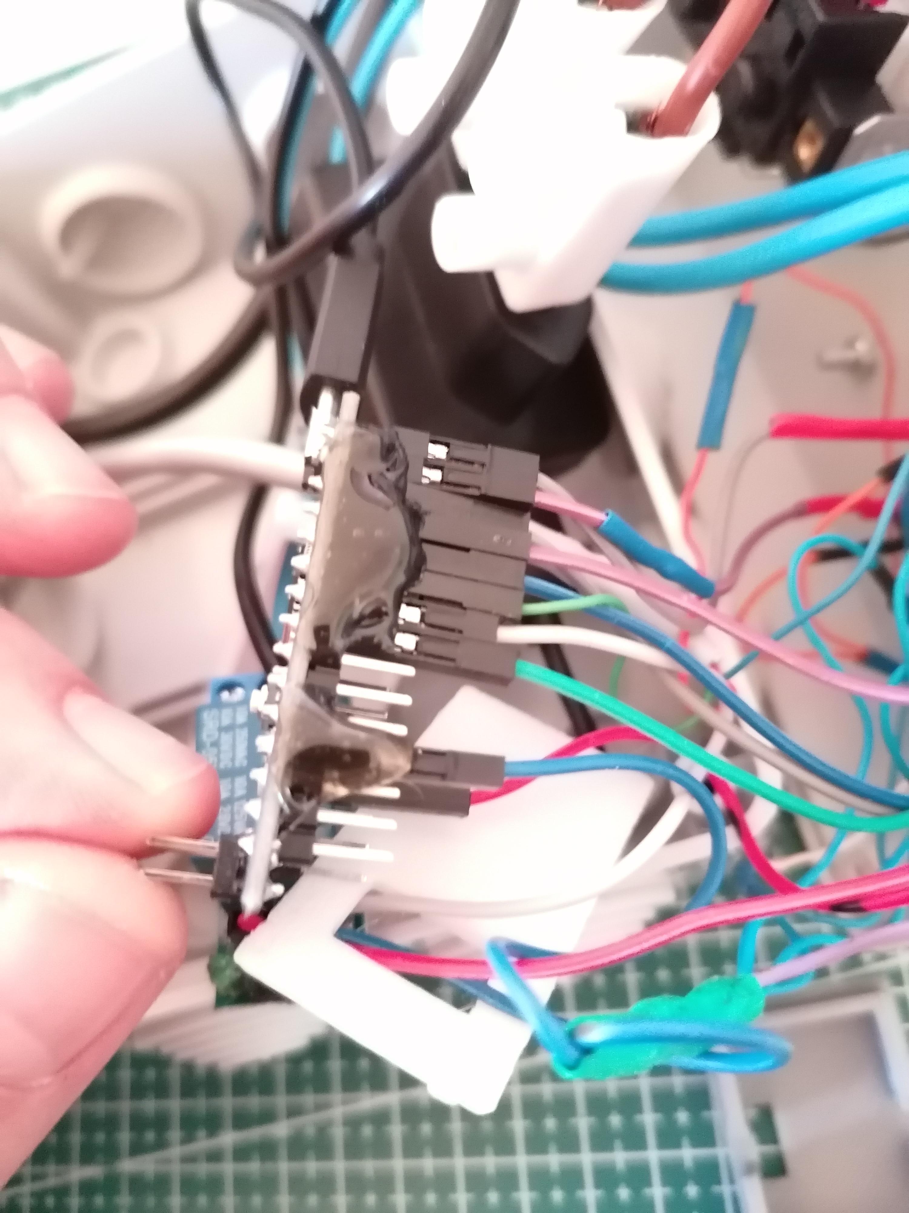
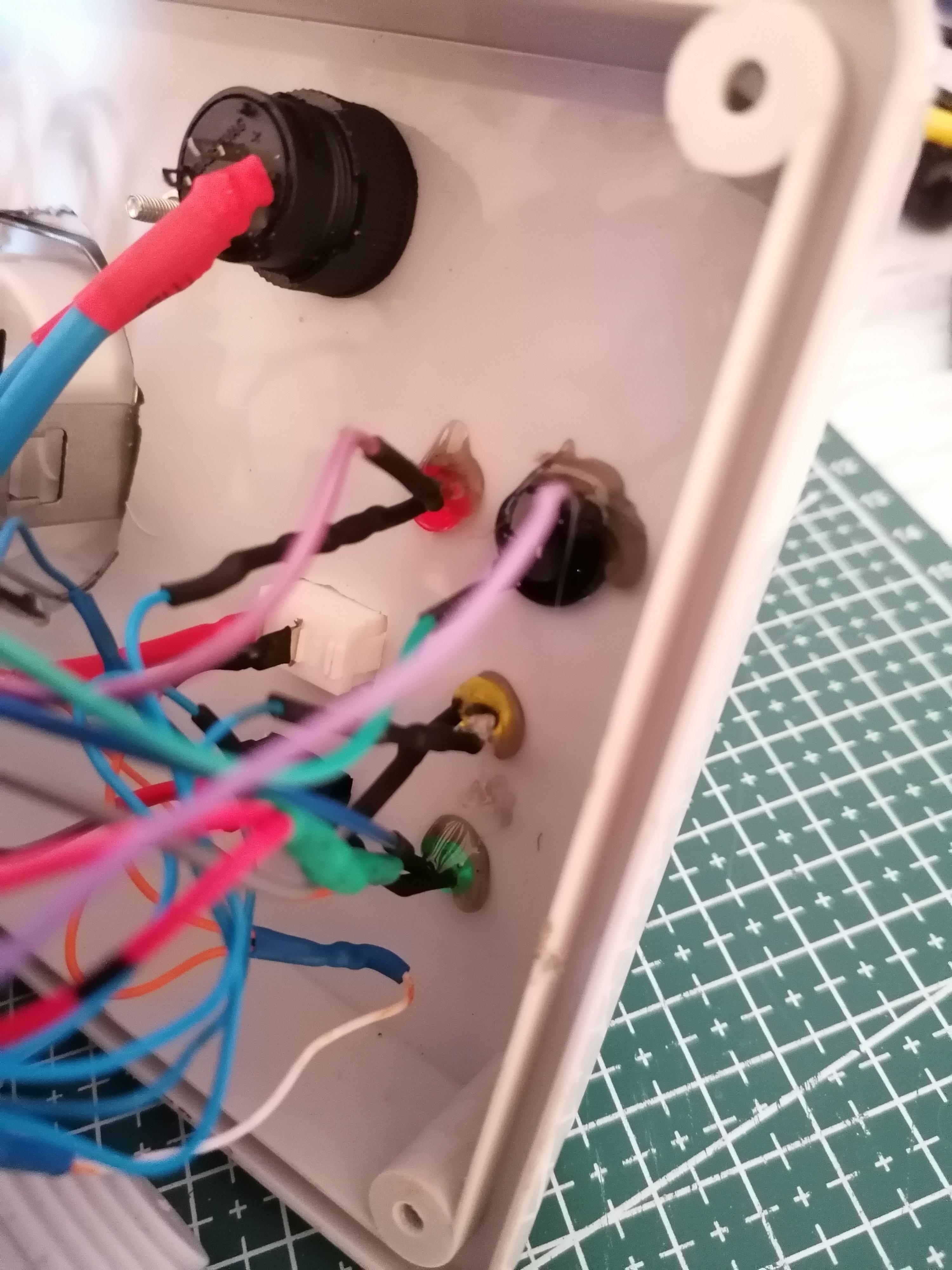
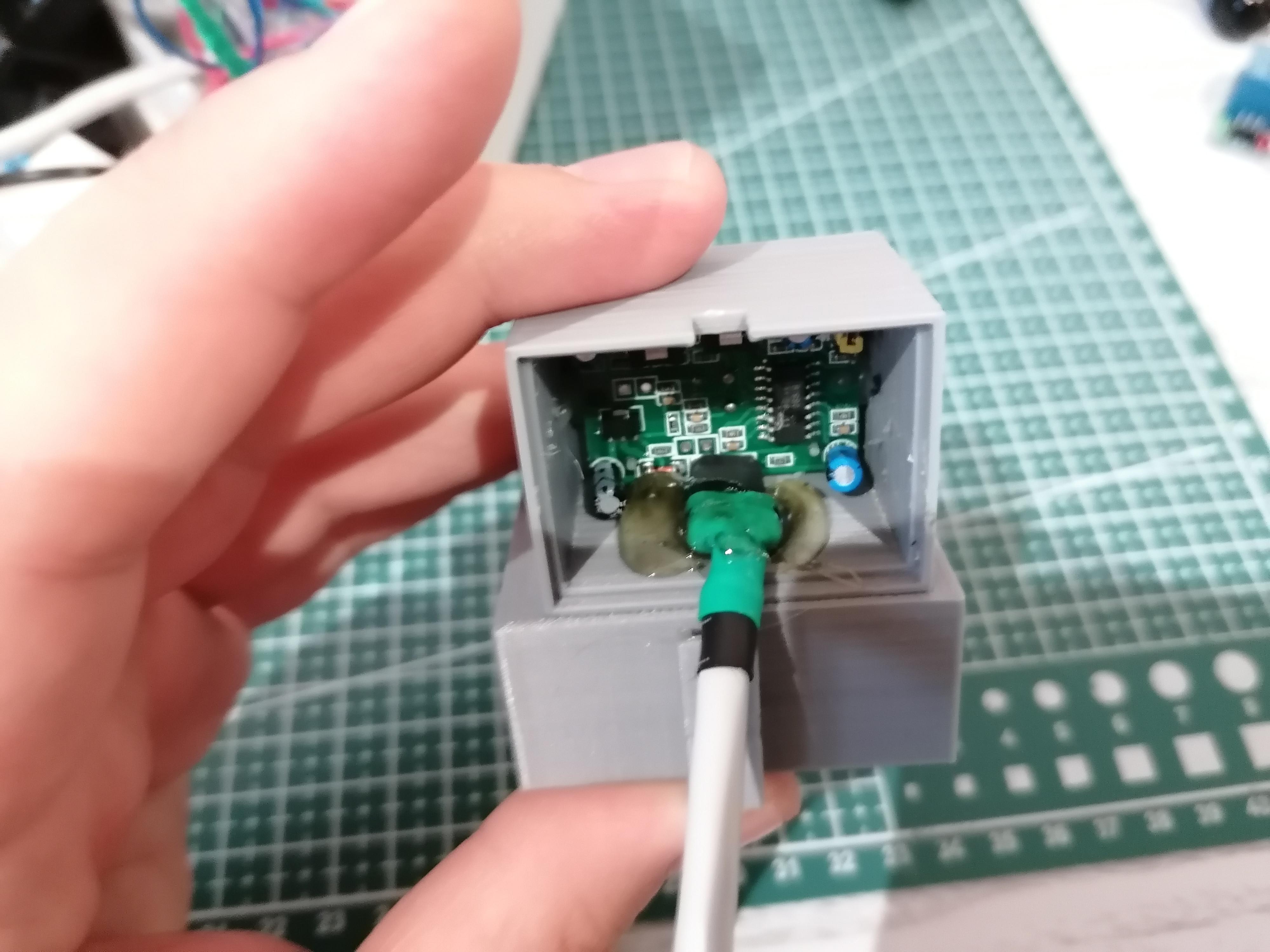
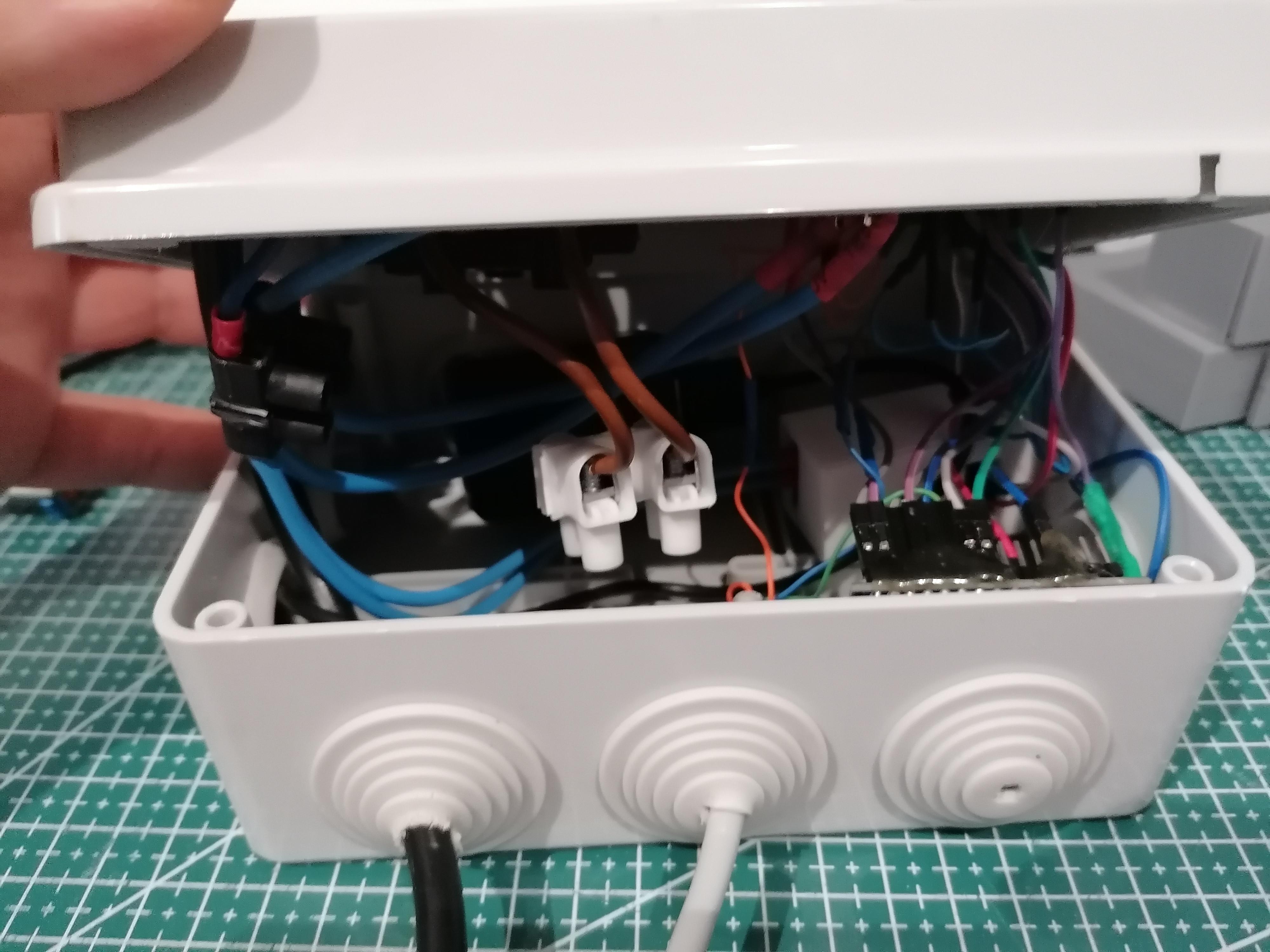
Once you tested the circuit with TEST values, you can upload the sketch again with the standard values or you can modify them to better suit your needs.
As I previously said, I like to put some hot glue in my jumper connections to make sure everything stays in place once the box is closed, as you won't need to open it again (fingerscrossed :D).
Attaching the PIR to the 3D Printer
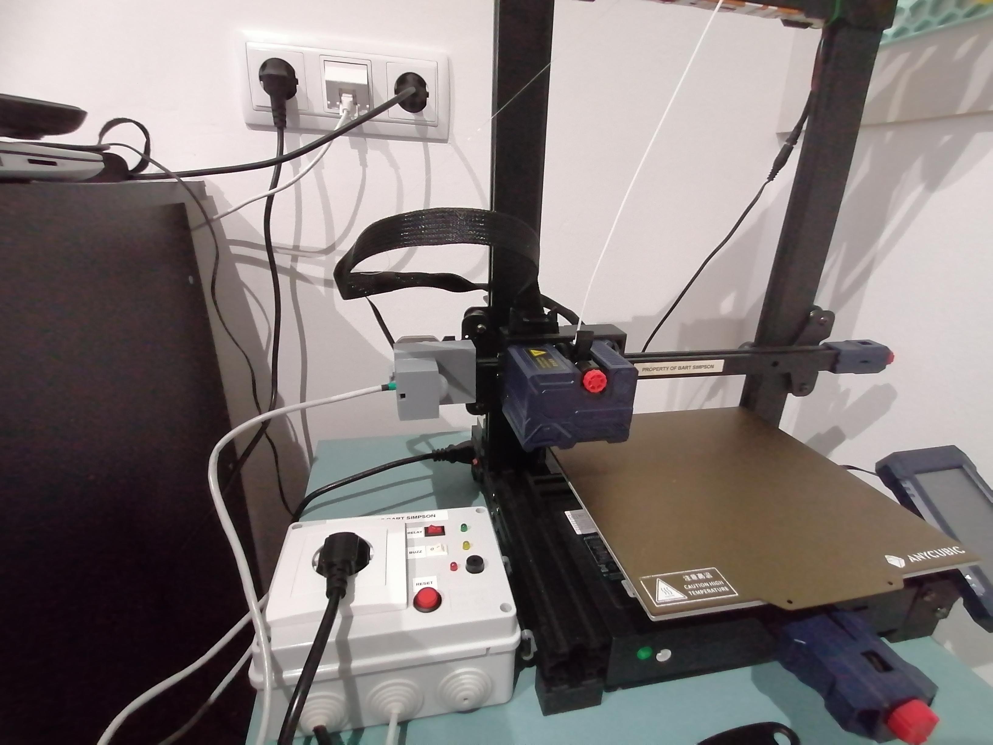
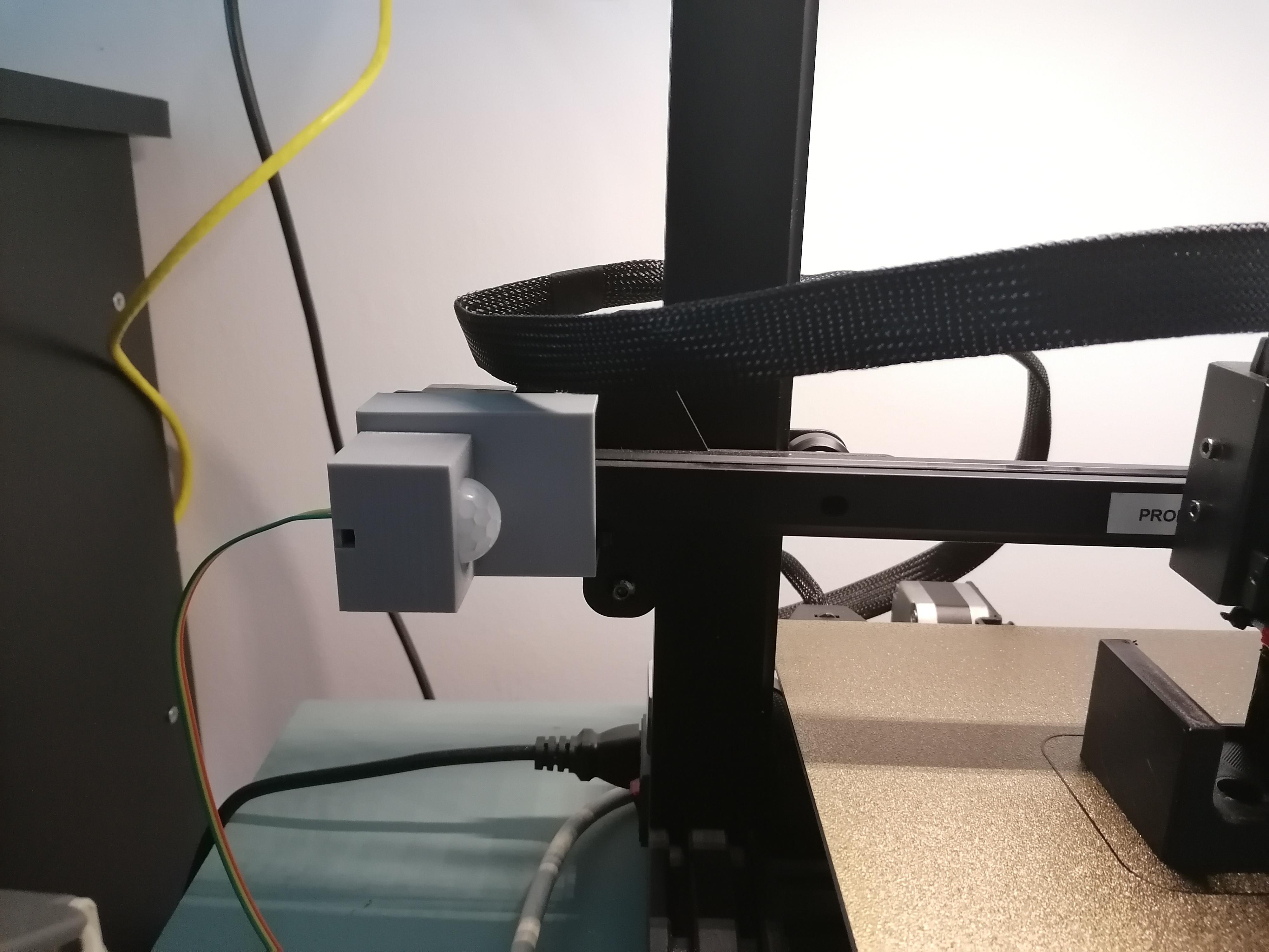
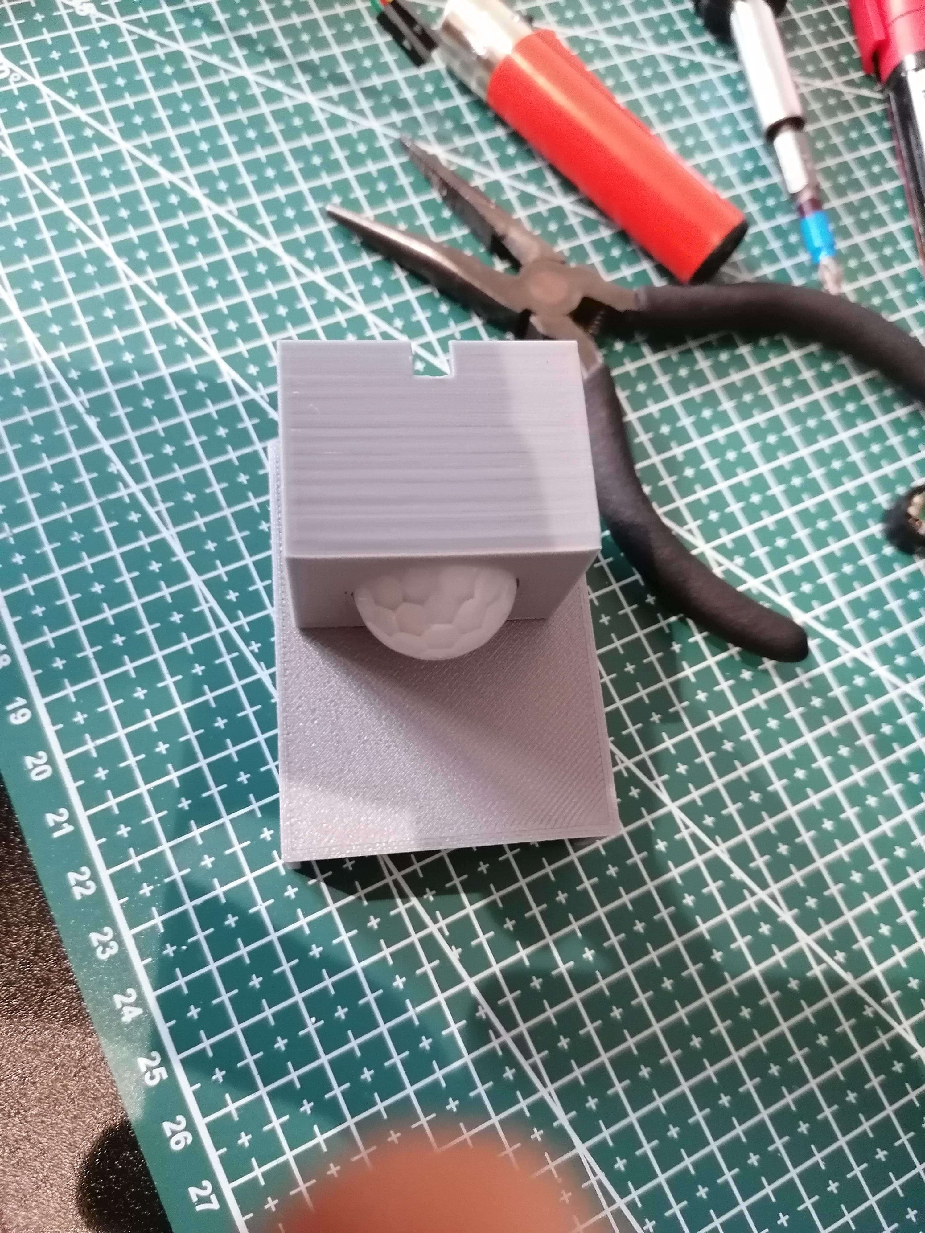
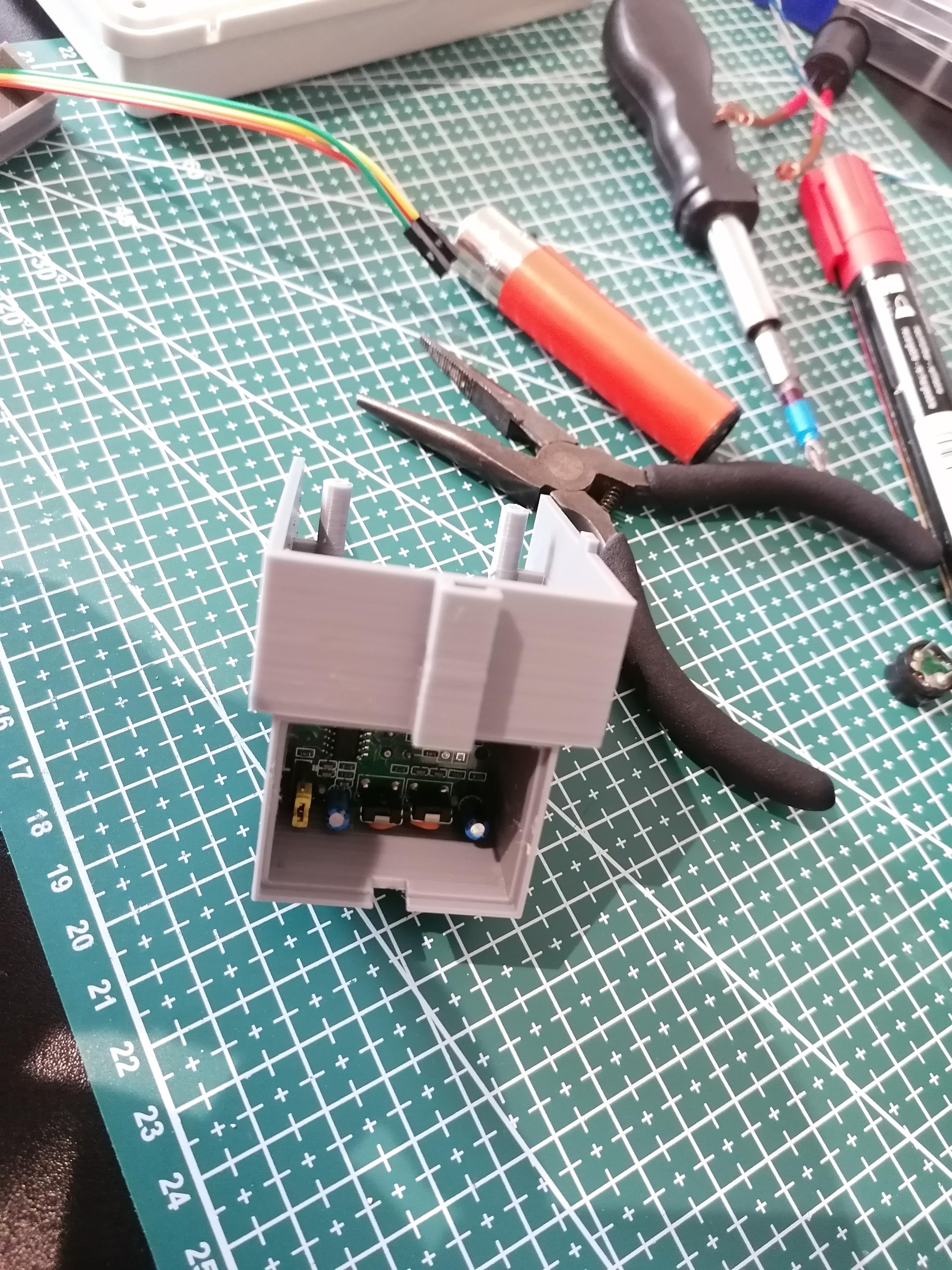
In my case I have an Anycubic Kobra, so I've printed a cover for the X Axis and glued it to a PIR Sensor case, so I didn't have to glue it to the original cover.
I'm attaching the links to both designs, hope it may help you even if you have a different printer.
PIR Sensor case: LINK
Anycubic Kobra X Axis cover: LINK
Another way would be to attaching the PIR sensor to the print head in some way but I'm pretty sure you can find a 3D printed case for your printer or design your own.
Final Test
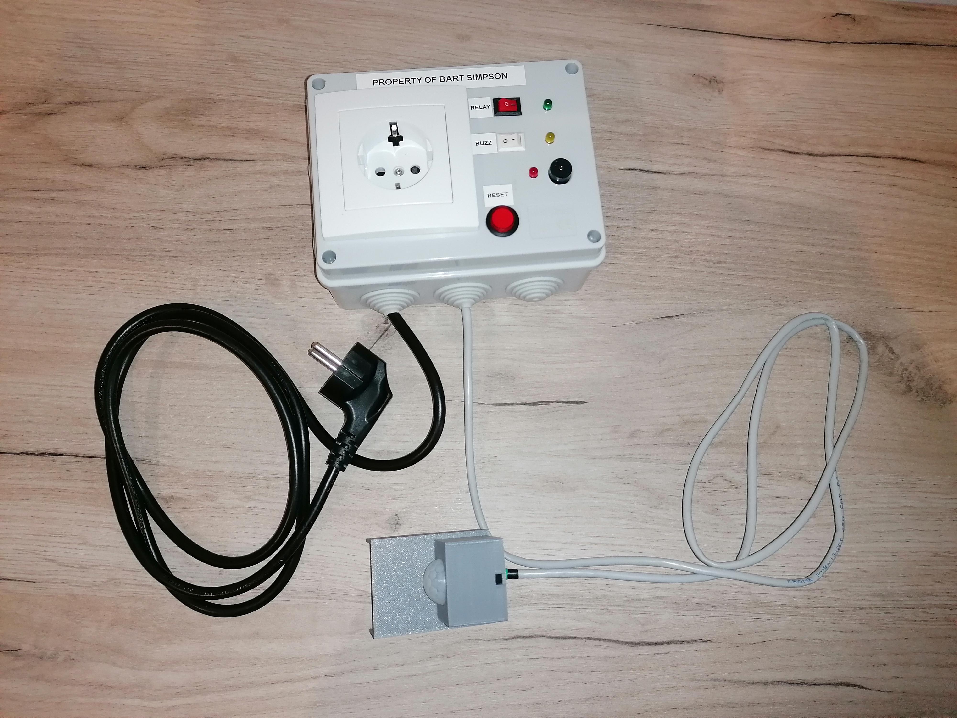
In case you've reached this step, the job is done :D
Hope you find it helpful!
Functionalities
- Relay switch: Enable or disable the switch functionality (to cut the power of the entire device) once the predefined idle time is met (programmed through the Arduino).
- Buzzer switch: Enable or disable the buzzer sound. After the predefined time specified on "TimeBuzzStart" (in the Arduino sketch) is met, the buzzer will sound during the specified duration on "TimeBuzzEnd" to alert you that the print is done. I usually disable it when I print during the night, so the buzzer will not wake me up.
- Reset the device: With the Reset button, you can restart the circuit to start the printer again.
- Programming through Arduino: There are a few parameters on the sketch I made which are meant for finetunning the setup. You'll see that I've added some comments in the code with the values I use for testing and the final values that I put when I fully test the assembly.
- "DownTimeShutdown" TEST: 30 - STD: 360 // (in seconds) maximum time allowed until relay will power everything off. I've put 6 min to ensure the printer cools down on it's own before powering it of, as the fans help on cooling. Make sure you put the amount of time you need here.
- "TimeBuzzStart" TEST: 15 - STD: 60 // (in seconds) time for the buzzer to be turned ON after no movement is detected
- "DownTimeLed" TEST: 10 - STD: 30 // (in seconds) time for the red LED to be turned ON after no movement is detected (Added this to avoid intermittent detection from the PIR sensor)