Unfold 01: Projection on Print
by cbuyukberber in Circuits > Art
21551 Views, 130 Favorites, 0 Comments
Unfold 01: Projection on Print
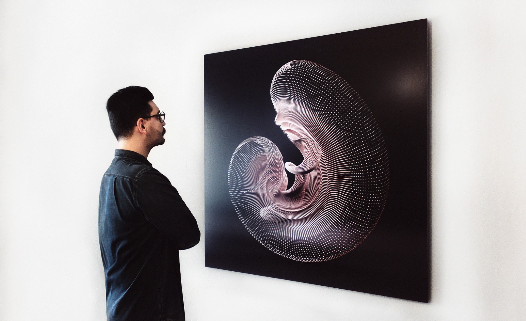
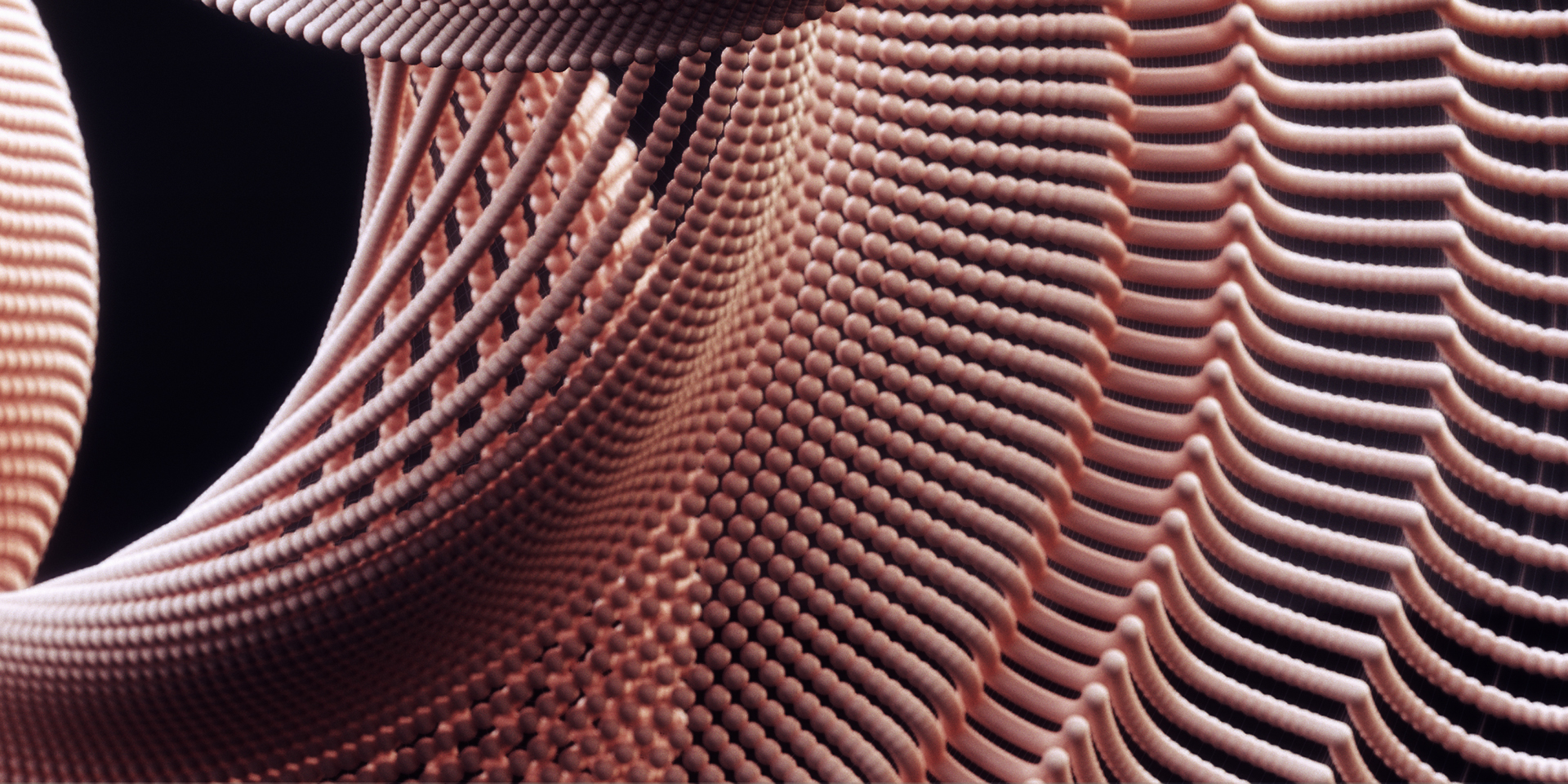

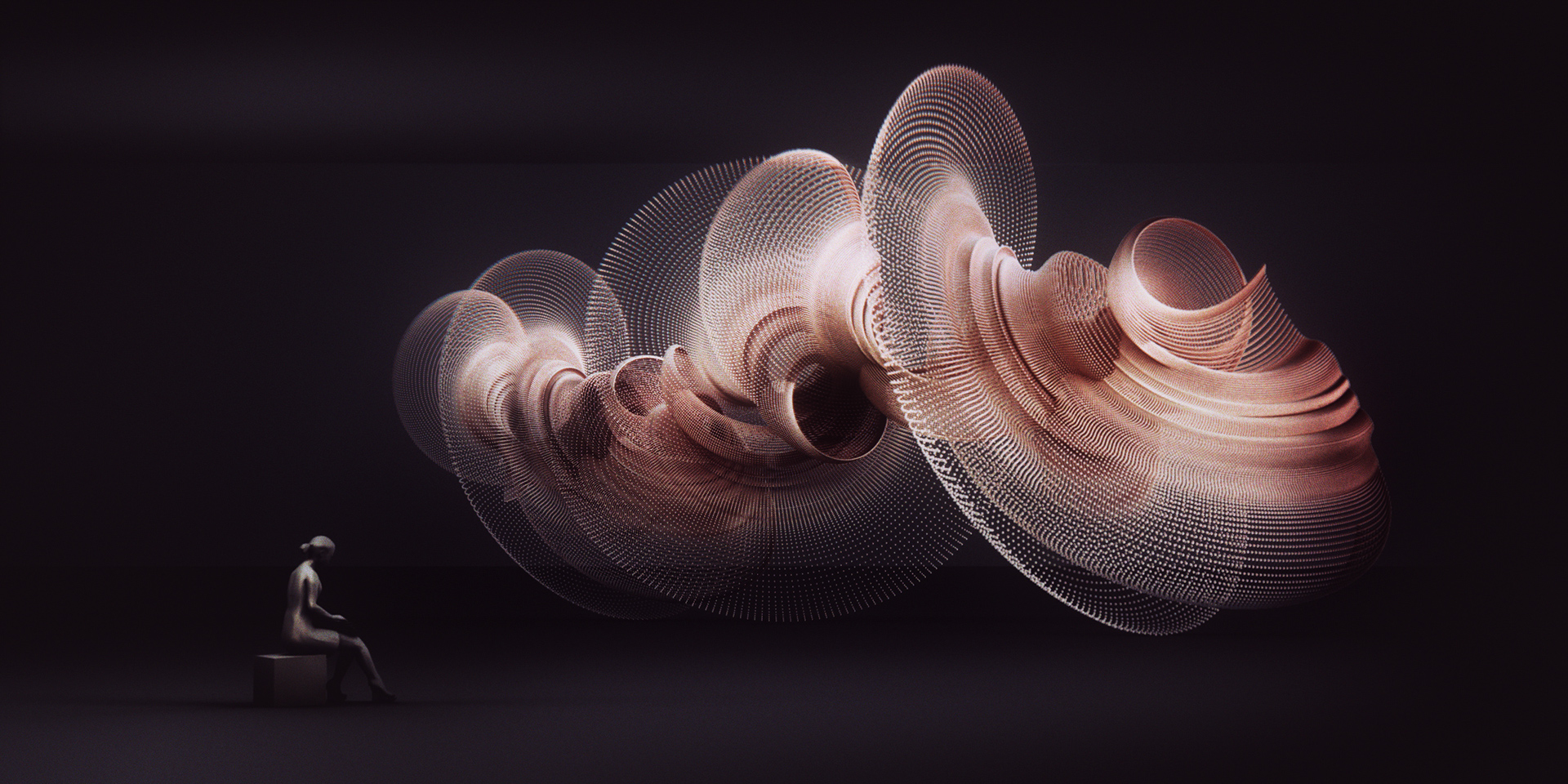
Projection on Print
120cm x 120cm Canvas + 3 Minutes A/V Loop
Digital Sculpture Studies
Unfold Series is an ongoing form experiment inspired by the phenomenon of morphogenesis (from Greek, “beginning of the shape”, the biological process that causes an organism to develop its shape). My aim with this study is to create large scale 3d printed audio/visual installations as a type of kinetic sculpture using light and sound. I created this particular version for Prizma Group Show 02 in Istanbul and experimented with light to generate a sense of depth and volume on the flat surface of printed canvas as step one, before moving to work on physical application of the form. (For the video documentation, please check out Step05)
In this post, I share all the necessary steps for the 3d modelling of the form, how to create the procedural aesthetics, rendering, creating animated content, physical print, projection mapping on the print and documentation processes. As my initial intension of this study, you may apply similar approaches to your 3d printed forms too. Let's initialize the unfolding process!
3D Modelling the Object
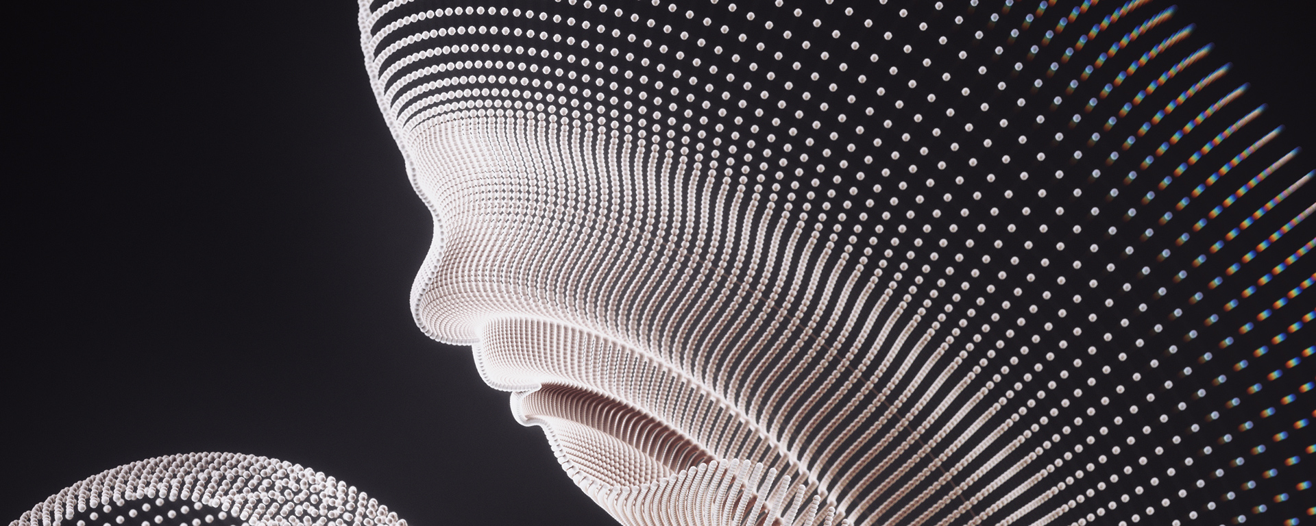
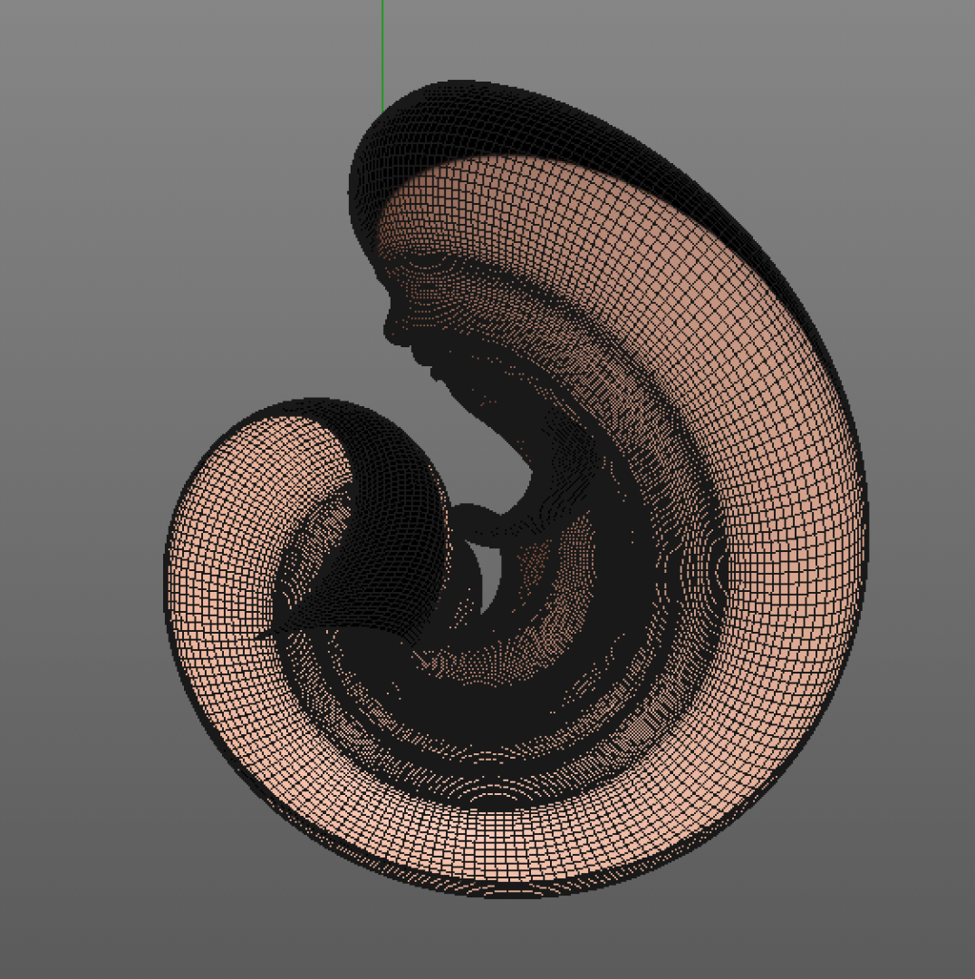
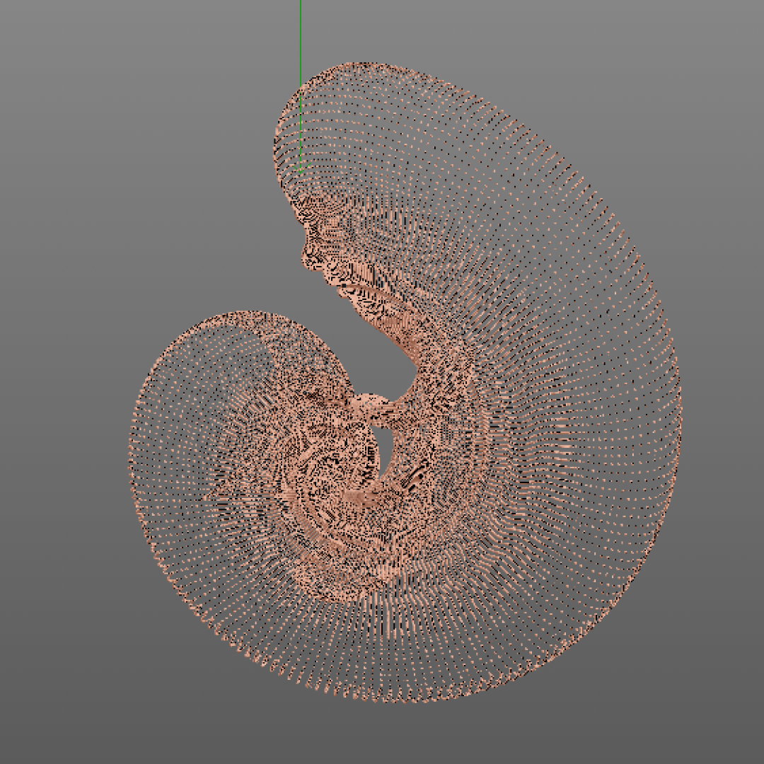
For this project, I used Maxon Cinema 4D Studio as my 3d modelling and animated content creation package. MoGraph tools are widely in use as procedural modeling and animation module in Cinema 4D that excels at making clones or copies of objects.
The organic unfolding structure basically consists of duplications of a human face in certain parameters. By using Bezier, Cloner, Loft and Atom Array tools, let's model the structure:
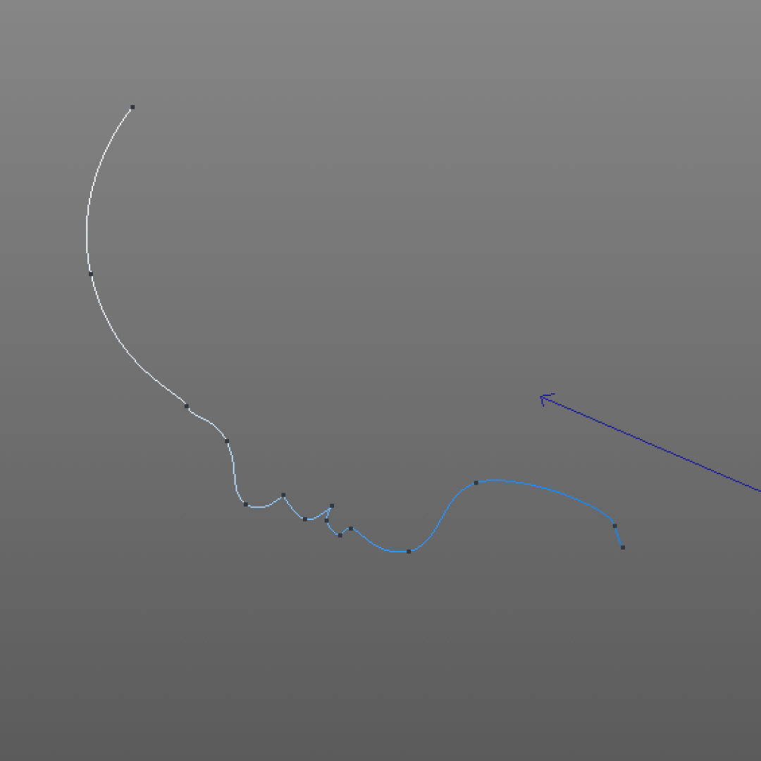
- After opening a new project (File>New), I draw a face silhouette with the bezier tool (Create>Spline>Bezier)
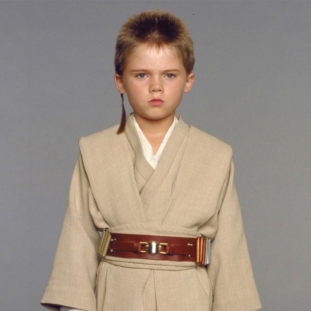
- (Trivia: I used infant Anakin Skywalker from Episode 1 as a reference for drawing)
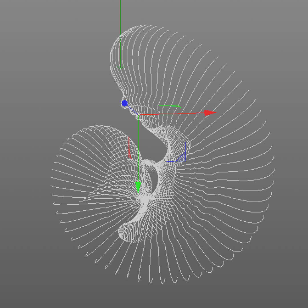
- Create a cloner object (MoGraph>Cloner) and parent it to spline we draw in the Object panel.
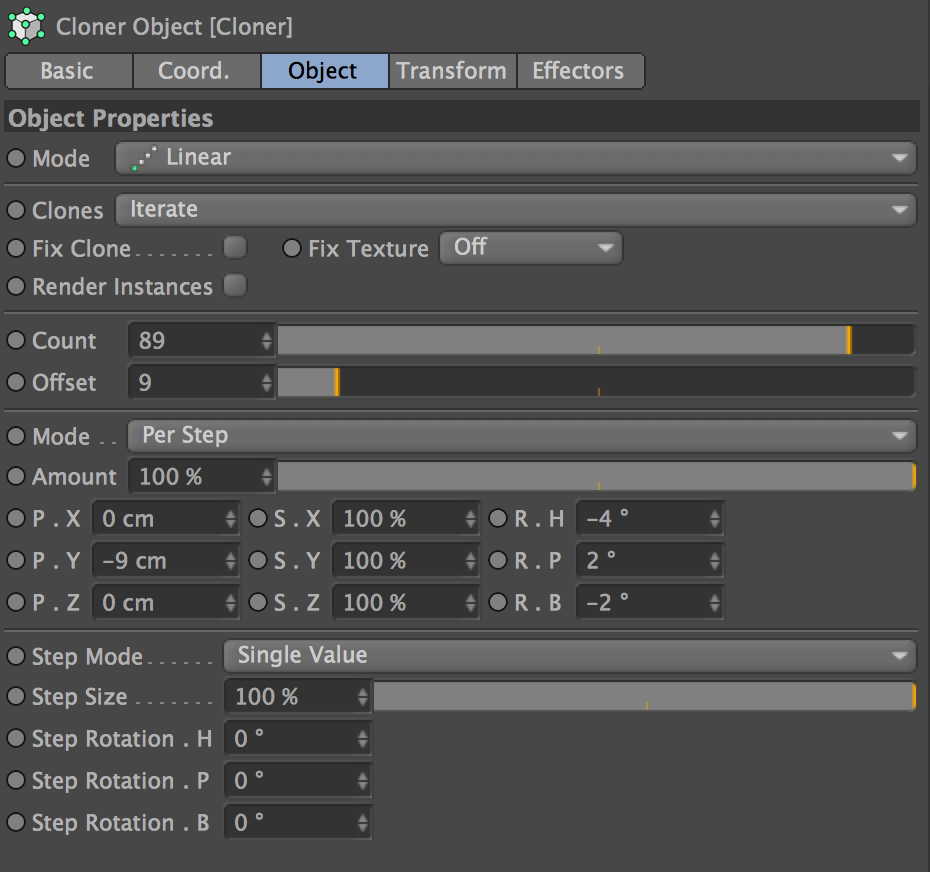
- Click on Cloner and than its Object Properties, here is the parameters I set that creates the spiral feeling.
- Mode: Linear Count: 89 Offset: 9
- P.X: 0 cm P.Y: -9 cm P.Z: 0 cm
- S.X: %100 S.Y:%100 S.Z: %100
- R.X: -4 ° R.Y: 2 ° R.Z: -2 °
- After cloning, it should look like IMG.04. Now let's create the surface over these splines with Loft (Create>Generate>Loft). Set your spline as child to Loft object. Change subdivision level with the parameters below for higher segment count which helps achieving the complexity level we want. Almost there!
- Mesh Subdivision U: 230 | Mesh Subdivision V: 3 | Isoparm Subdivision U: 3
- Now we arrive to the magical step: Atom Array (Create>Modeling>Atom Array). This command creates a wireframe look, which generates little spheres around each vertex and connects them with cylinders. Given enough spheres, the biological look will emerge.
- Cylinder Radius: 0.01 cm | Sphere Radius: 1.07 cm | Subdivision: 12
- We will prepare the form for rendering and printing in Step 02
Rendering and Preparing the Print
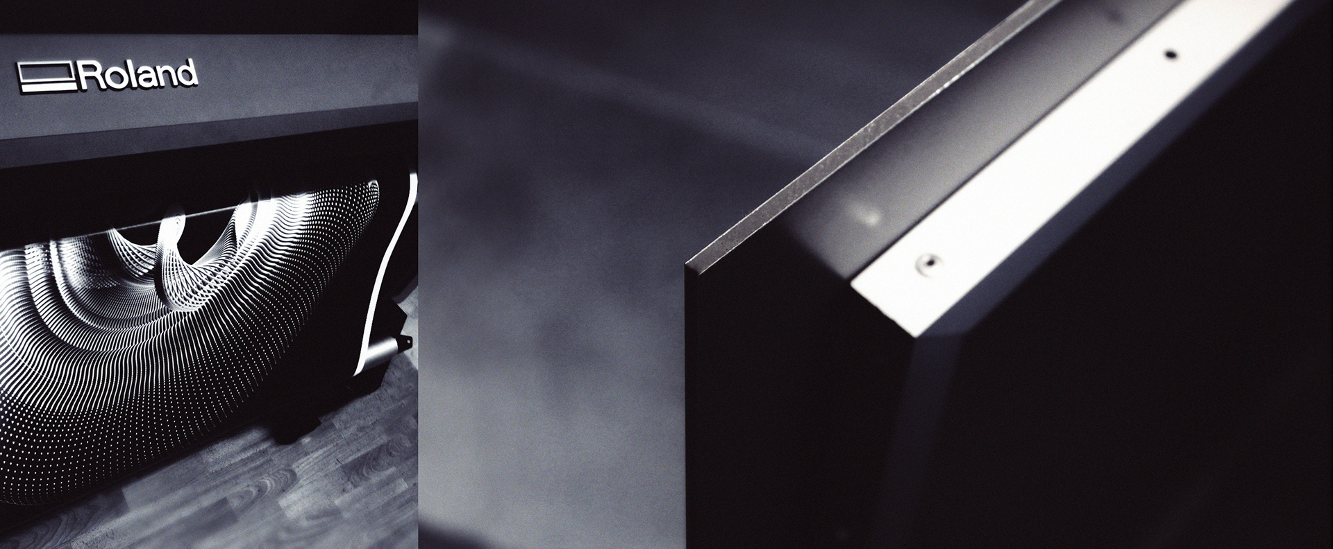
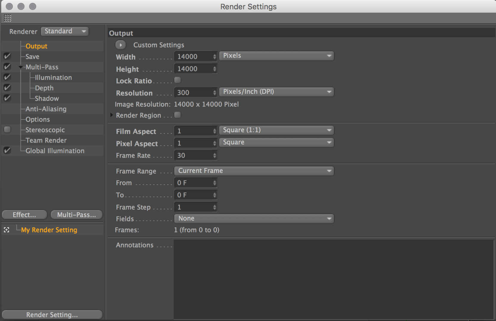
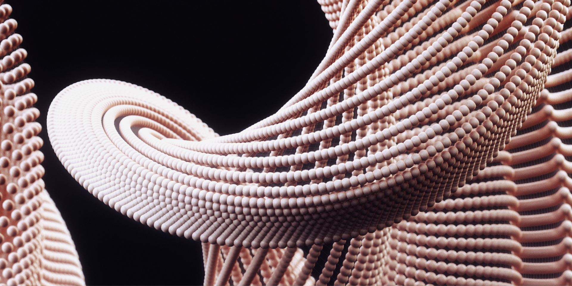
A large scale print requires a large rendering which extends the rendering time. In this project, for a 120*120 centimeters print, I set the render settings to 14.000 by 14.000 pixels with Global Illumination and Multi-Passes of Illumination, Depth and Shadow. We will use these different passes in order to achieve a photorealistic look by compositing.
Here is a couple hints for this process:
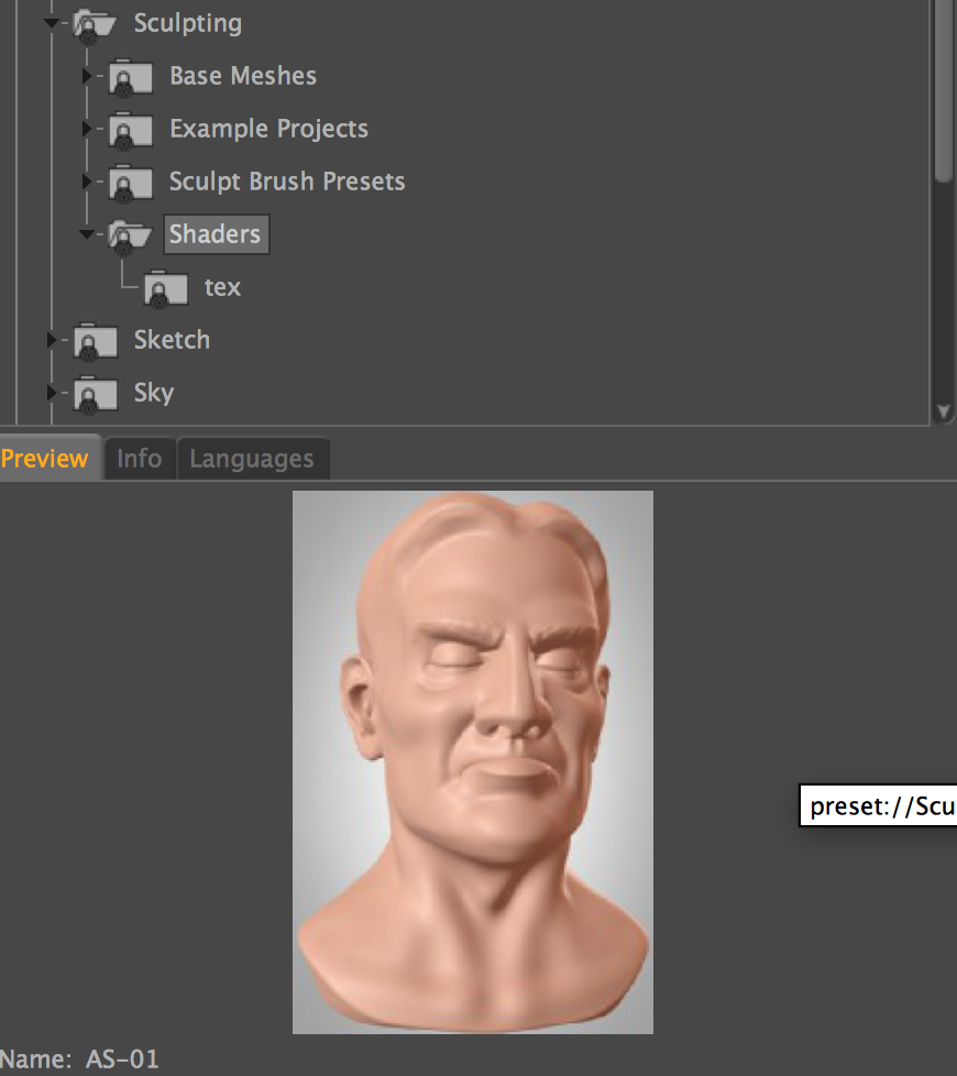
- I used AS-01 sculpting shader which is available in C4D Studio version. (Window>Content Browser>Sculpting>Shaders)
- For the lighting, check out GreyScaleGorilla, Light Kit Pro tutorials here. I used LargeProductStudio.c4d
- The large resolution renderings may take many hours. There are several online render farm services out there, which uploads your project file to their servers with a simple plugin and instead of waiting for 20 hours, you can download the result in minutes with the help of thousands of CPUs. For this particular project I used RebusFarm.
- After compositing the passes and giving the final look with Photoshop or any other image editing software you use, it is time for printing;
- Unfold 01 printing specs: 120cm x 120cm Matte Laminated Print is coated on 3mm Dibond Composite archival mounting with attached aluminium profile subframe.
Animated Content Creation
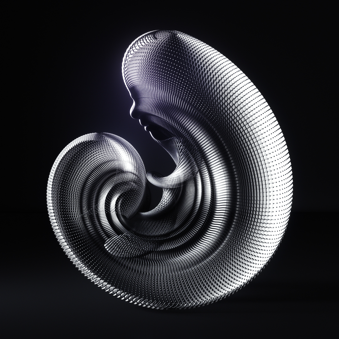
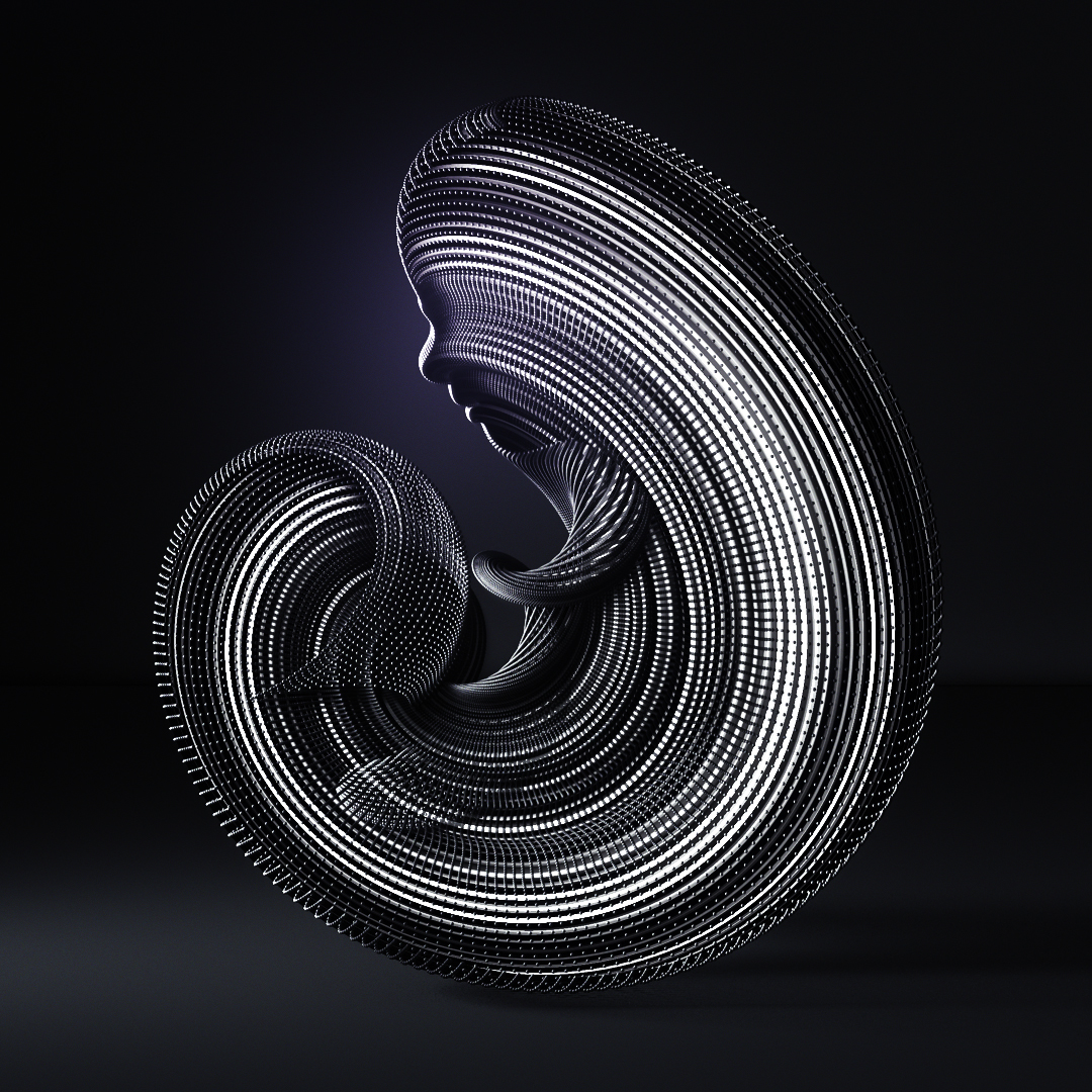
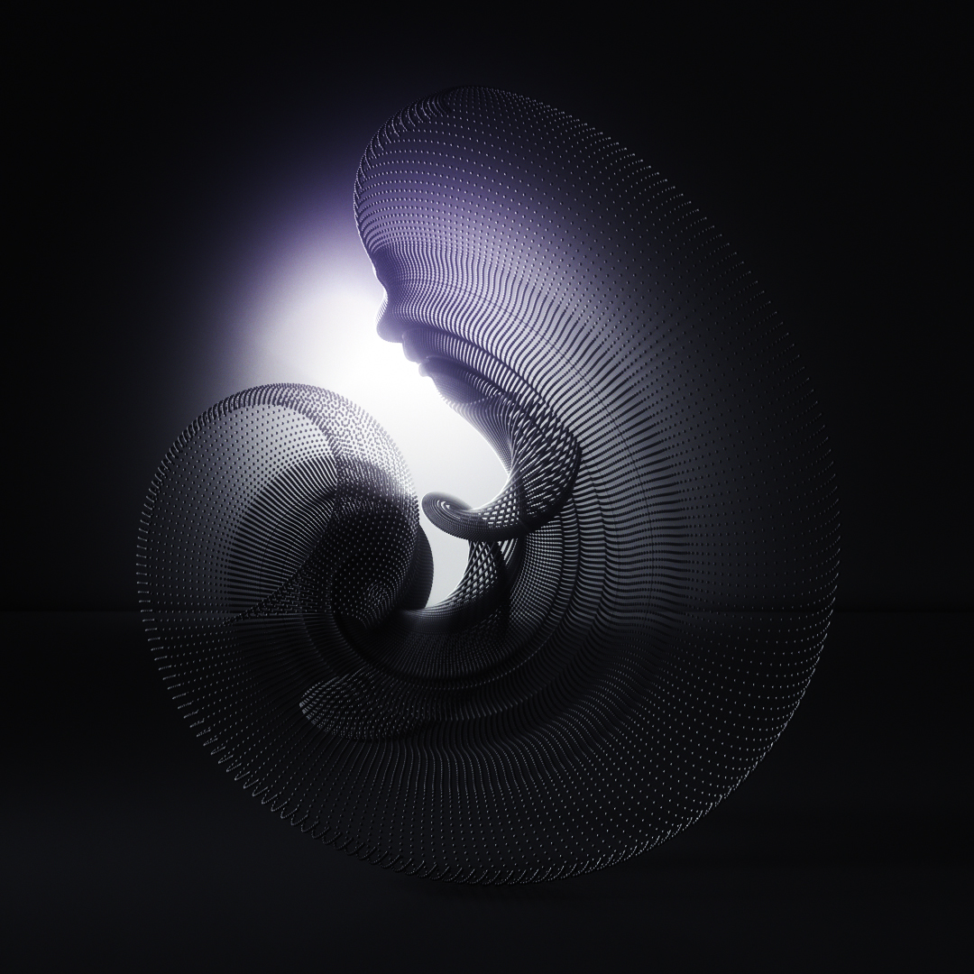
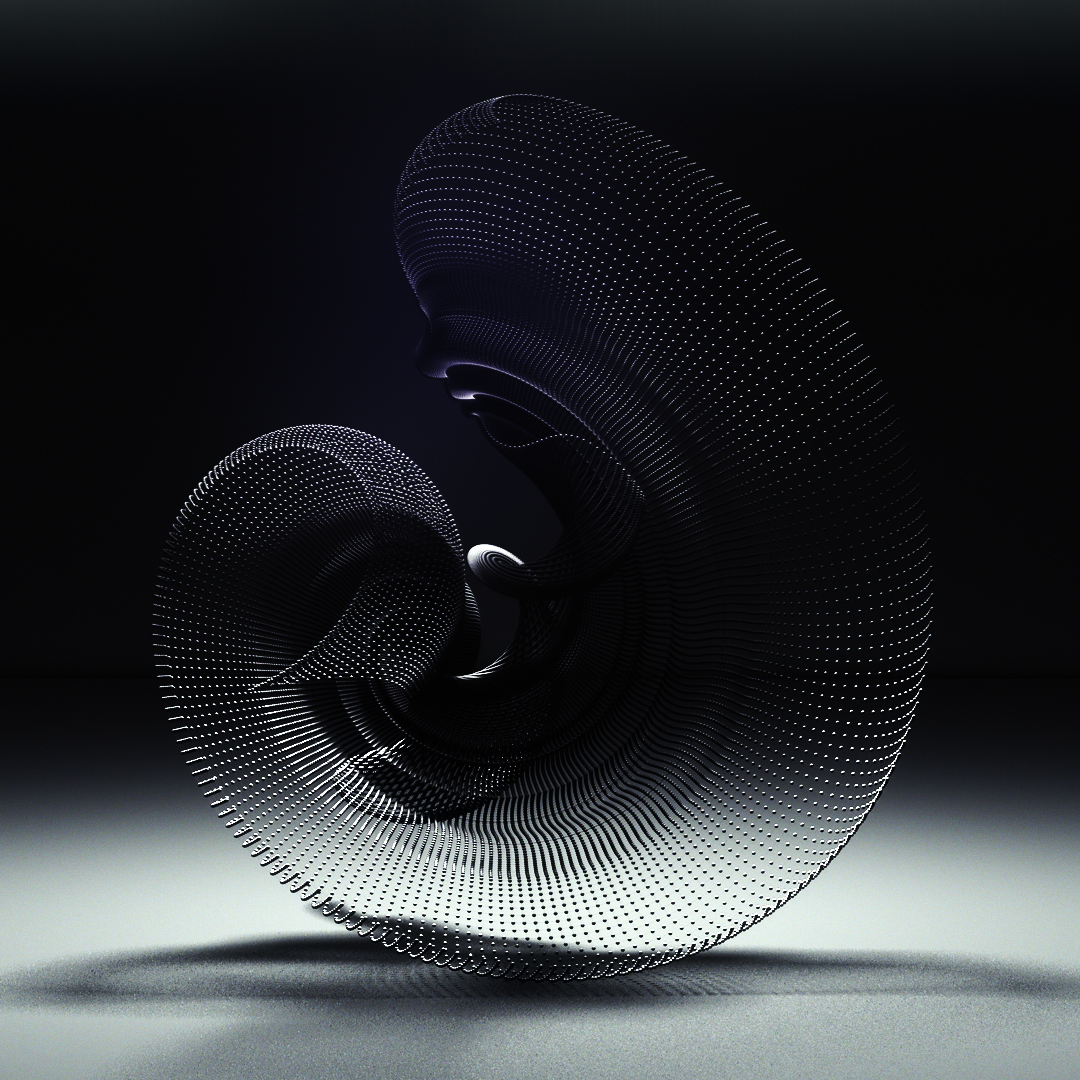
This is where the fun begins! I prepared 3 minutes of audiovisual content based on the original scene with rotating lights in different axises, animated shaders and MoGraph effectors. To minimize rendering hours, I suggest creating short loops of animations that you can repeat in longer durations later in a video editing suite such as Adobe After Effects and Premiere.
Hints:
- To animate faces on the Loft surface, turn off Atom Array, and use PolyFX (MoGraph>PolyFX) Set it as a child to Loft in the objects panel. Under transform options of PolyFX, I played with horizontal rotation parameter (R.H)
- For perfect rotating lights around the model, first I create a circle (Create>Spline>Circle) and than an Area Light (Create>Light>Area Light) Place your area light to the edge of the circle on the top view and link it to the circle in the objects panel. When you change the rotation of the circle, the light will spin with it.
- Animated shaders are fun. I used free shader pack Enhance:C4D Lite by Biomekk. EC4D - Tiles is the one I used.
Projection Mapping on the Print
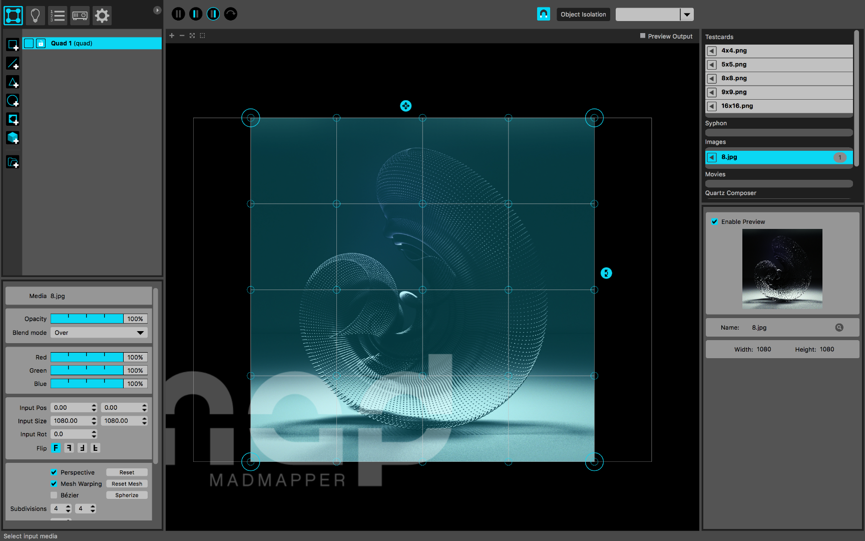
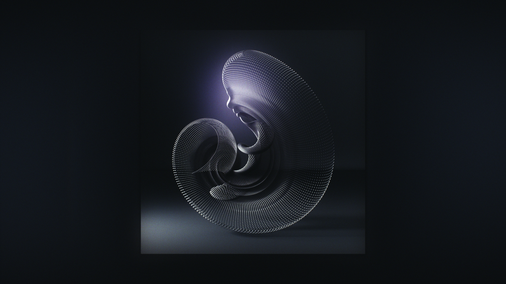
In this step we will merge our projected animation with the physical print. For this type of projection mapping processes I prefer MadMapper which is a very user friendly software that provides a simple and easy tool for video-mapping projections and LED mapping. You can download the demo version for Mac here and detailed tutorials about the features of MadMapper are here.
- As the first step of mapping process, you need to use a projector as a secondary display for your computer and enter fullscreen mode (Output>Fullscreen)
- Add a quad (square+ symbol, top left) and import your video footage (File>Import Media, preferably in h264 format)
- When your quad is selected, double click to the footage that you imported on the Testcards menu (top right) and hit play!
- Even on a 2d surface, 4 corner pin mapping may not be enough for a precise result. By enabling mesh warping on the lower left menu, you may add many subdivisions which give the full control on your projected image to match the exact coordinates with the print.
- Do not give up! Try different settings with mesh warping, move your quad in the preview panel or even make little adjustments with the projector; Eventually virtual and physical realities will match!
Final Documentation
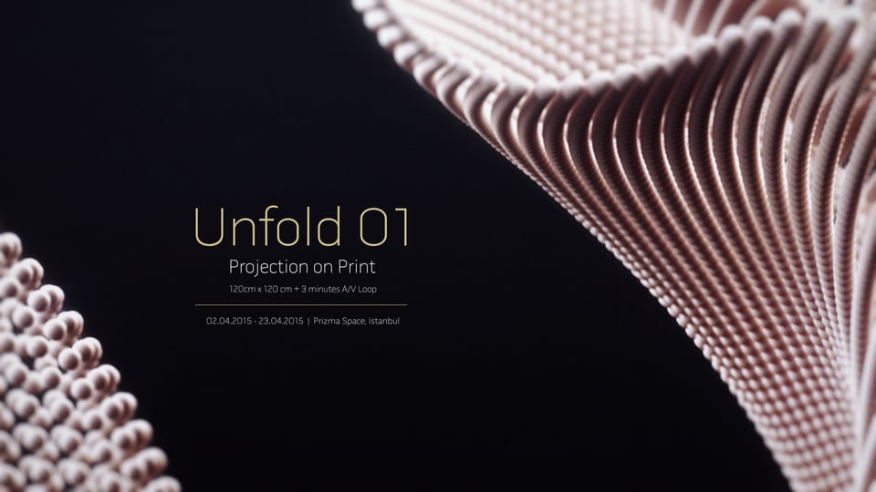
Here is the final video documentation I've prepared for the project. It is really hard to cover every single step for the beginners but I hope you find the tips and suggestions helpful and the general overview can be encouraging for creating your own projection mapping projects. Please do not hesitate to ask if you need any help during the steps and do not forget to document your own projects too!
Thanks for keeping up this far and good luck!
-Can Buyukberber