Undercover Art: a LittleBits Home Security Project
by littleBits in Circuits > Gadgets
2899 Views, 13 Favorites, 0 Comments
Undercover Art: a LittleBits Home Security Project
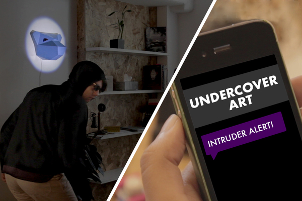
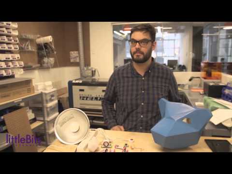
Use littleBits to turn a work of art into a modern home security device.
This mask hangs on the wall, lit by a spotlight from across the room. Whenever someone steps in between the mask and the spotlight, it causes a light sensor to trigger the threshold, which sends signals to the cloudBit, the IR Transmitter, and the mp3 player. The cloudBit sends you a text message, alerting you of the intruder. The IR transmitter turns on all the lights in the room and the mp3 plays an alarm or warning of your choosing, scaring the intruder away. We made the mask by out of paper, using a pattern we created on Pepakura Designer, software that helps you design folded paper objects. If you want to design your own mask, check out the Pepakura software page (link) as well as this super helpful tutorial from Instructables user krummrey (linkPrint out the mask pattern and cut out each of the shapes. Assembling the mask is much easier when you are using stiff paper, so we recommend printing it out on card stock or another heavy paper.)
Cutting Out the Pattern
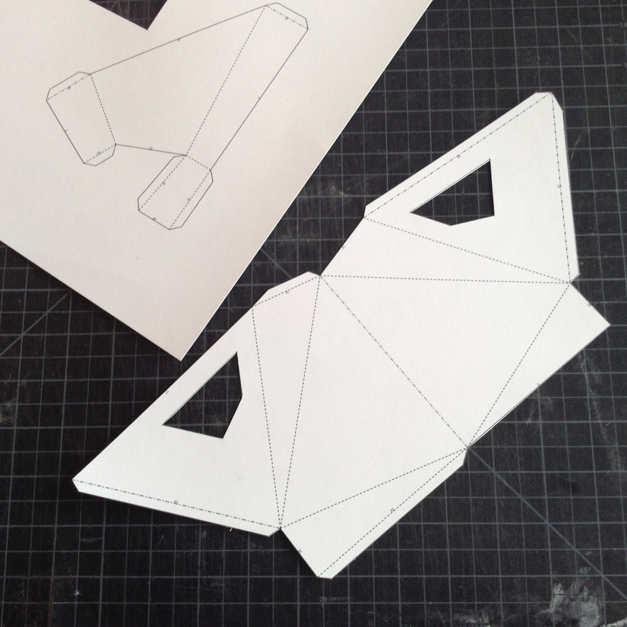
Print out the mask pattern and cut out each of the shapes. Assembling the mask is much easier when you are using stiff paper, so we recommend printing it out on card stock or another heavy paper.
Downloads
Cutting, Scoring, Folding
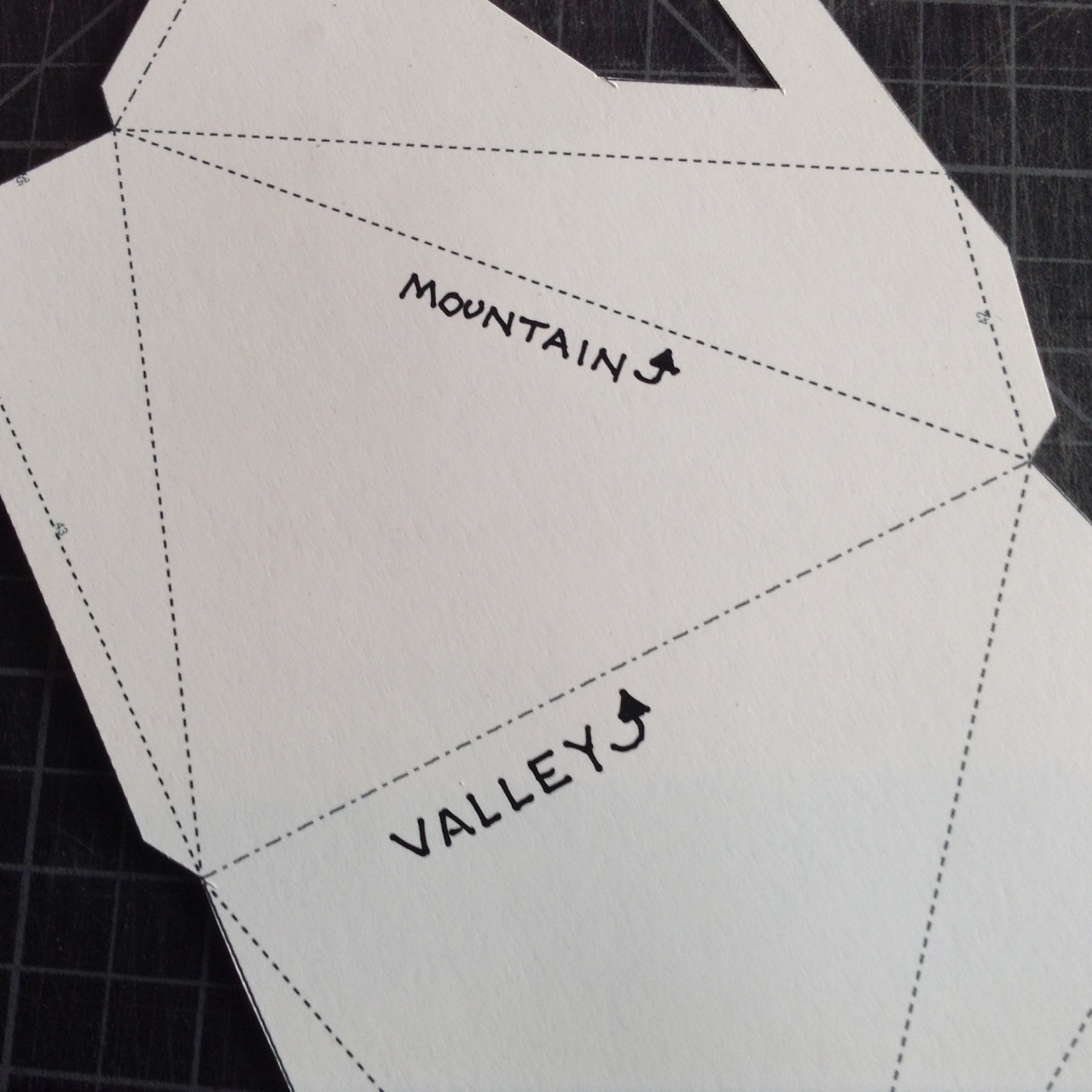
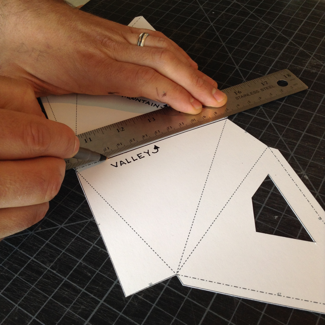
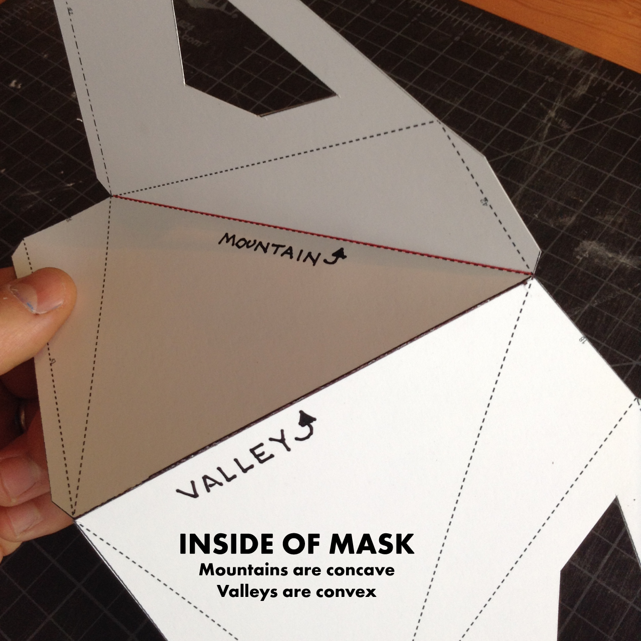
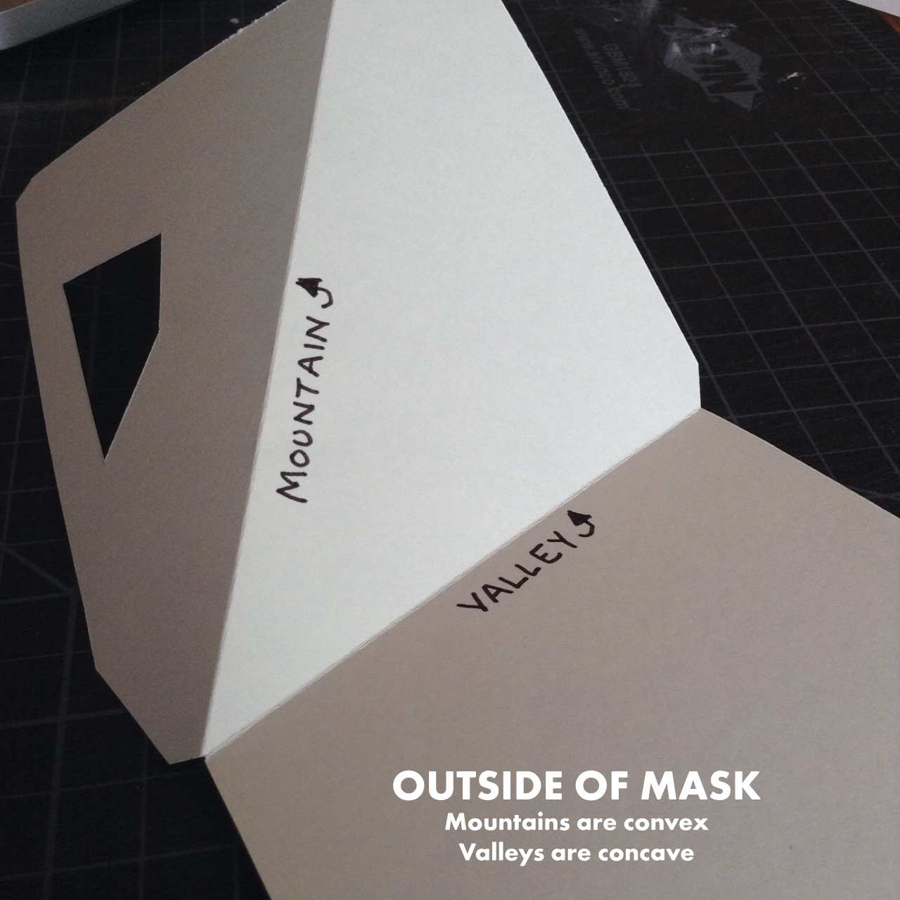
Once you have cut out your shapes, it’s time to score all those dotted lines. Scoring the lines helps make each fold crisp and straight. To score the lines, we put a ruler along each line and drew on top of each line using firm pressure on a ball point pen (use a bone folder or a very dull knife if you don’t want to mark up your paper). Pepakura models have two types of dotted lines. Long dashes are mountain folds, meaning the fold will form a convex point on the outside of the model (like a mountain). Alternating long and short dashes are valley folds, meaning the fold will form a concave point on the outside of the model (like a valley). If you are using a ballpoint pen to score your lines, having two different colors will help you tell which folds are mountains and which folds are valleys.
Glue the Mask
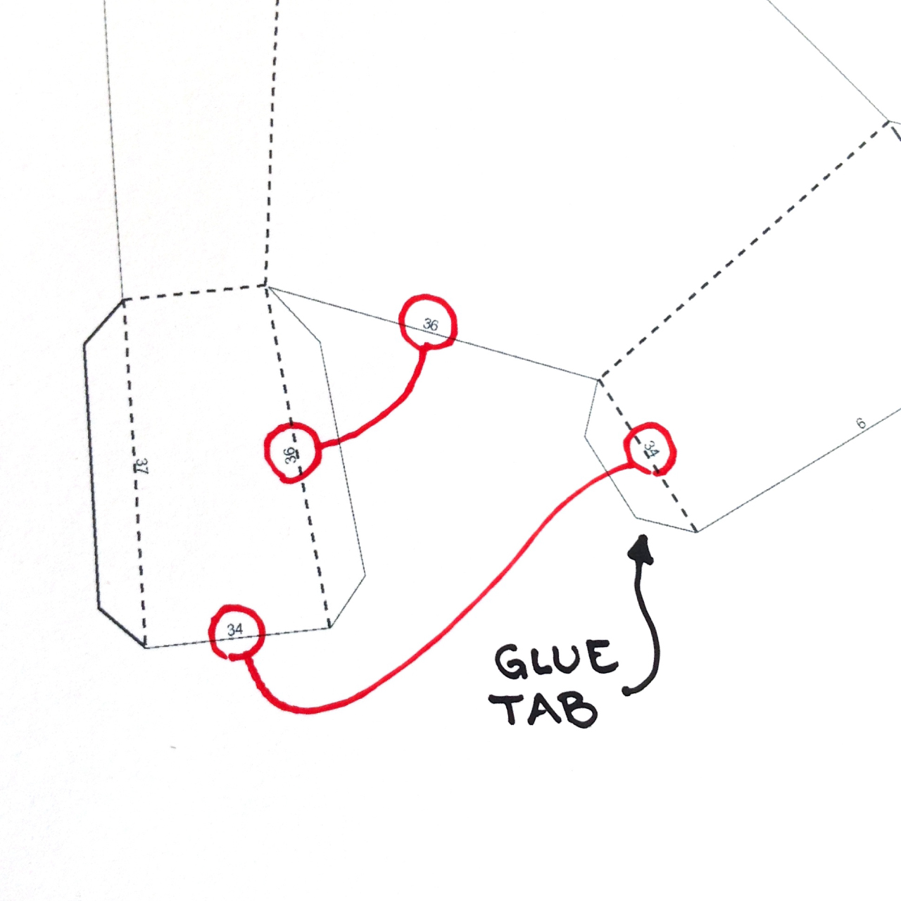
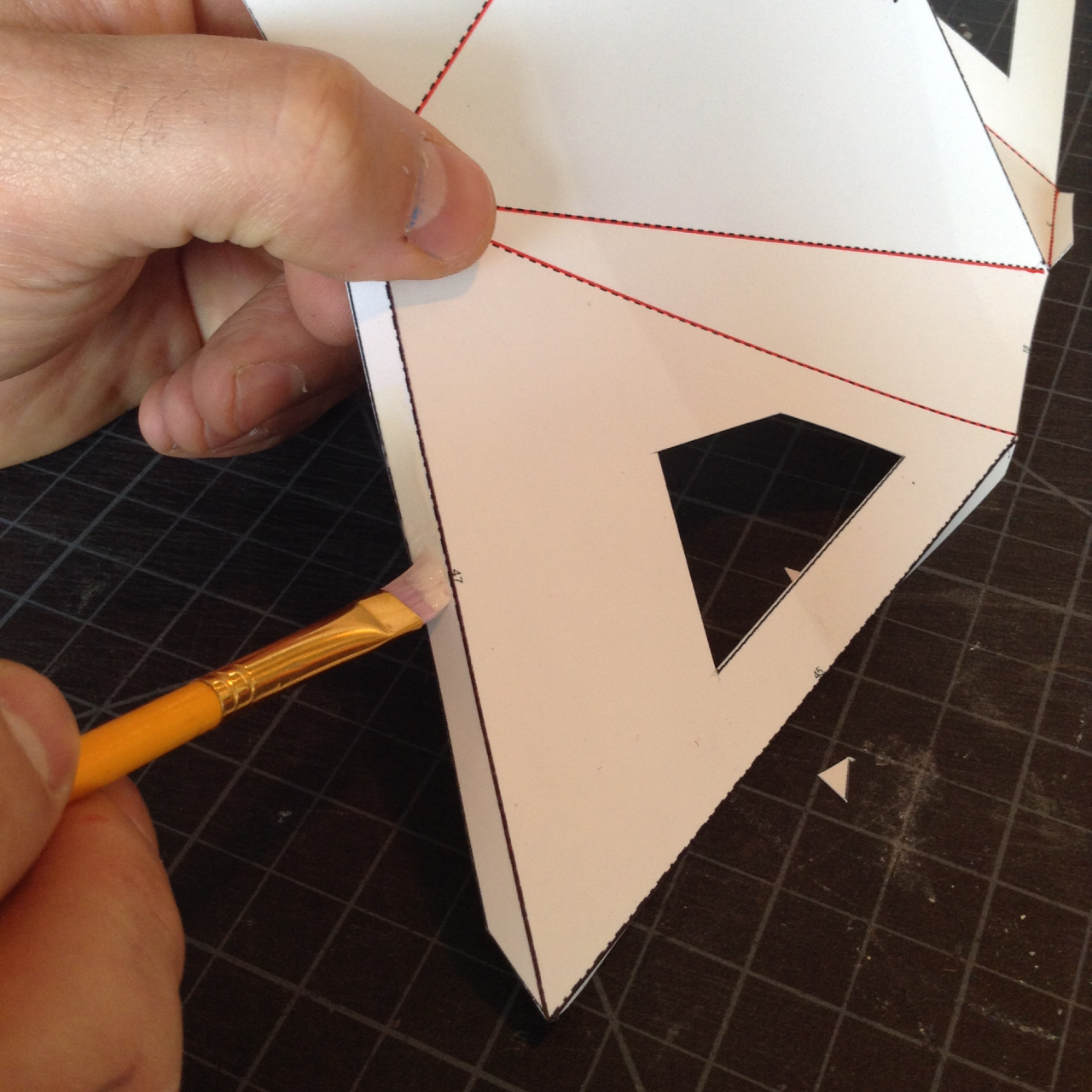
Now it’s time to glue up your mask. The edges of each shape are numbered. You can tell which edges needed to be glued together because their numbers will match. We recommend using a small brush to apply glue to each tab. The brush helps you get a thin even coat of glue. Using too much glue gets pretty messy pretty quickly (and takes much longer to dry).
Optional: Hardening the Paper Mask
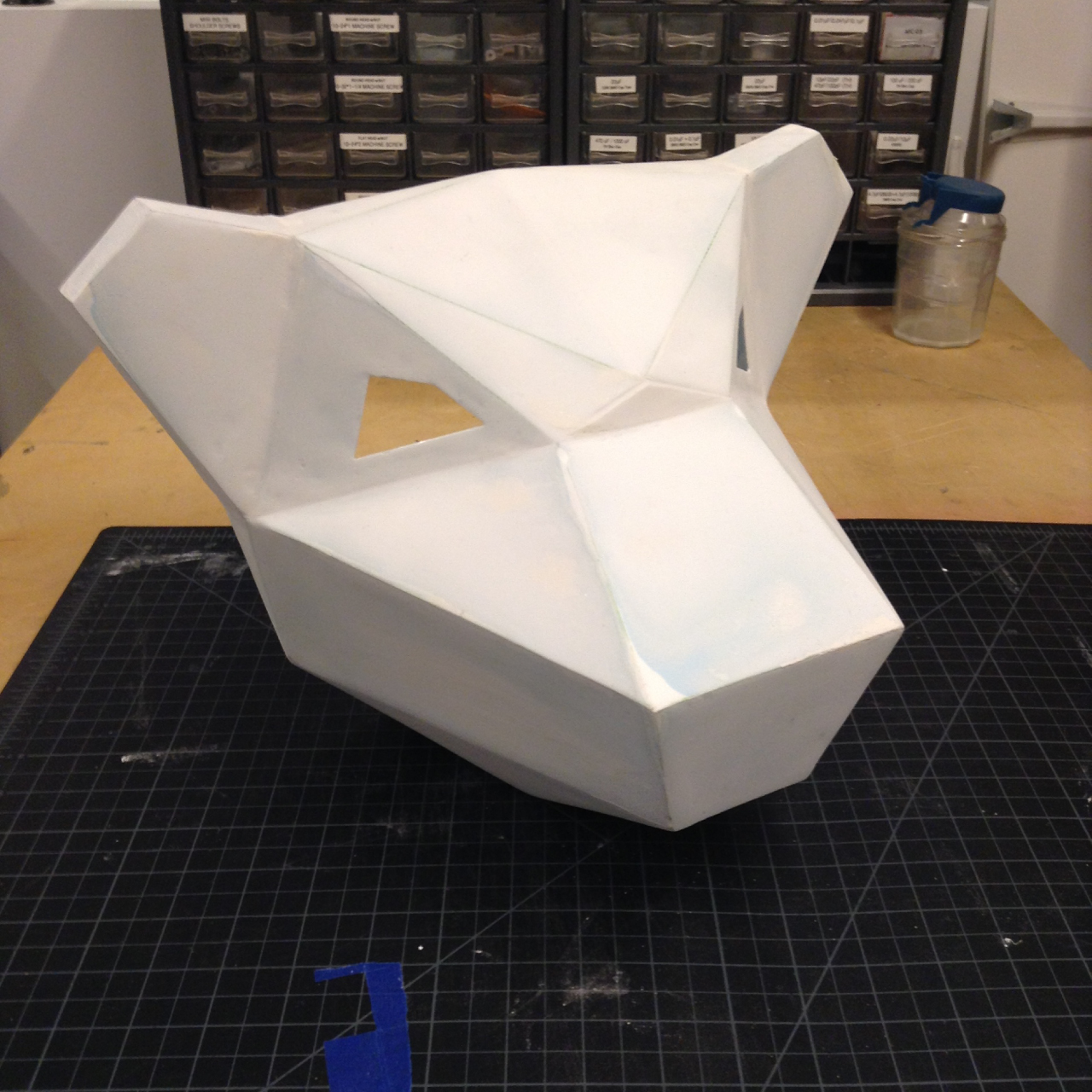
Once all the pieces were assembled and the glue had dried we decided to go a couple of steps further to make out mask more durable. However, this is totally optional so feel free to skip this step. A lot of our projects travel to various events around the country and we were worried that the paper would get crushed in shipping. There are quite a few options for making your paper models hard and durable and most of them involve spraying or brushing on some kind of resin. We used a two-part casting urethane called Smooth-On Smooth-Cast 321. We would mix about 2 ounces of resin, brush it on in a thin coat, wait for it to cure (about 30 minutes) and then add another coat. Once we were satisfied with the thickness of the resin we sanded the mask down for a smooth finish and applied a couple of coats of bright blue spray paint. NOTE: Be sure to read all the instructions for the resin and use the recommended safety equipment.
Load Sound Files on the Mp3 Module
Now we can set up our circuit. The first step is to load a sound file onto your mp3 player. This is the sound that will play when your light sensor triggers the threshold. To do this, eject the SD card (the small black card in the metal holder) from the base of the board by pressing it in. Place the SD card in the SD card adapter provided with your mp3 module, pop it into your computer, and add any .mp3 files you like. When you are done, place the SD card back in the mp3 player. Make sure it clicks in place. Once your sound files are loaded, switch your mp3 player into once mode so the alert track will play one time whenever it is triggered.
Assemble the Circuit
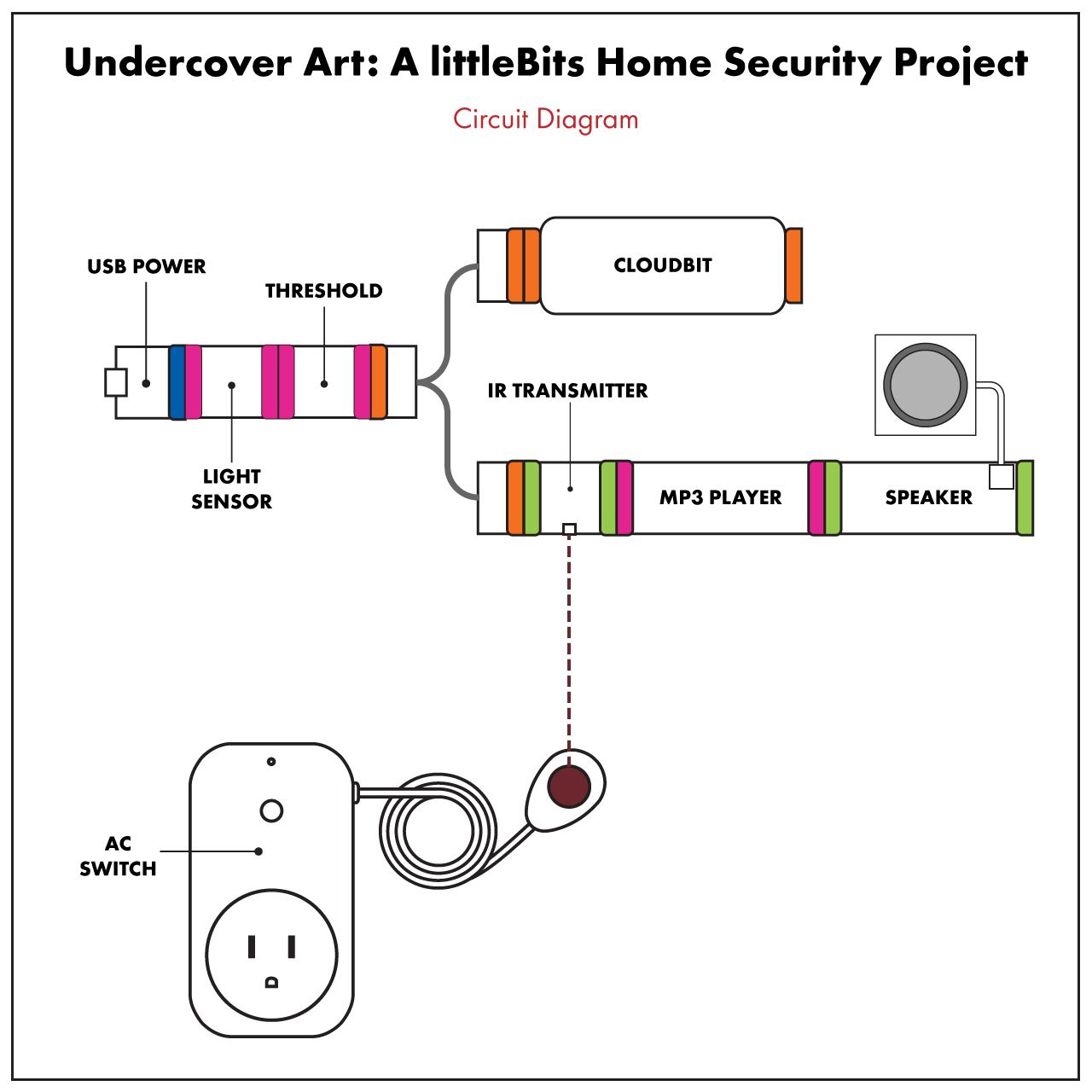
Next, assemble the circuit shown in the circuit diagram. We recommend using shoes to keep the modules together and help attach them to the mask or wall.
Place Your IR Transmitter
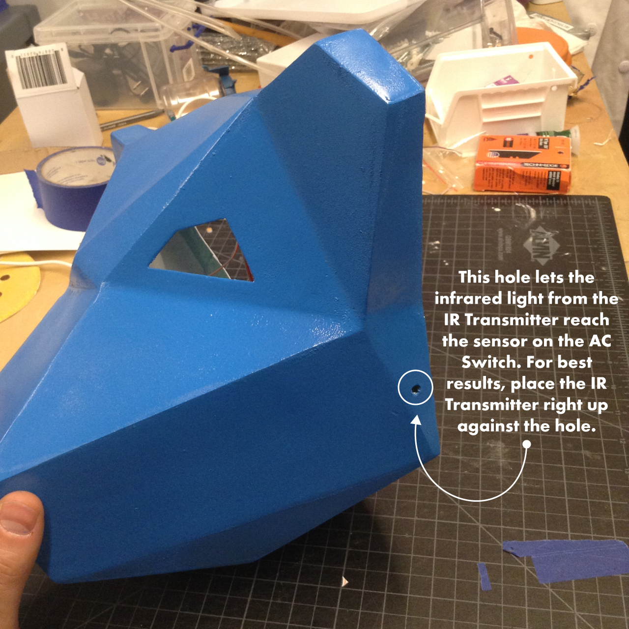
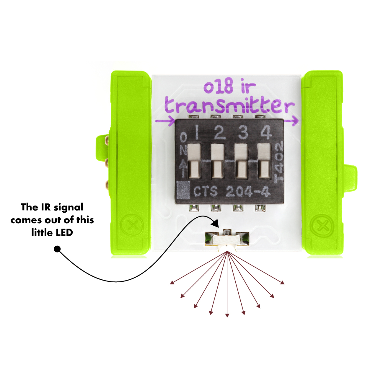
Once your circuit is assembled, cut a small hole in the mask and position the IR transmitter right against the hole. This will allow your transmitter to send its signal to the sensor on the AC switch.
Mount the Circuit and the Mask
Plug in your circuit and mount it to the wall and place the mask over it. Position the sensor of the AC switch so that it can receive signals from the IR transmitter in the mask. The IR transmitter sends out a beam of infrared light, so the AC switch sensor needs to be in the path of that light. Now place a spotlight on the other other side of the room and point it at your mask. You will want to position the spotlight and the light sensor so that the spotlight shines through the eye holes of the mask and hits the light sensor.
Adjusting the Threshold Module
Once your cloudBit has connected to the wireless network (when the light on it stops blinking and becomes a solid green) it’s time to calibrate your light sensor, threshold, and spotlight. First, make sure your light sensor is set to dark mode (this means the voltage will go up the darker it gets). Open cloud control and check the Receive tab for your cloudBit. You will want to adjust the sensitivity of the light sensor and the level of the threshold so that it’s receiving no signal when the spotlight is on the mask, but goes up to 100% when when you block the light from the spotlight.
Set Up the AC Switch
Now we need to setup the AC switch so that it recognizes the signal from the IR transmitter. To do this, plug in the AC switch and wait for the little red light on it to start blinking (this means that it is in pairing mode, and will pair with the first signal it receives). Once it is blinking, block the light from the spotlight, which will cause the IR transmitter to send it’s signal to the AC switch sensor. The light on the AC switch will blink fast a few times, then go out, letting you know the two have been paired.
Set Up Your IFTTT Recipe
The last thing we need to set up an automated text message every time the cloud get’s triggered by the light sensor. We’ll do this with a recipe on IFTTT. The recipe you set up will look like this: IF input is received on the cloudBit, THEN send us a text message.