Ultrasonic Distance Measurement Tape
by goks_lf in Circuits > Arduino
5215 Views, 41 Favorites, 0 Comments
Ultrasonic Distance Measurement Tape
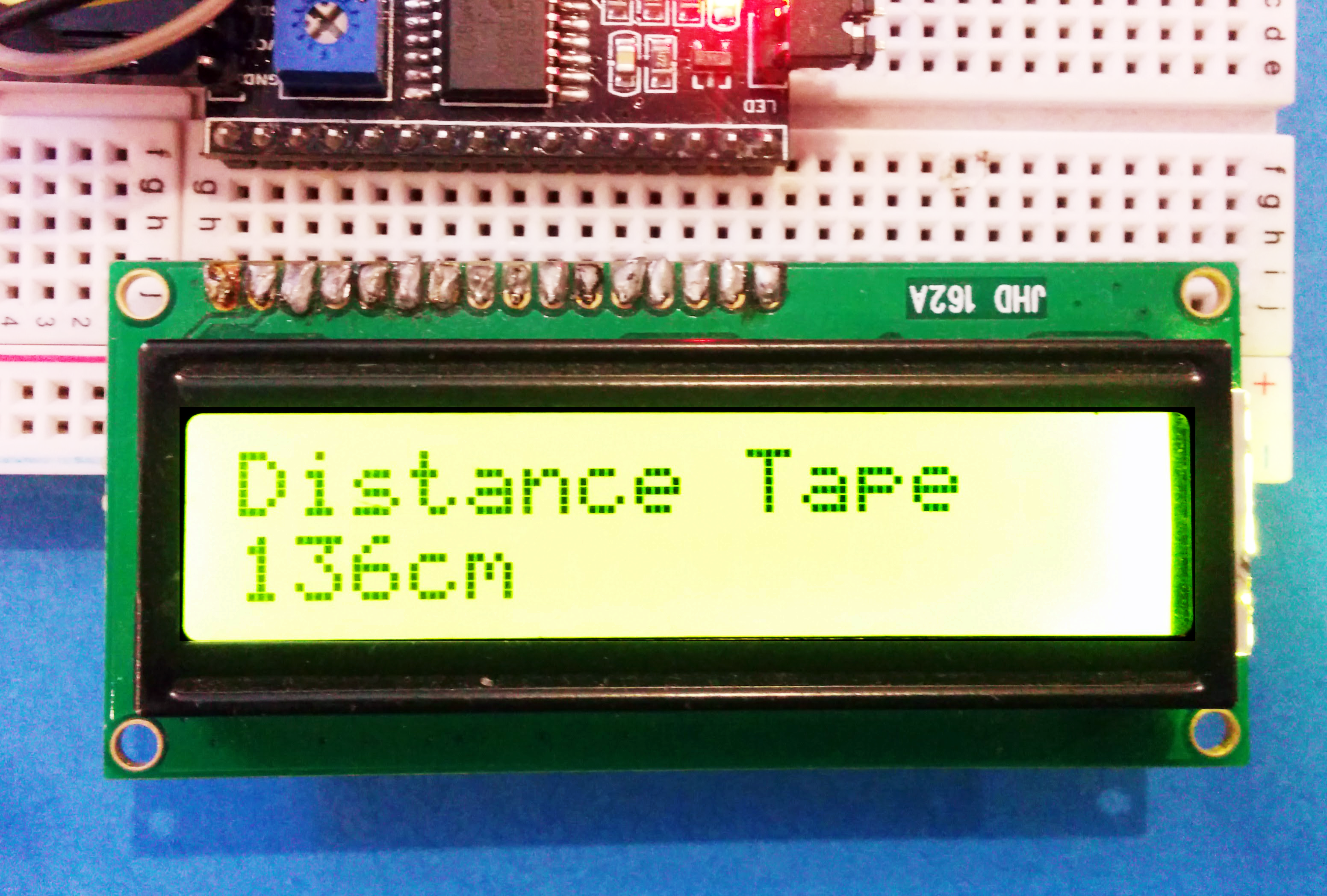
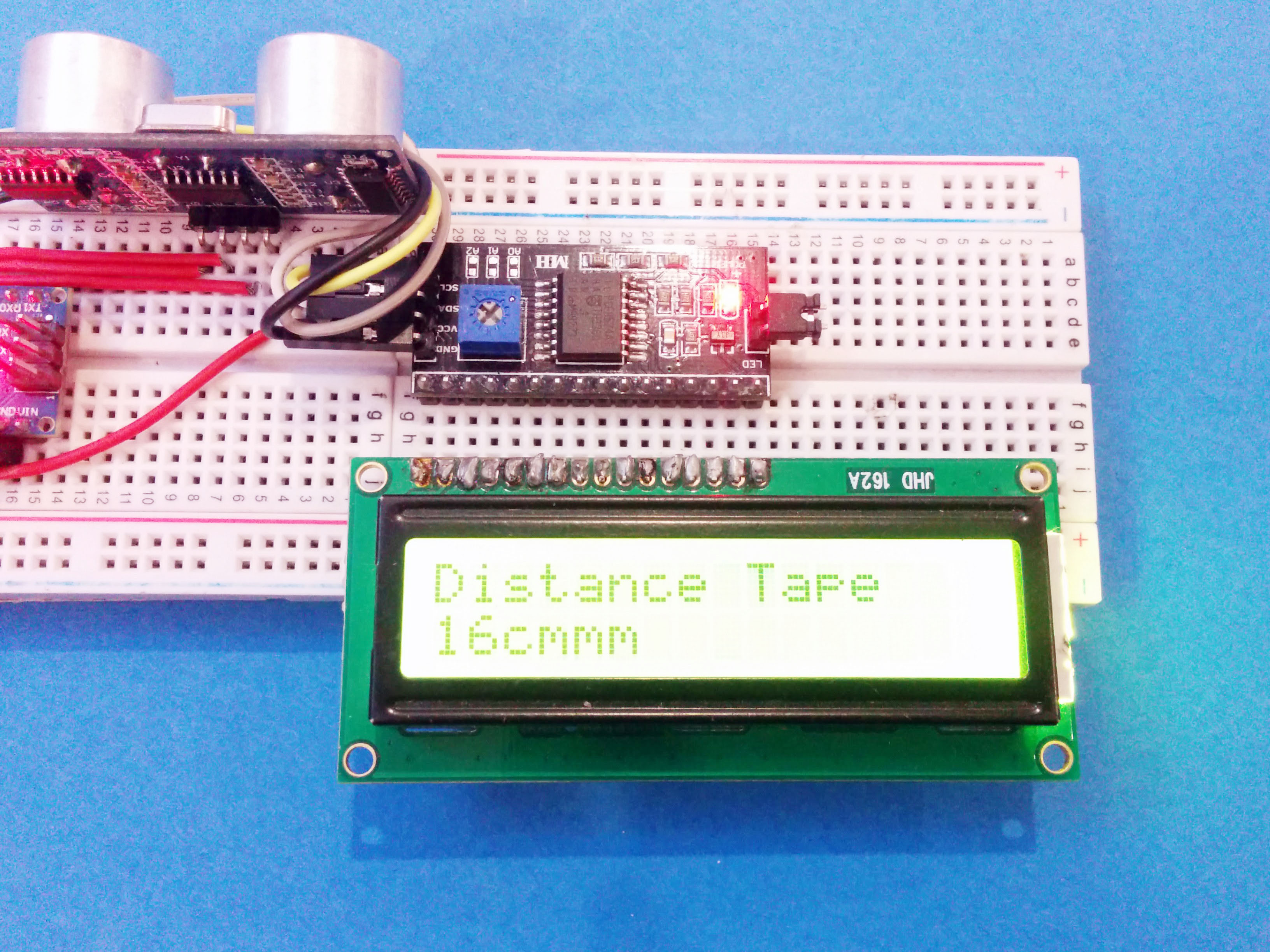
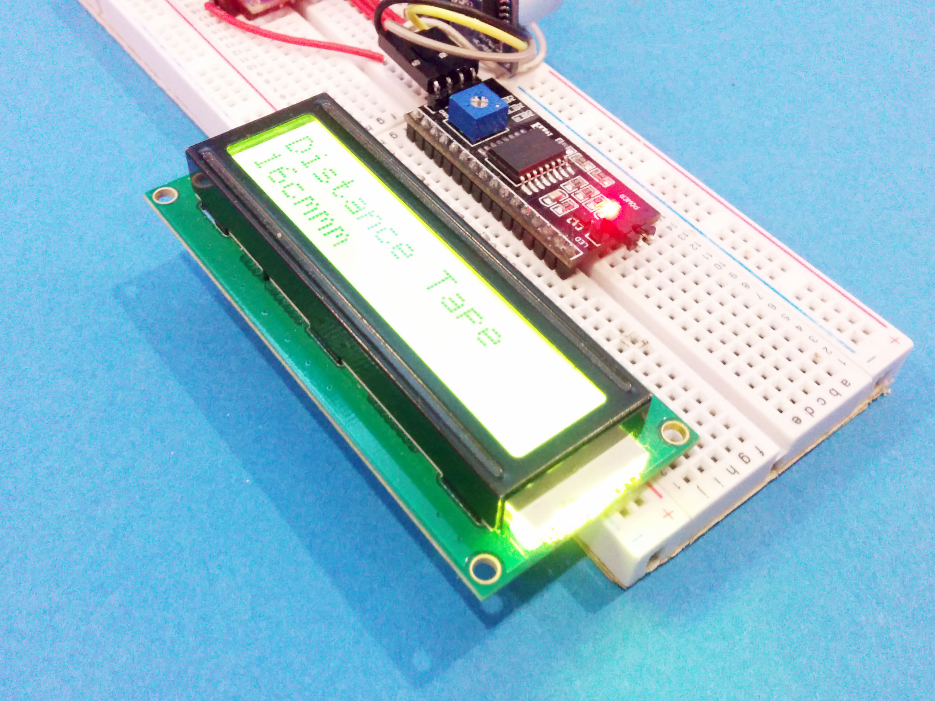
A measurement tape is an essential part of any workshop and there are tons of tapes you can select from, but there is nothing better than a DIY Project that you can use as a tool.
In this Instructable, I'll be showing you How to make an ultrasonic Distance Measuring tape using Arduino. This is an instrument which uses ultrasonic sensor (HC-SR04) to find the distance and displays it on an LCD screen. This is a simple project for which you'll need to know how to interface the components with the Arduino. For more info on that check out my previous Instructables.
Components Required
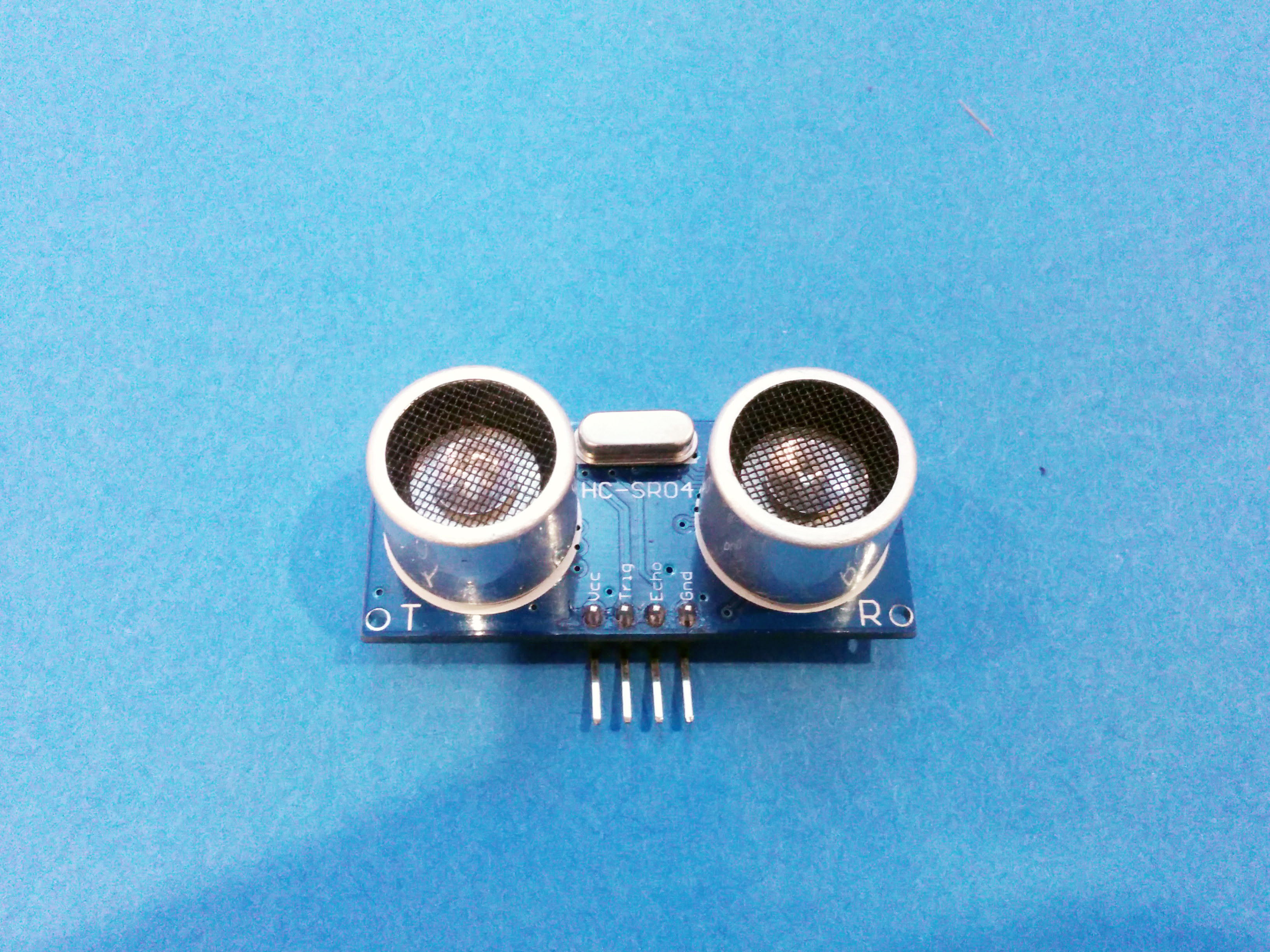
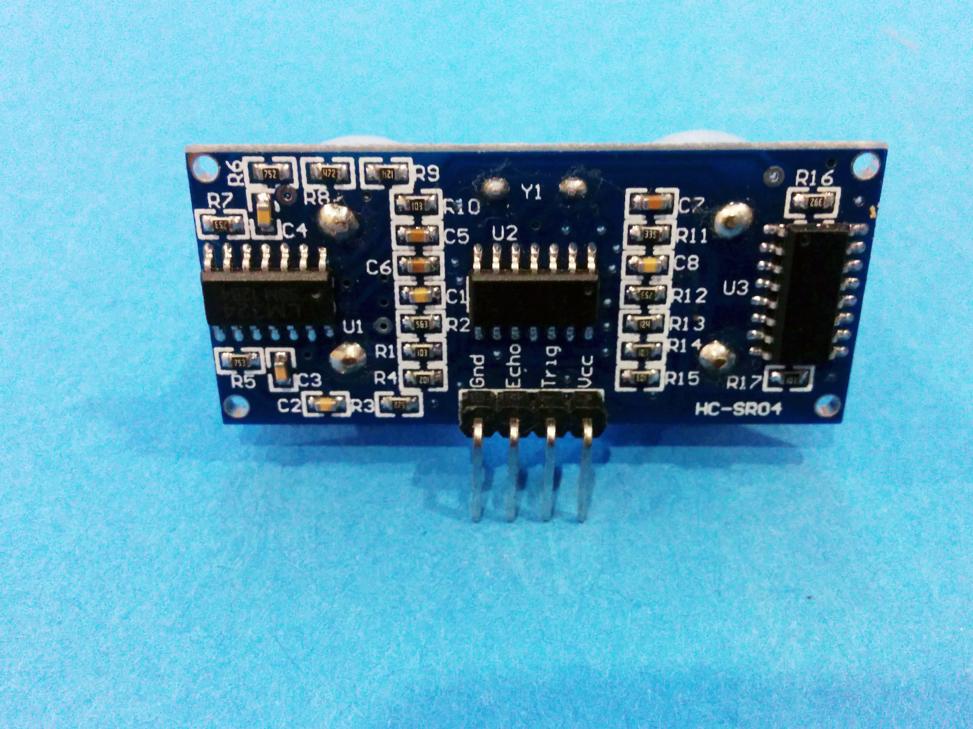
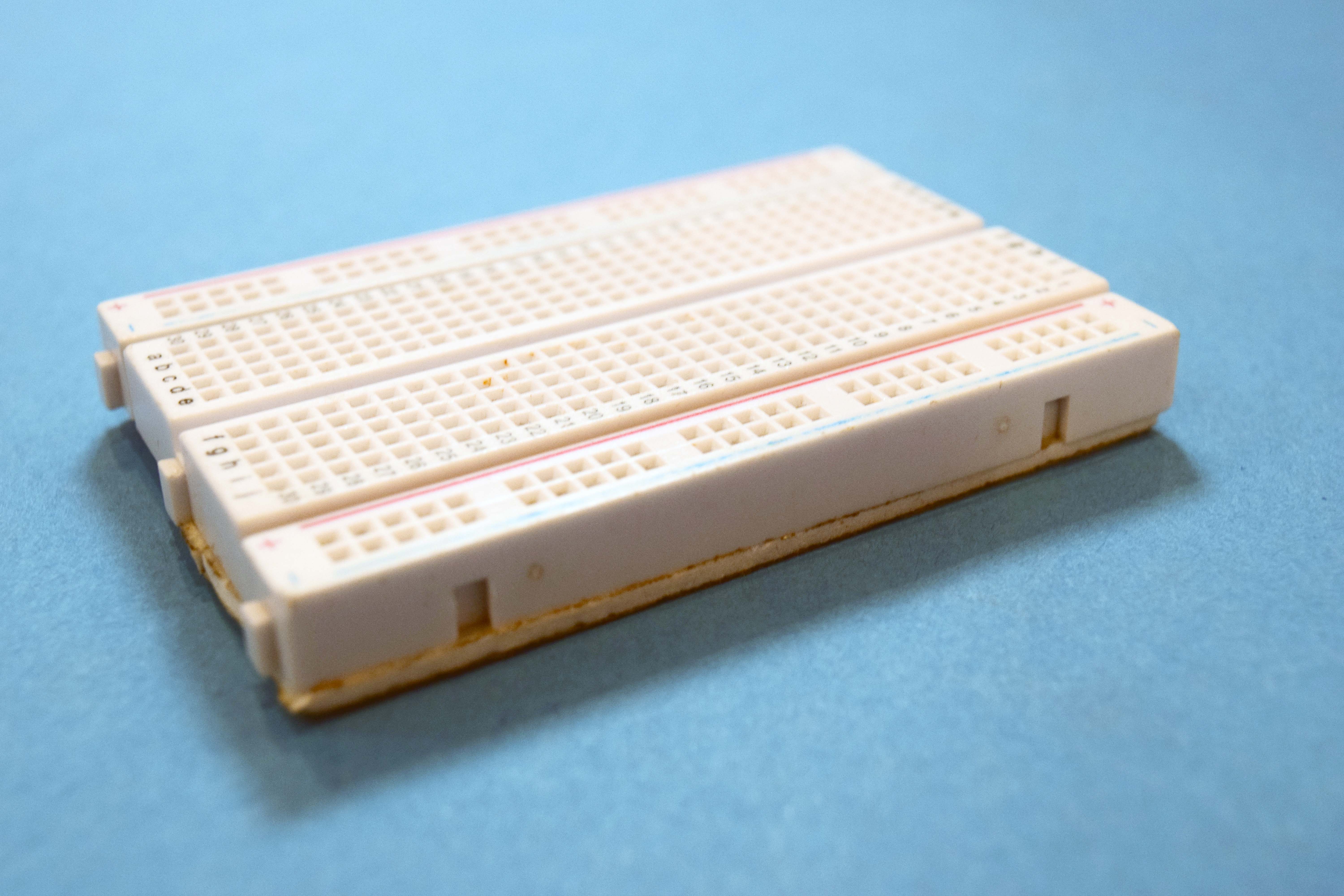
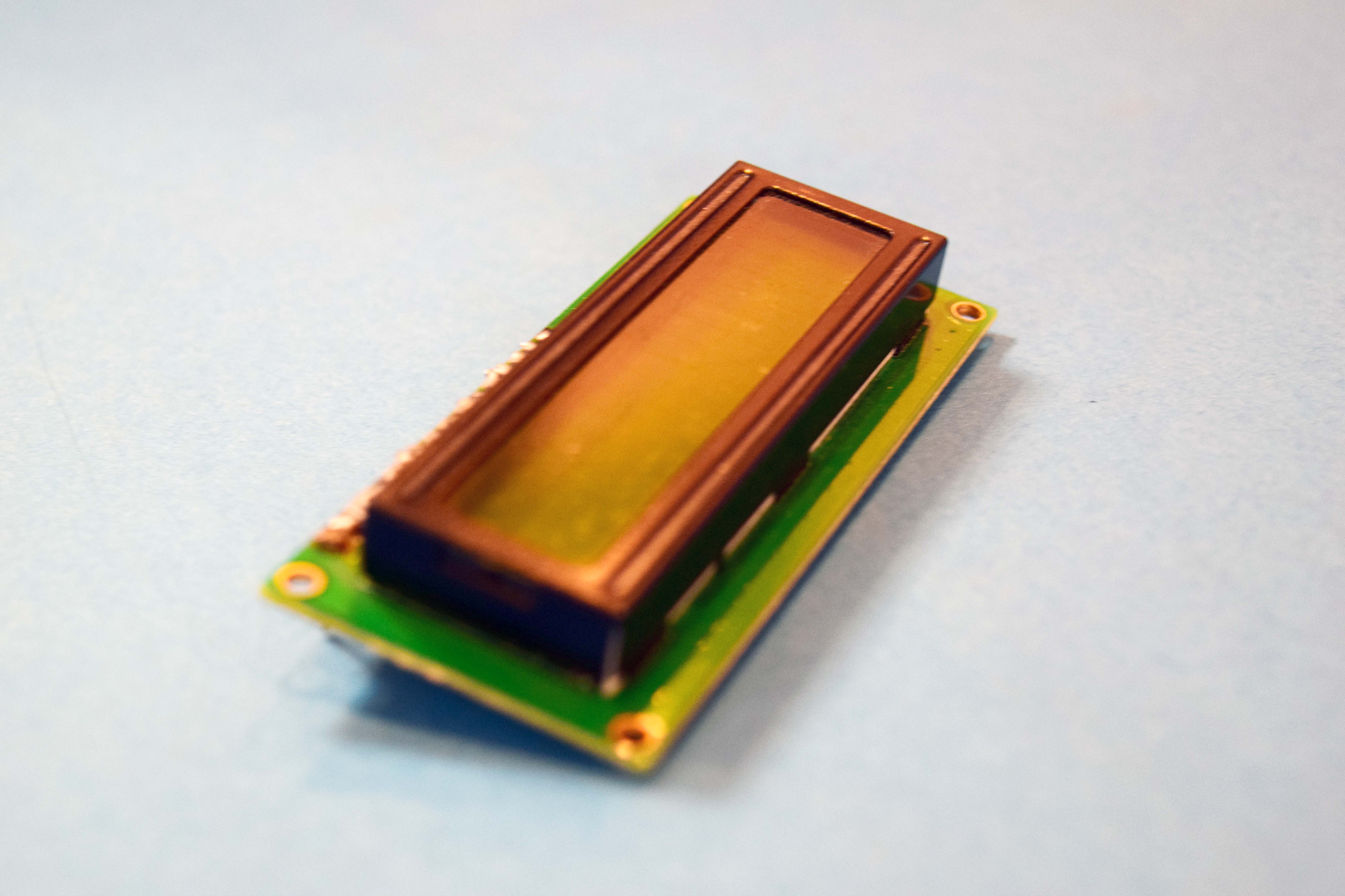
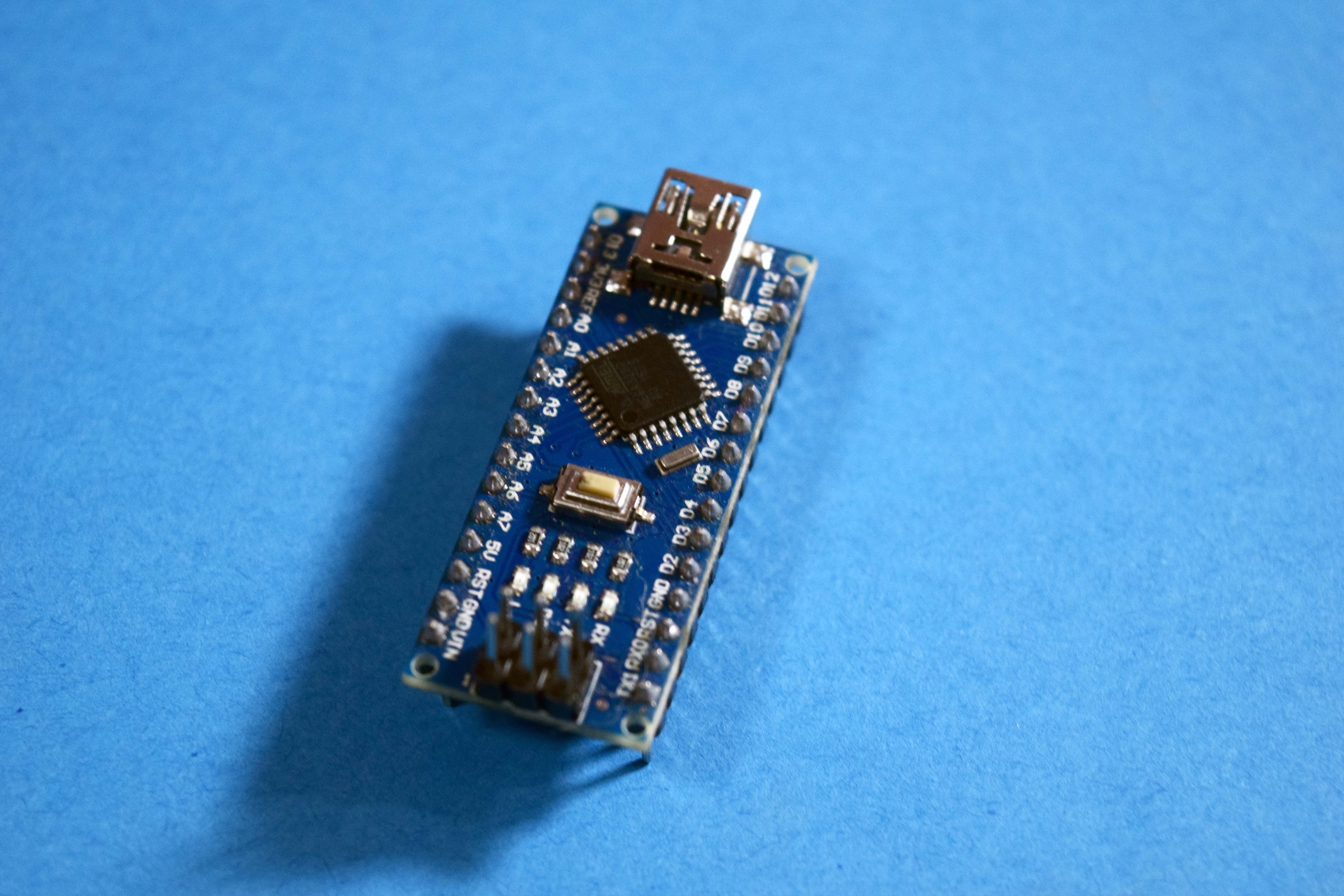
For this project, you will need :
- Arduino Nano
- HC-SR04 Module.
- I2C LCD Driver
- 16x2 LCD.
- Mini USB Cable
- Hook-up wires.
- BreadBoard.
- Connecting Wires
HC-SR04
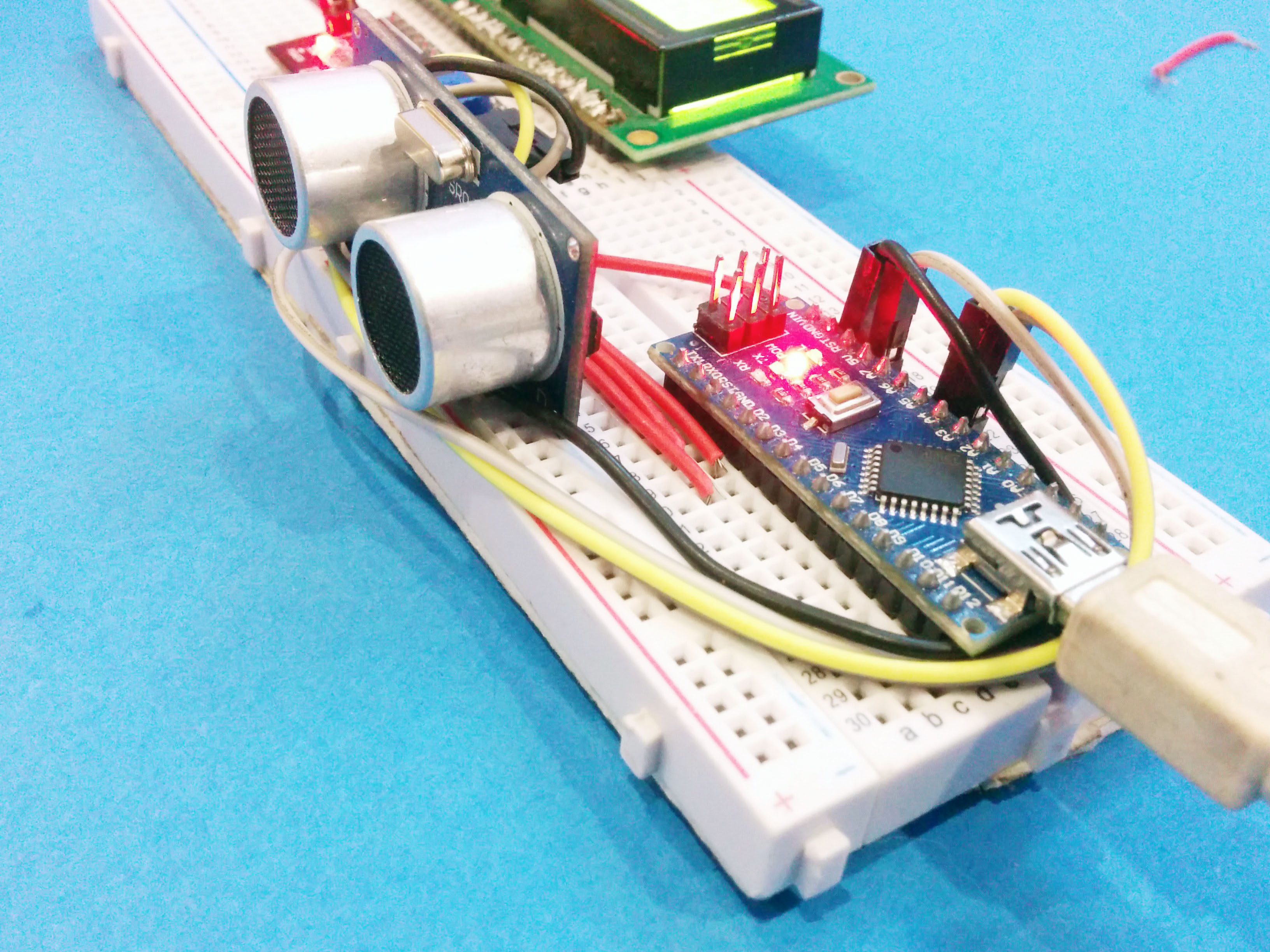

The HC-SR04 is a 5V ultrasonic sensor used in this project and it works great with any arduino board. It produces ultrasonic waves at 40KHz Which hits the obstacle in front of it and reflects back to the sensor and the time taken to for the ultrasonic sound to hit the obstacle and return back determines the distance between the object and the sensor.
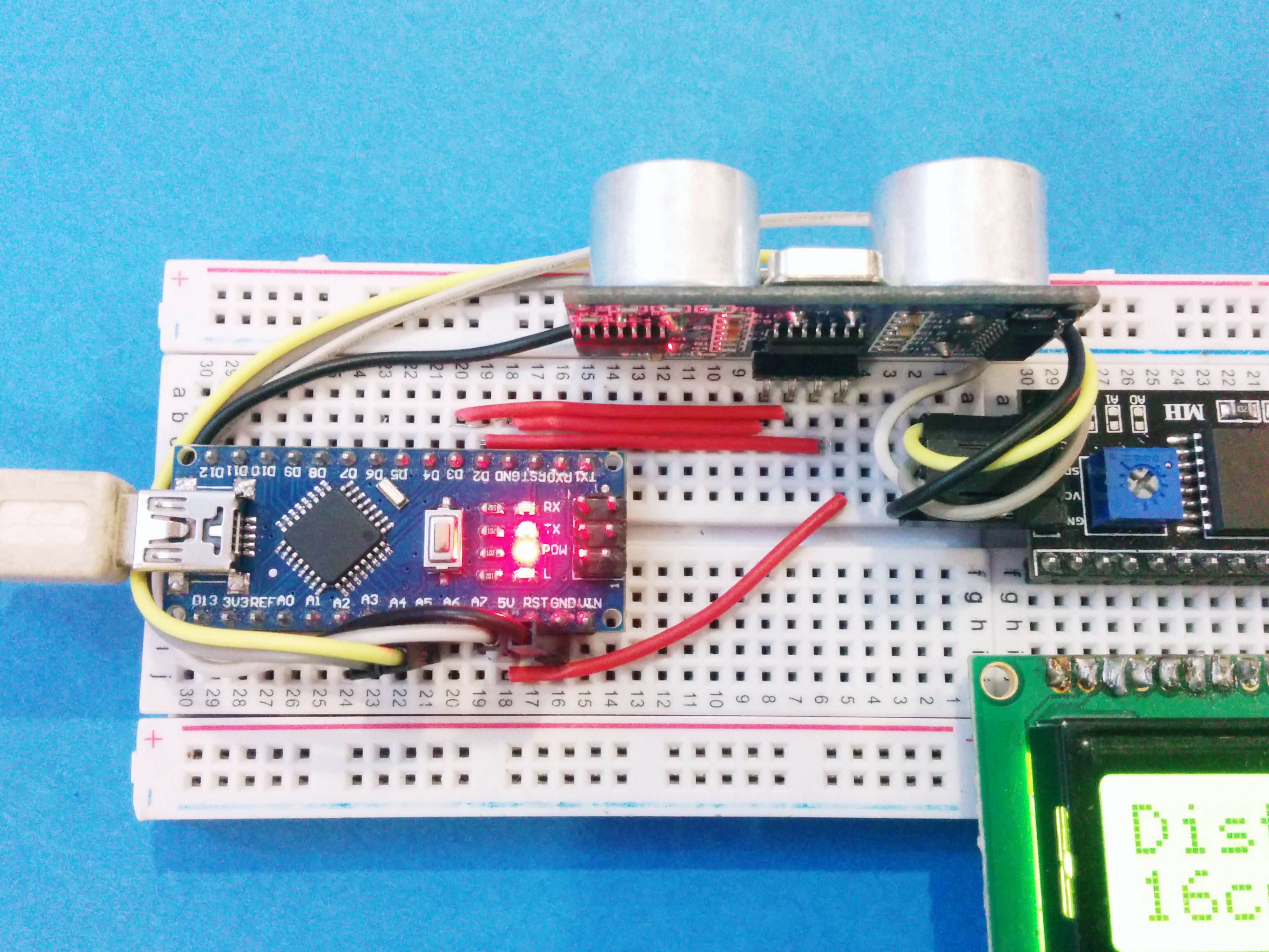
Working with the sensor is very simple and here is how it is connected -
Arduino Nano --> HC-SR04
- 5v -- VCC pin
- Gnd -- Gnd
- D3 -- Trigger Pin
- D2 -- Echo pin
Test Sketch
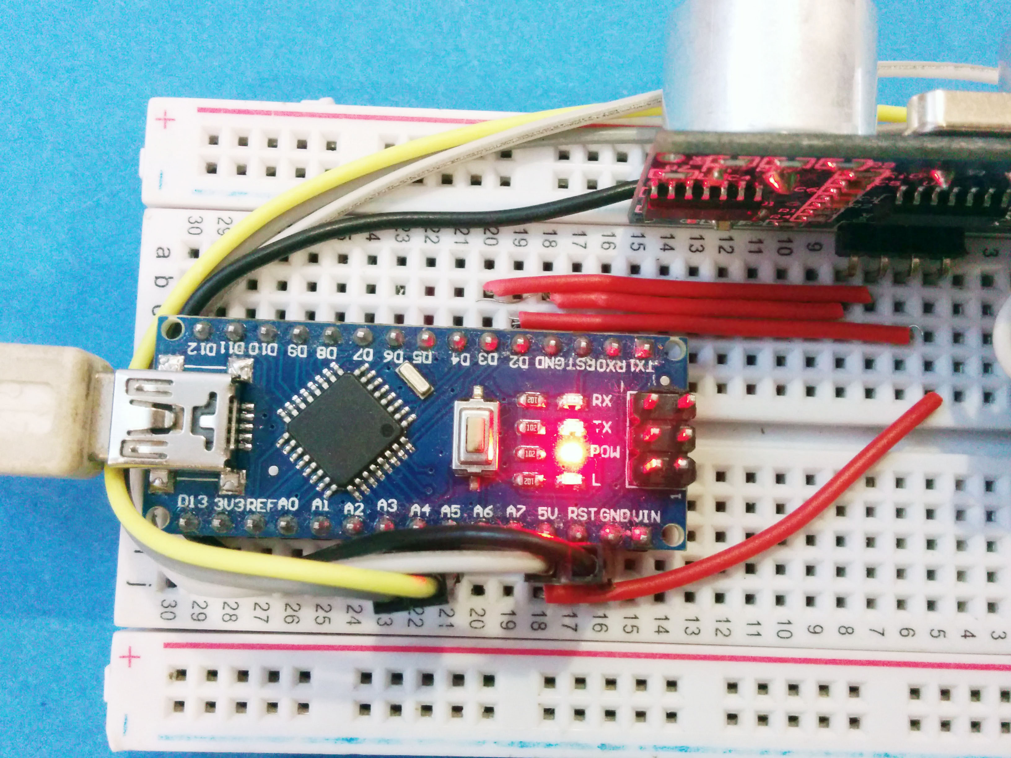
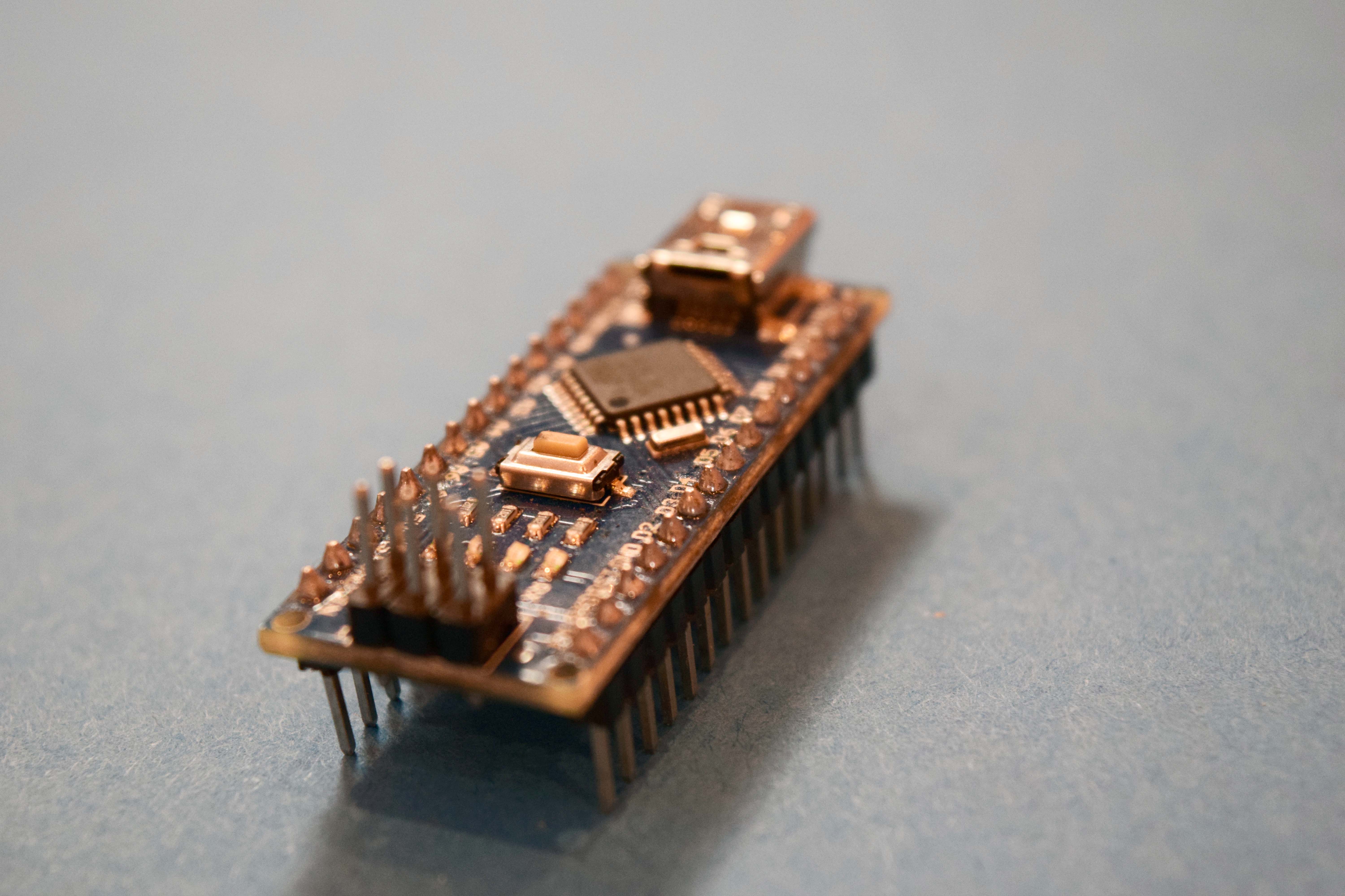
After connecting the HC-SR04 to the Sensor it is now time to upload code to the arduino nano, before we upload the final code lets check out the distance values on a serial monitor to see if everything is working fine and to learn to work with the sensor.
To upload the code to the board you need to download the arduino IDE this can be downloaded form arduino website.
After you have downloaded and installed the IDE select the arduino nano board from the tools menu of the IDE and also the right COM Port or serial port.
Then copy the code from below and paste it in the arduino IDE and hit upload, after the code has uploaded you will see a done uploading text on the bottom of the IDE.
#define echoPin 2 // Echo Pin (OUTPUT pin in RB URF02) #define trigPin 3 // Trigger Pin (INPUT pin in RB URF02)int led = 5; int maximumRange = 350; // Maximum range needed int minimumRange = 0; // Minimum range needed long duration, distance; // Duration used to calculate distance int brightness;
void setup() { Serial.begin (9600); pinMode(trigPin, OUTPUT); pinMode(echoPin, INPUT); pinMode(led, OUTPUT); }
void loop() { // The following trigPin/echoPin cycle is used to determine the distance of the nearest object by bouncing soundwaves off of it. digitalWrite(trigPin, LOW); delayMicroseconds(2); digitalWrite(trigPin, HIGH); delayMicroseconds(10); digitalWrite(trigPin, LOW); duration = pulseIn(echoPin, HIGH); distance = duration/58.2; //Calculate the distance (in cm) based on the speed of sound. Serial.println(distance); // distance in cm brightness= map(distance,1,100,0,255); analogWrite(led, brightness); delay(50); //Delay 50 ms }
LCD
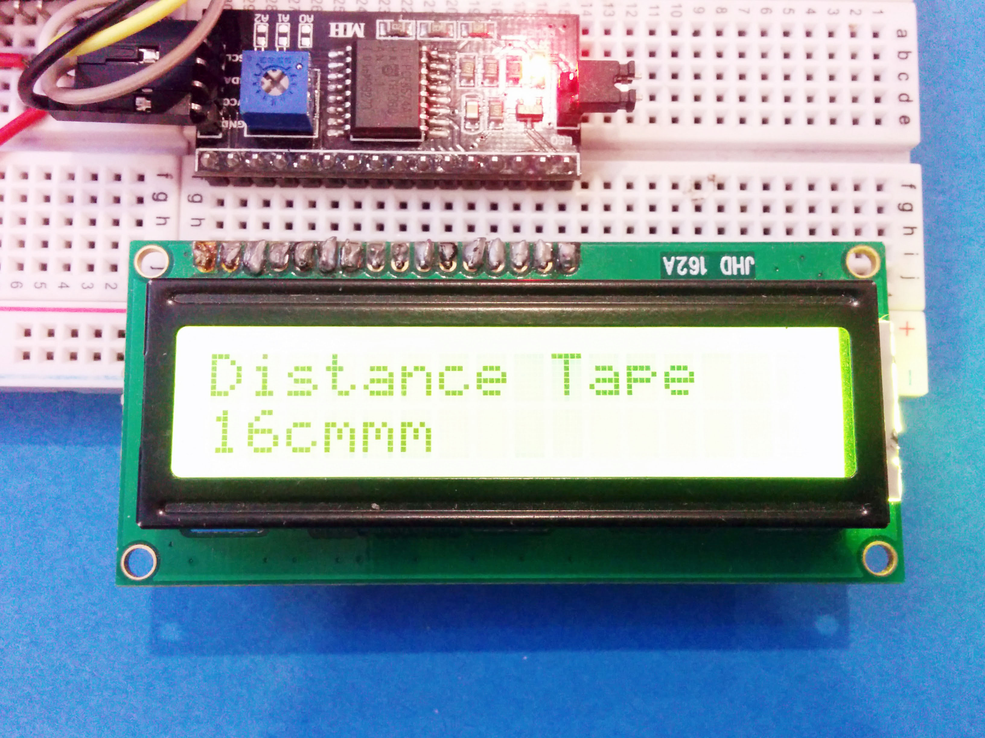
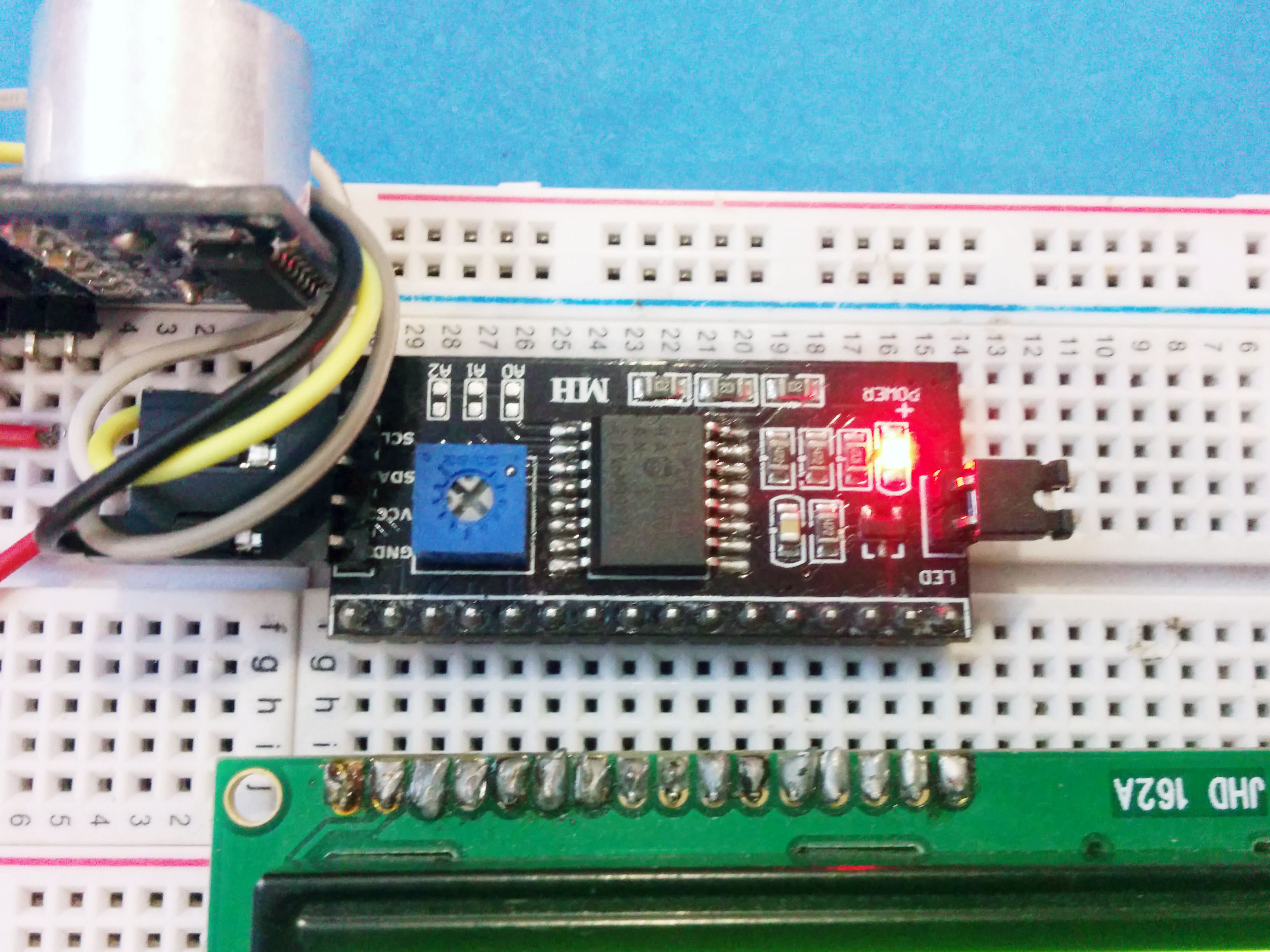
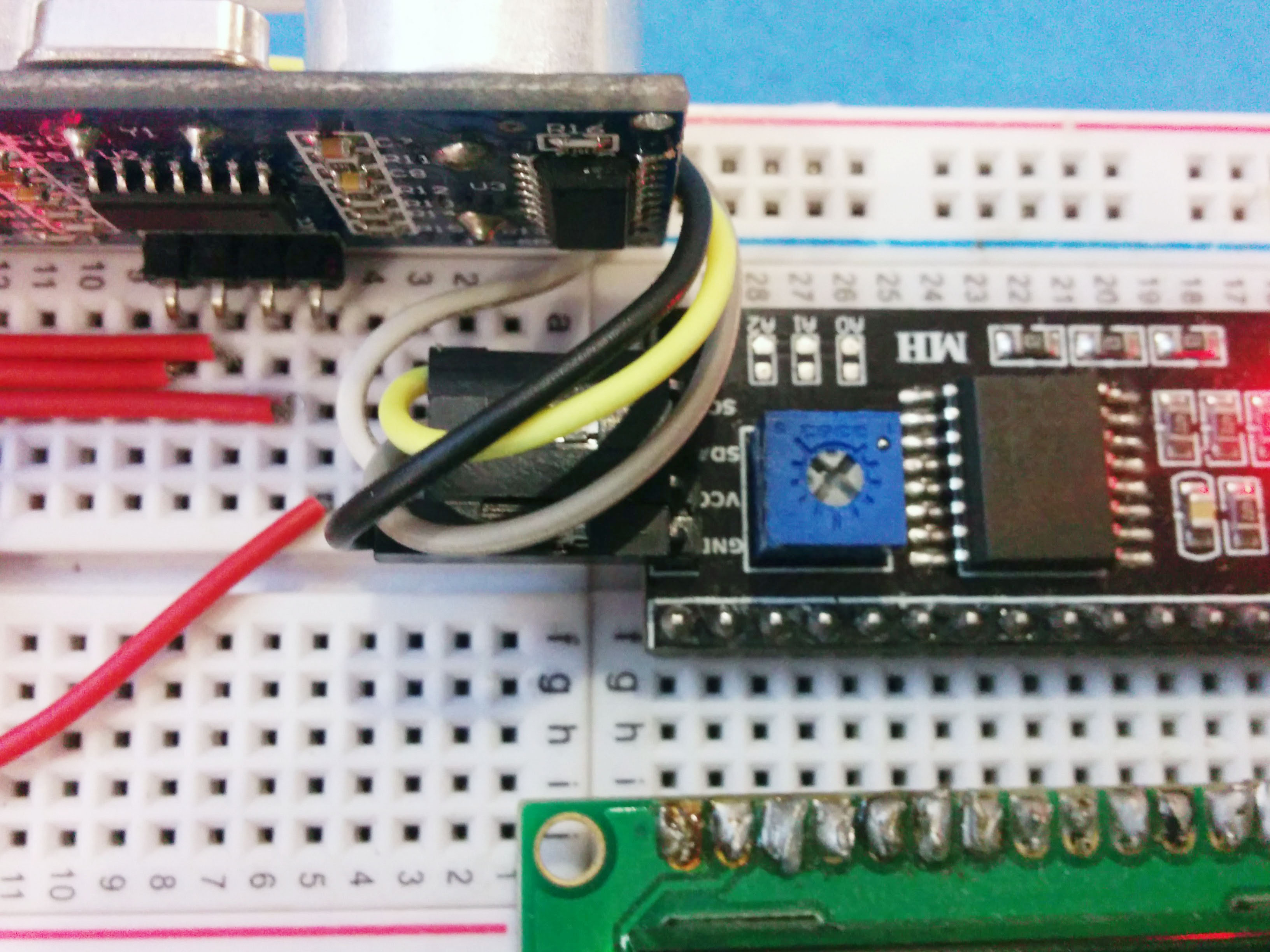
After you have the output on the serial console it is now time to eliminate the PC and display it on your LCD so you can install this project in your garden. For the LCD I'm using an I2C driver this just uses 2 lines rather than a large collection of digital lines connected to the arduino IDE. So you would have more room for more senors to be connected to the arduino nano.
Just follow the circuit as shown in the picture above, if everything went fine you can proceed to the next step where we will upload the final code tho the board.
Code
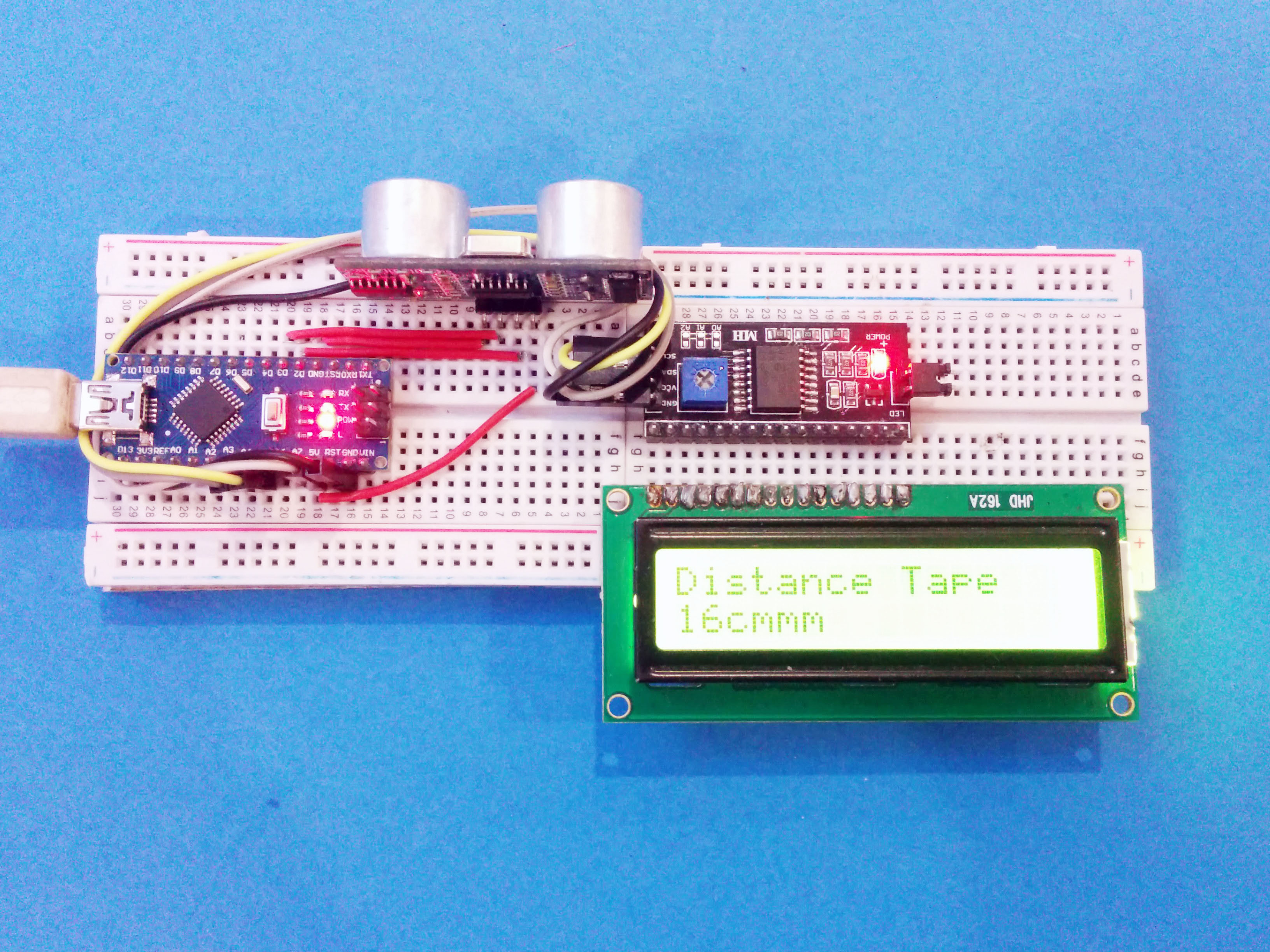
The code is quite simple and is quite similar to that as shown in the step 3 of this project, in addition we are now adding some more libraries to get the I2C LCD working. You can download the libraries form here. Make sure you have entered the right I2C address in the code, the default address of the I2C is 0x3f.
Copy and paste the below code into the arduino and select the arduino nano and the right port and then hit upload.
#include "Wire.h" // For I2C
#include "LCD.h" // For LCD
#include "LiquidCrystal_I2C.h" // Added library* //Set the pins on the I2C chip used for LCD connections //ADDR,EN,R/W,RS,D4,D5,D6,D7 LiquidCrystal_I2C lcd(0x3f,2,1,0,4,5,6,7); // 0x27 is the default I2C bus address of the backpack-see article#define echoPin 3 // Echo Pin (OUTPUT pin in RB URF02) #define trigPin 2 // Trigger Pin (INPUT pin in RB URF02)
int led = 5; int maximumRange = 350; // Maximum range needed int minimumRange = 0; // Minimum range needed long duration, distance; // Duration used to calculate distance int brightness;
void setup() { lcd.begin (16,2); // 16 x 2 LCD module lcd.setBacklightPin(3,POSITIVE); // BL, BL_POL lcd.setBacklight(HIGH); Serial.begin (9600); pinMode(trigPin, OUTPUT); pinMode(echoPin, INPUT); pinMode(led, OUTPUT); }
void loop() { // The following trigPin/echoPin cycle is used to determine the distance of the nearest object by bouncing soundwaves off of it. digitalWrite(trigPin, LOW); delayMicroseconds(2); digitalWrite(trigPin, HIGH); delayMicroseconds(10); digitalWrite(trigPin, LOW); duration = pulseIn(echoPin, HIGH); distance = duration/58.2; //Calculate the distance (in cm) based on the speed of sound. lcd.home (); // Set cursor to 0,0 lcd.print("Distance Tape"); lcd.setCursor (0,1); lcd.print(distance); // Custom text lcd.print("cm"); Serial.println(distance); // distance in cm brightness= map(distance,1,100,0,255); analogWrite(led, brightness); delay(1000); //Delay 50 ms }