Ultra Fine Sharpie EDC
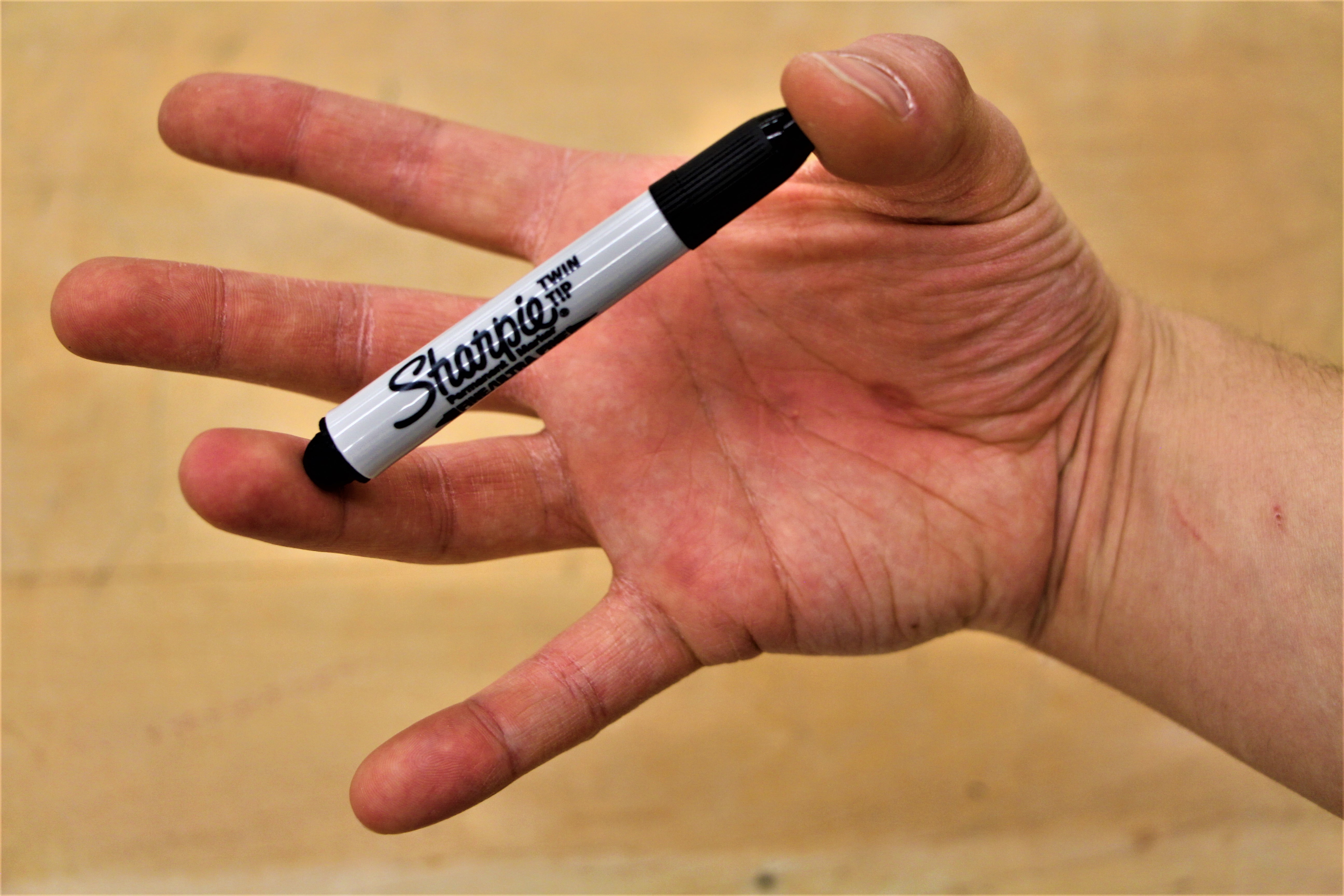
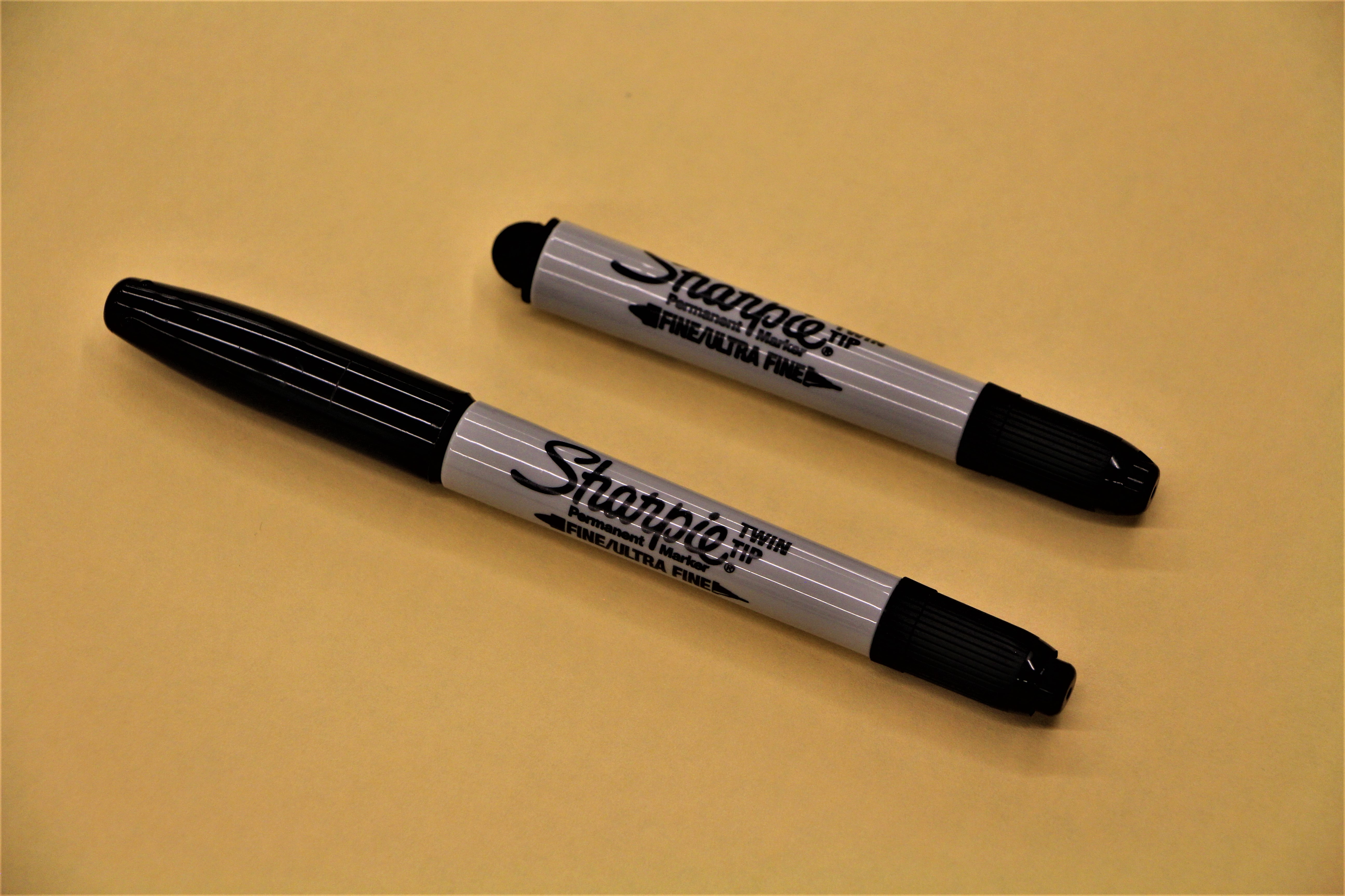
Twin-Tip Sharpies are currently my writing instrument of choice; however, I only use its Ultra Fine Tip. Even though Sharpie makes an Ultra Fine Pen, I find it too skinny and much prefer the girth of the original Sharpie-sized Twin-Tip marker. As they are my preferred writing instrument, I always have one or a few on my person. As I usually stow them in one of the front pockets of my pants, they seem to always end up jabbing me when I sit down; which is rather annoying. I used to carry a Fischer Bullet Space Pen everyday because I would put it in my pocket and never feel it. Fed up with making sacrifices, I decided to modify Sharpie’s Twin-Tip permanent marker/pen and turn it into a real EDC wiriting instrument for myself.
Criteria:
- Analogous Size to Fischer’s Space Pen
- Have a Place to Store the Cap
- Be a Cost-Effective Modification (i.e. Disposable)
- Look Stock
- Retain the Majority of the Ink Cartridge
This is a great project to take advantage of the rapid prototyping and cost effectiveness of 3D printing. It is also a great exercise in 3D modelling. Because there aren’t any complex geometrical shapes in this design, we can use free entry level 3D modelling software such as Tinkercad!
Tools and Materials
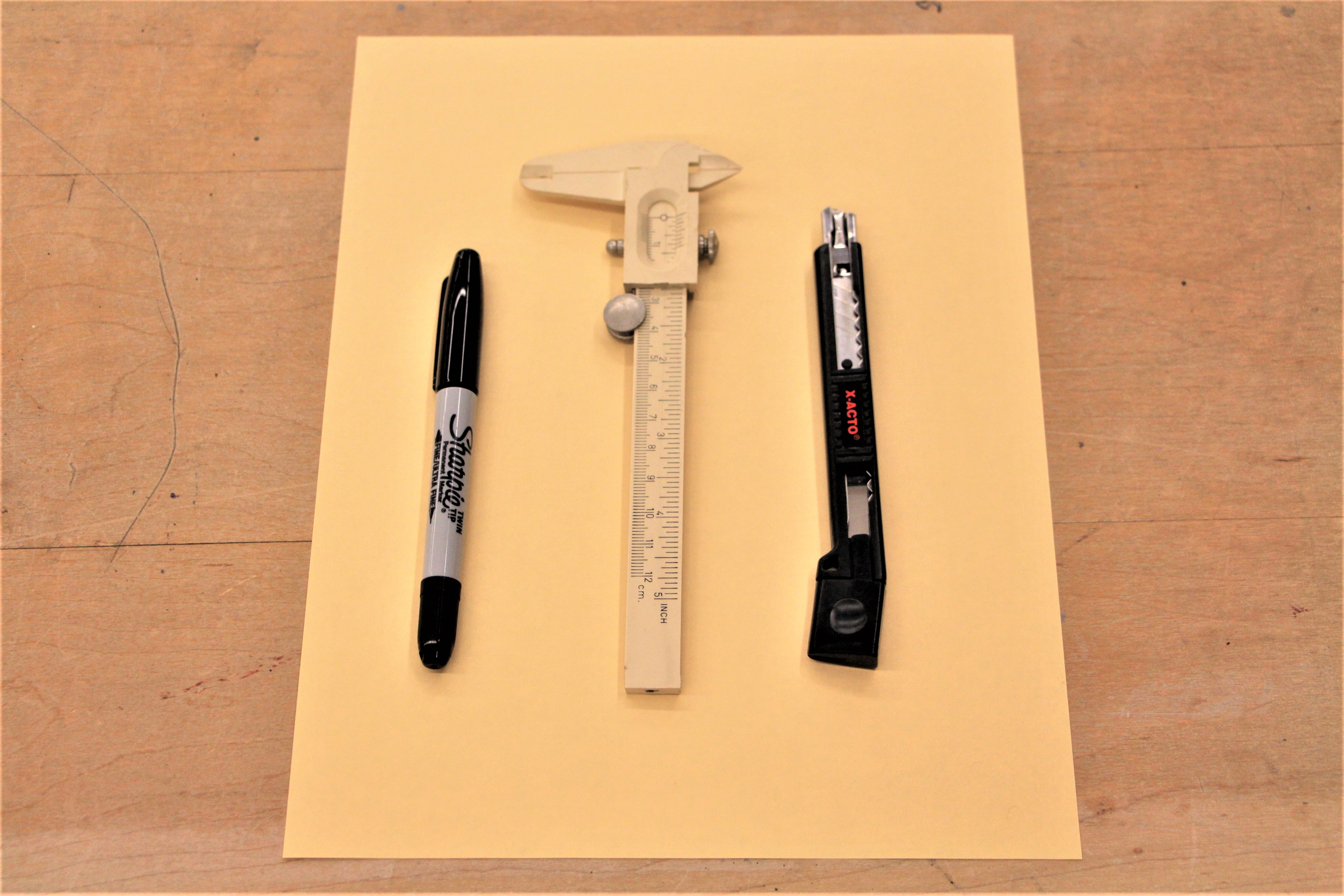
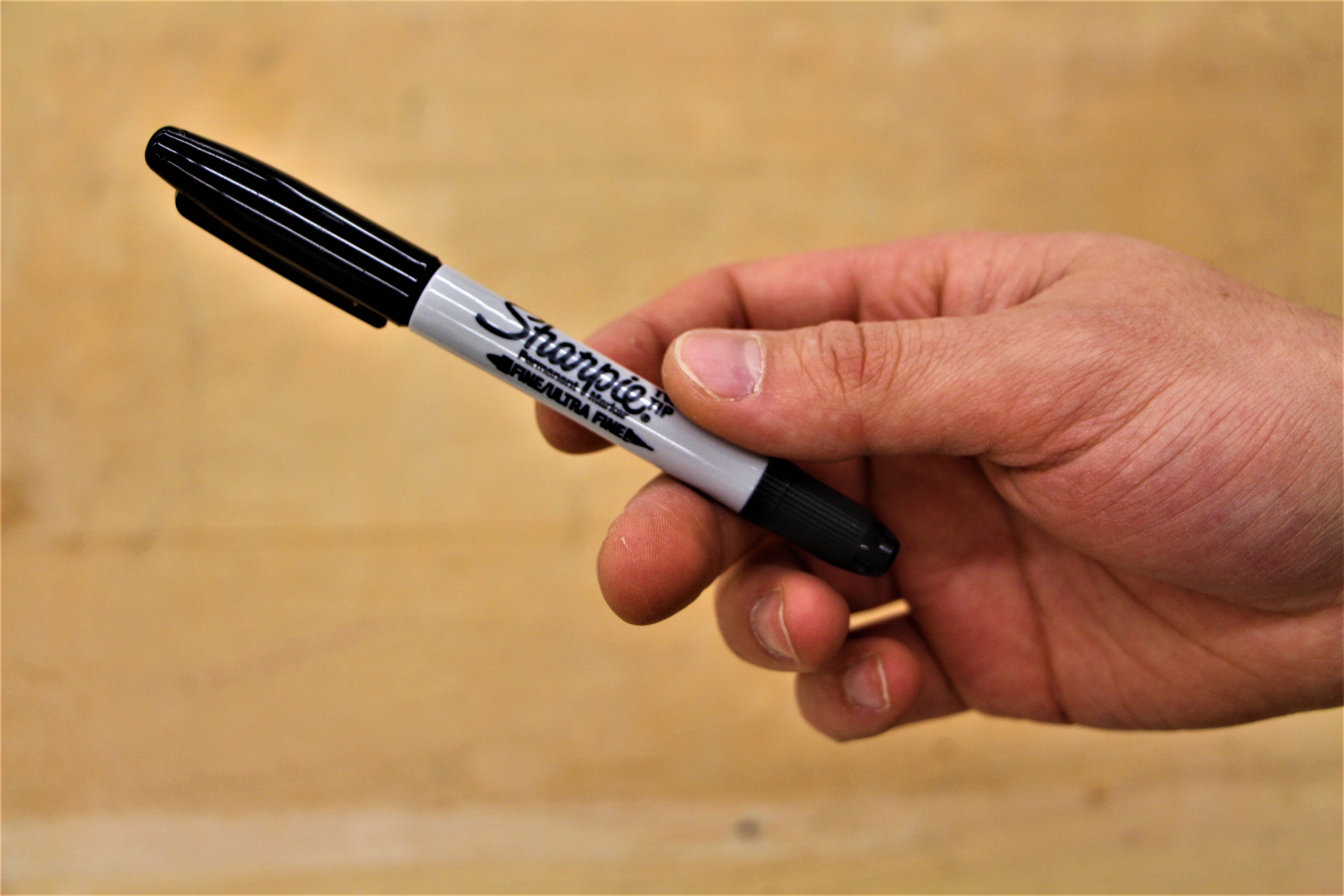
For this EDC hack you'll need:
- A Sharpie Twin-Tip Permanent Marker
- A Utility Knife or Hobby Knife
- Access to a 3D Printer
- Something to protect your work surface (That sheet of paper did not suffice. )
Disassembly
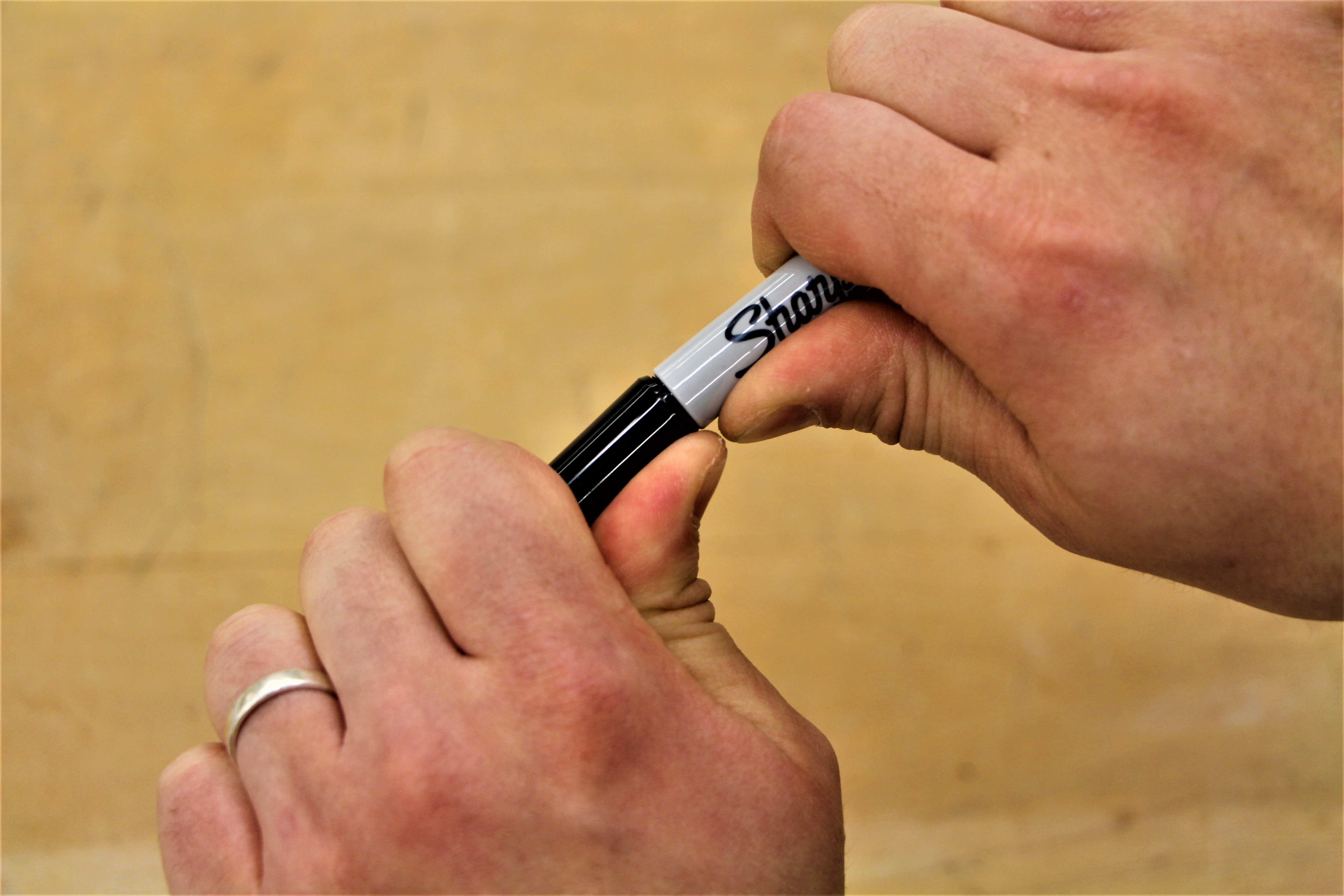
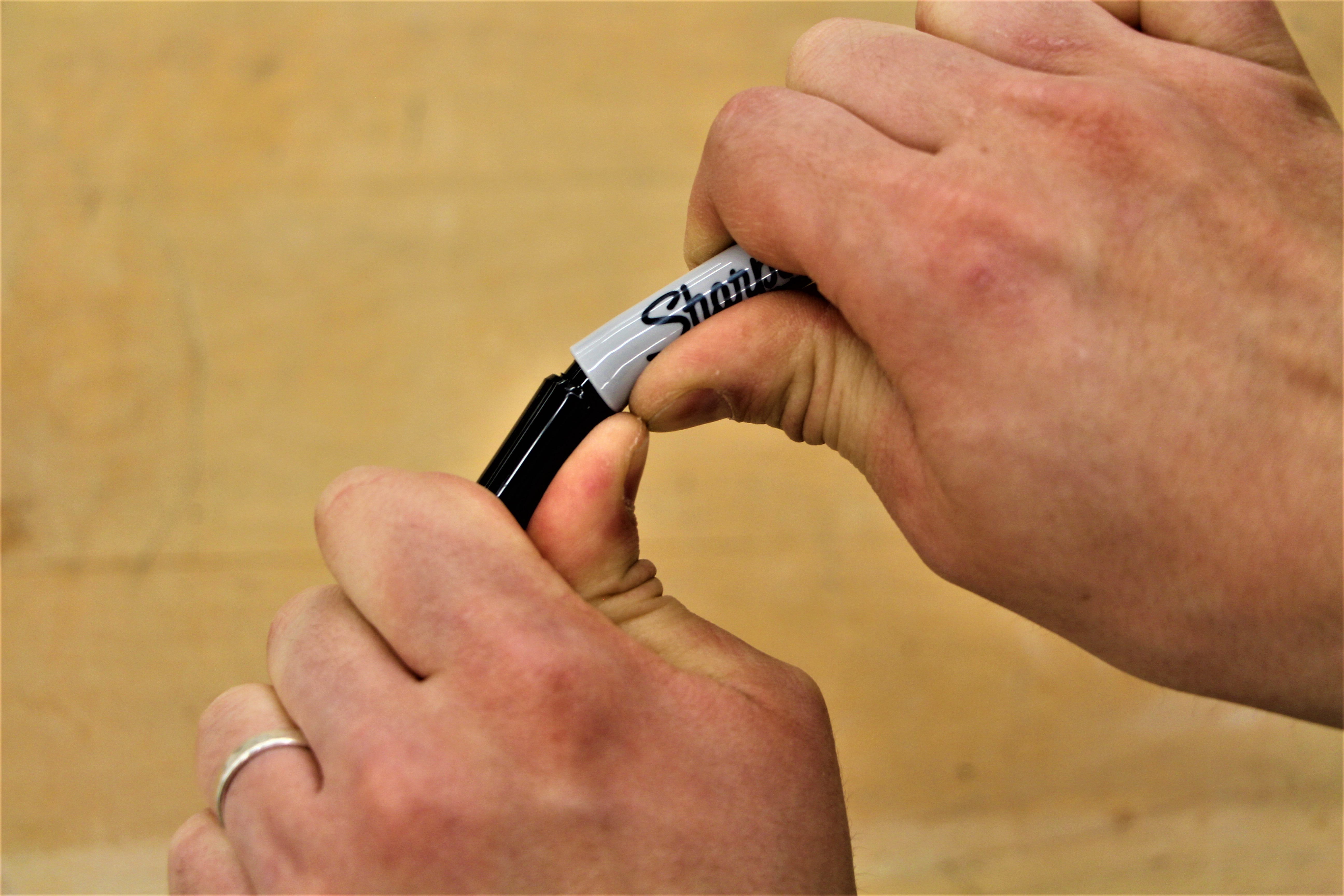
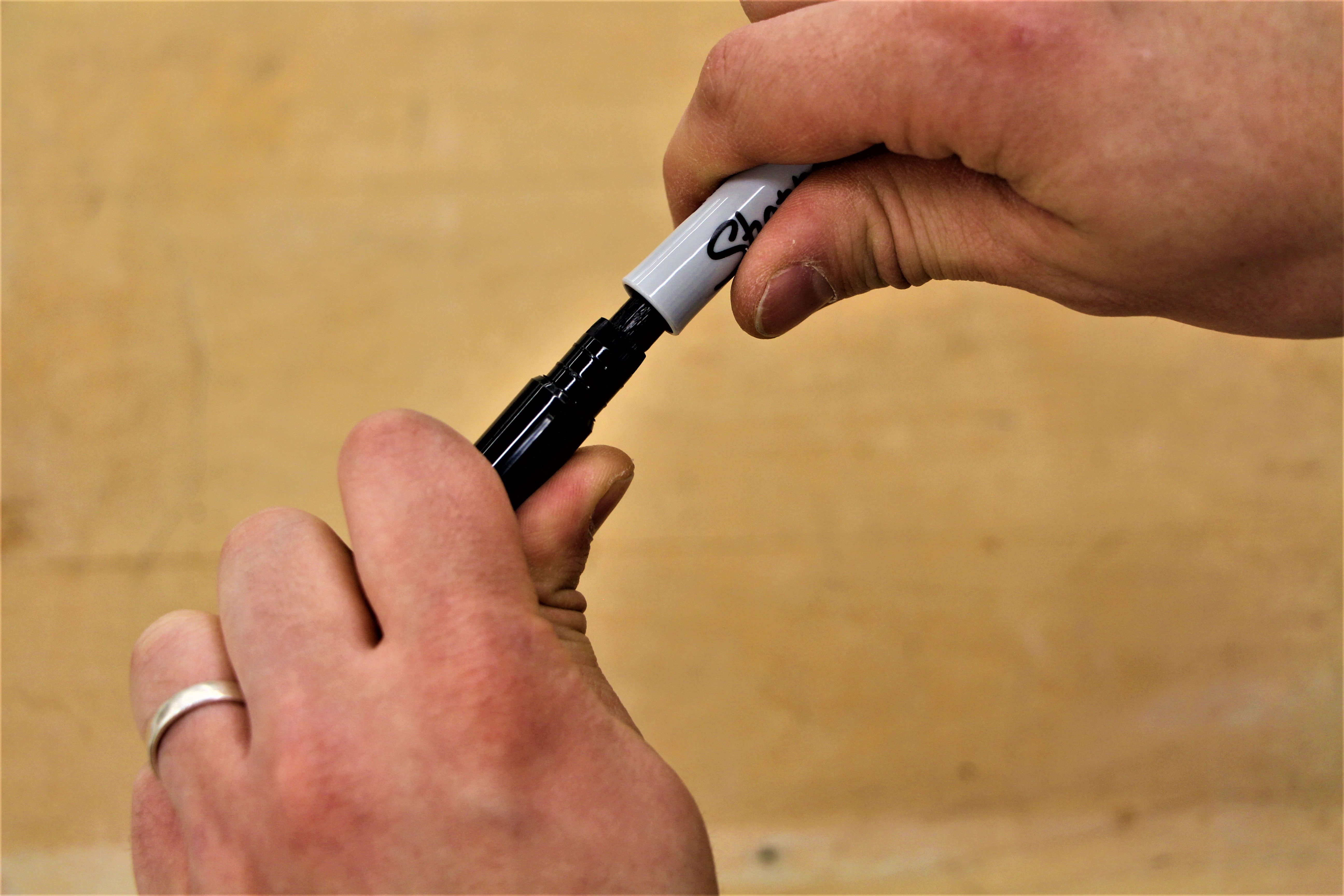
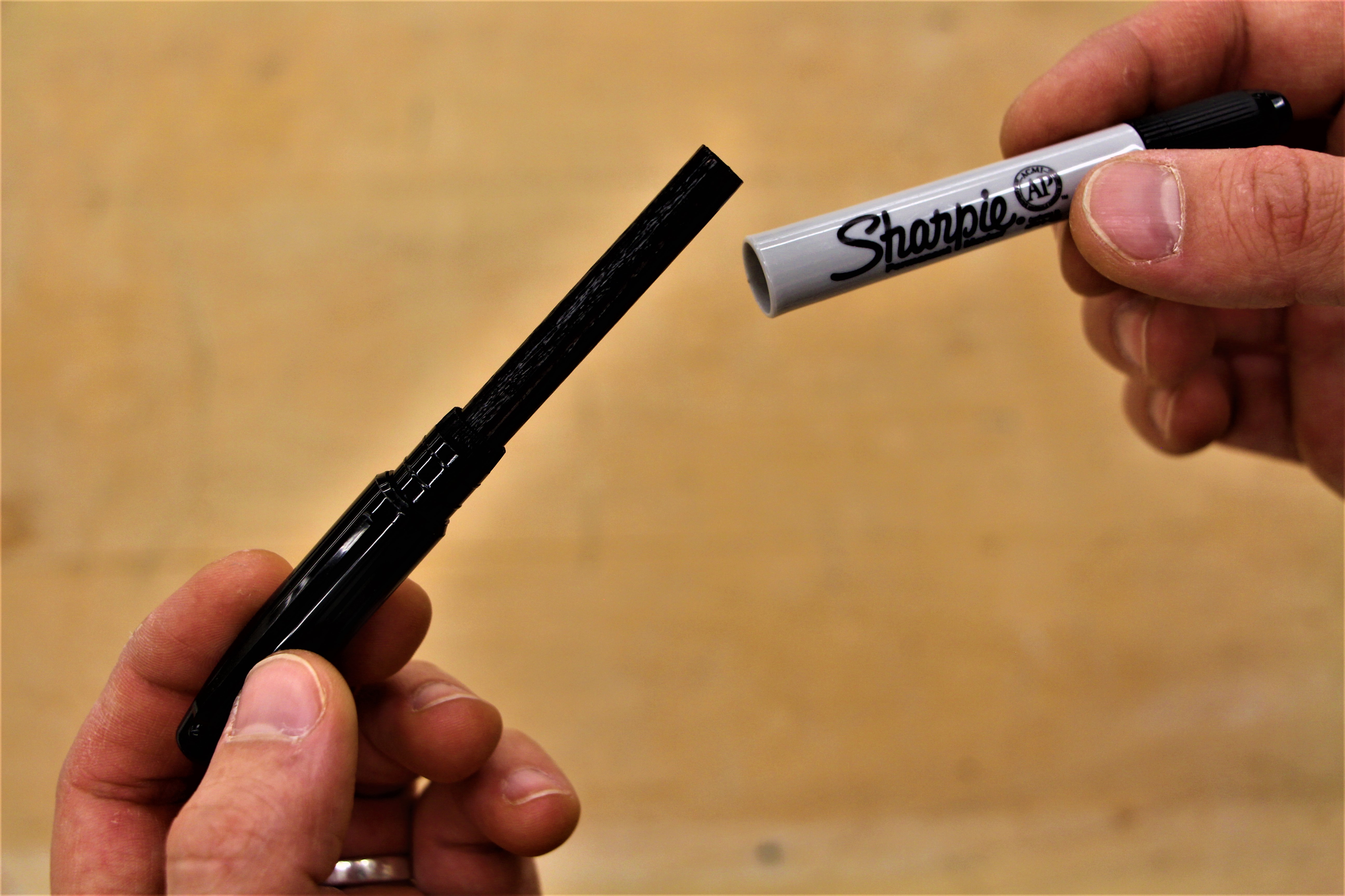
Start by disassembling a sacrificial Twin Tip Sharpie (preferably, one that has dried up ) by firmly grasping the fine tip end (with the cap on ) in one hand and the body of the pen with the other. Slowly start bending the pen at the seam where the cap meets the body back and forth with firm pressure.
Once the seal is broken, keep bending whilst pulling on the capped end until it becomes dislodged from the body of the pen. This might take some practice, but it is the best separation technique that I’ve found. Then, tip the pen body upside down over a piece of paper on a table and tap it until the cartridge falls out.
Measure Twice Print Once…
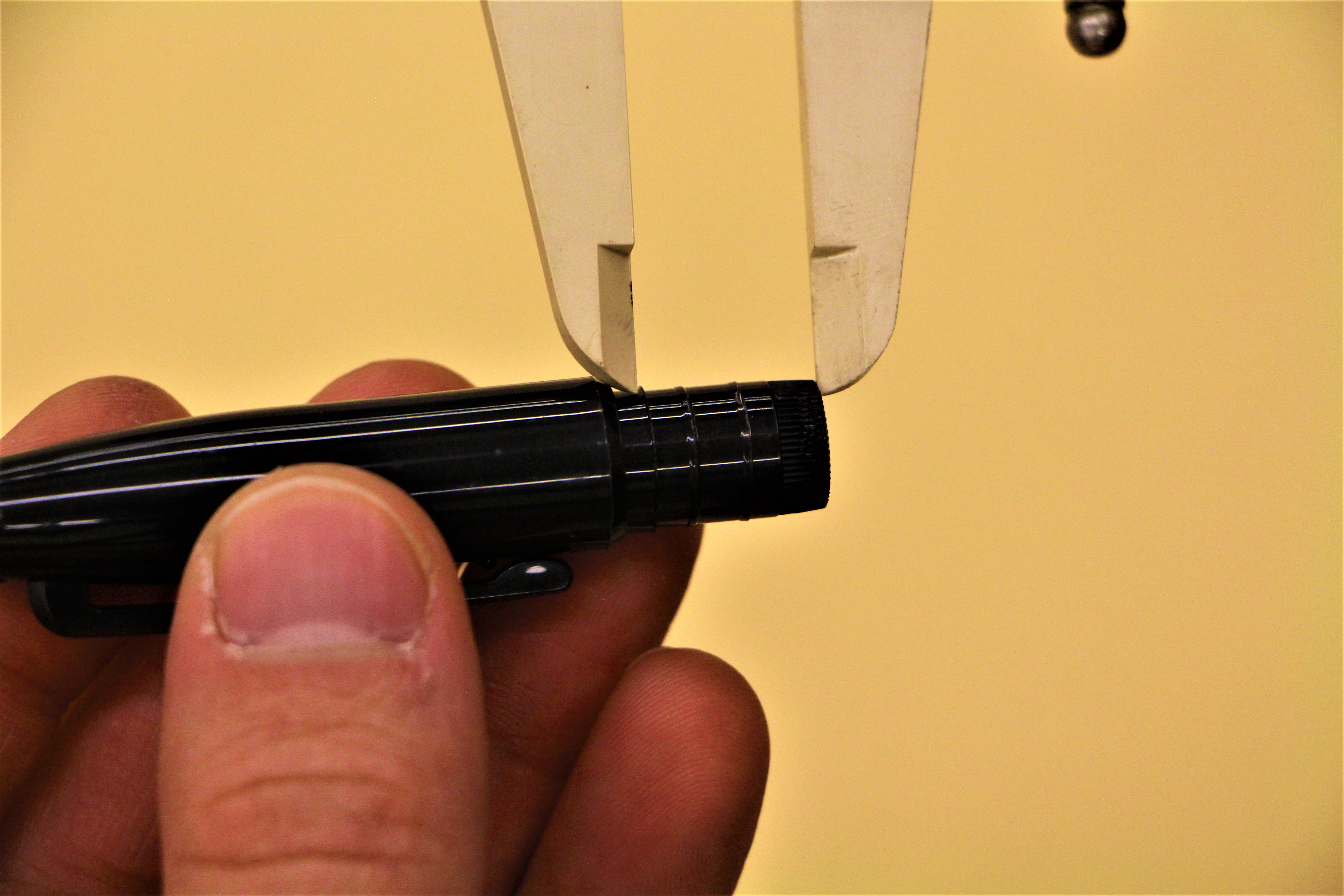
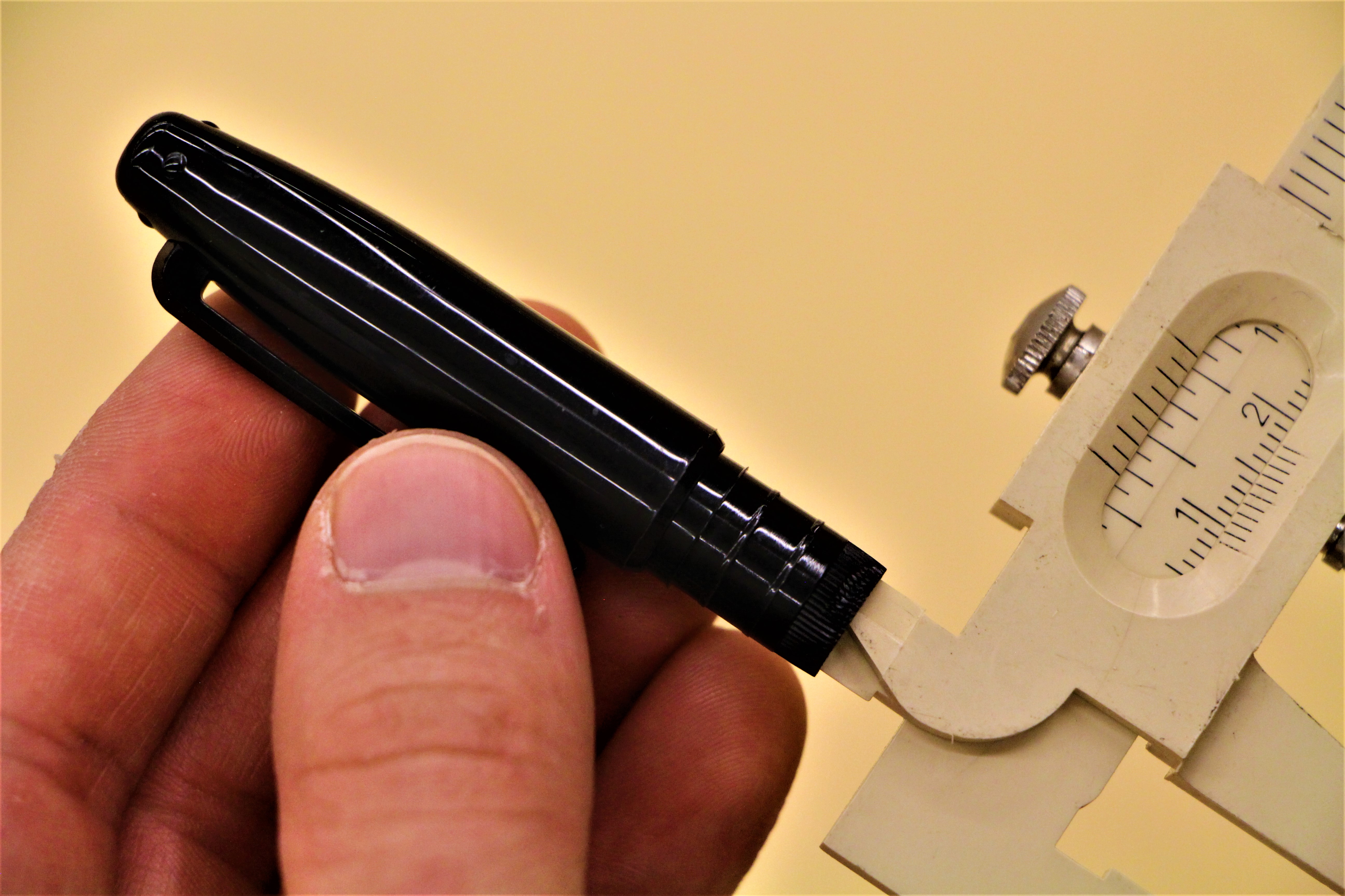
Calipers are an essential tool for making precise 3D modeled objects that fit together seamlessly with other objects. It isn’t essential to have a pair of digital calipers with numerical readouts and simultaneous metric to imperial conversions, a simple pair of Vernier calipers will do (even plastic ones ).
Next, take careful measurements of the inner and outer diameter of the base of the tip that was removed, and the ridges found along its shaft. Measure the distances between the ridges, as well as, the overall length of the base of the tip that was inserted into the body of the pen (up to the cap ).
My measurements were as follows, overall length: 13mm; diameter of the shaft: 10mm; diameter of the ridges: 10.5mm; distance of first ridge from base: 6mm; distance of second ridge from base: 10mm; wall thickness: 1.25mm.
Once you have these measurements, you can start 3D modelling!
3D Modelling With Tinkercad
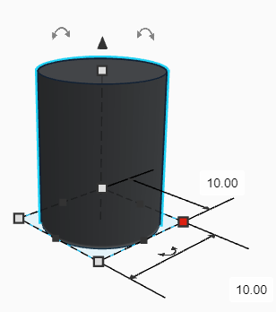
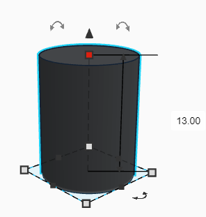
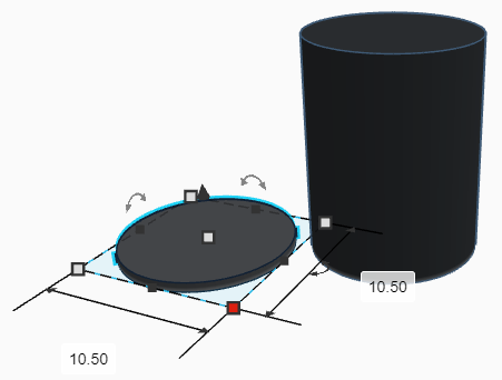
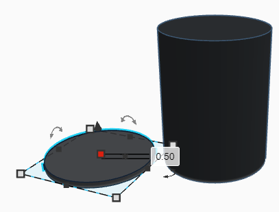
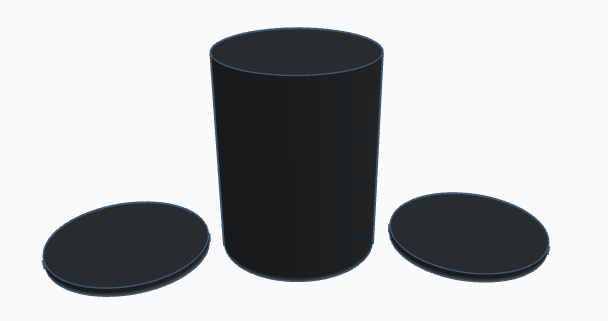
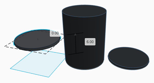
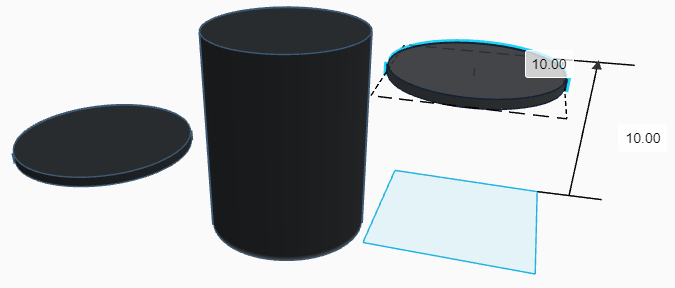
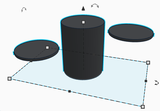
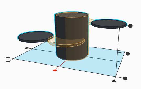
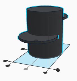
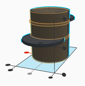
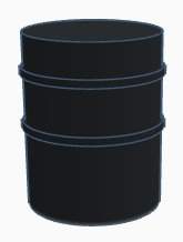
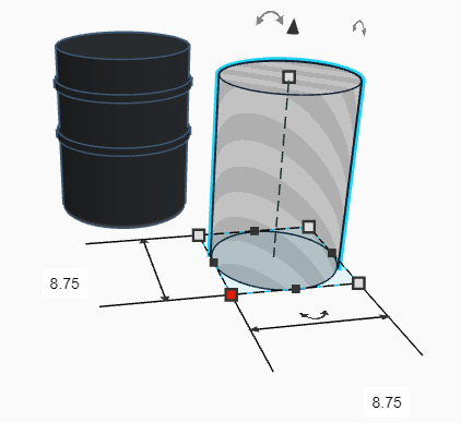
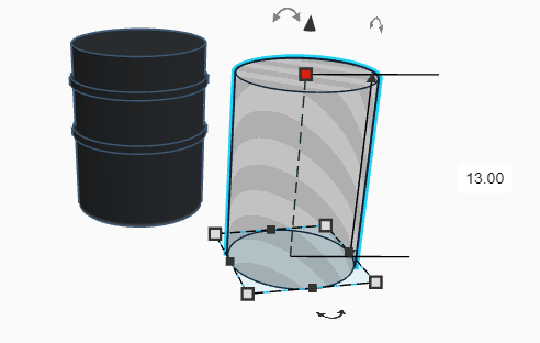
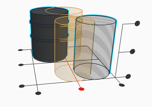
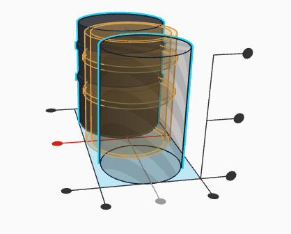
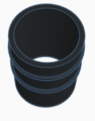
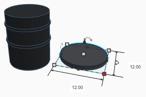
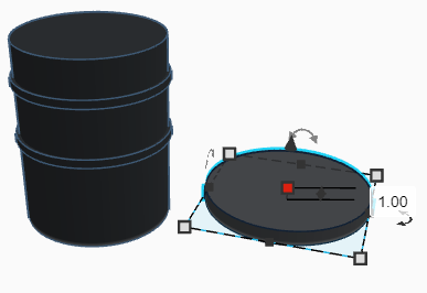
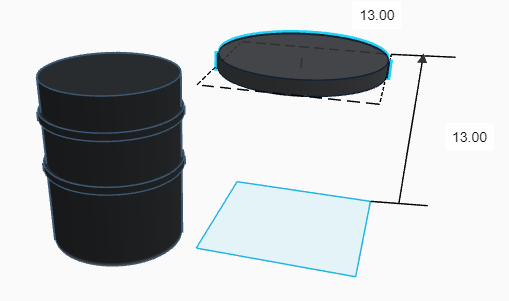
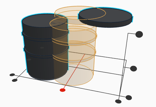
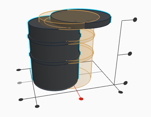
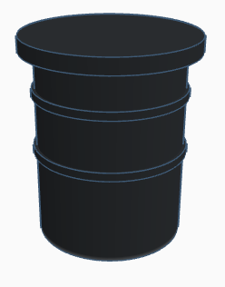
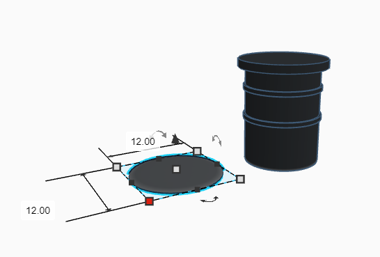
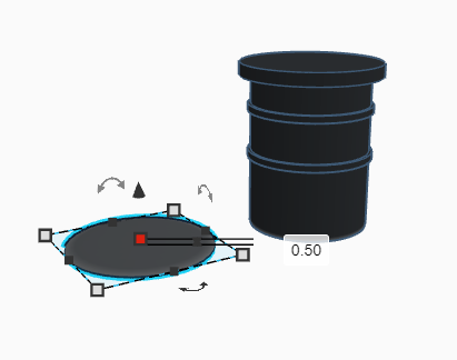
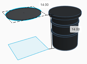
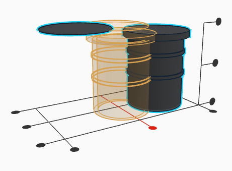
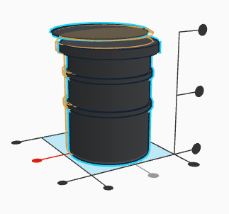
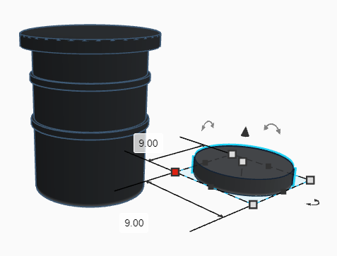
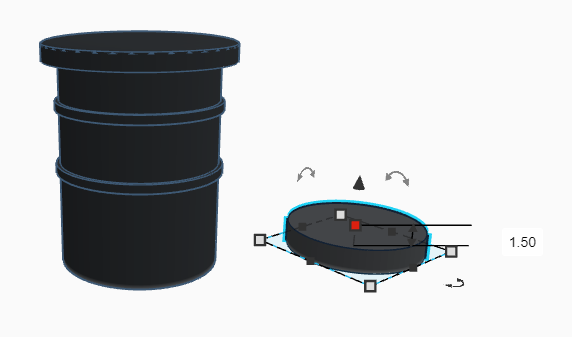
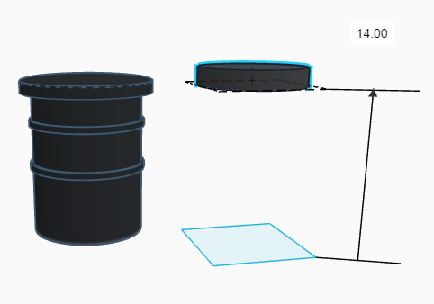
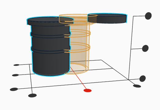
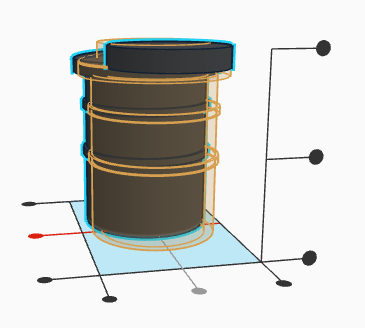
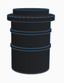
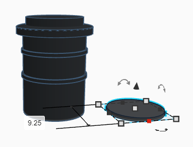
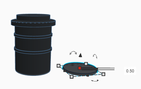
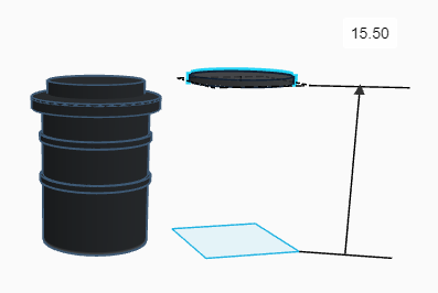
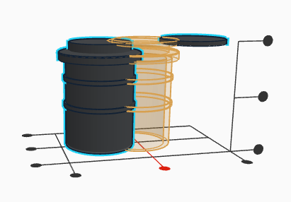
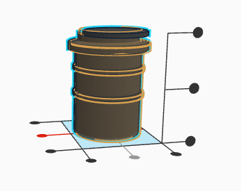
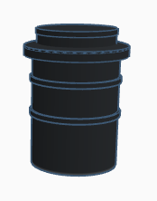
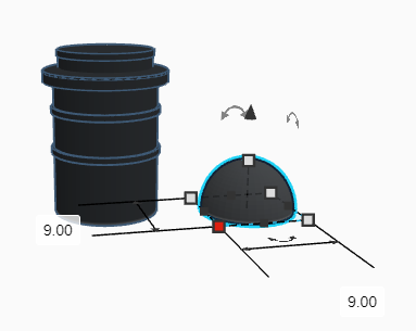
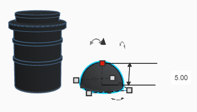
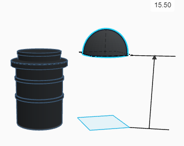
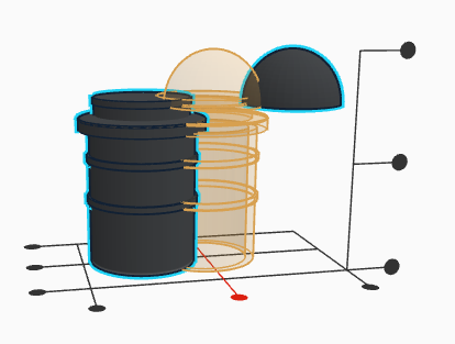
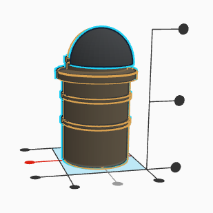
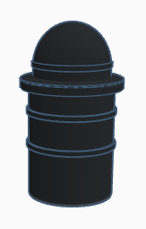
*Please don't be intimidated by this photograph heavy step! The images are merely visual representations of every step and are fairly repetitive.
As I mentioned in the intro, the simple geometric shape of this part allows us to use perhaps the most intuitive, free, browser-based software available, Tinkercad. If you don’t already have a Tinkercad account, create one and follow the tutorials to become familiar with the software. Once you are acquainted, dive in with your measurements and start modelling!
Remember that there are countless approaches to creating a 3D model, the more experienced you become, the more efficient your modelling process will become. To make this tutorial as accessible as possible I chose to eliminate using the tube shape tool to create the body as it requires tube calculations that can be daunting for those with strengths that don’t include math. This 3D modeled part is made up of only 8 shapes!
*To follow the criteria of making it look stock, I changed the colour of the pieces to black. You can simply leave it the default colours or change the colour to any that you prefer!
Start by using the cylinder tool to create a cylinder that is 10mm in diameter by 13mm tall. Next, create a cylinder that is 10.5mm in diameter by 0.5mm tall and duplicate it. Then, elevate one of the 10.5mm x 0.5mm cylinders to 6mm and then the other to 10mm. Select all three cylinders by holding down the shift key and press ‘’L’’ to bring up the Align Tool. Align the pieces in the center of both the X and Y axes. You’ll find that the Align Tool is indispensable when modelling. To complete the shaft, create a cylinder, using the cylinder hole tool, that is 8.75mm in diameter by 13mm tall. Align it with the three other cylinders in the same way as the previous step and Group all the cylinders together. This will create a hole in the center of the shaft and a wall thickness of 1.25mm.
Now, we must create a stopper piece for the top of the shaft to catch on the body of the pen. Start by creating a cylinder 12mm in diameter and 1mm tall. Elevate the cylinder to 13mm and Align and Group it to the others. To round off the profile of the top of the cylinder (purely aesthetic ), use the hemisphere tool to create a hemisphere that is 12mm in diameter by 0.50mm tall. Elevate the hemisphere to 14mm, Align and Group it with the others. The piece is now fully functional but doesn’t meet the criteria of cap storage.
To remedy this, we’ll add a couple more cylinders and a hemisphere to the top based on the internal dimensions of the fine tip cap. First, create a cylinder that is 9mm in diameter by 1.5mm tall, then Elevate it to 14mm, Align and Group it to the other pieces. Next, create another cylinder that is 9.25mm in diameter by 0.5mm tall, Elevate it to 15.5mm, Align and Group it to the other pieces. Lastly, create a hemisphere that is 9mm in diameter by 5mm tall, Elevate it to 15.5mm, Align and Group it with the others. Congrats, that concludes the 3D modelling for this project!
This project was made public thanks to JamesCielen's excellent suggestion! Here's a direct link to my Tinkercad page!
Printing!
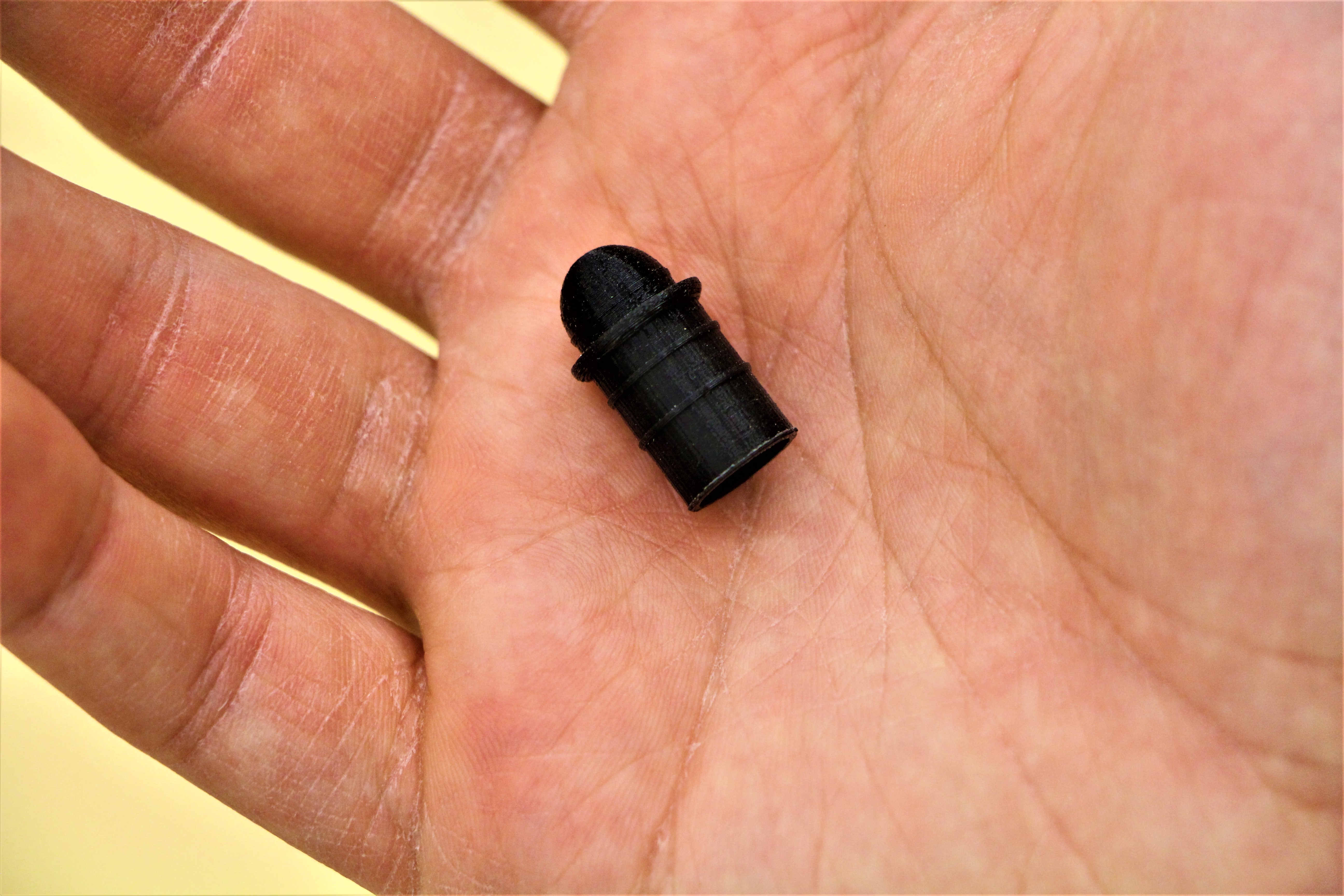
Export the model as an .OBJ file from Tinkercad and upload it into your preferred slicing software. I usually print these types of parts in ECO-ABS or Nylon for increased strength and durability. Because the part is so small, I usually tack on a brim and support material to help it adhere to the build platform but try it without first.
Using high quality settings at 100% infill with the brim and support material, the print takes less than 10 minutes! Experiment to find the best print settings for your printer!
I printed the pieces vertically but printing them horizontally could give them a bit more lateral strength; however, I haven’t had an issue with the ends shearing off even after months of quotidian use.
Final Assembly!
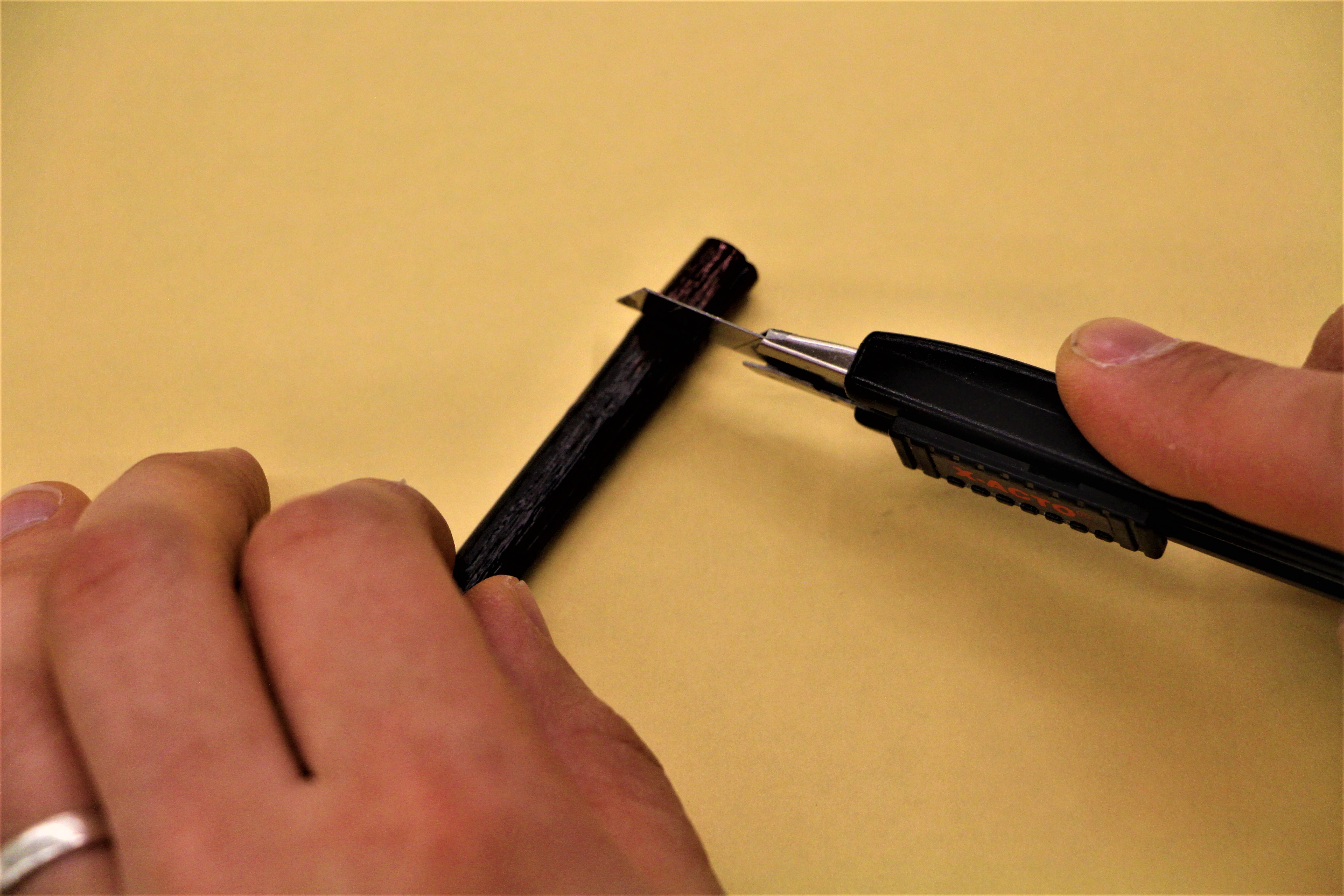
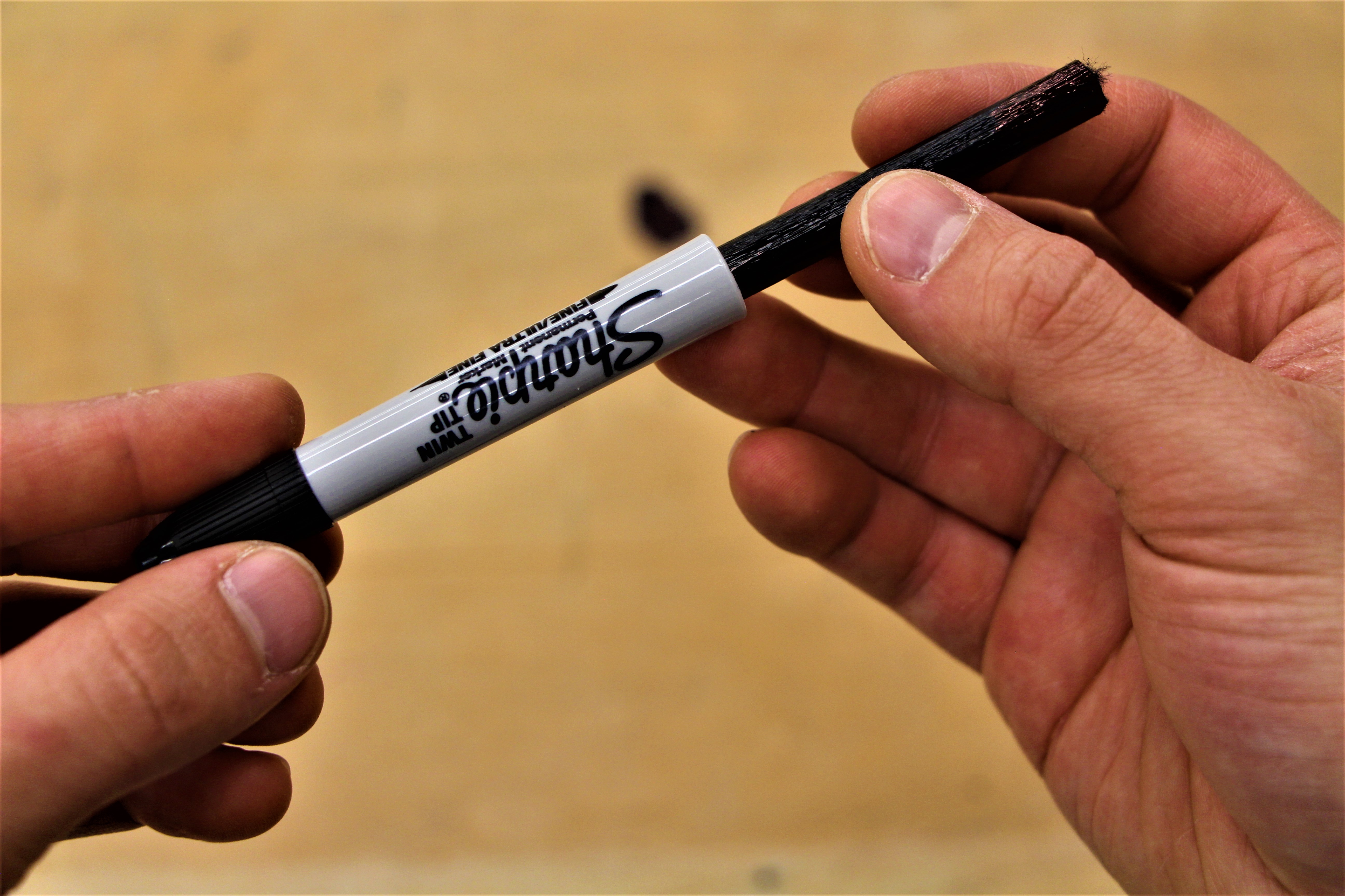
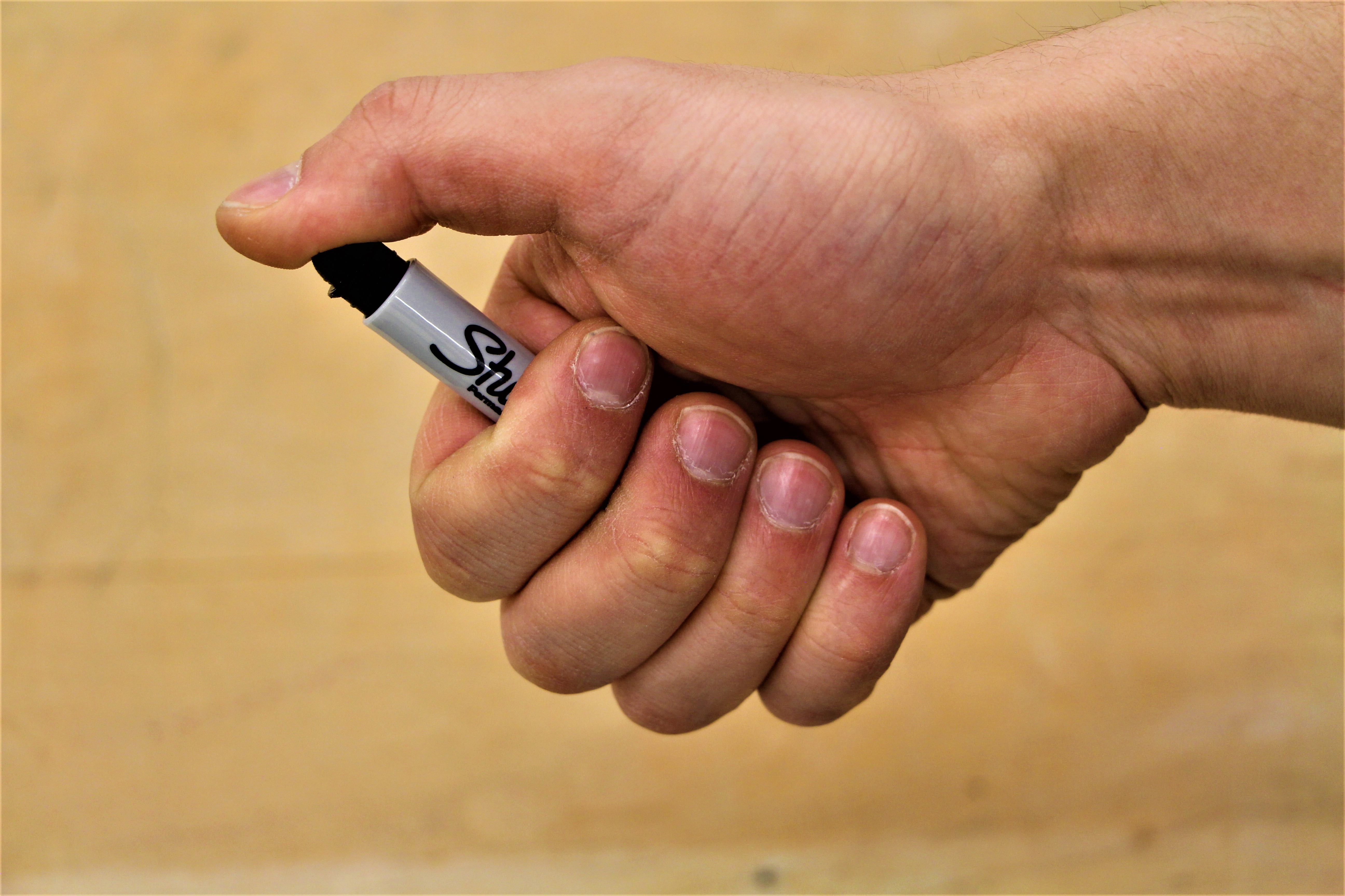

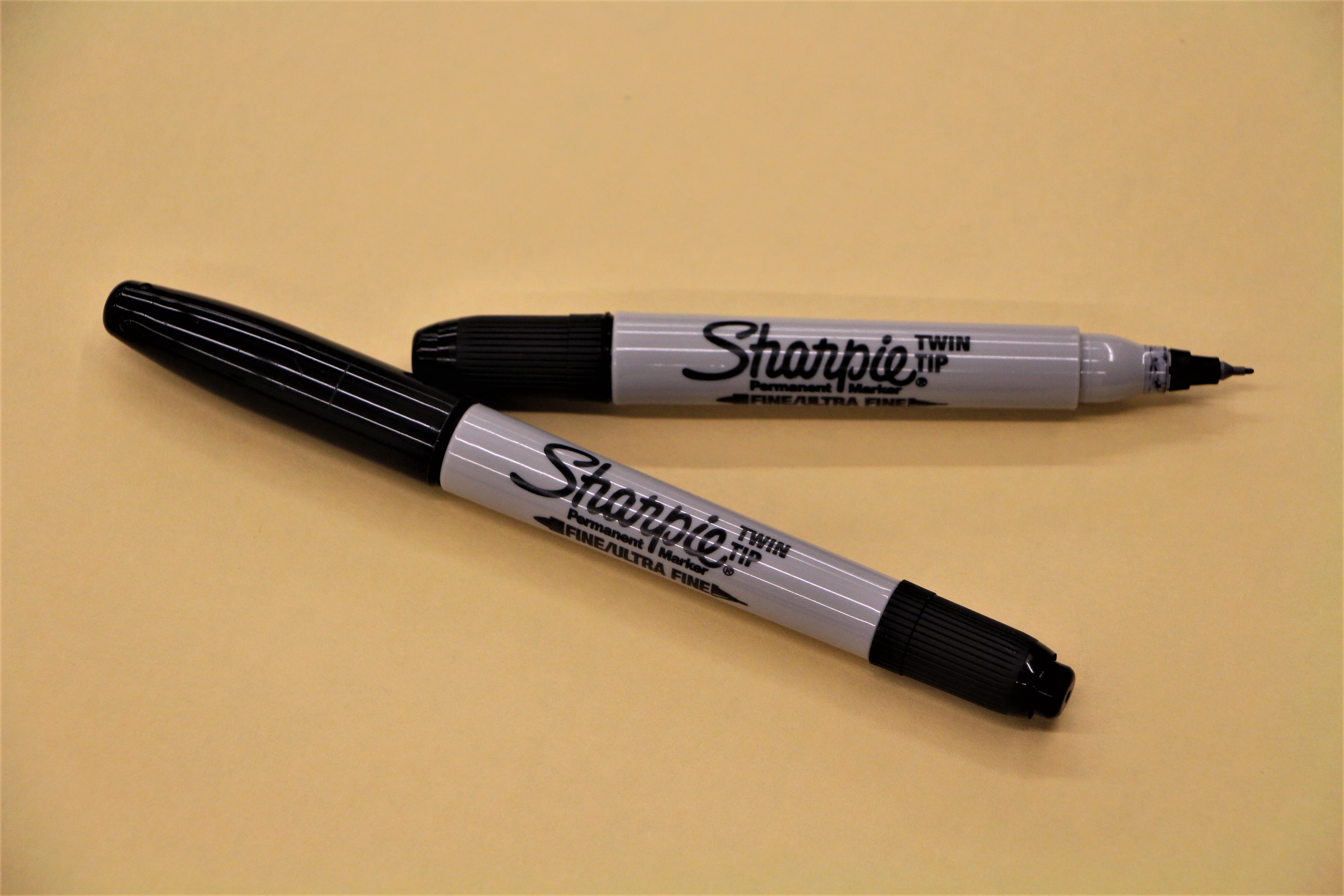
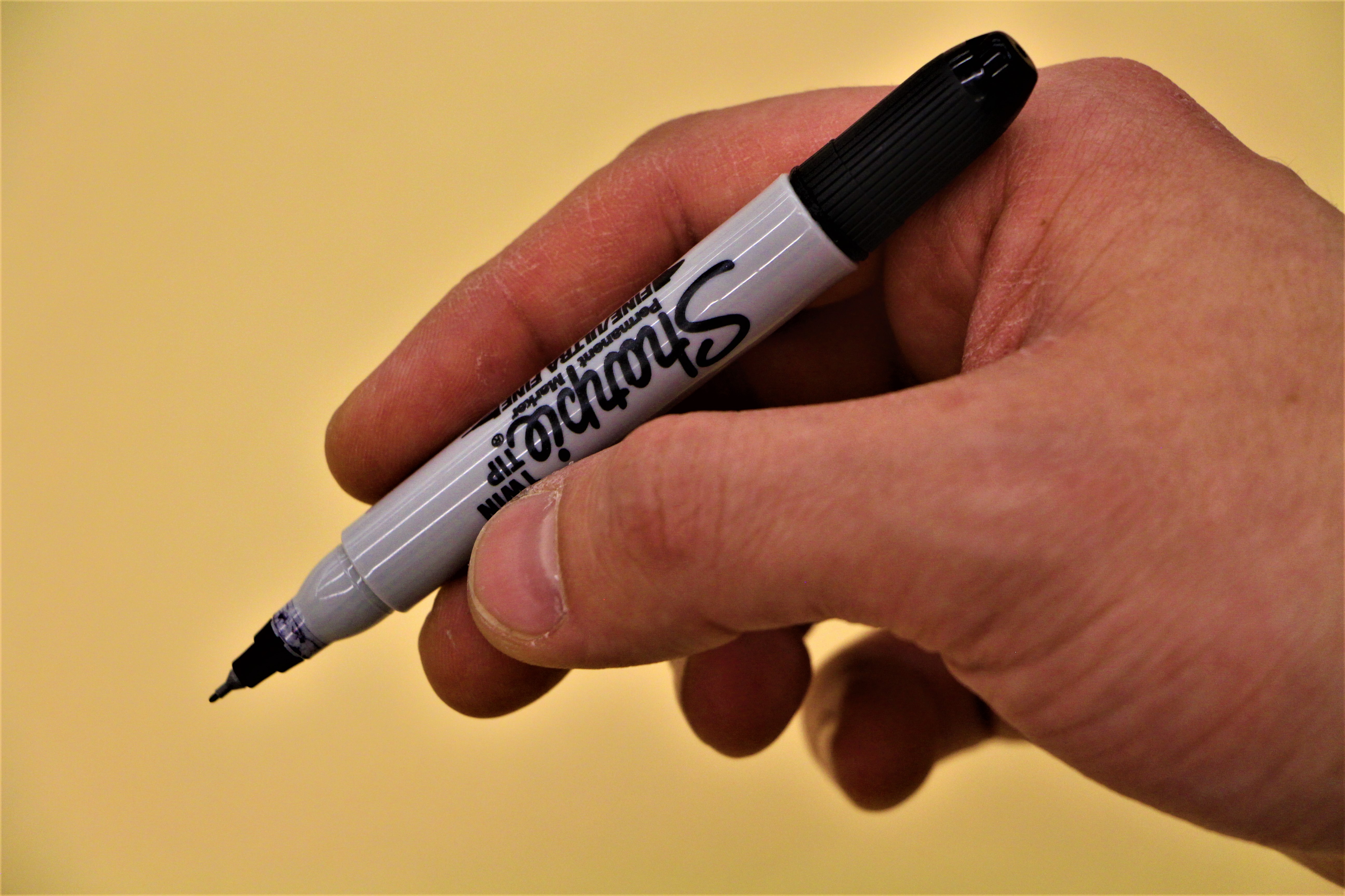
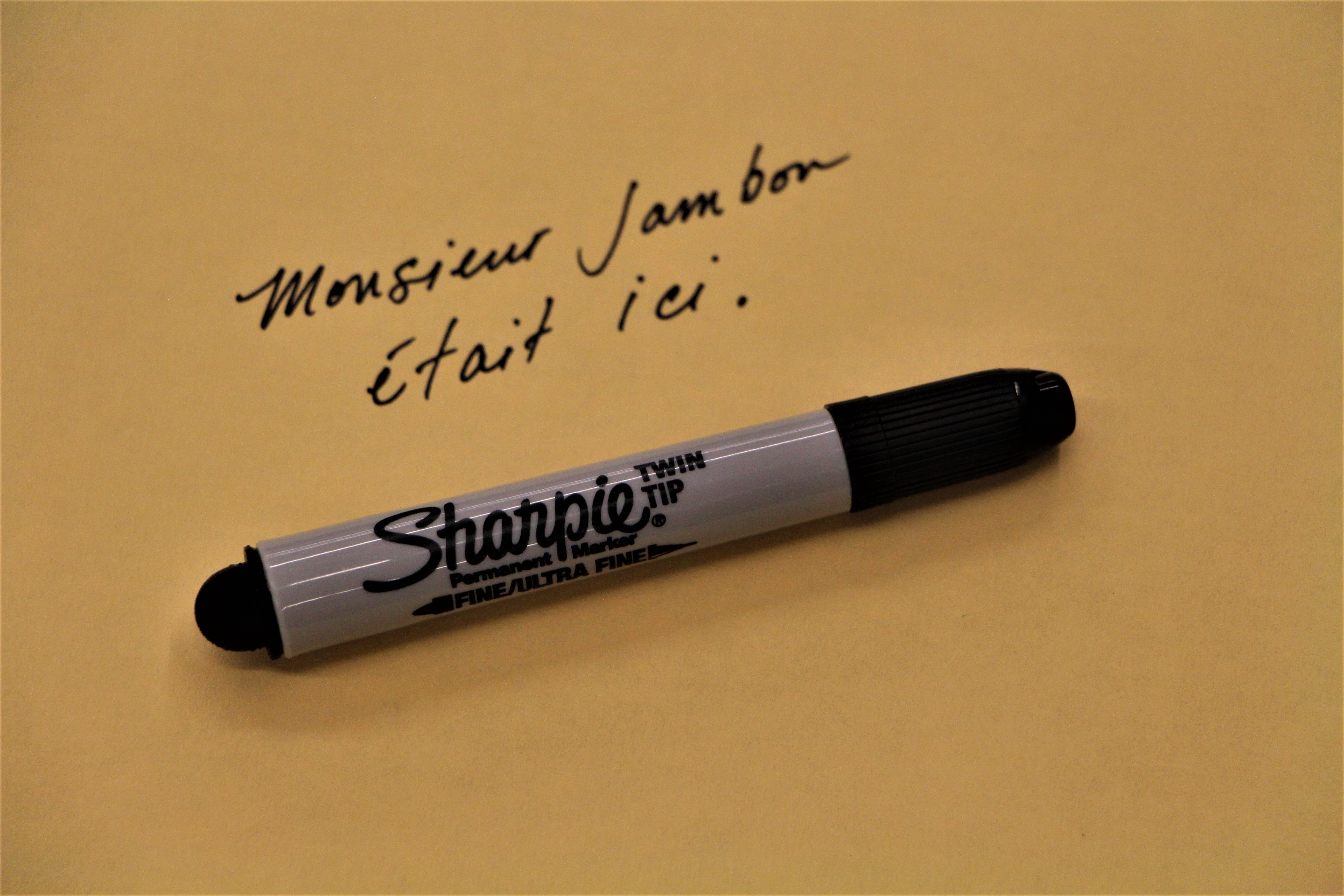
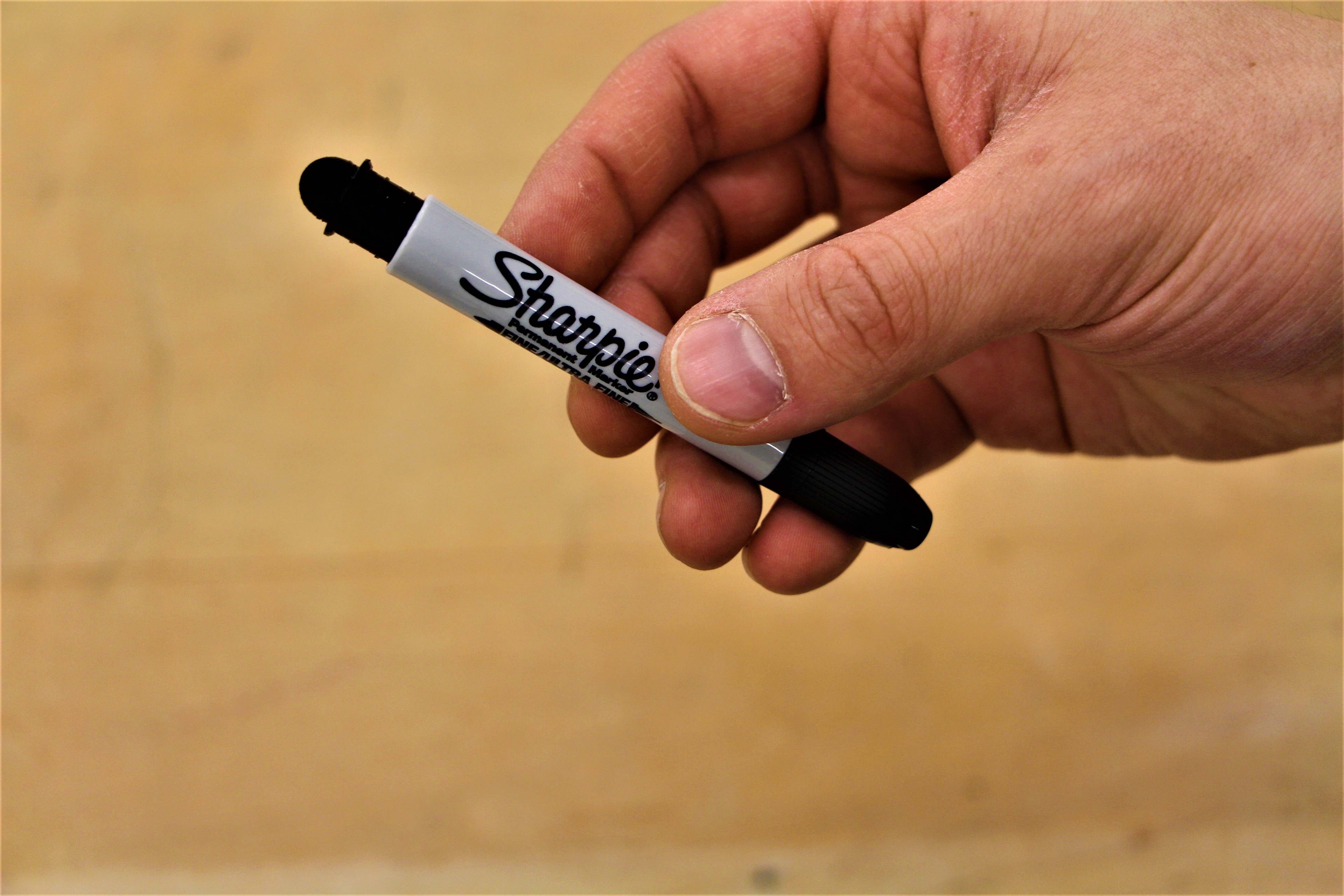
Disassemble a new Twin Tip Sharpie using the method explained in the first step and trim the cartridge carefully with either a utility knife (or pair of scissors in a pinch) to approximately 65mm. Reinsert the cartridge and press in the newly 3D printed piece. Voilà! A pocket-sized, Ultra Fine Sharpie that meets all of my criteria!
Cheers!
Mr. Ham.