Ultra Compact Infrared Thermometer
by gokux in Circuits > Gadgets
7635 Views, 163 Favorites, 0 Comments
Ultra Compact Infrared Thermometer

My Ultra Compact LiDAR Distance Meter/Range Finder project was a great success, and many people loved the cute design. It is kind of a follow-up project of that. What if we swap that LiDAR with an infrared temperature sensor? The result is a cute tiny infrared thermometer with -70 to 380 °C temperature range
Now let's go through how i built it
Supplies
.jpg)
Parts
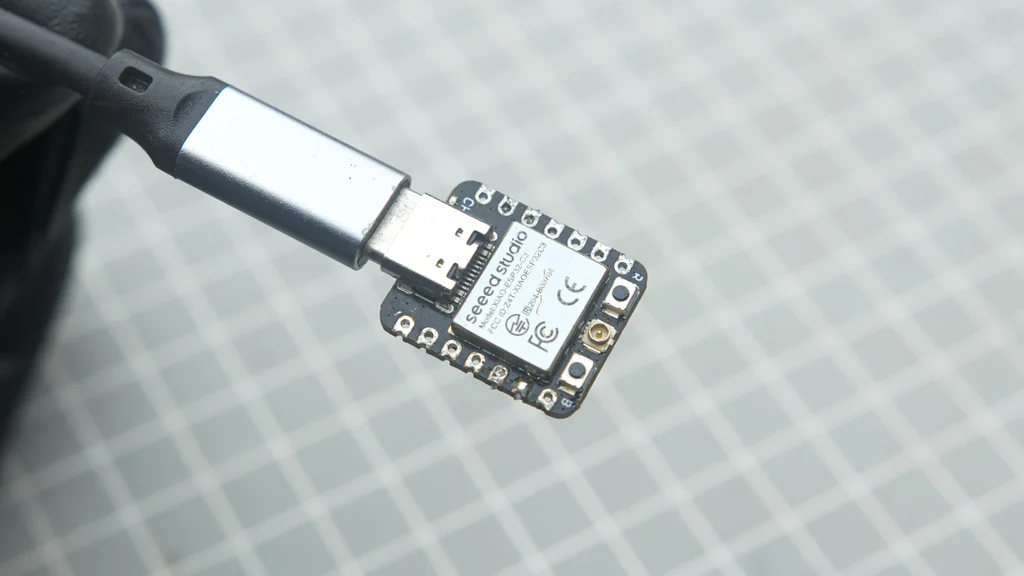
- Seeed studio xiao esp32c3
- Micro battery
- 0.49inch OLED Display Module
- GY906 MLX90614ESF-BAA Contactless Temperature Sensor
- Slide switch
- B-7000 multi-Purpose glue
- 30 AWG wires
Tools
- Soldering iron kit
- Wire cutter
- Third-Hand Soldering Tool
Designing in Autodesk Fusion 360
I utilized Fusion 360 to plan and design my project, which required careful space optimization. I needed to fit all the parts into the smallest form factor possible while ensuring practicality, including sufficient space for wiring and easy assembly. First, I imported all the 3D models of the parts and tried different configurations by placing the parts in various positions. Once I found the optimal configurations, I built the enclosure around them. All design files are provided below.
Downloads
3D Printing
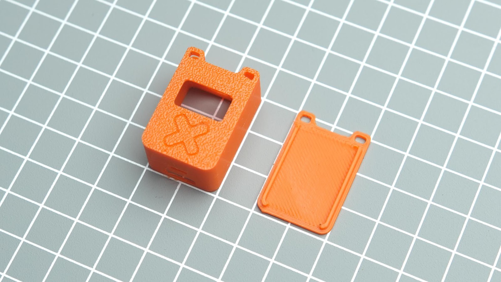
After exporting all the models into.STL files, I 3D printed them using my Anycubic printer. For this project, I used Numakers PLA+ Outrageous Orange filaments. You can find the.STL files from step one.
Flashing Code to Xiao ESP32C3
I always like to upload the code to the microcontroller before assembly. I am using Arduino IDE to flash the code. follow these tutorials for setting up IDE for Seeed Studio XIAO esp32c3 and learn more about this board
Please download and install the Adafruit_MLX90614.h library before compiling
How to install library tutorial video link
After this, I connected Xiao to a USB and flashed the program
#include <Wire.h>
#include <Adafruit_MLX90614.h>
#include <Adafruit_GFX.h>
#include <Adafruit_SSD1306.h>
#define SCREEN_WIDTH 128 // OLED display width, in pixels
#define SCREEN_HEIGHT 64 // OLED display height, in pixels
#define OLED_RESET -1 // Reset pin # (or -1 if sharing Arduino reset pin)
Adafruit_SSD1306 display(SCREEN_WIDTH, SCREEN_HEIGHT, &Wire, OLED_RESET); //Declaring the display name (display)
Adafruit_MLX90614 mlx = Adafruit_MLX90614();
void setup() {
mlx.begin();
display.begin(SSD1306_SWITCHCAPVCC, 0x3C); //Start the OLED display
display.clearDisplay();
display.display();
}
void loop() {
  float obTemperature = mlx.readObjectTempC();
  display.clearDisplay();
  display.setTextSize(2);
  display.setTextColor(SSD1306_WHITE);
  display.setCursor(37, 35);
  display.print(obTemperature);
  display.setTextSize(1);
  display.setCursor(45,55);
  display.print("CELSIUS");
  display.display();
  delay(500);  // Update every second
}
Wiring Diagram
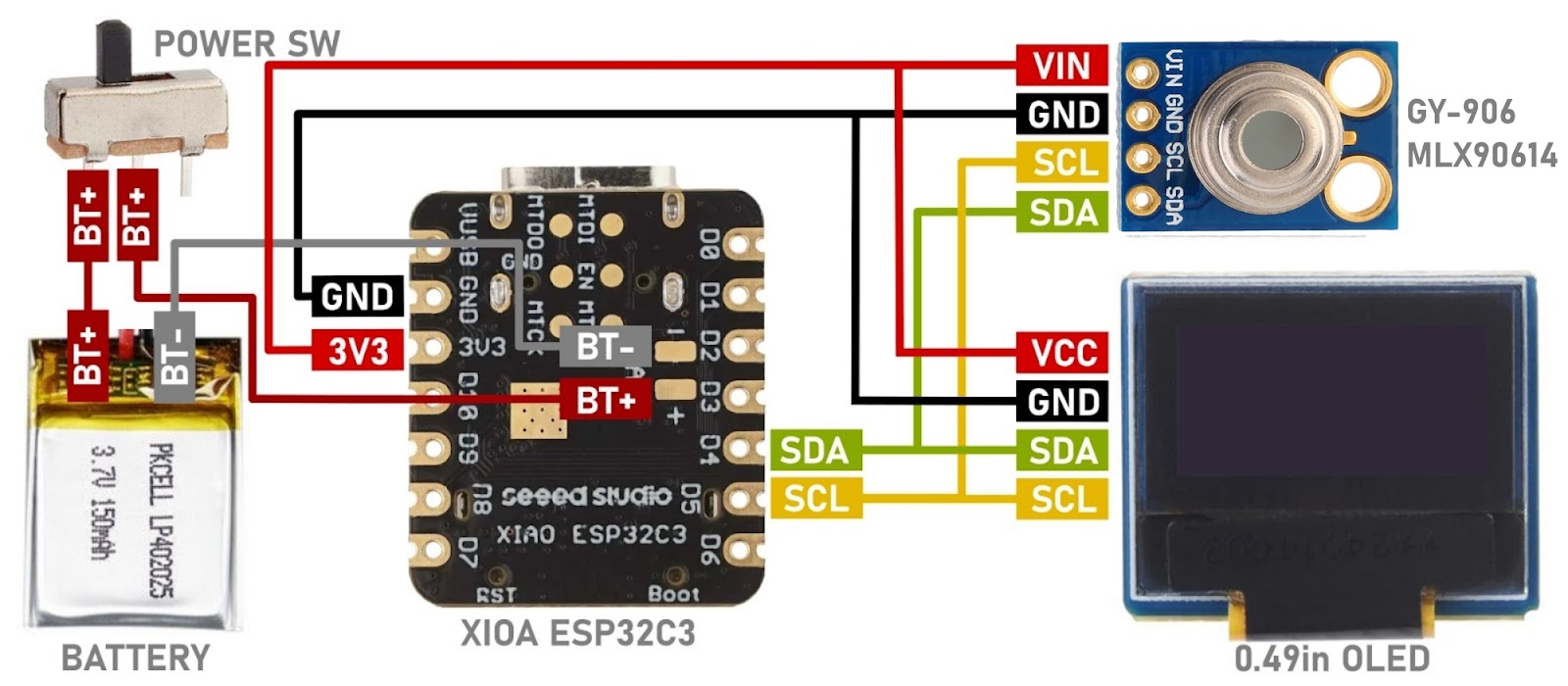
XIAO ESP32C3 Supports lithium battery charge and discharge management. Which means BMS is built in . So there is no need for an external BMS. You can charge the battery through a USB port
Assembly and Wiring
Due to the small size of our project, we need to use a different approach for assembly. Since we don't have any screw holes on the parts, we can't use tiny screws to hold everything together. The best method to use is glue, which is the same manufacturing method used in most compact tech products like the AirPods, for example. We are not using hot glue here, we are using a B-7000 multi-purpose glue. Now let's start the assembly
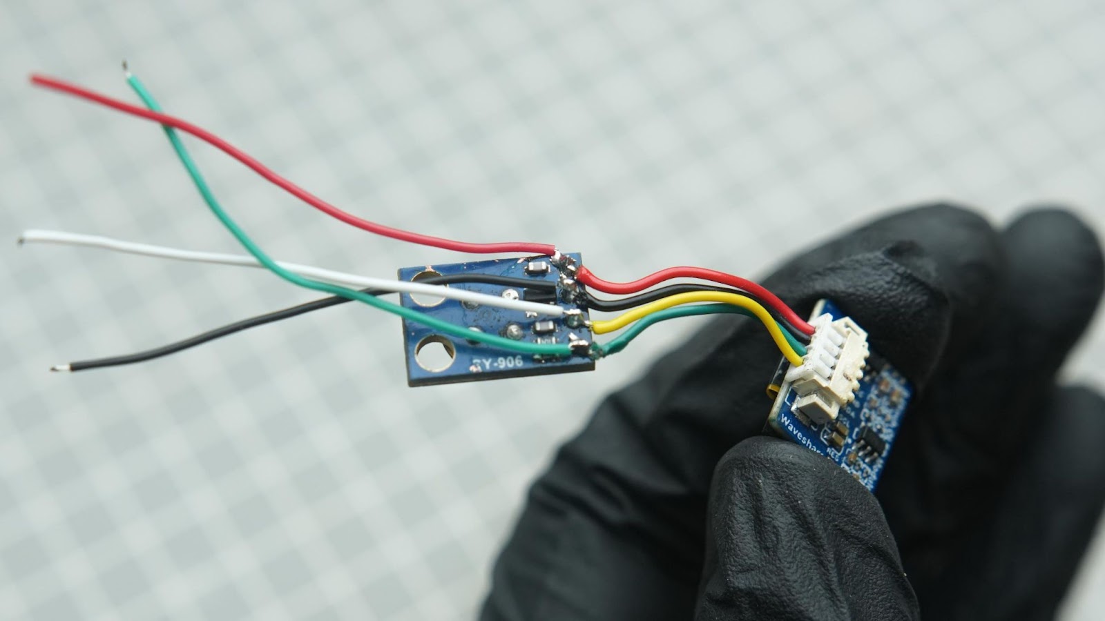
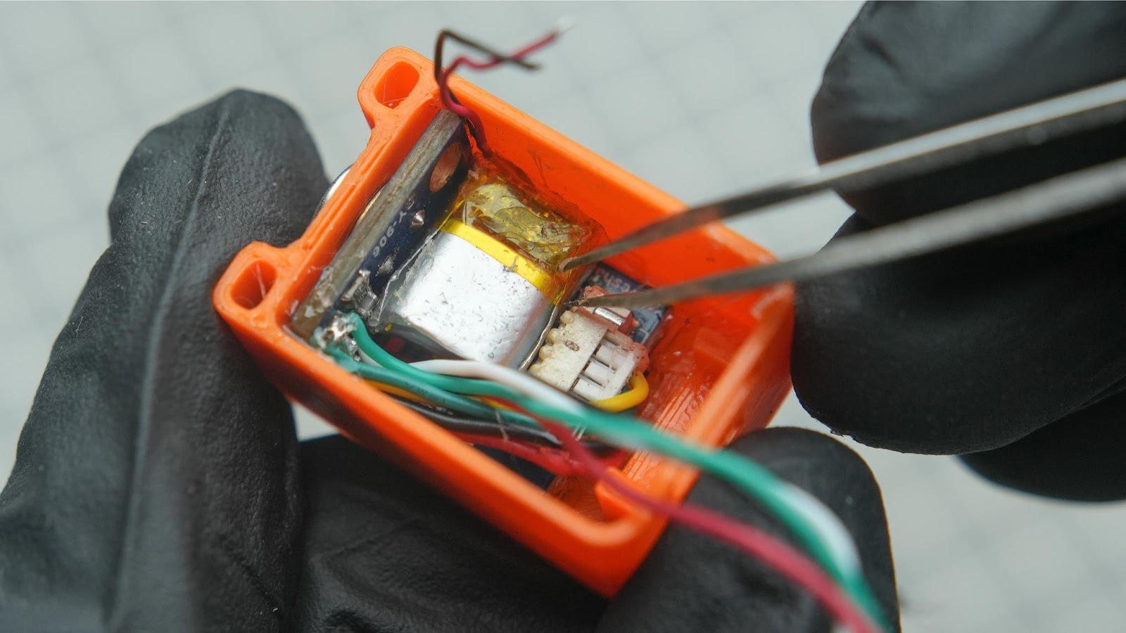
Step 5.1
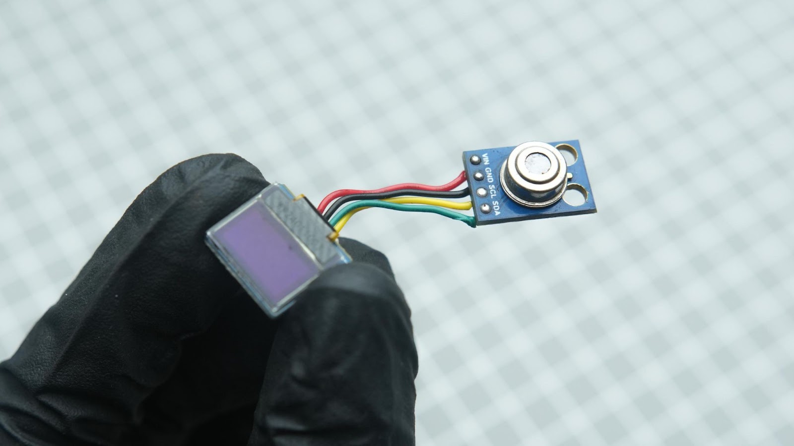
Solder all four wires from the OLED module to the sensor. Also, solder another four 20mm wires from the sensor that will be used to connect to xiao GPIO during later steps.
Step 5.2
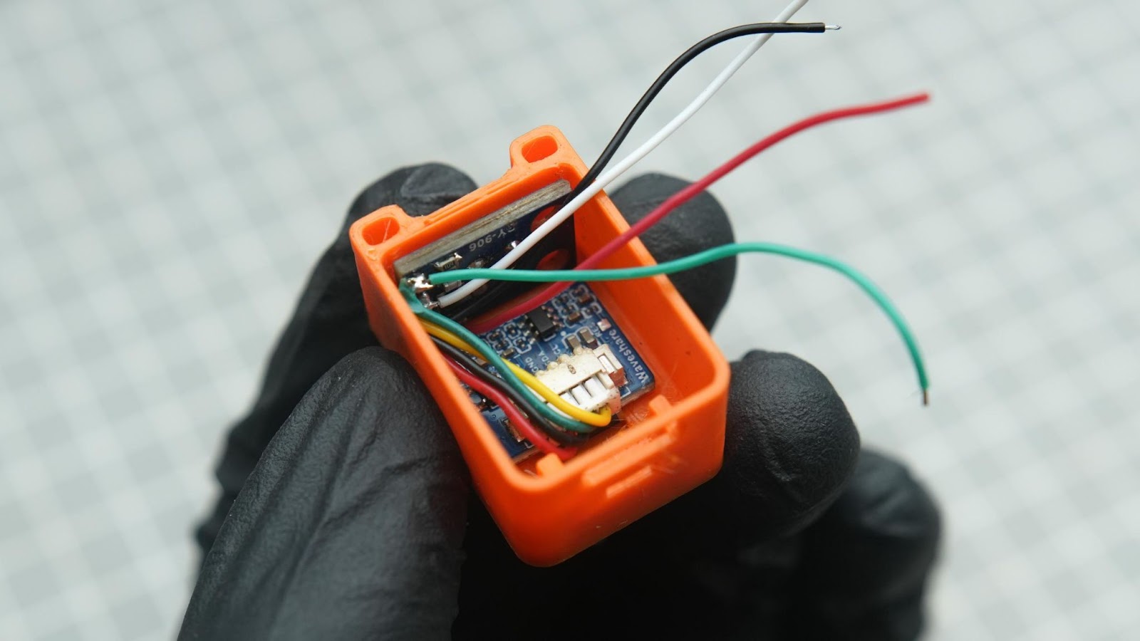
Place the OLED module into the 3d printed slot, also place the sensor on the side and make sure to align the sensor to the small window on the sides
Step 5.3
Now glue the OLED module and sensor. you apply glue on the sides of the modules
Step 5.4
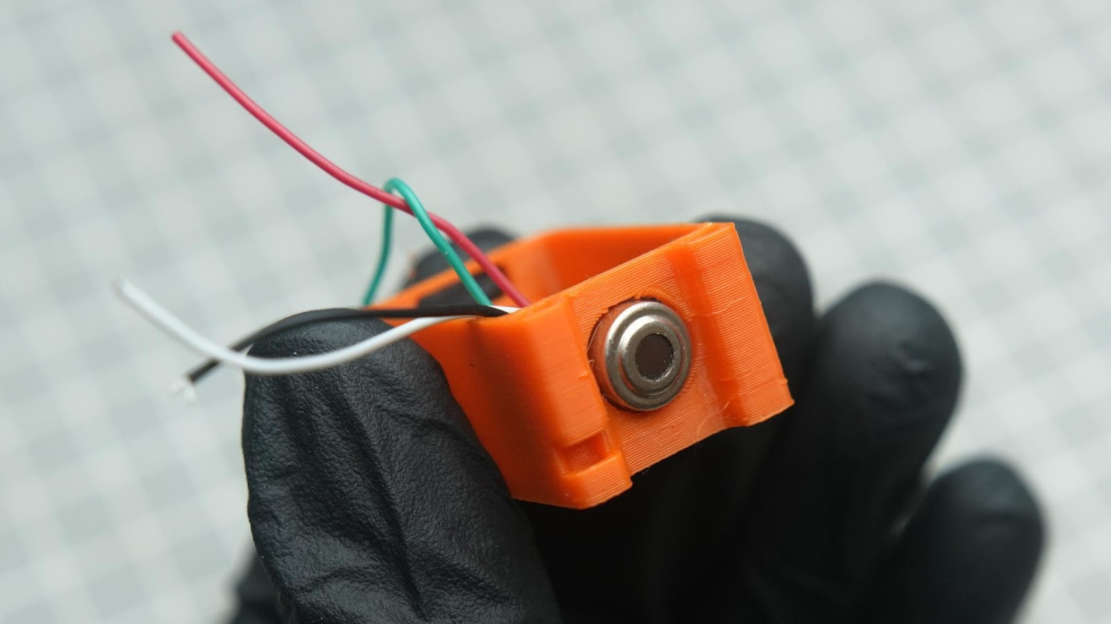
Glue battery on top of the OLED module
Step 5.5
Reduce the length of the switch terminals, cut the battery BT+ wire into the proper length and solder the BT+ wire into one of the switch terminals. Also, solder a small wire from the switch. which will be connected to BAT+ of the Xiao board
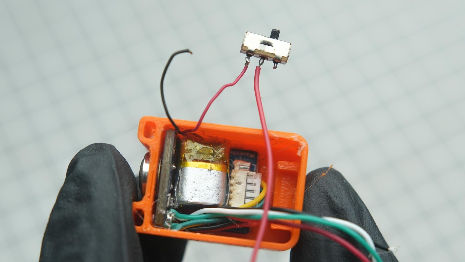
Step 5.6
Now place the switch into the 3d printed slot and glue it in place
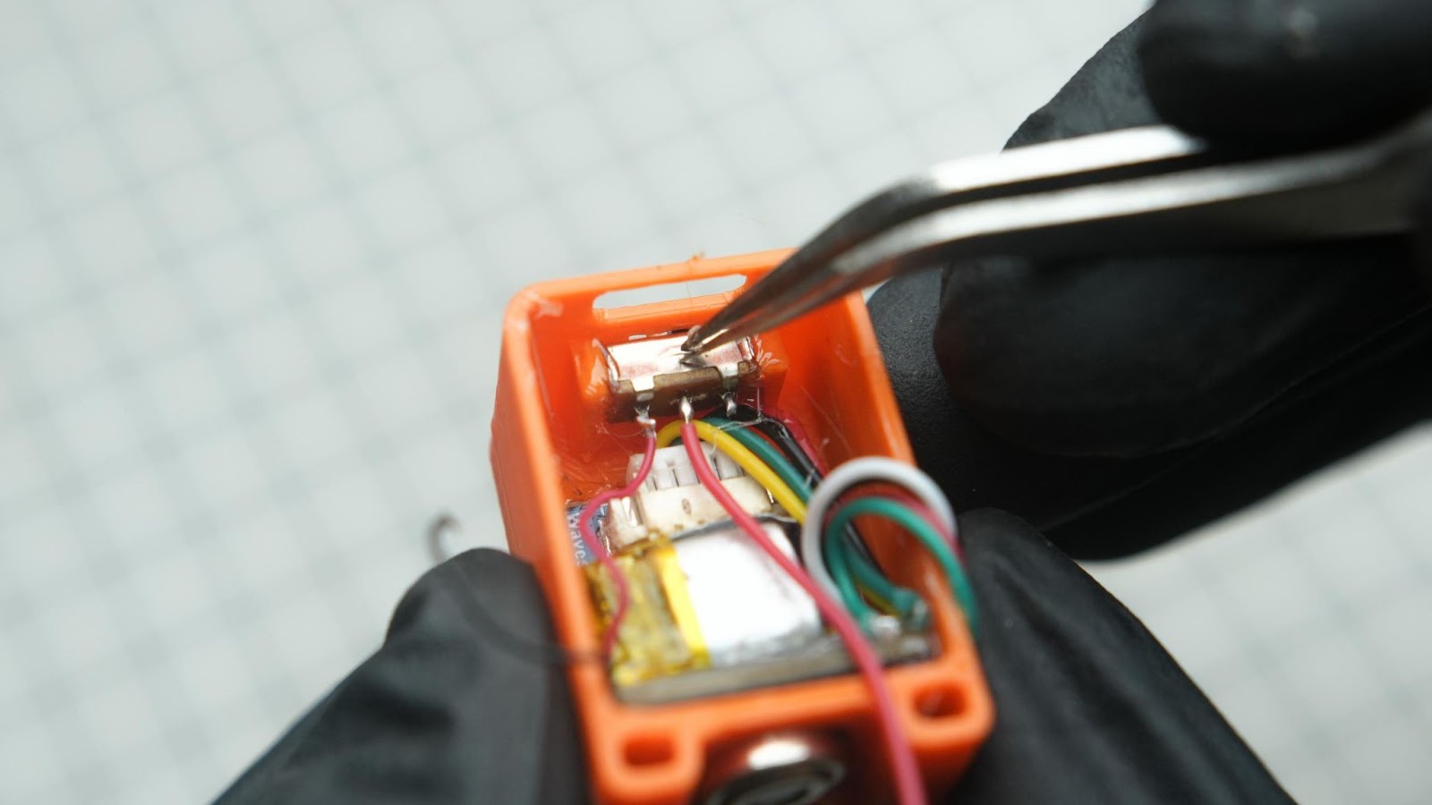
Step 5.7
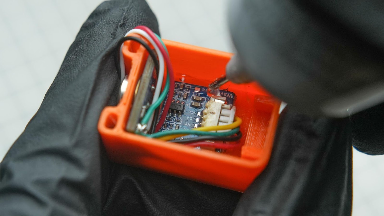
solder all GPIO wires underneath the Xiao board. Power the OLED and sensor through the 3V3 pin of the Xiao. Also, connect the negative battery wires and the positive BT wires from the switch to the battery terminals of the Xiao.
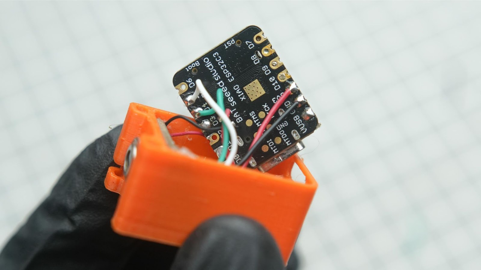
Step 5.8
Push down all the wires and place the Xiao board into the 3D print. Also, align the USB port with the hole on the 3D print. And glue the Xiao board
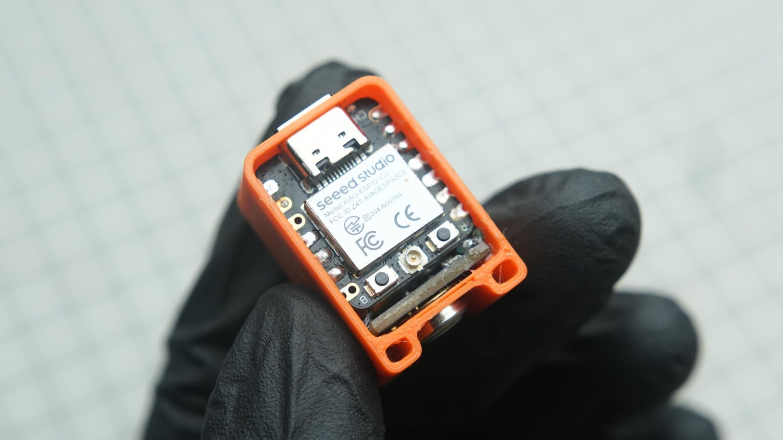
Step 5.9
Close down the back cap
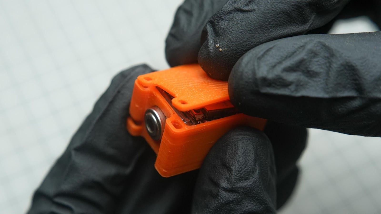
Yes !! we just completed the assembly of our project. Let's power it on
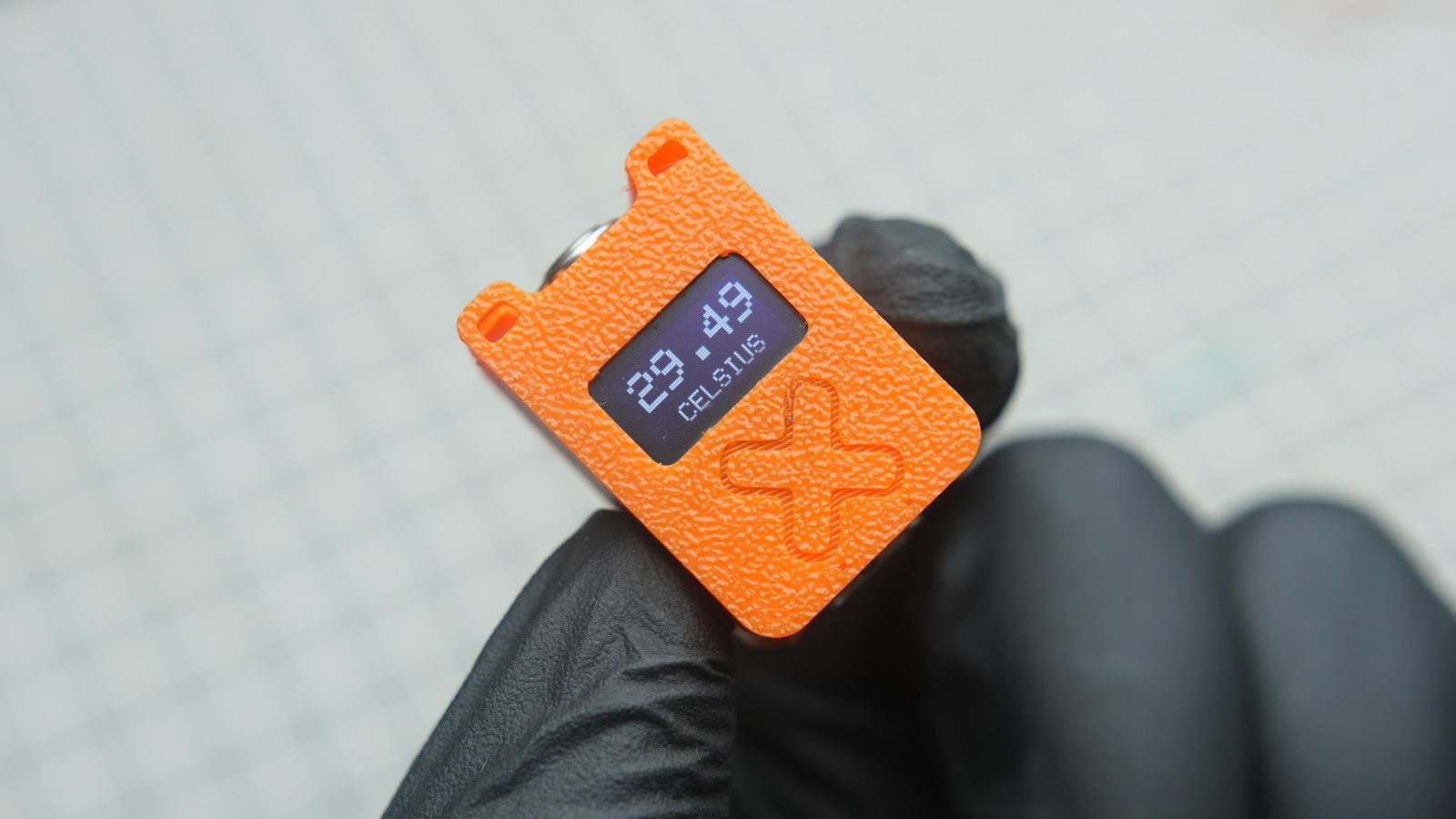
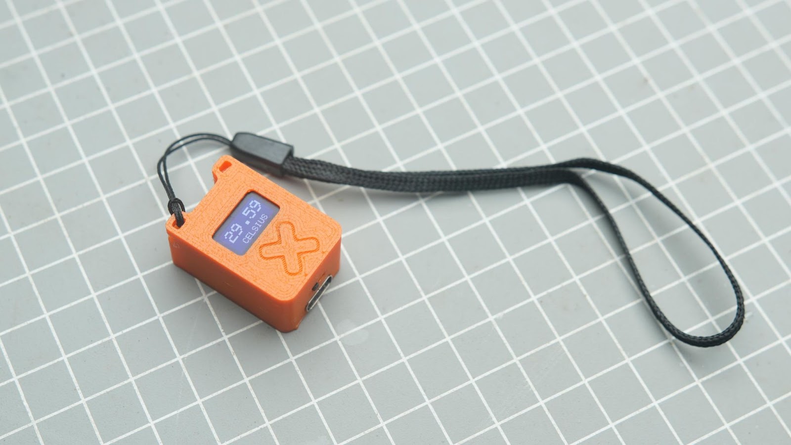
Yes, it works !!
You can use it as a keychain or add a small Lanyard to keep it handy
If you found this project helpful or inspiring, consider buying me a coffee ☕

It really helps me keep building and sharing more open-source projects.
https://buymeacoffee.com/gokuxmaker