USS Enterprise Using 123D Make
by 86 in Workshop > Laser Cutting
9157 Views, 34 Favorites, 0 Comments
USS Enterprise Using 123D Make
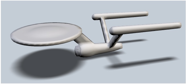
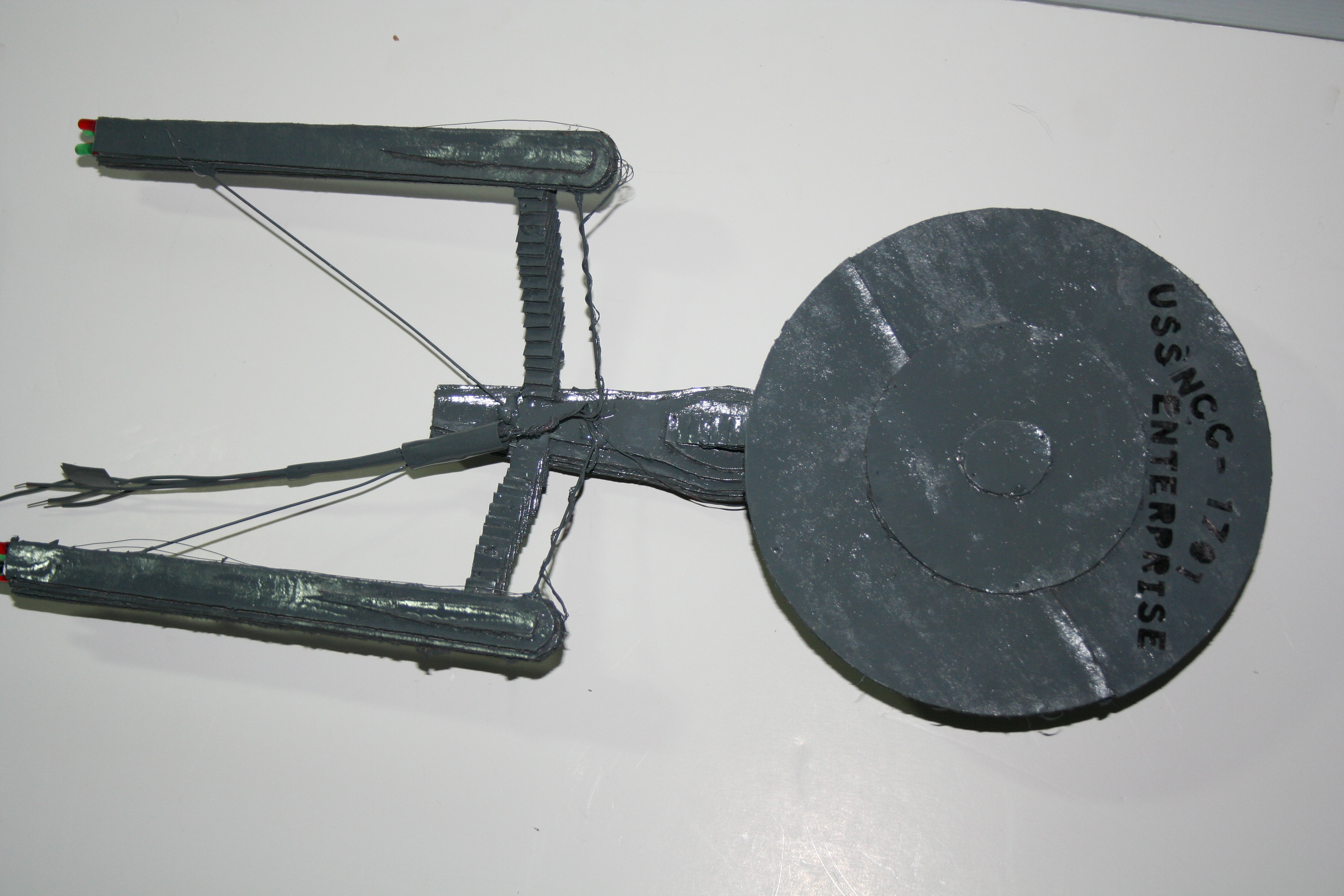
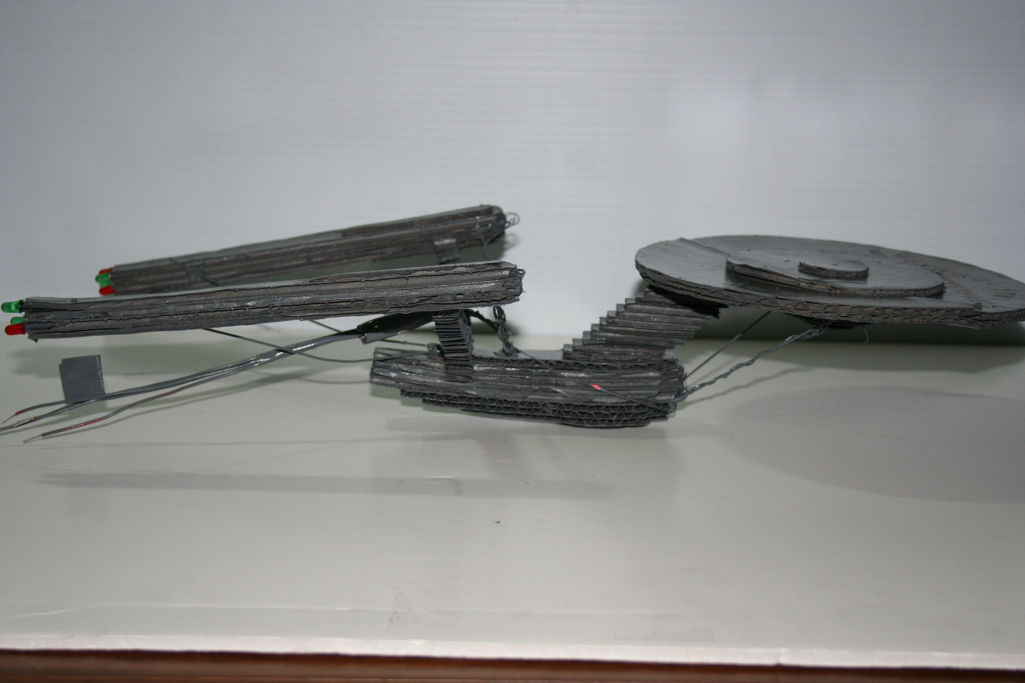
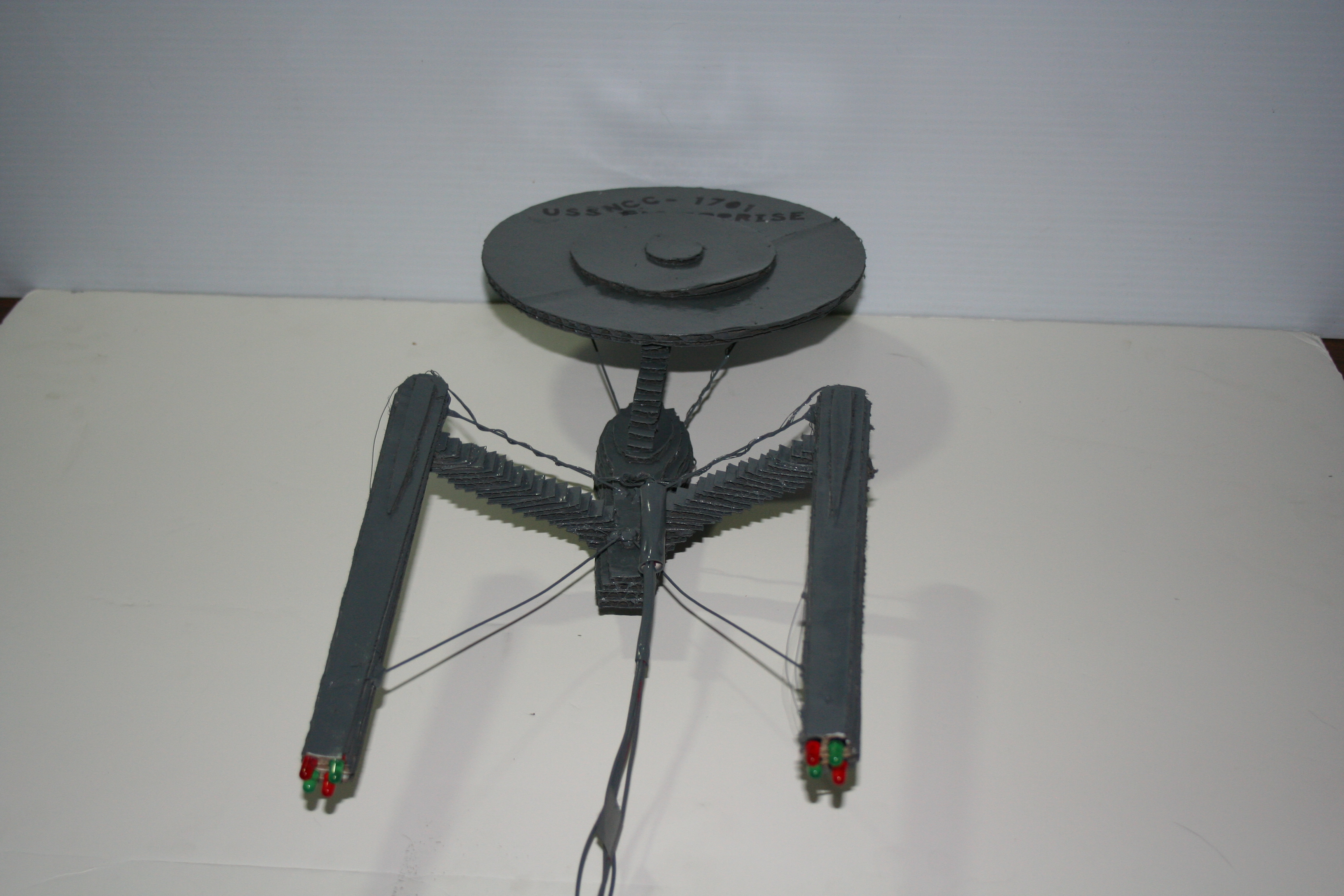
What did you make?
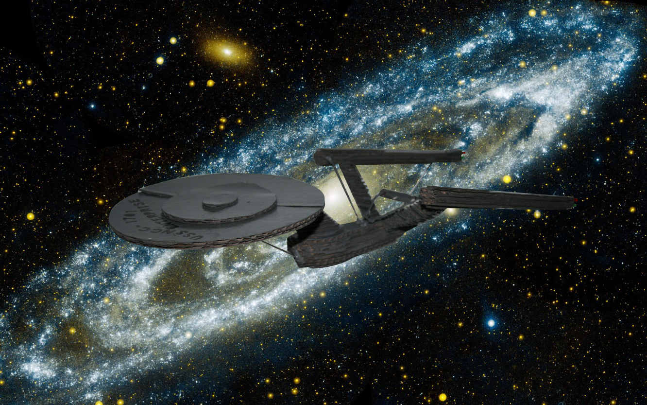
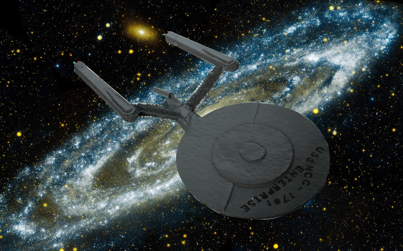
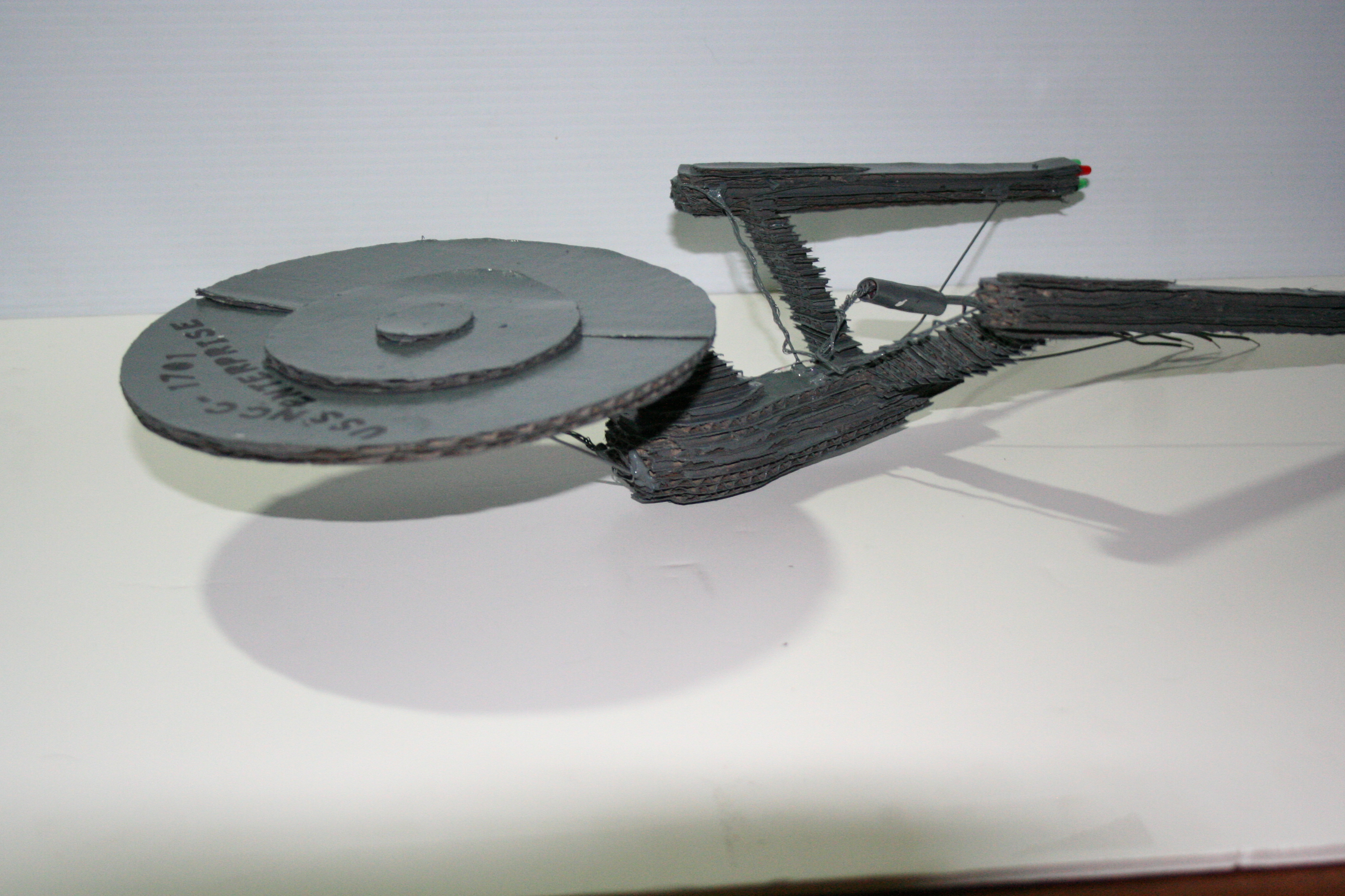
I made a cardboard model of the USS Enterprise from Star Trek using 123D Make. It has blinking lights powered by an arduino. See the photo because a picture is worth a thousand words. Once painted,
abelled and suspended n Space, it looks almost like the real thing!
How did you make it?
I have made another similar Instructable project.- the 123D Space Shuttle. I chose the Enterprise for this project because I watch Star Trek and I like the shape of the ship.
Where did you make it?
I designed and built it on my own at home in the garage.
What did you learn?
I leaned how to design models in 123D Design as well as arduino programming. I also learned how to safely use an Xacto knife. Next time I would like to use a laser cutter.
Tools and Matirals
Materials
- Cardboard
- Wheat Paste
- 4X 5mm Red LED
- 4X 5mm Green LED
- 2X Super Bright 5mm Red LED
- Arduino Uno and Arduino IDE
- Breadboard
- Solder
- 22 awg Hook Up Wire
- 30 awg Magnet Wire
- 12 awg Wire
- Electrical Tape
- 123D Make
- Laser Cutter or
- Hobby Knife and Printer
- Soldering Iorn
- Wire Strippers
- Hot Glue Gun
Using the Software

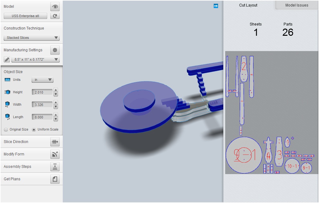

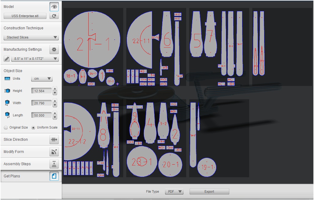

First, download and extract the zip file, if you want to change the size from 50 cm, open 123D Make file in the zip file. Next, make sure that uniform scale is selected and then change the dimensions to the desired size. After that click the "get plans" button and select file type, then click Export.
Downloads
Cutting
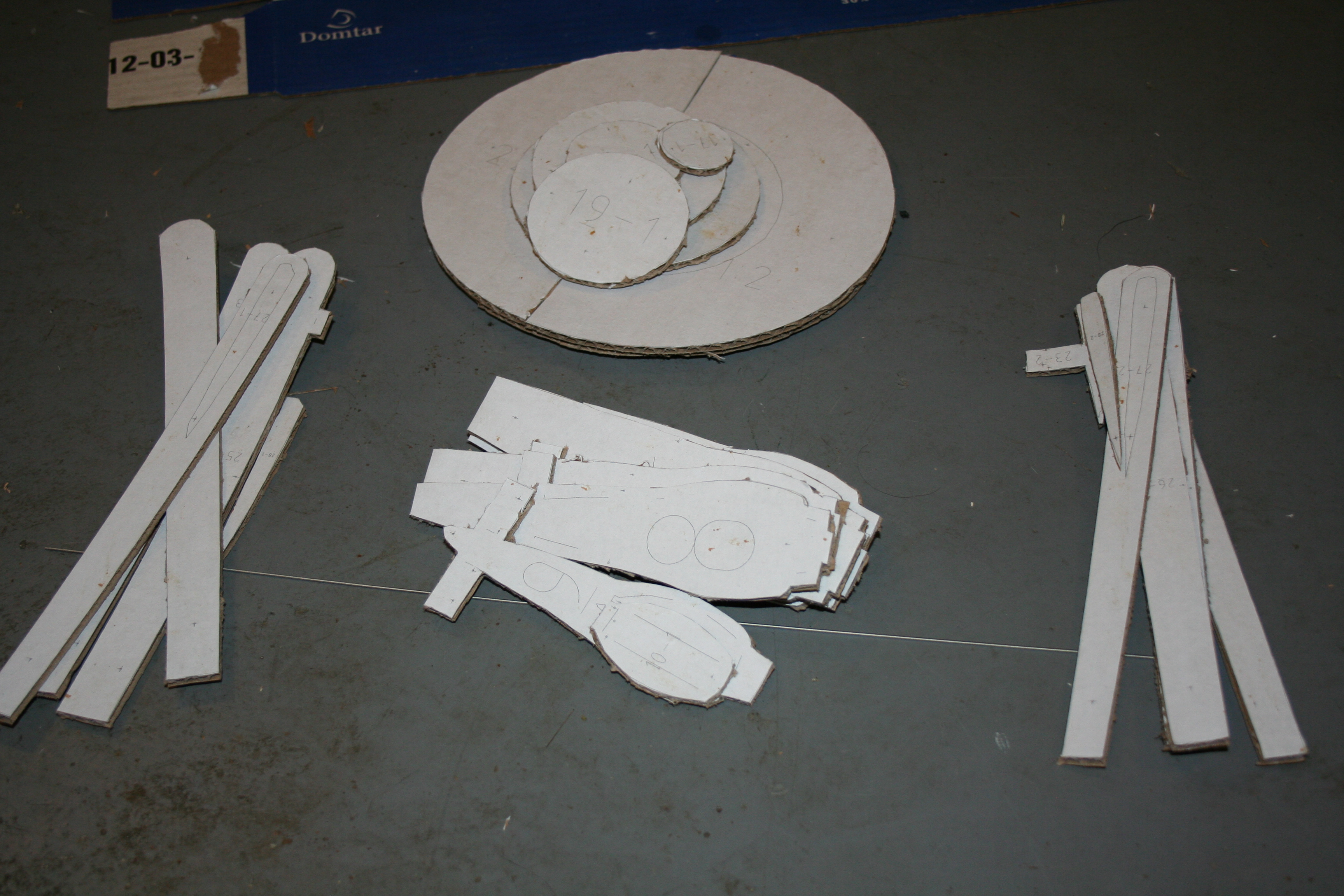
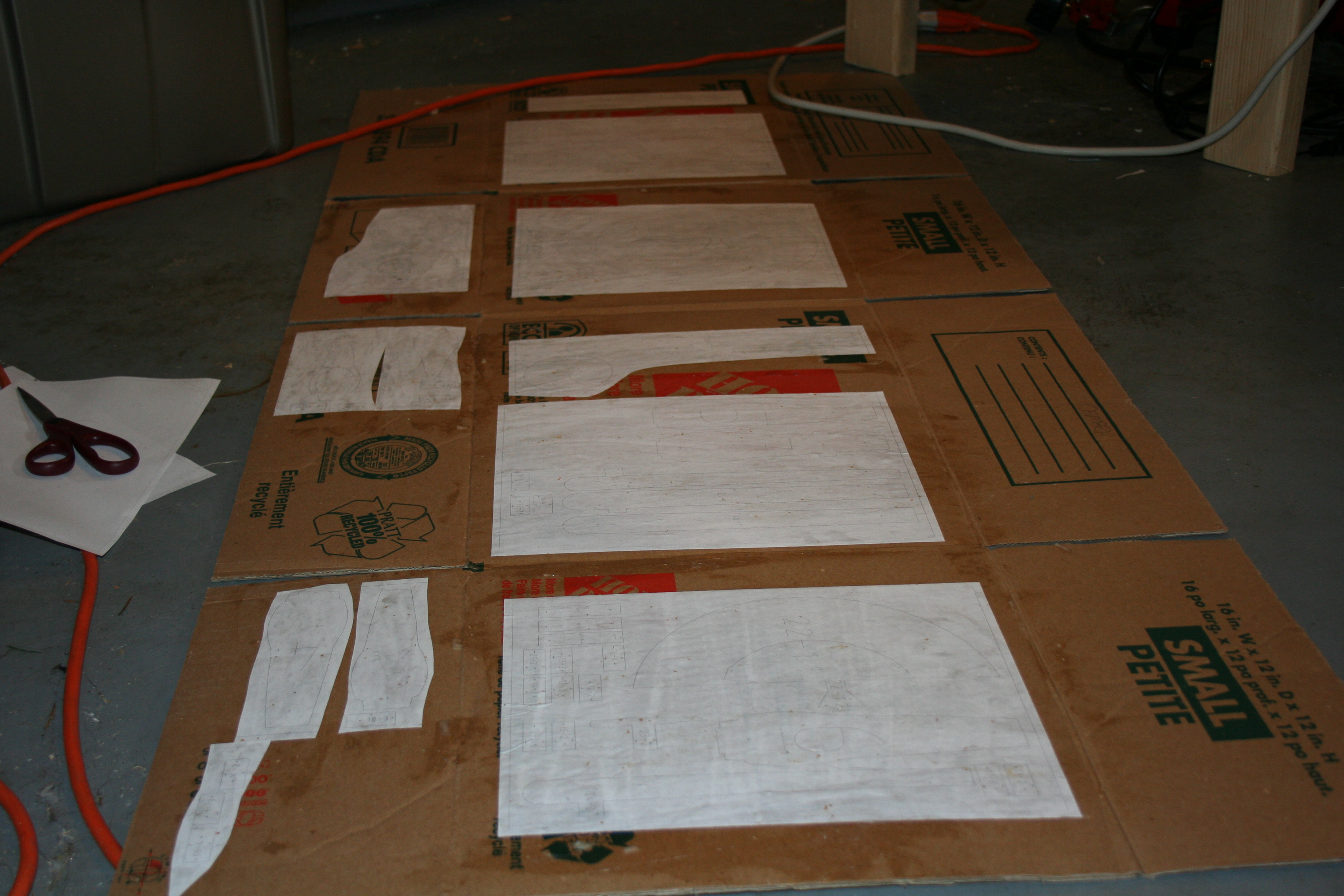
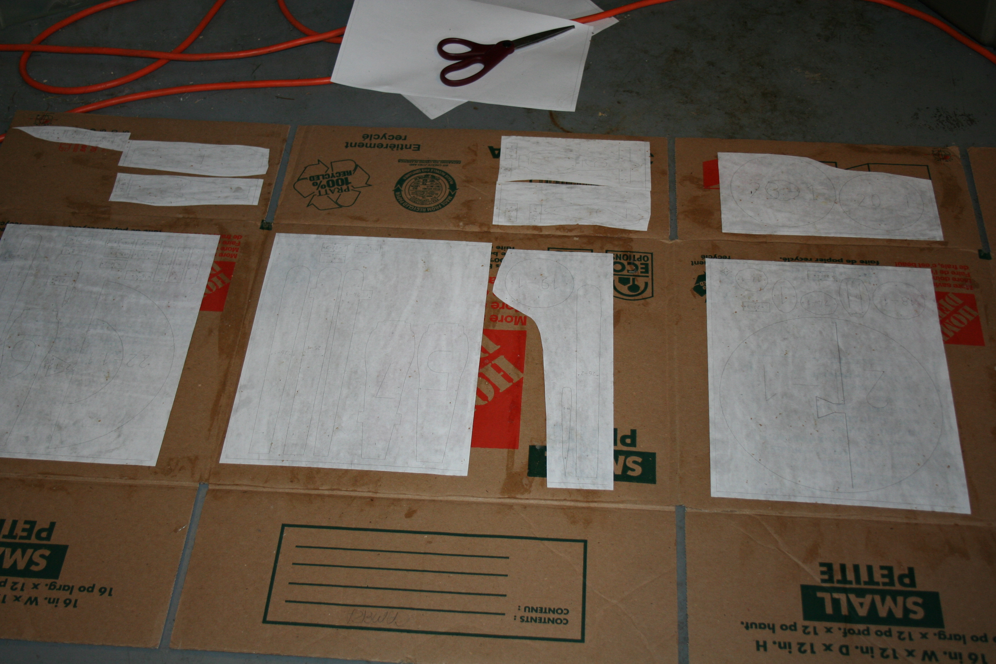
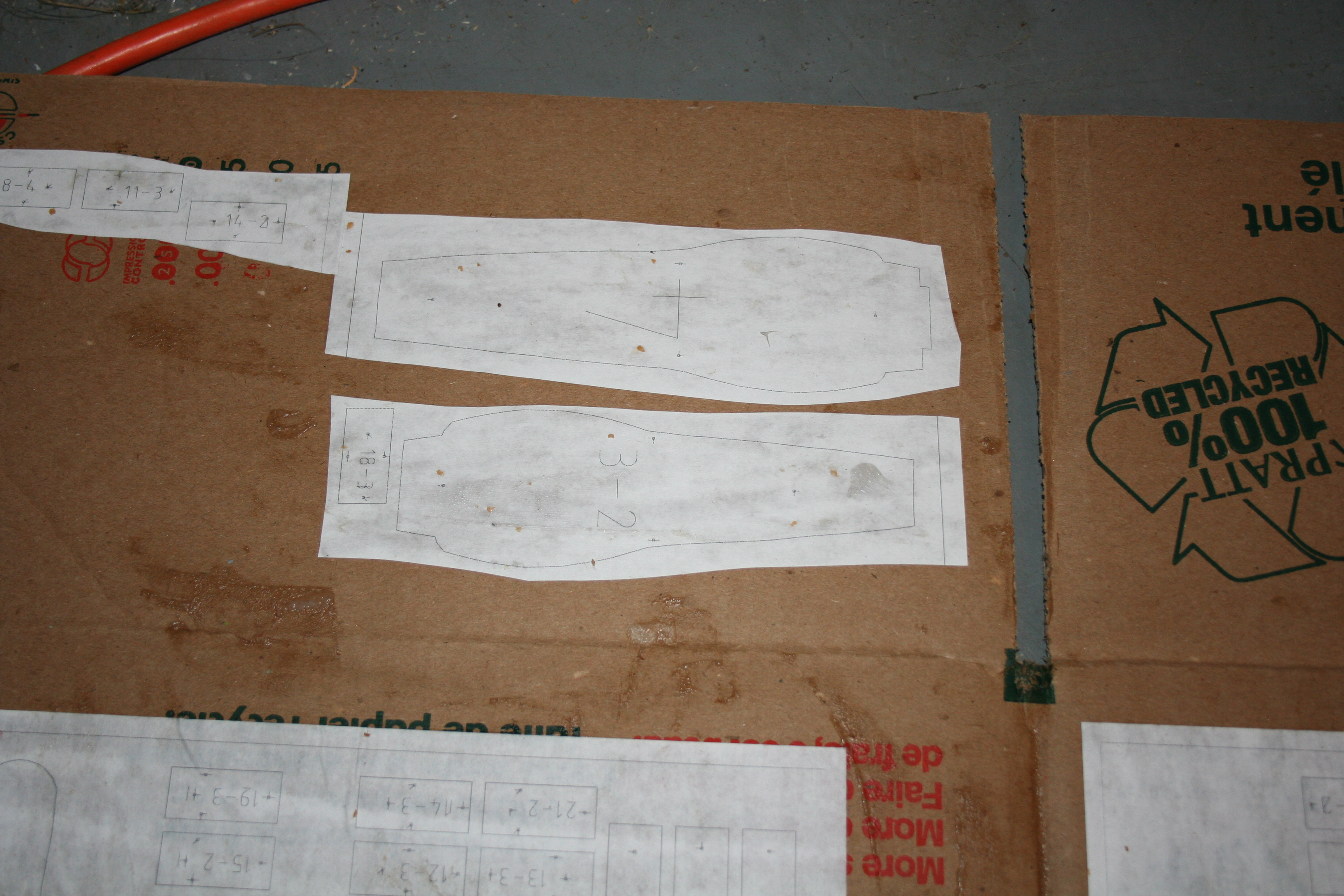
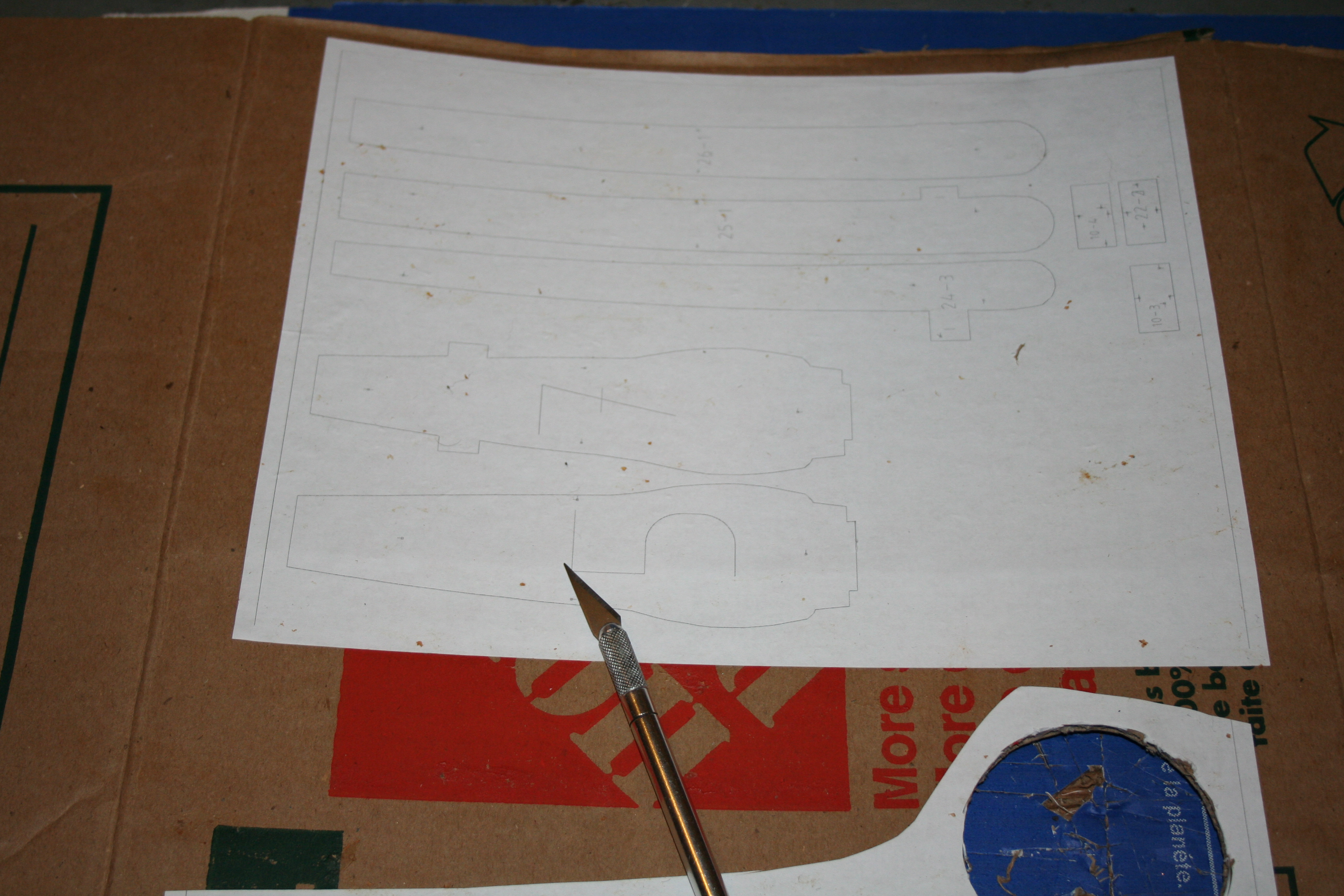
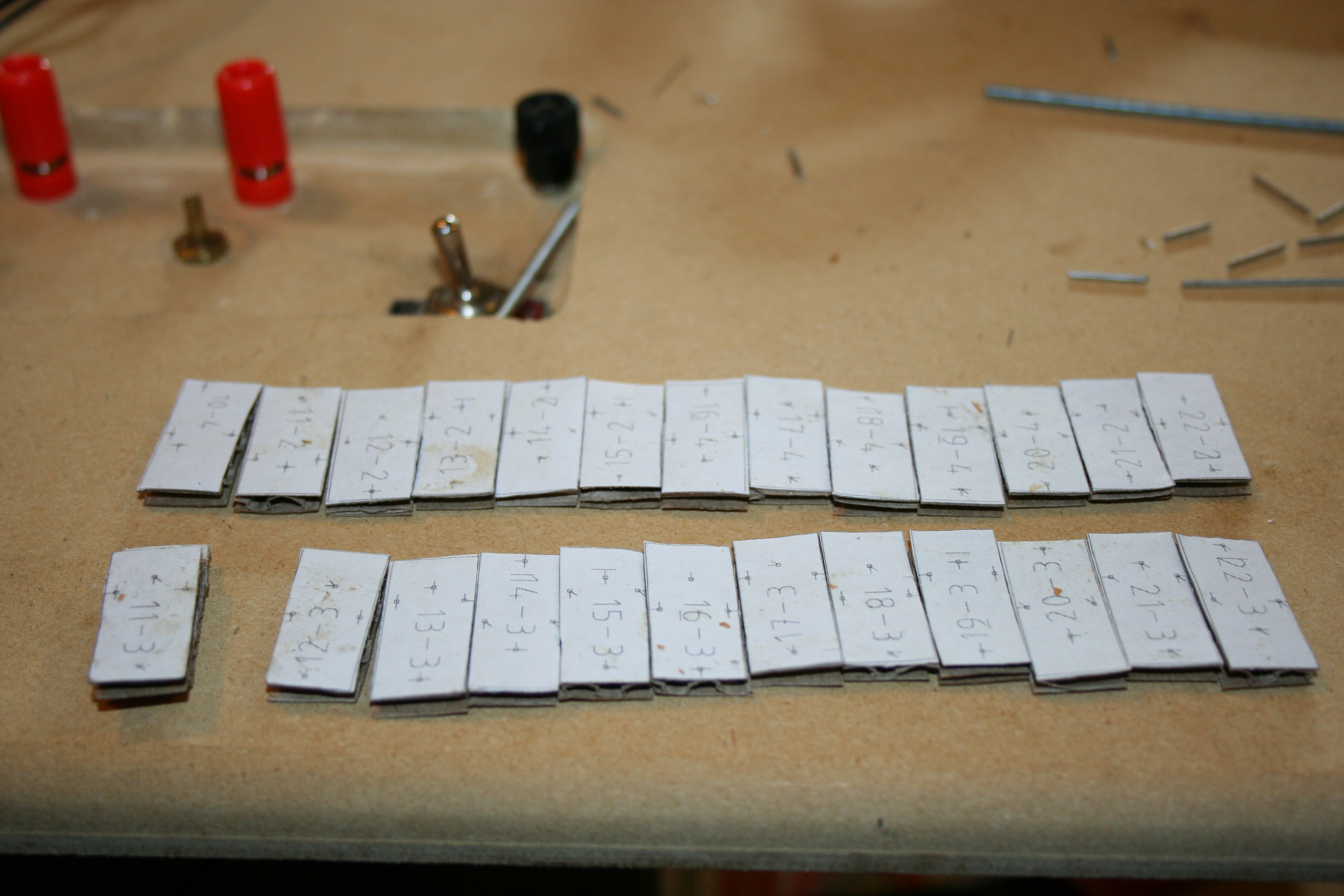
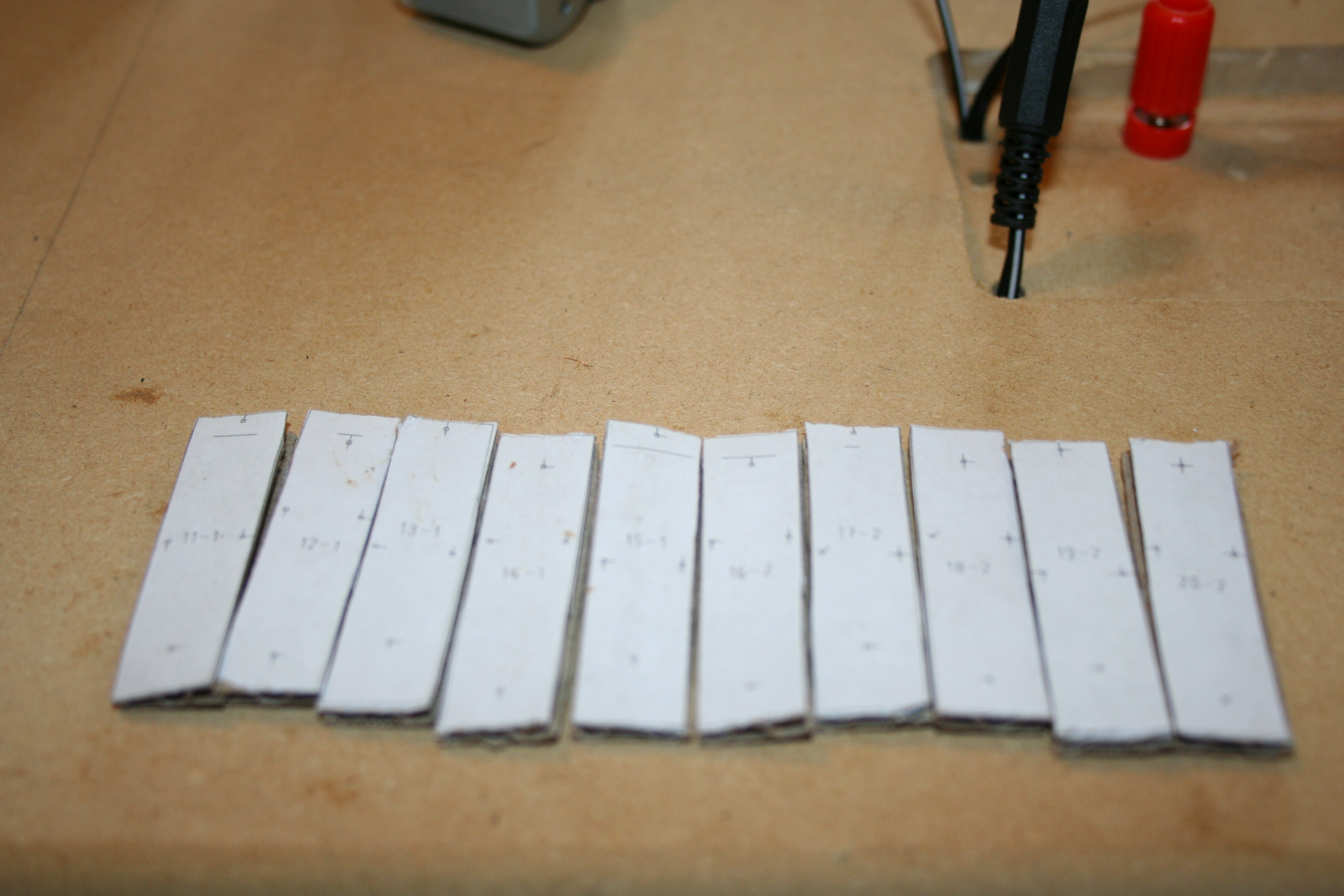
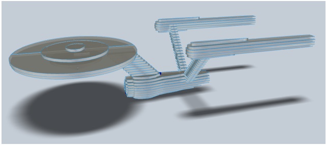
If are you are using a laser cutter set it so that it cuts through on the blue lines and just etches the red lines. If you are hand cutting, print out the pdf and glue them to cardboard with wheat paste, then cut them out with the hobby knife.
Gluing
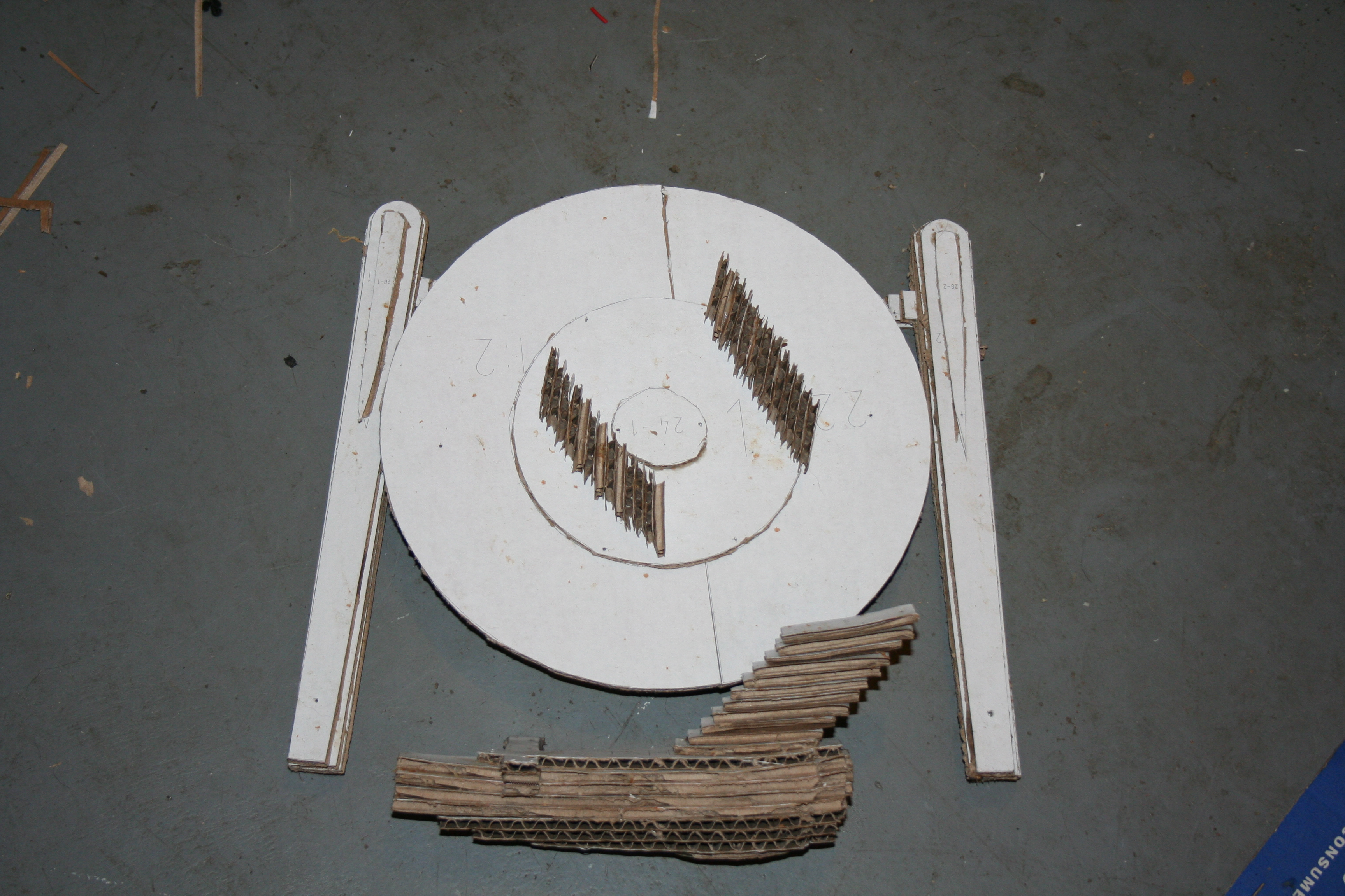
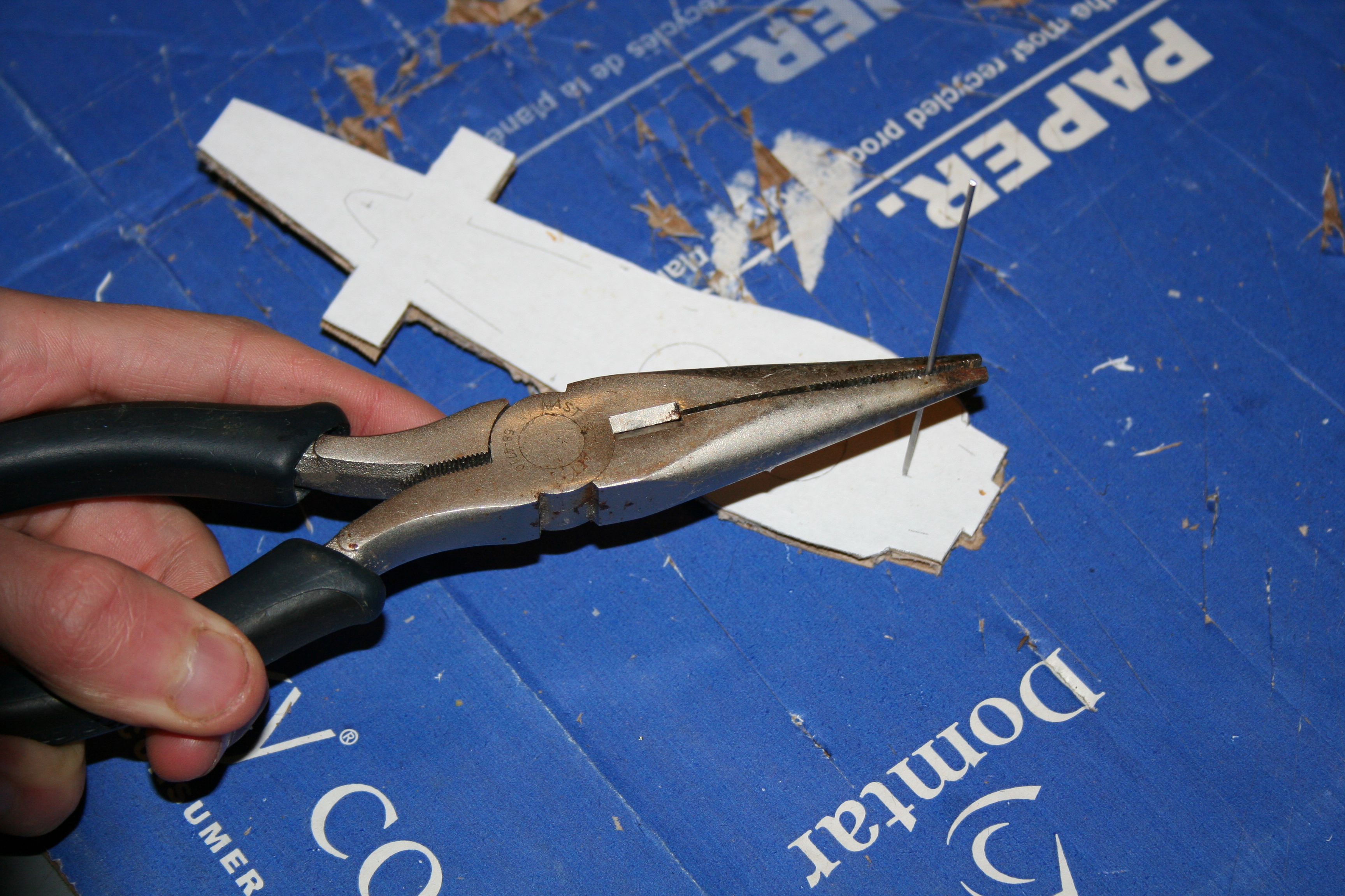
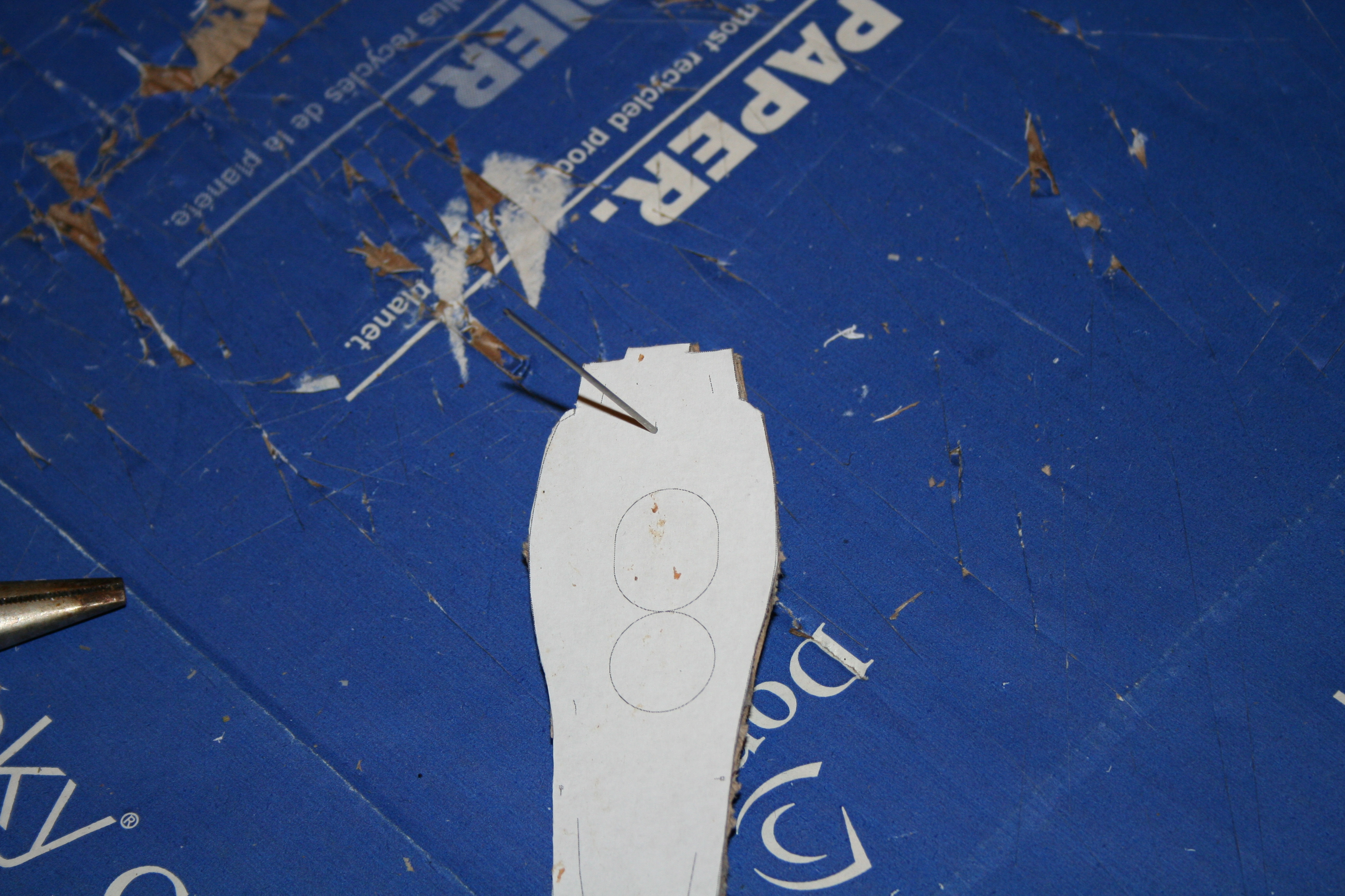
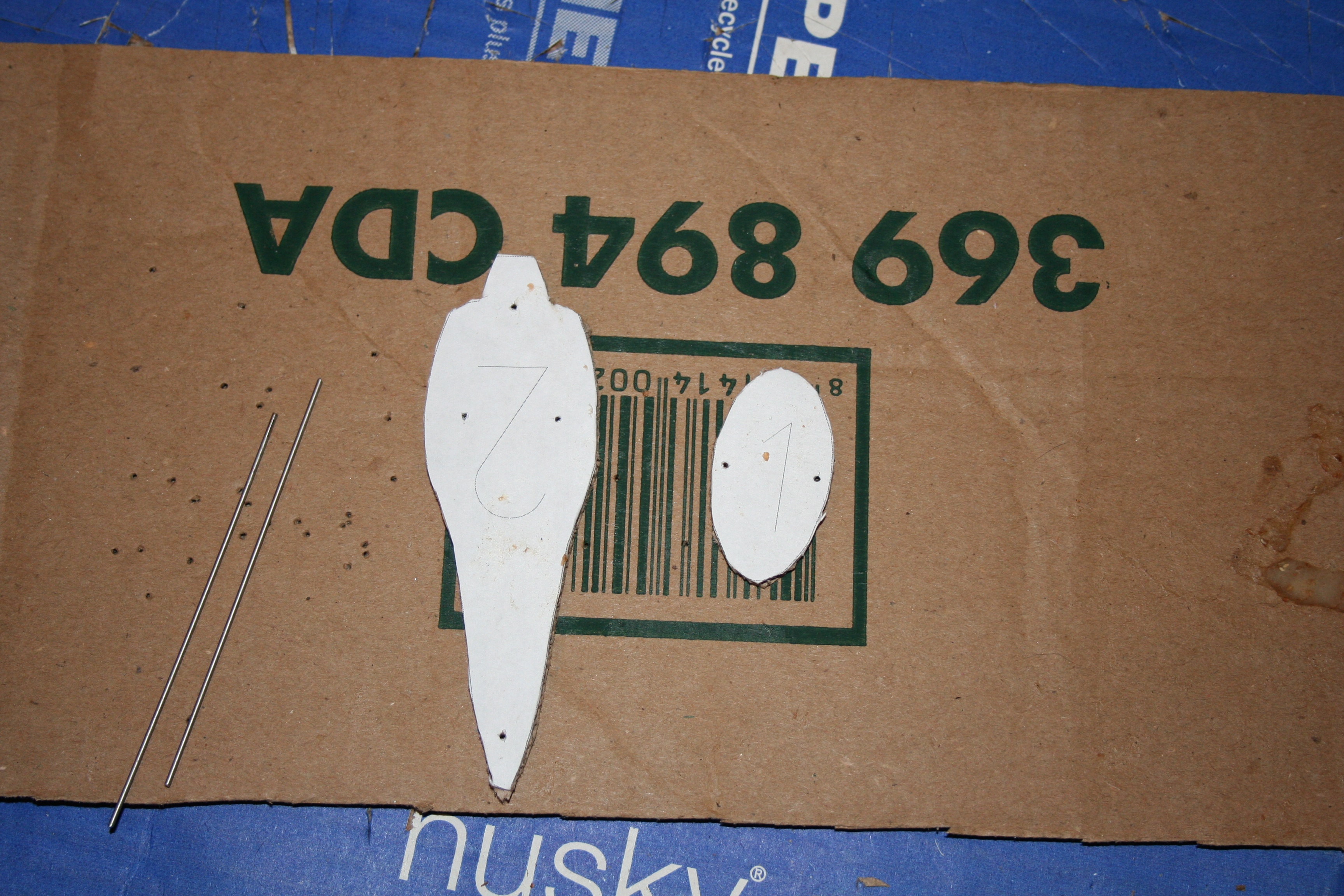
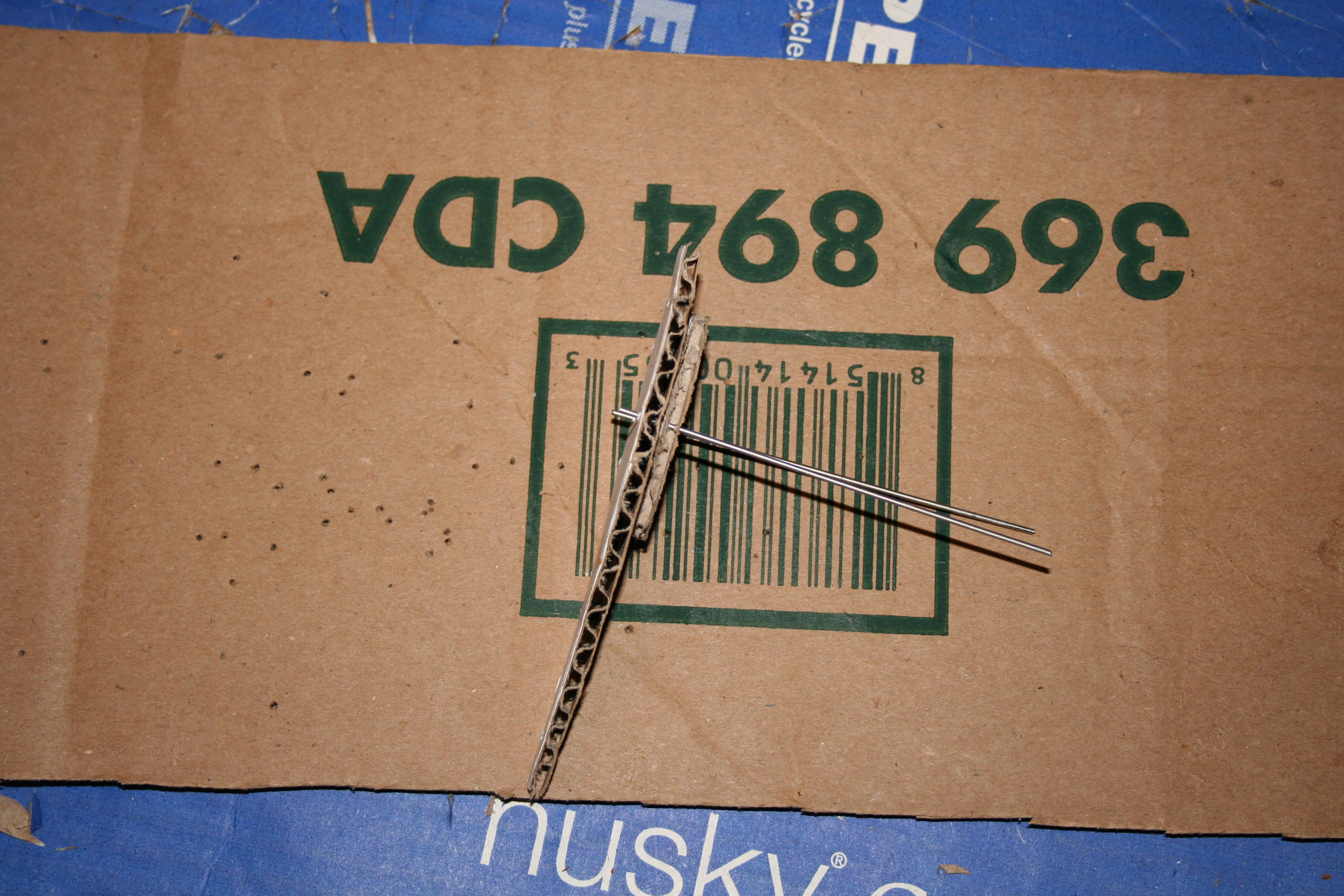
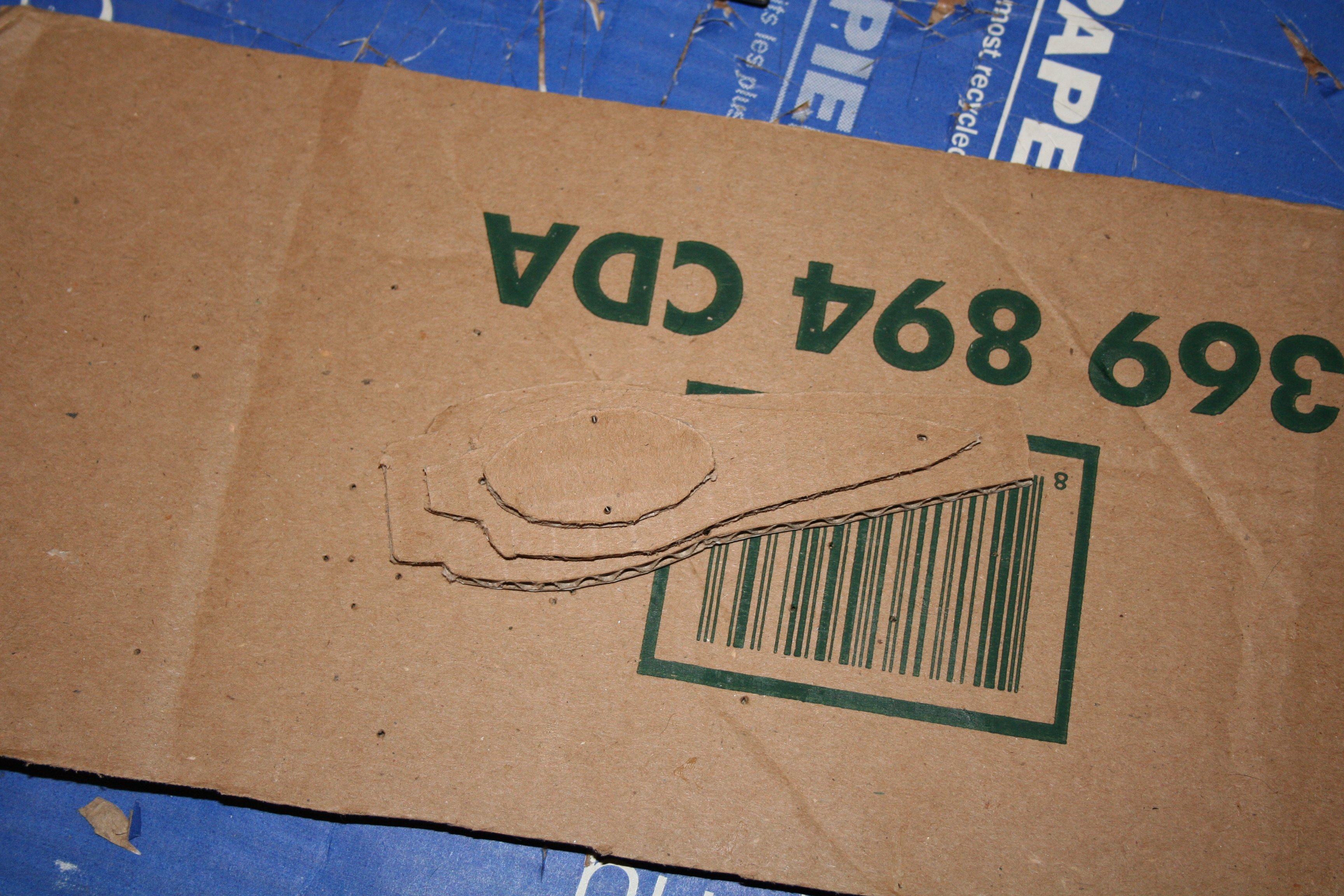
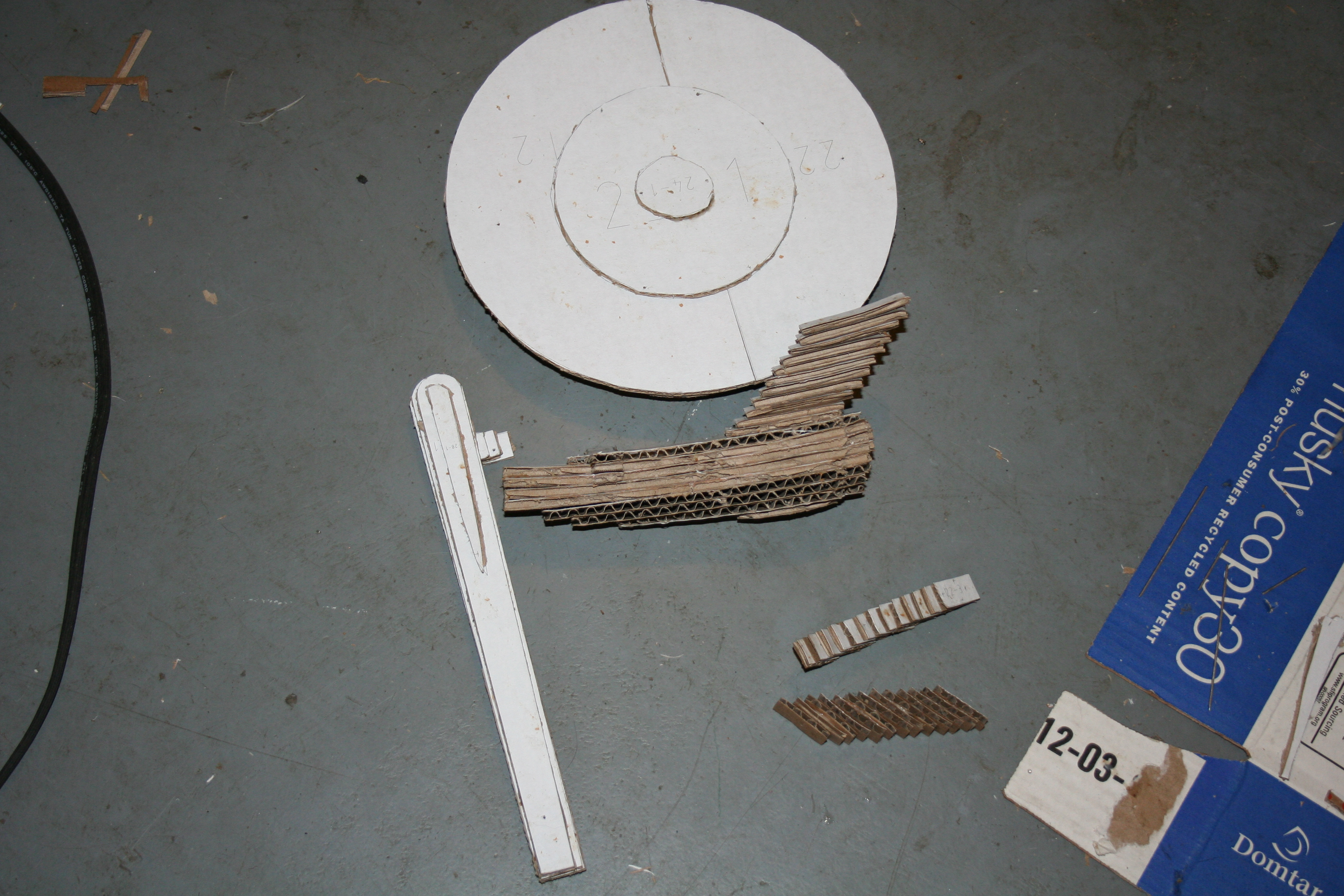
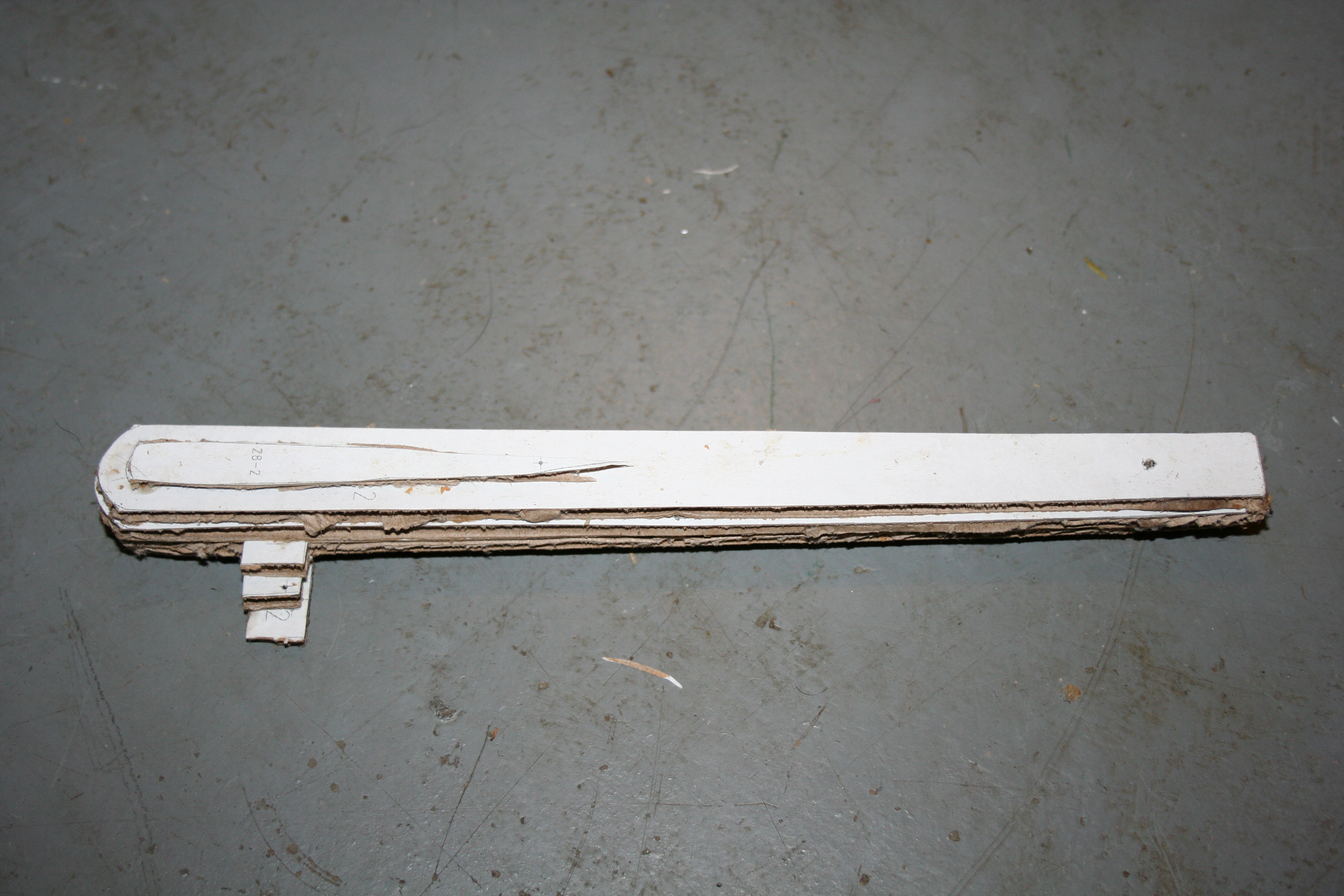
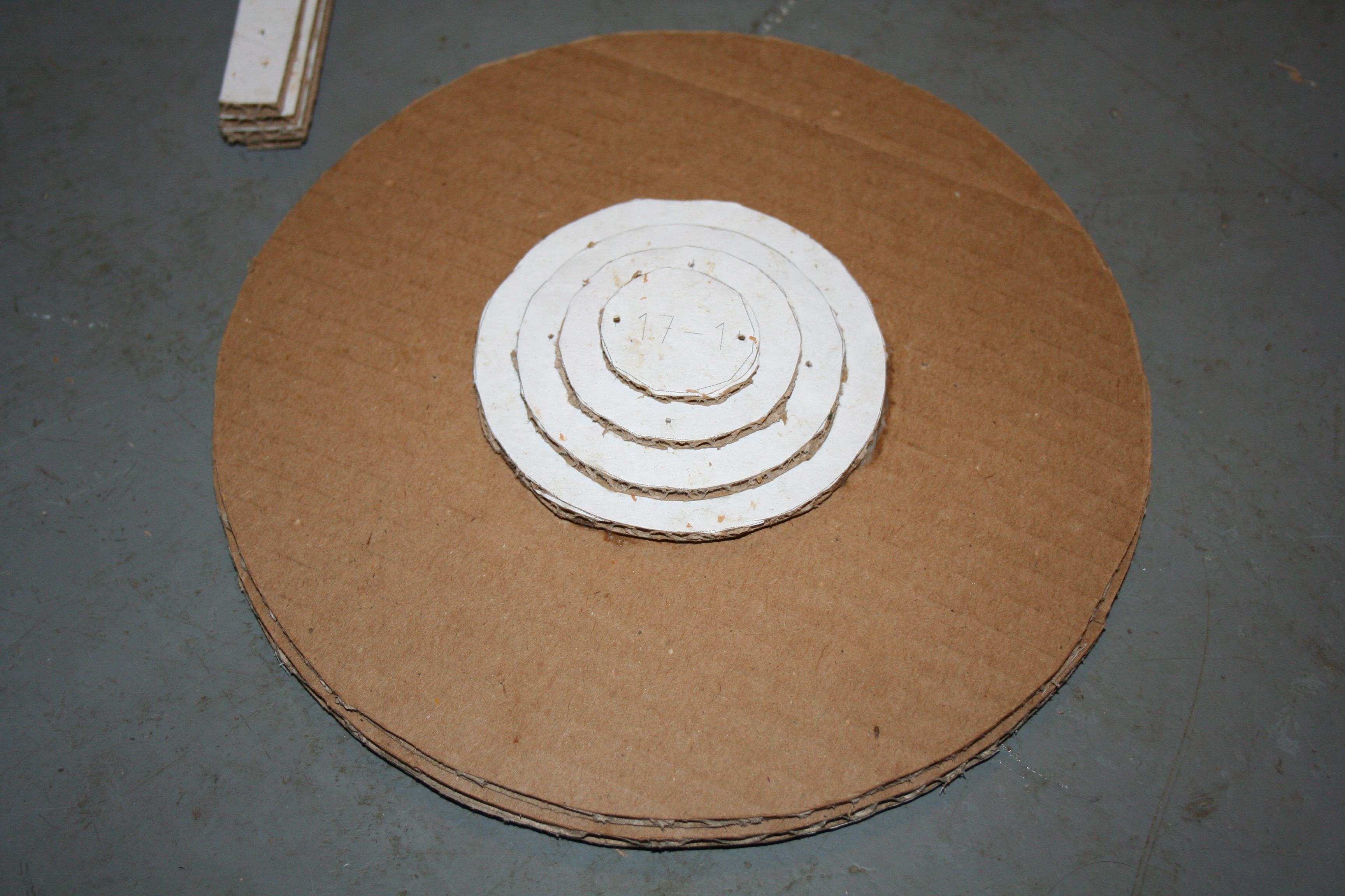
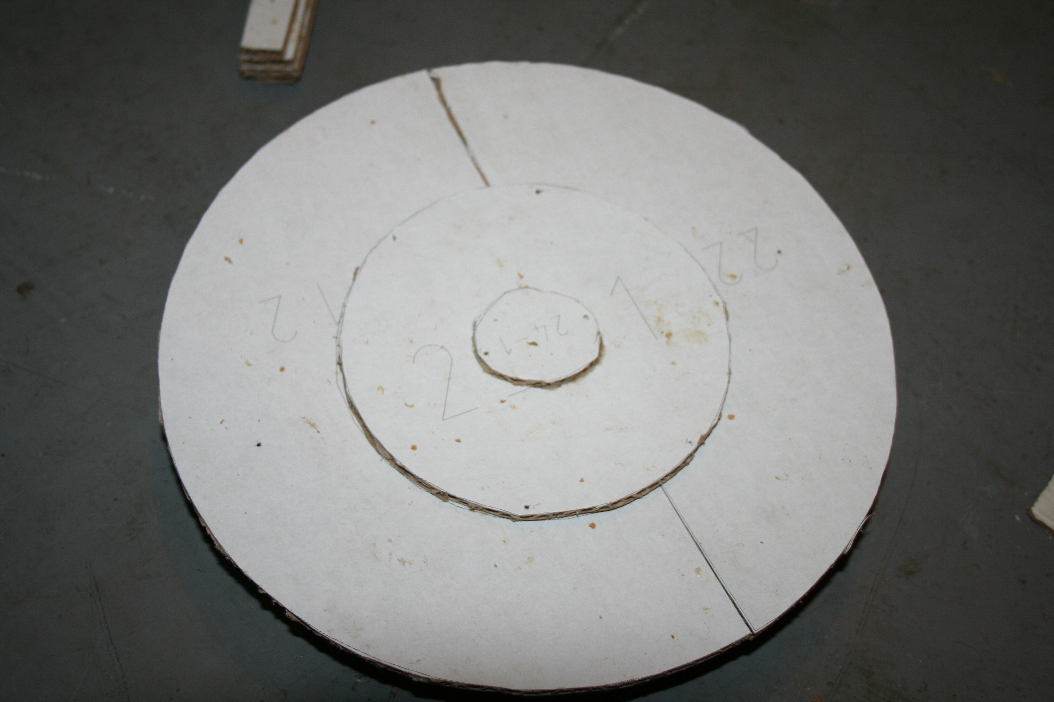
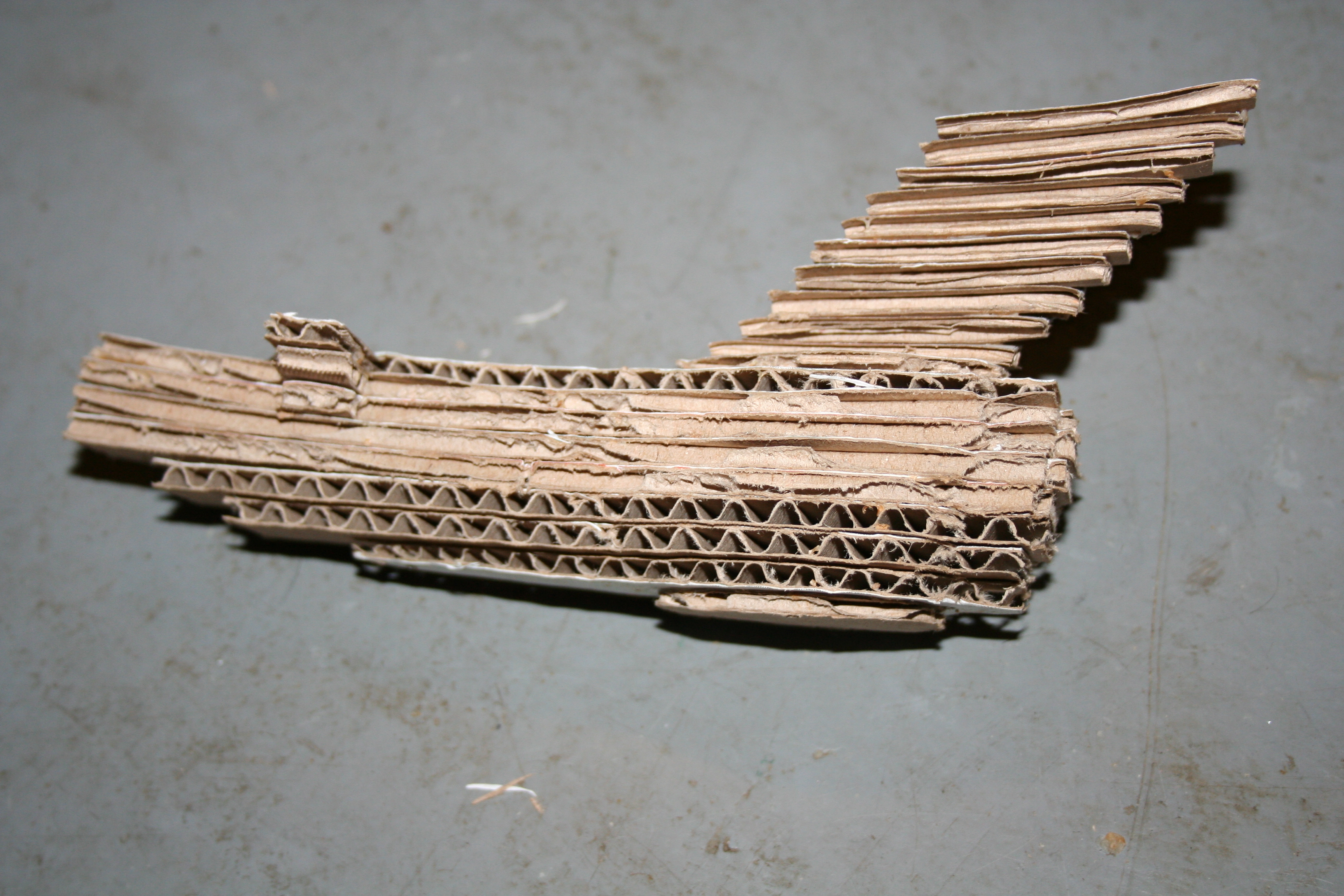
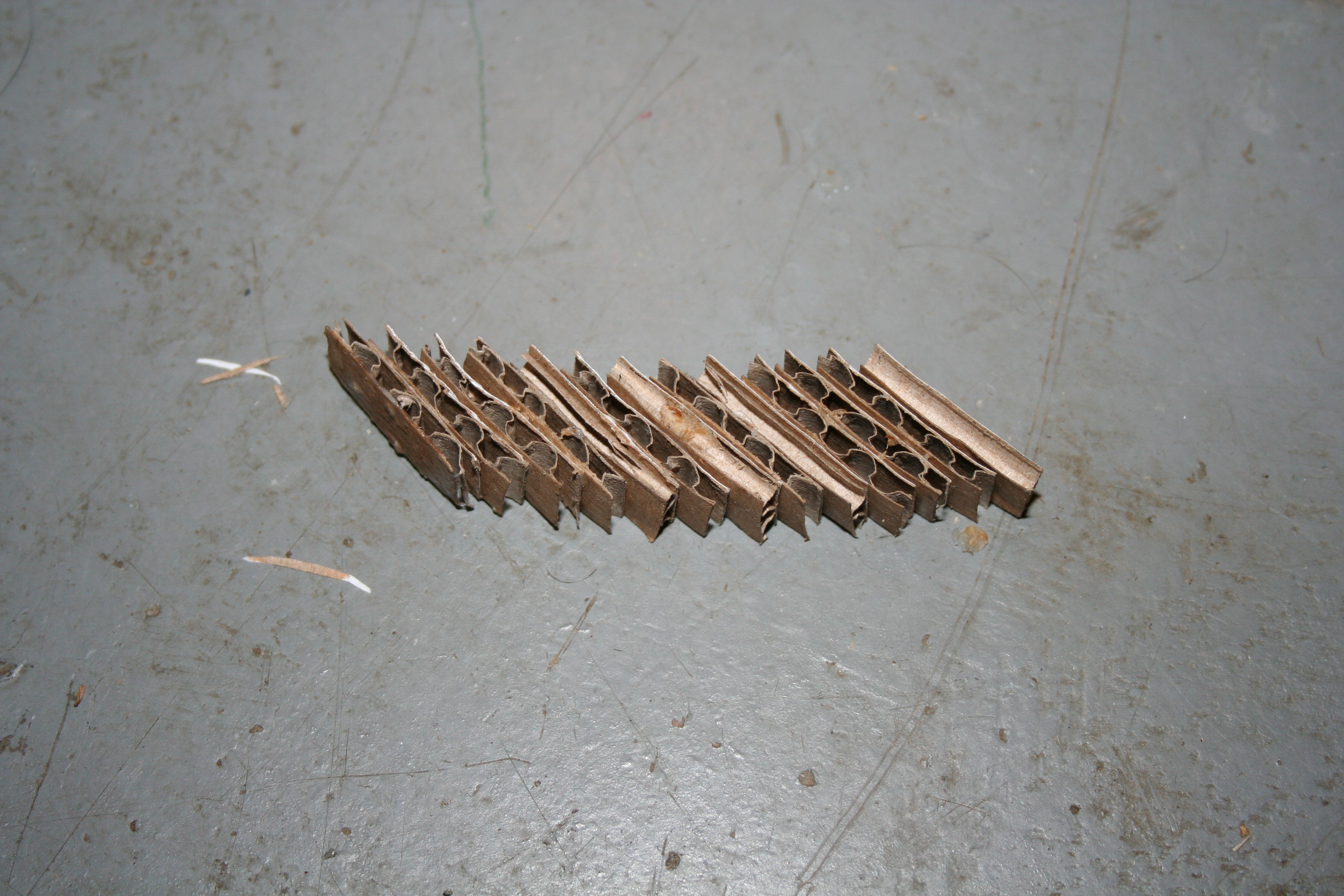
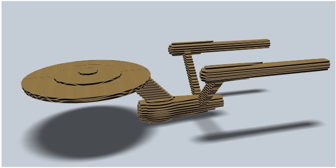
To make the main hull, align each cardboard piece in order from #1-10. Insert a pair of pins through the dots, then line them up with the corresponding markings on the next slice. Once you have them aligned, glue. To make the side struts, align each rectangular cardboard piece in order from #11-3 to 22-3 for the first strut. For the second matching strut align the remaining set of matching pieces. Insert a pair of pins through the dots, then line them up with the corresponding markings on the next slice. Glue the layers when you have them aligned. To make the front strut, assemble the long rectangular pieces in the same way as the side struts. Finally, glue the front strut to the main body.
Assemble the remaining pieces following the assembly in Make.
Assemble the remaining pieces following the assembly in Make.
Assemble
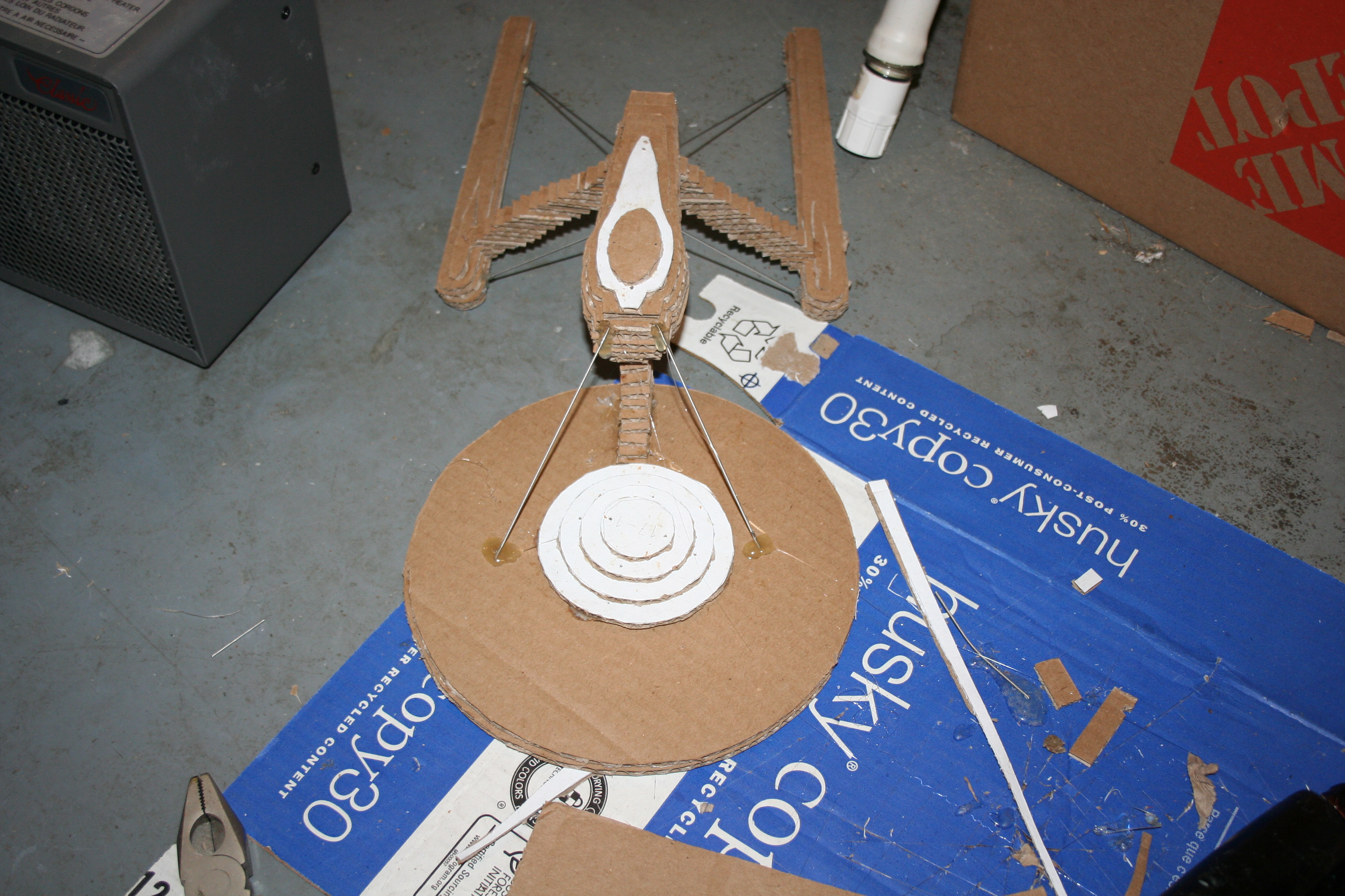
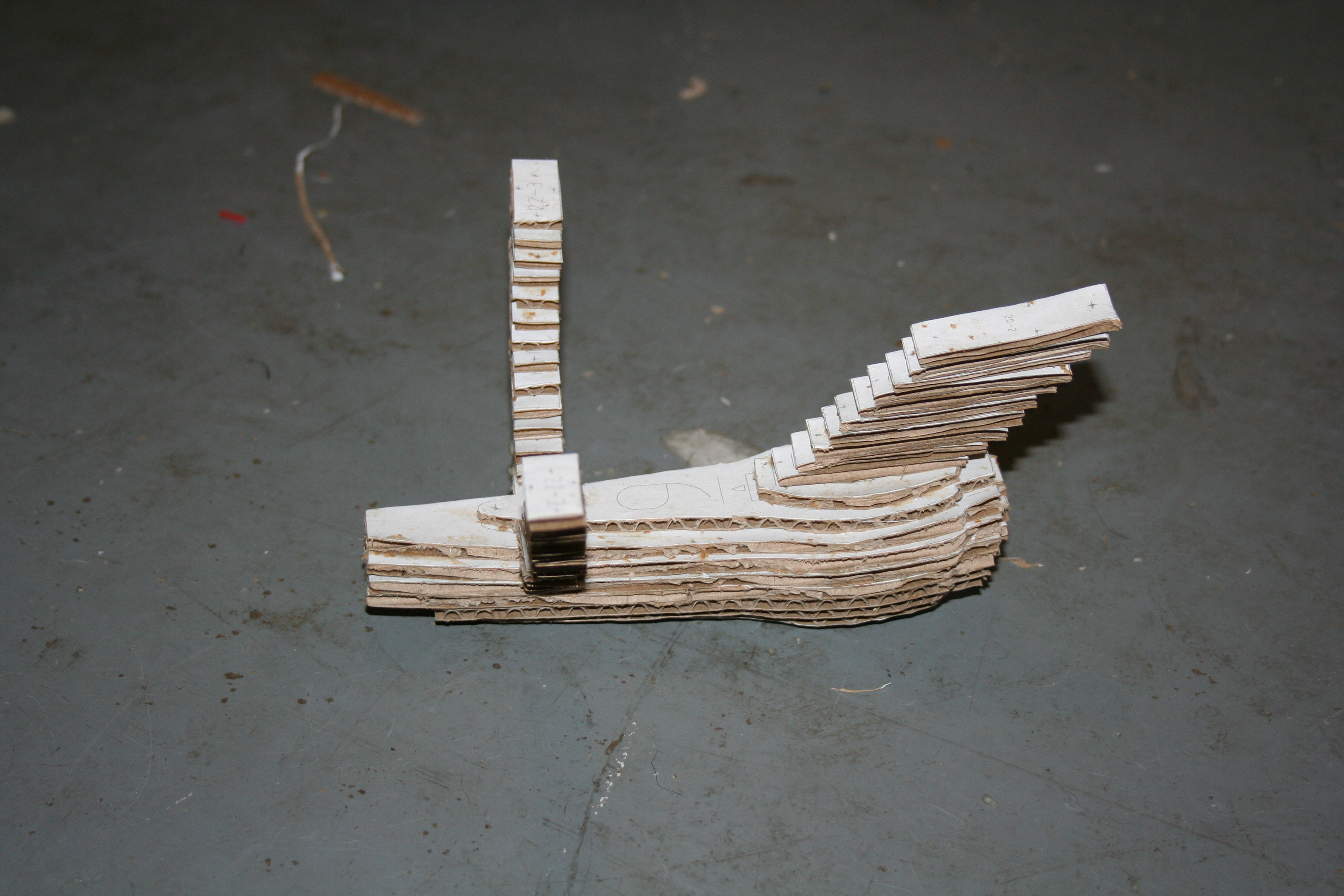
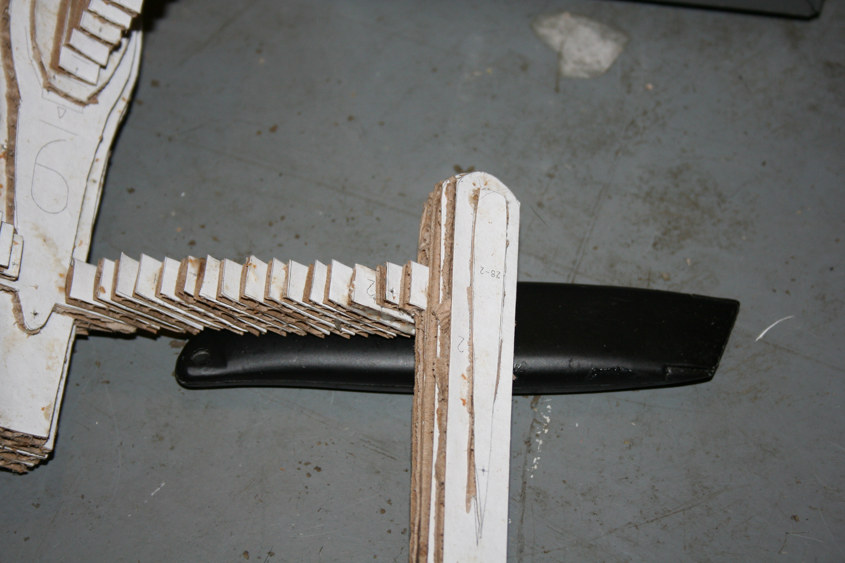
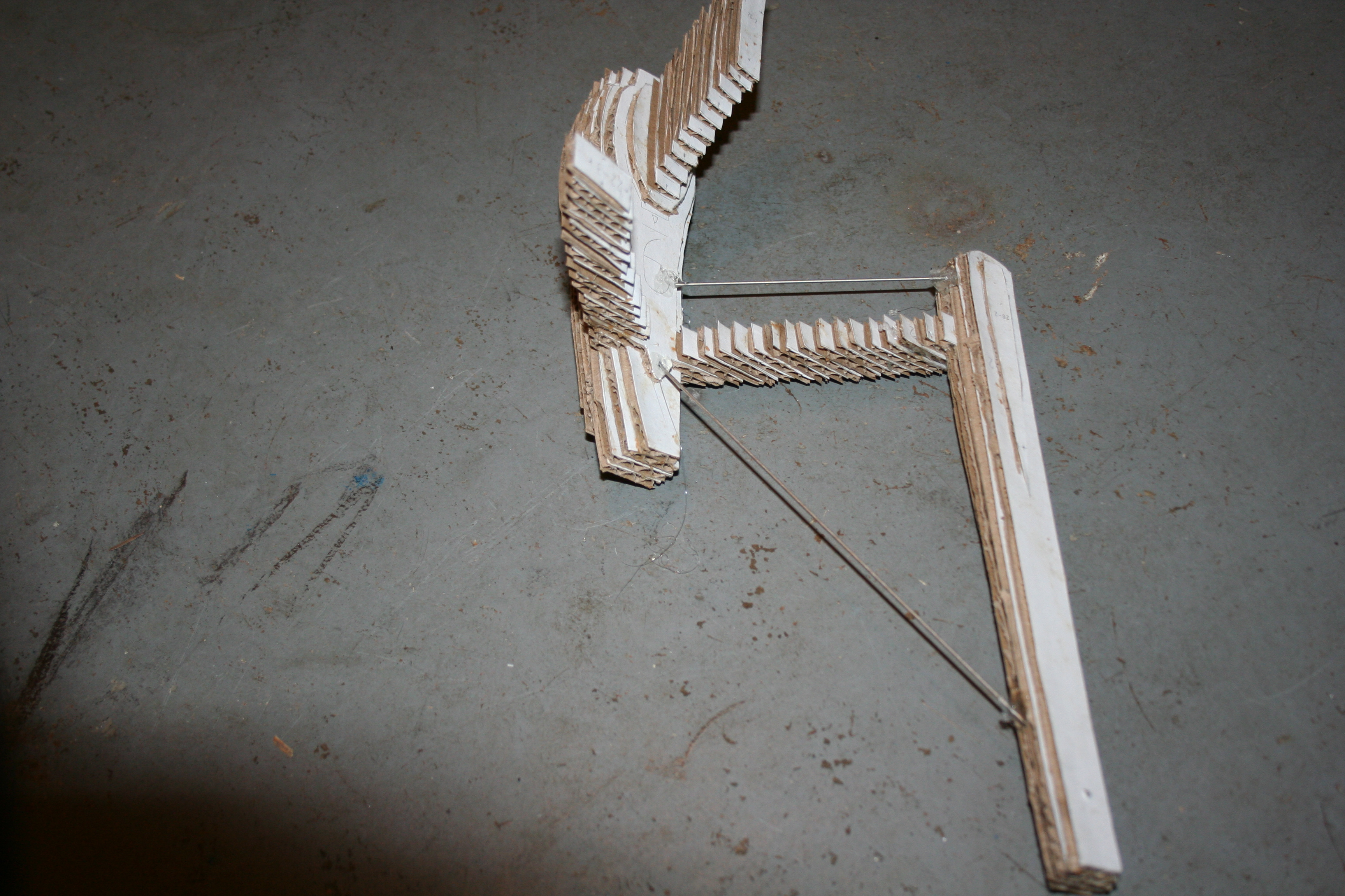
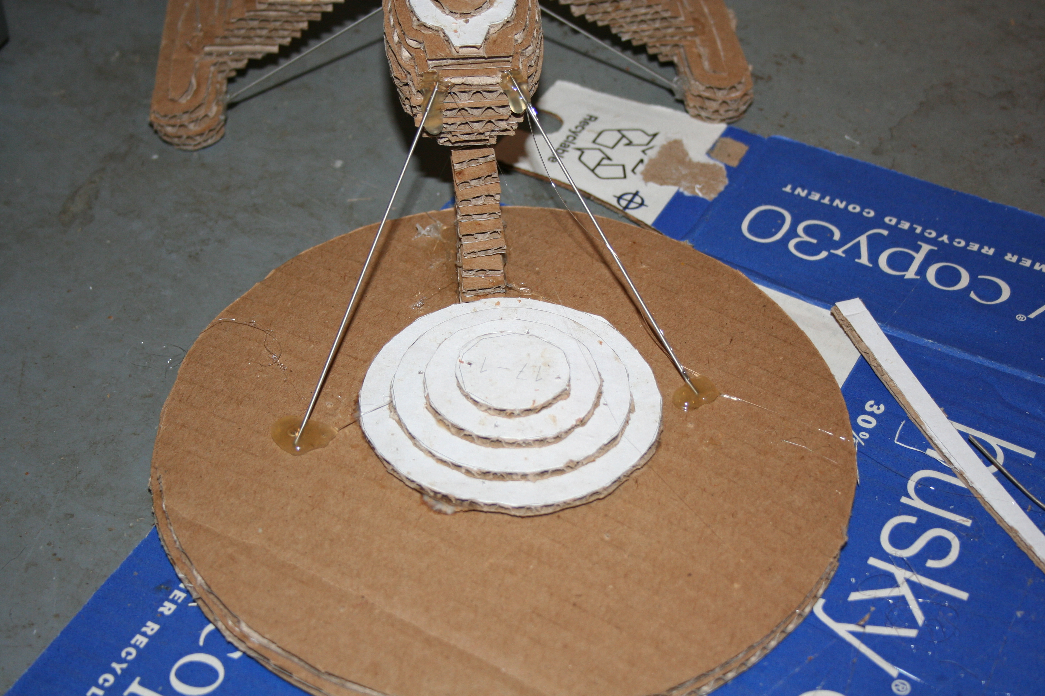
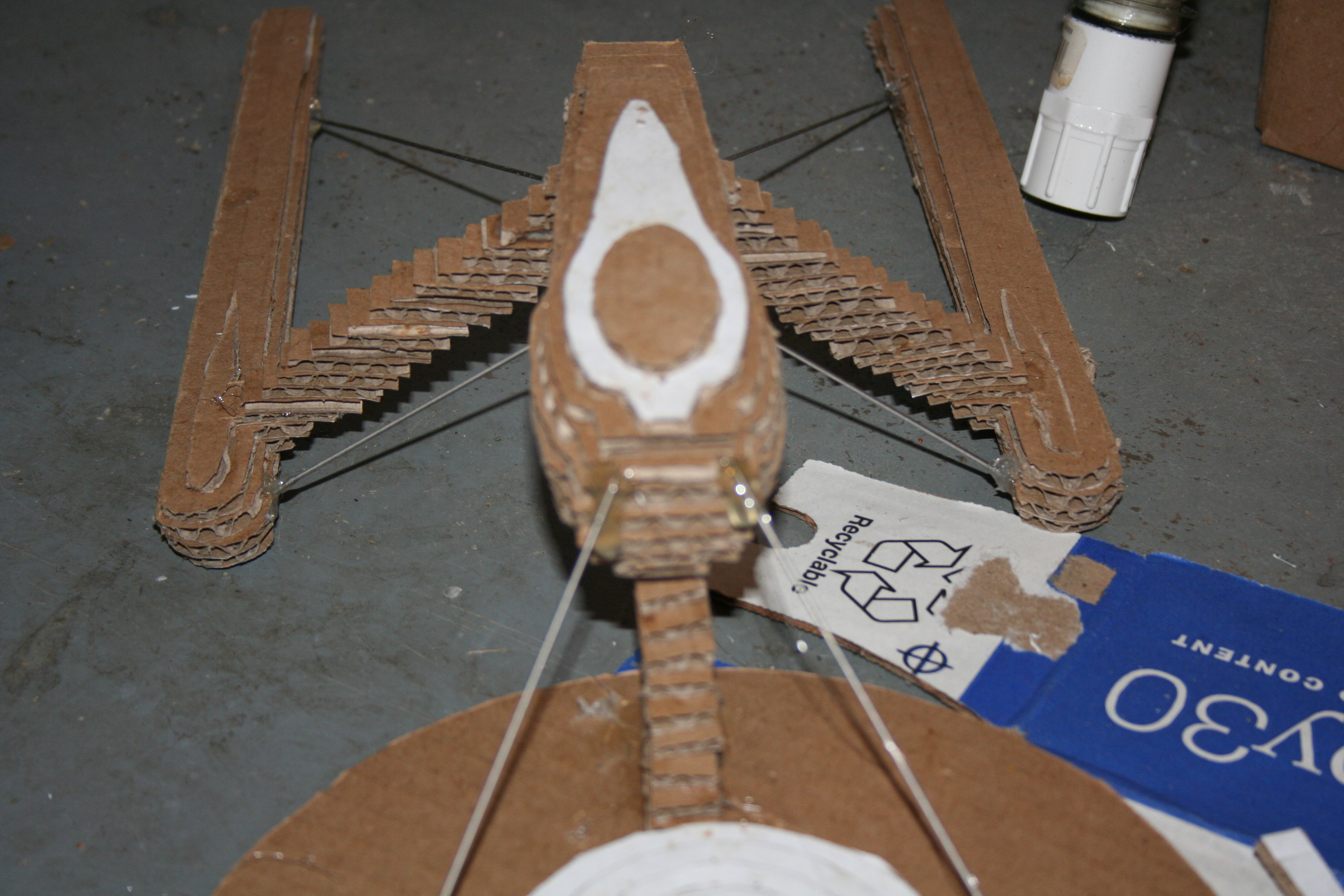
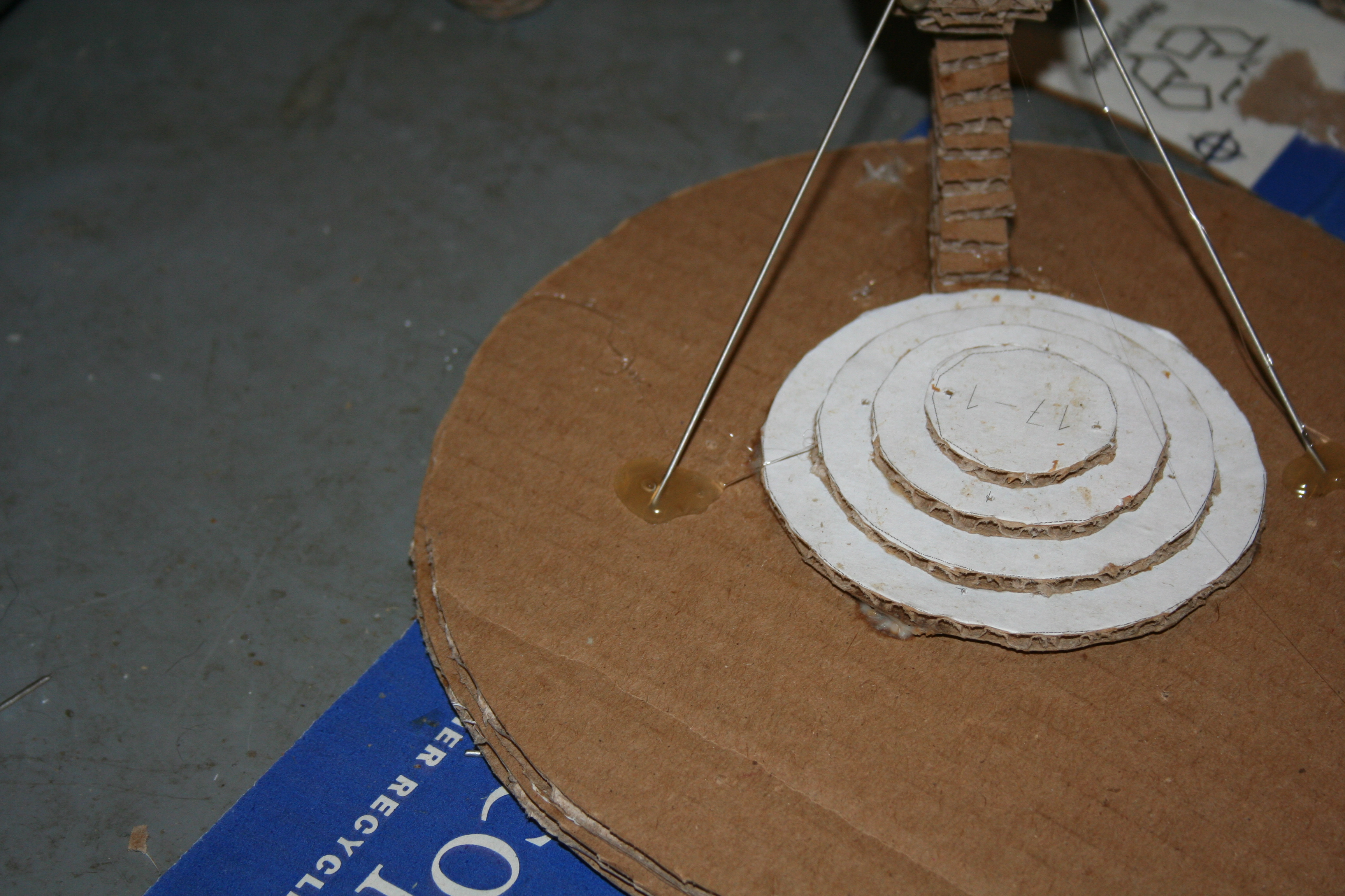
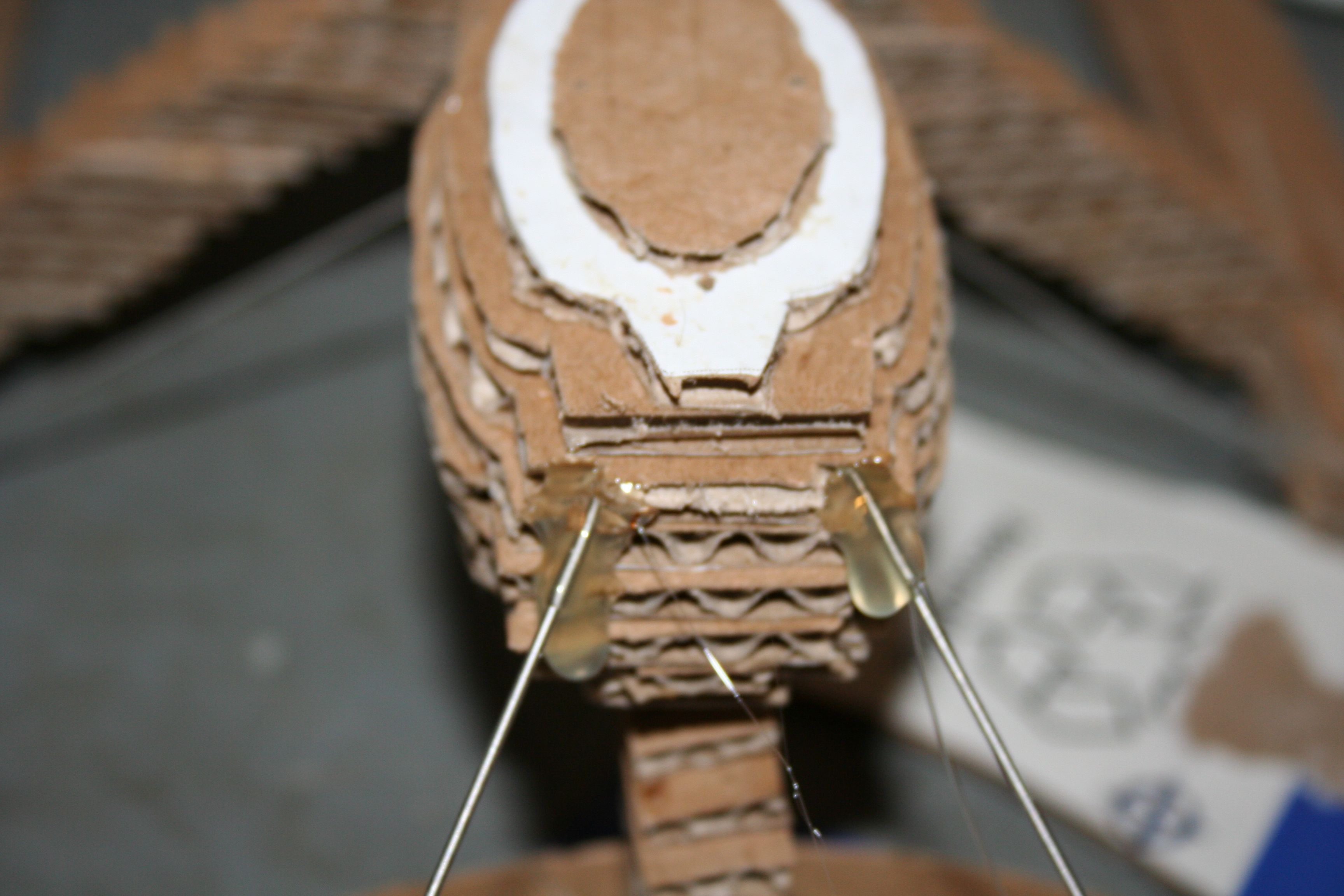
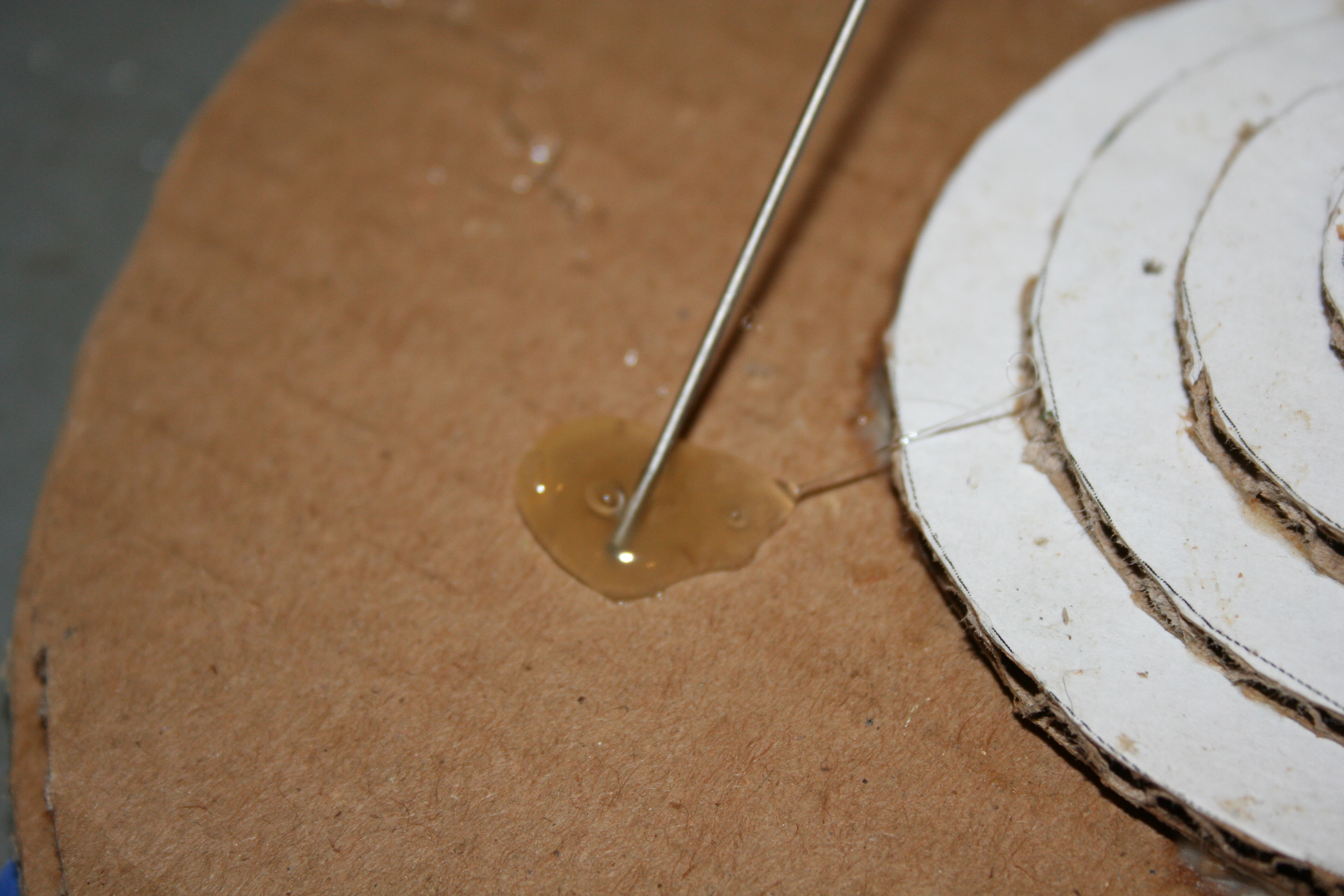
Start by hot gluing the two side struts to the main body. Then, hot glue the engines to the ends of the struts. Next, cut off two nine and twelve cm pieces of straitened wire. Then glue the nine cm piece from the front of the engine the the main hull and glue the sixteen cm piece from the end of the engines to the main body, repeat for both sides. Now hot glue the the upper hull to the front strut so that the strut touches the first cardboard circle(see fifth photo). Finally, cut two ten cm lengths of straightened wire and hot glue between the main body and the upper hull.
Wiring the LEDs
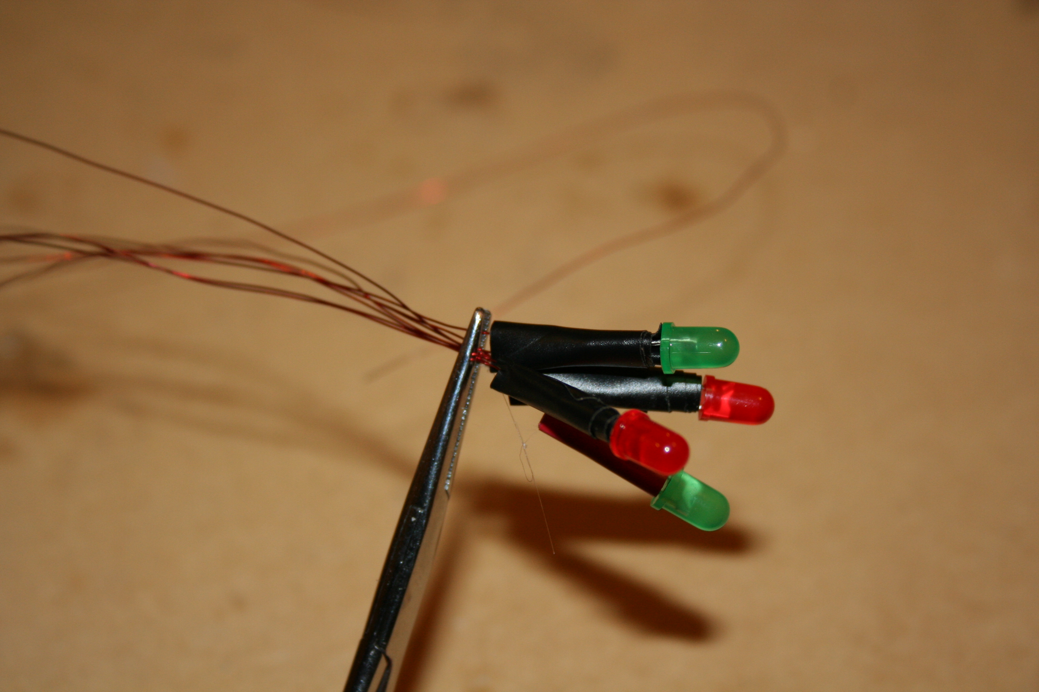
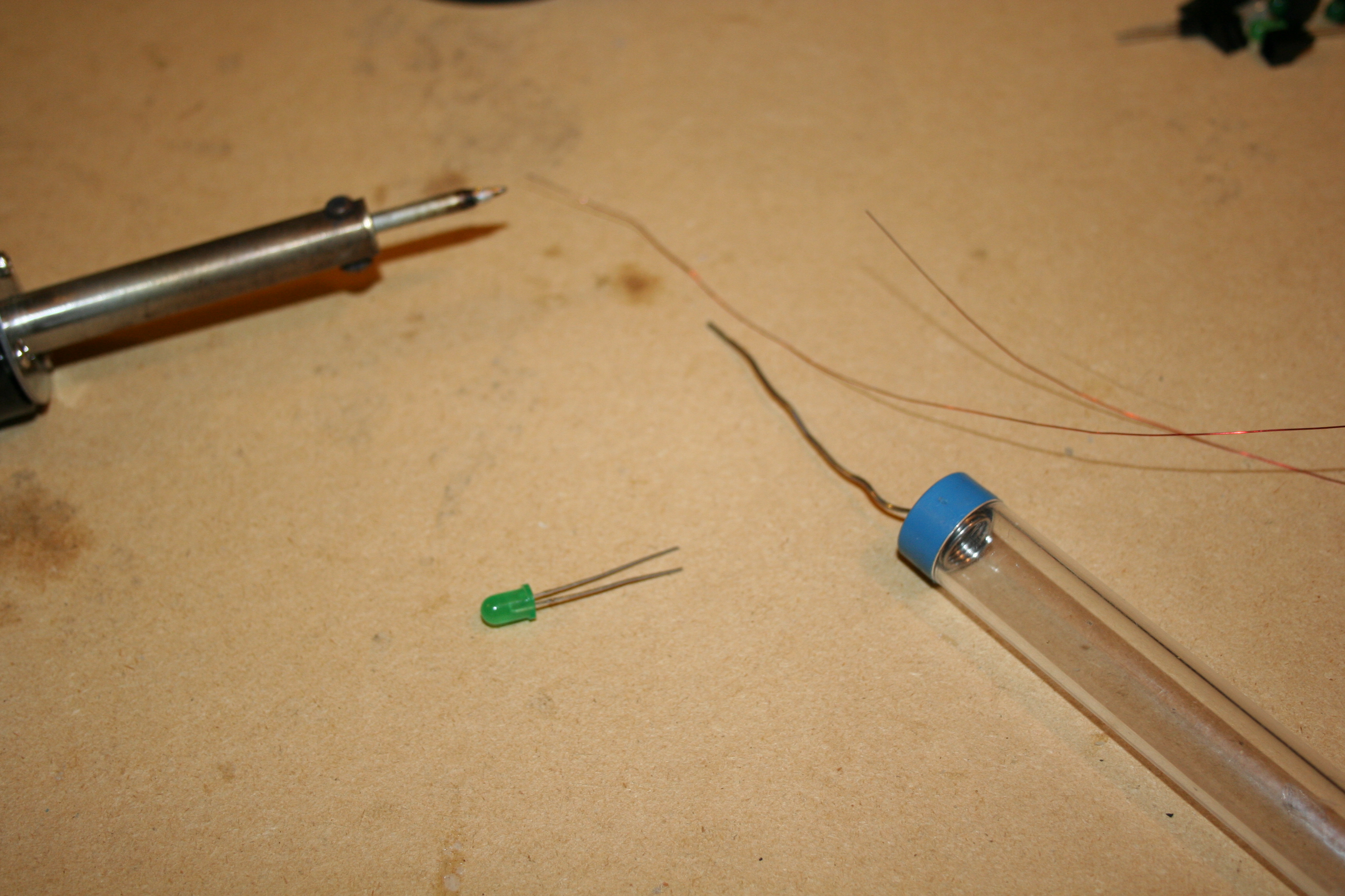
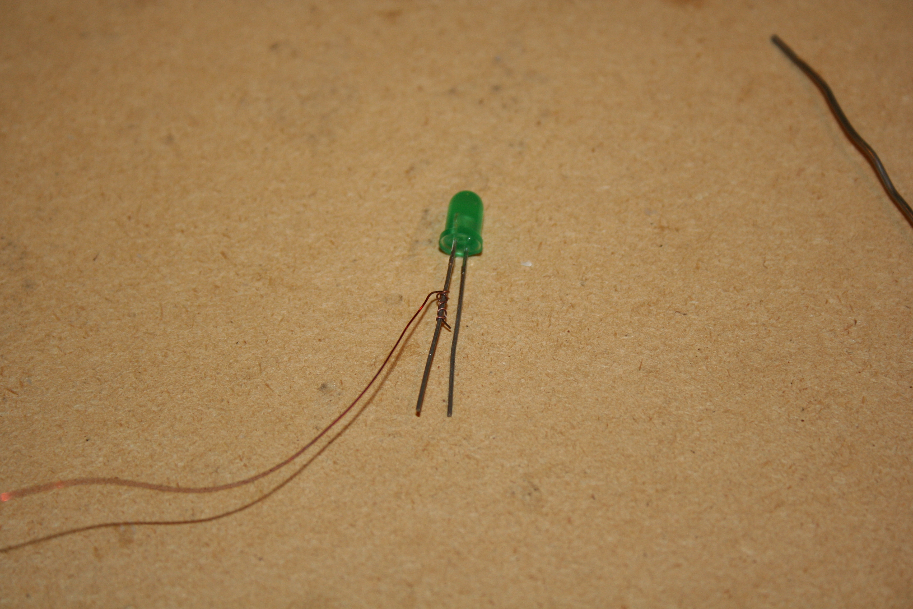
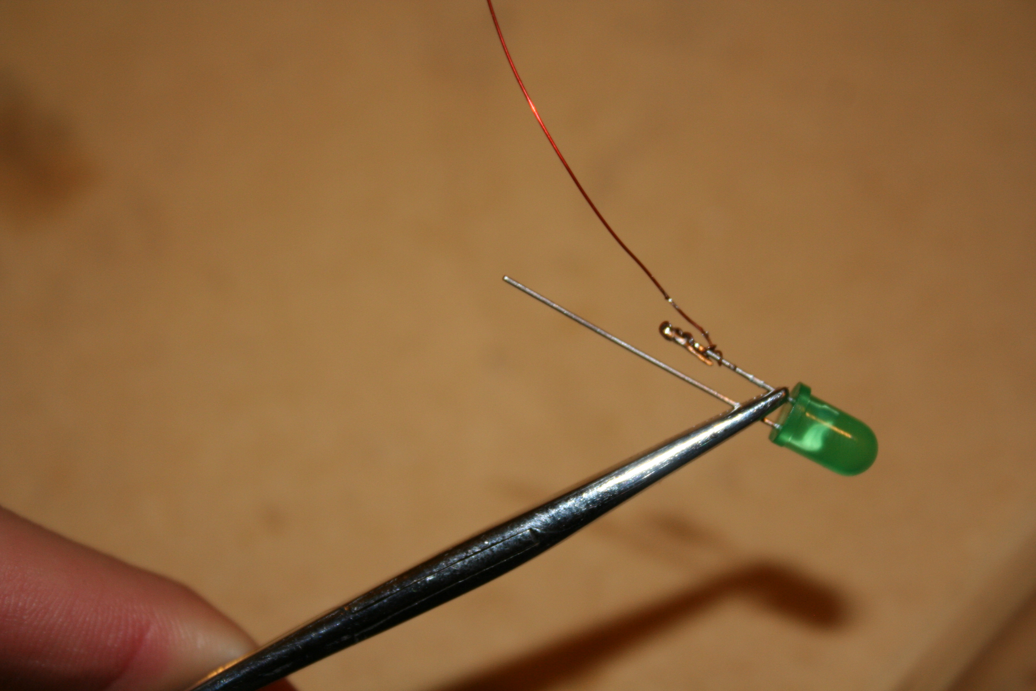
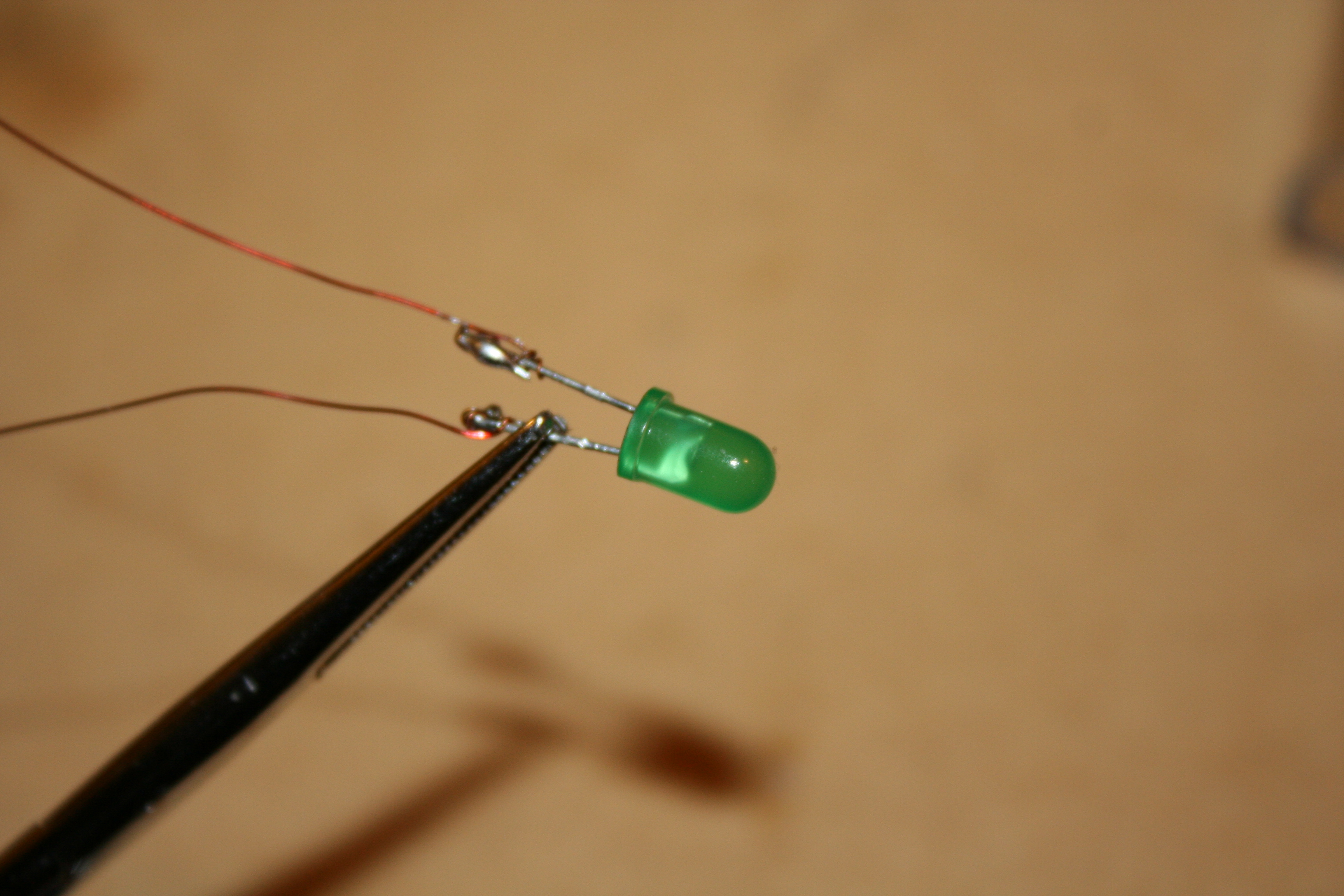
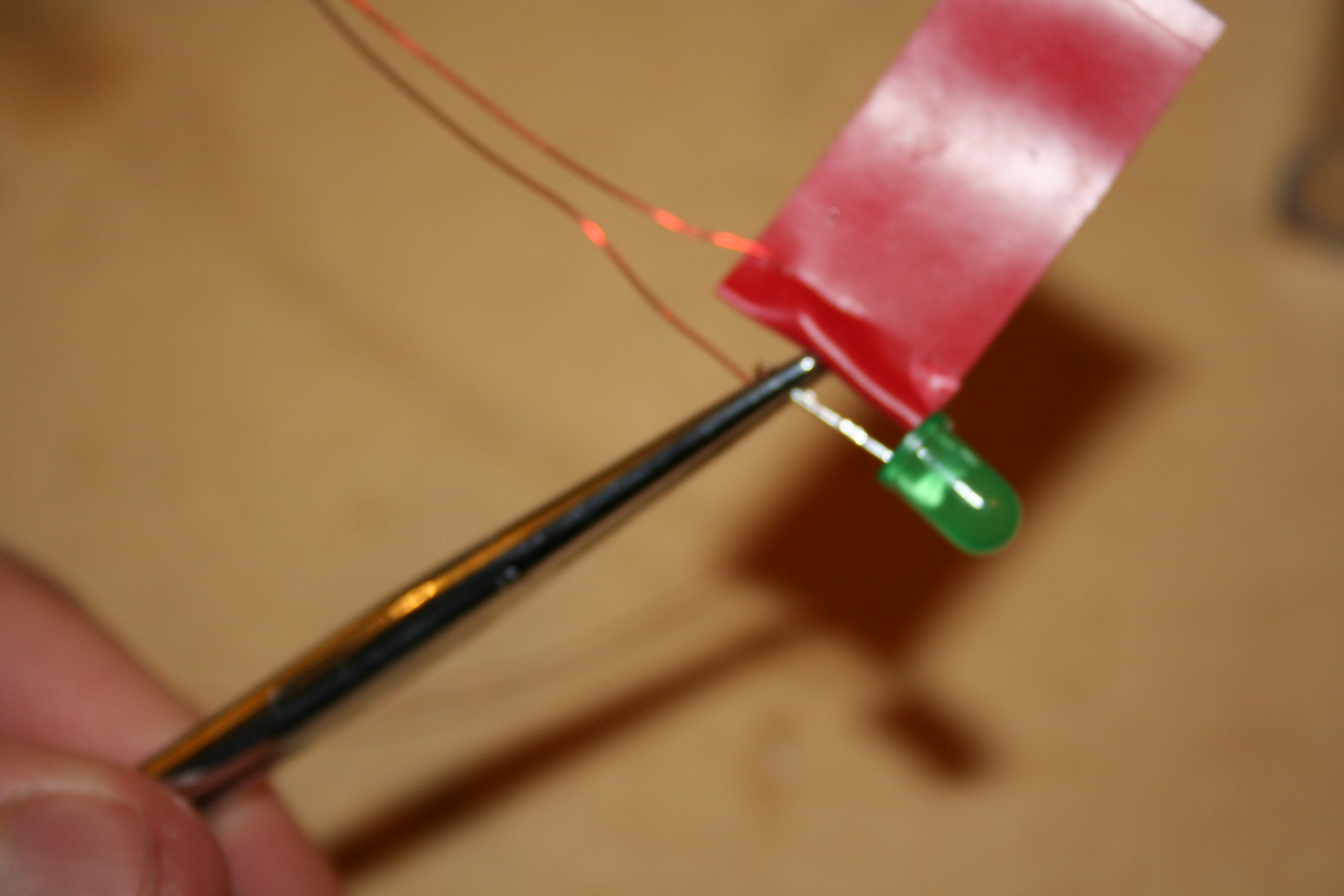
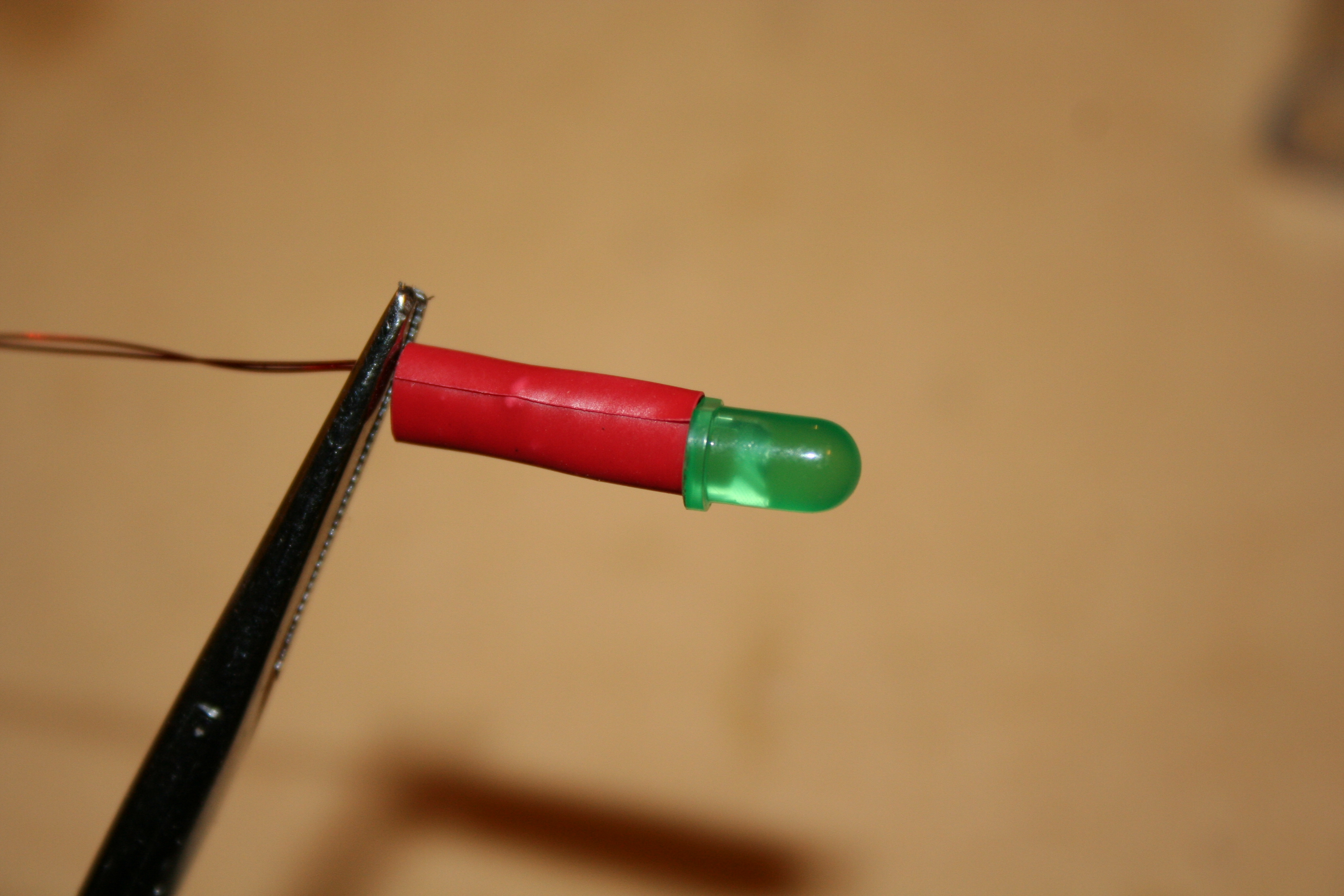
First, cut twenty 45 cm pieces of 30 awg enamel wire and strip two cm of enamel off each end. Next, wrap the end of one wire around the leg of a LED, then bend the leg in half and solder, repeat for the other leg. Finally, cut off a small piece of electrical tape and then fold part of it over a leg, then tightly wrap it around both legs, repeat for the other nine LEDs.
Final Assembly
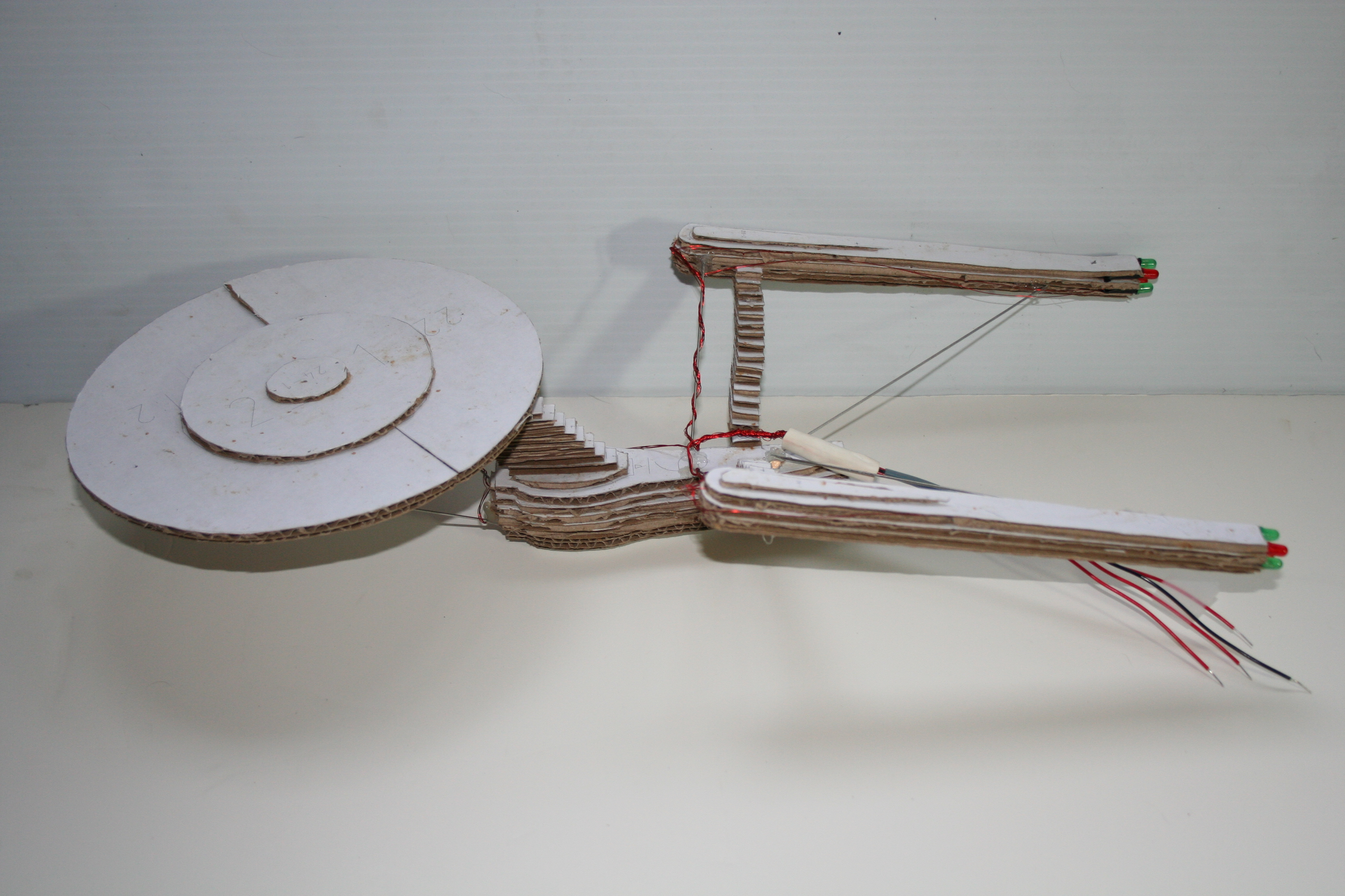
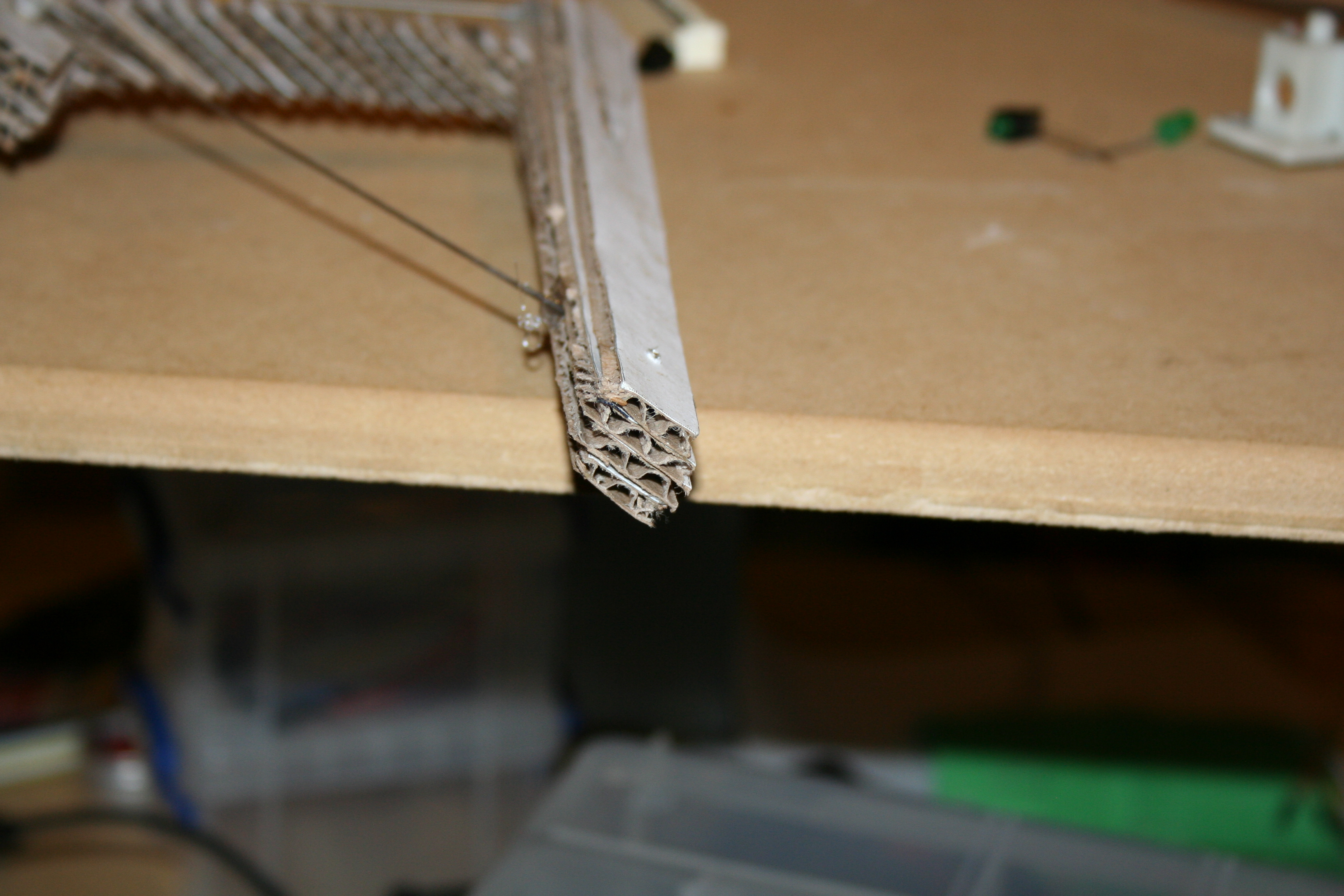
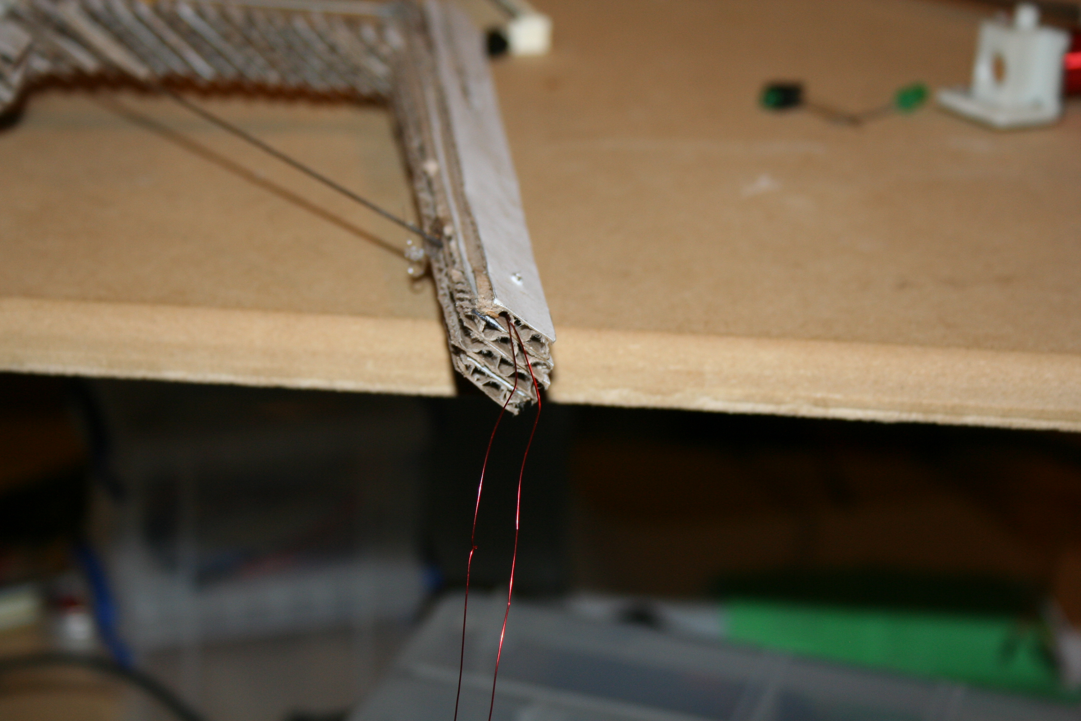
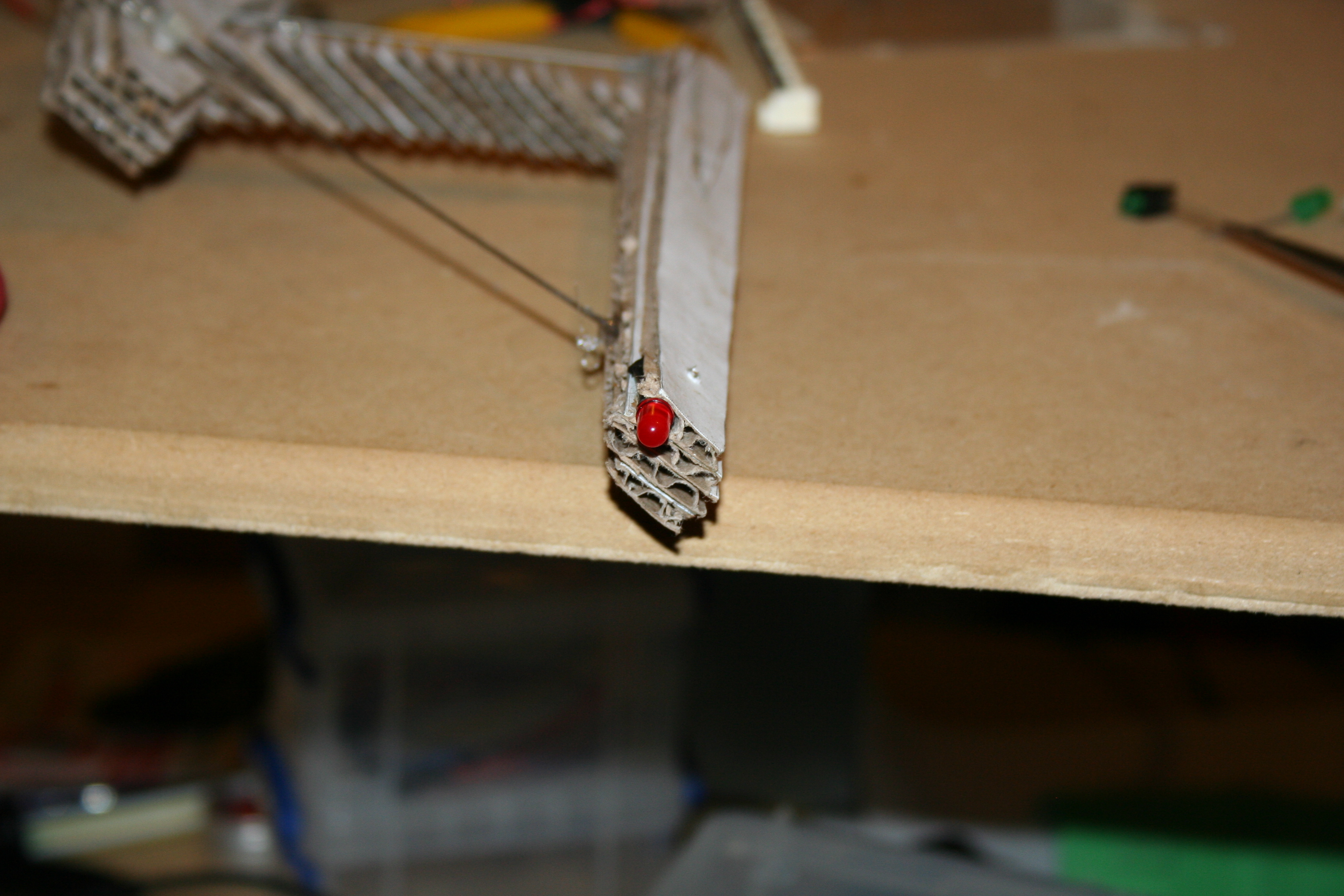
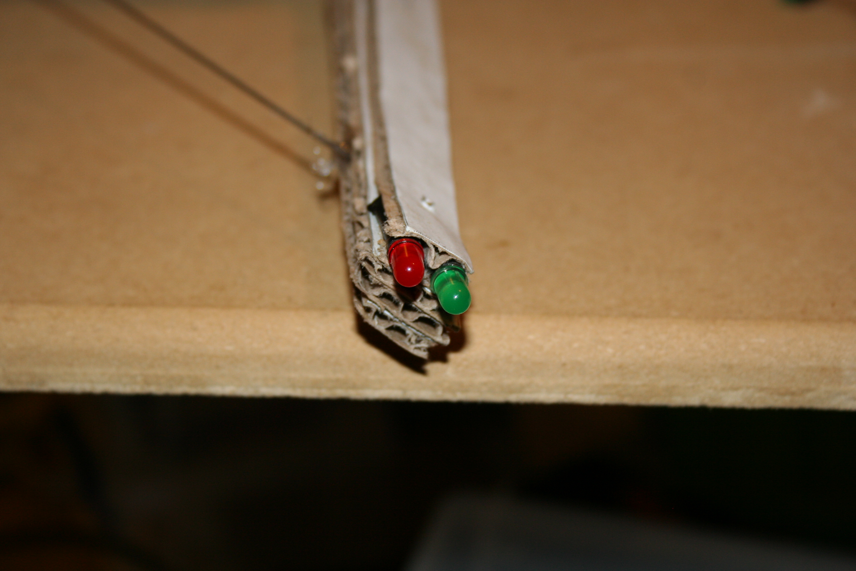
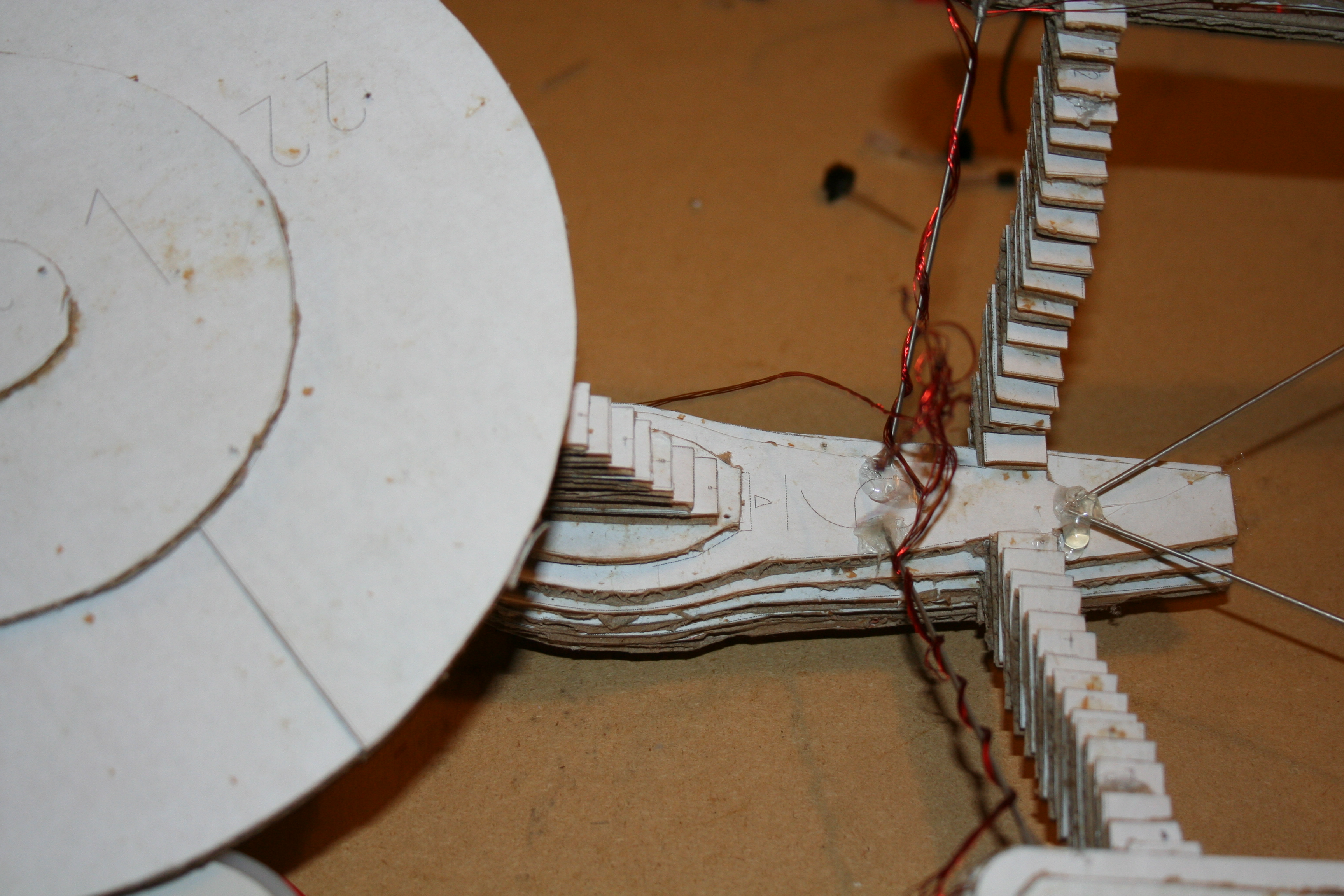
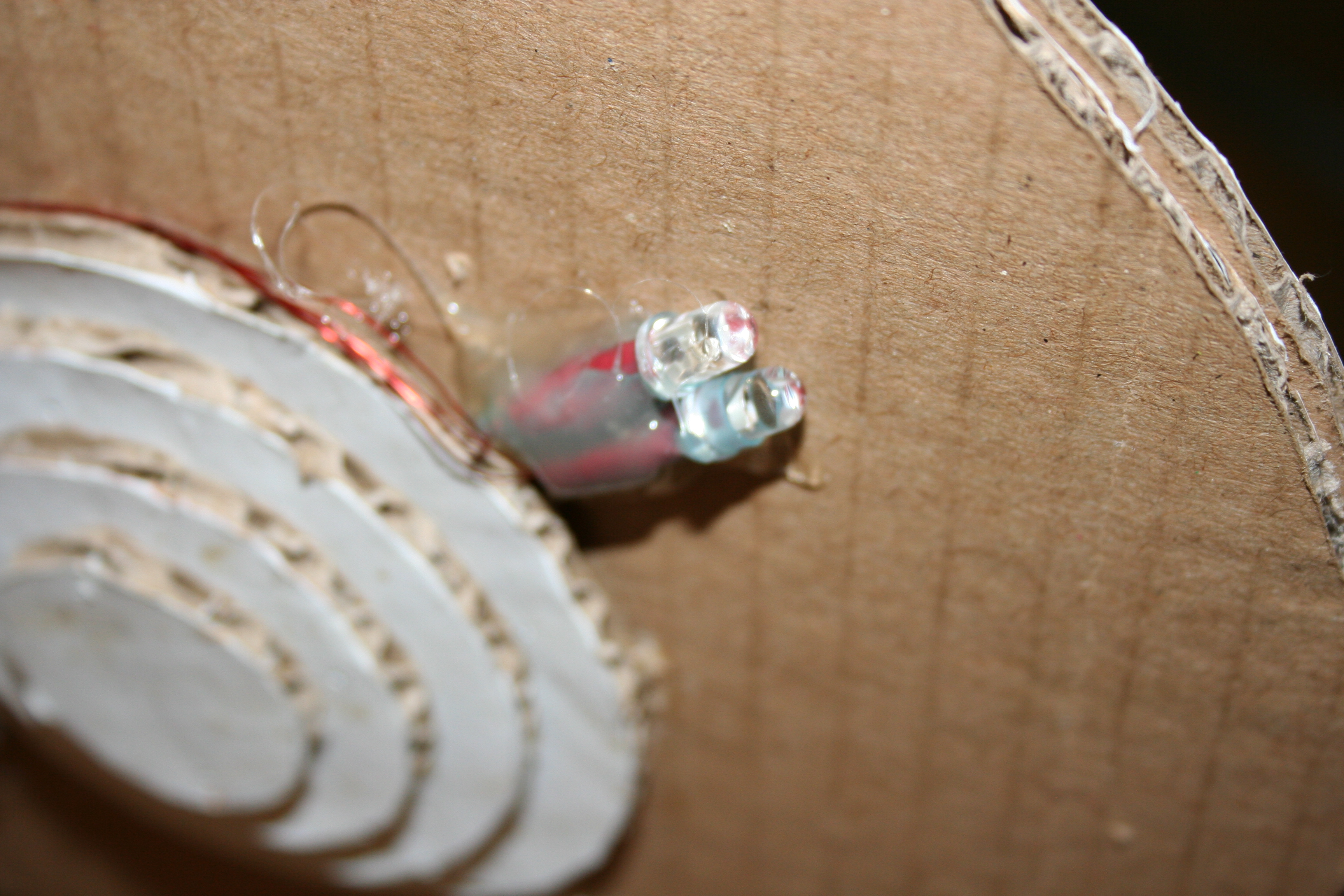
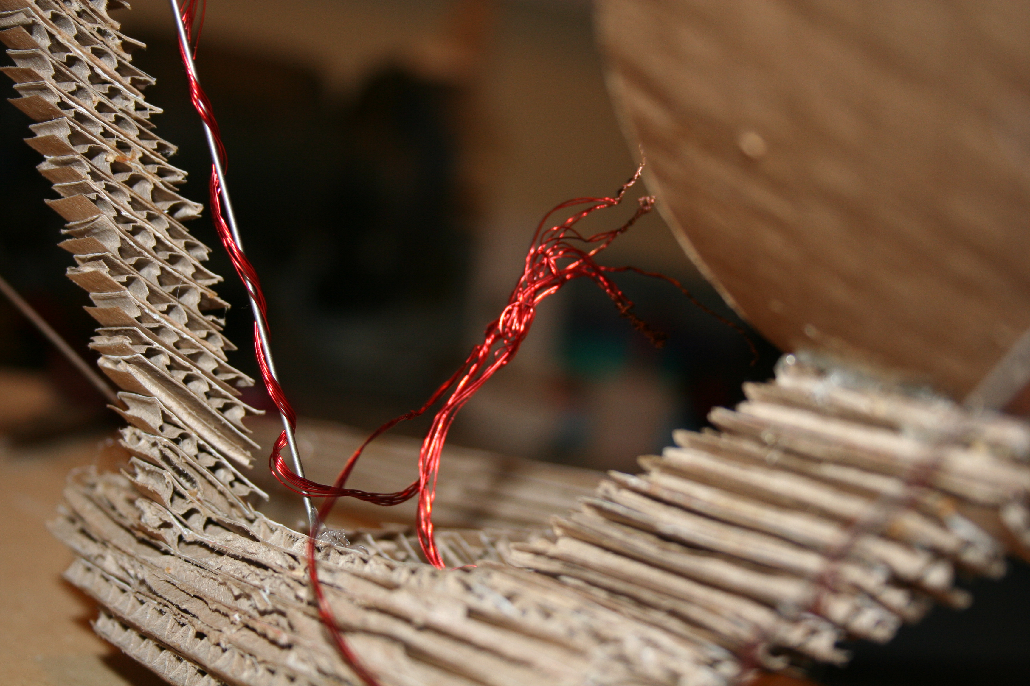
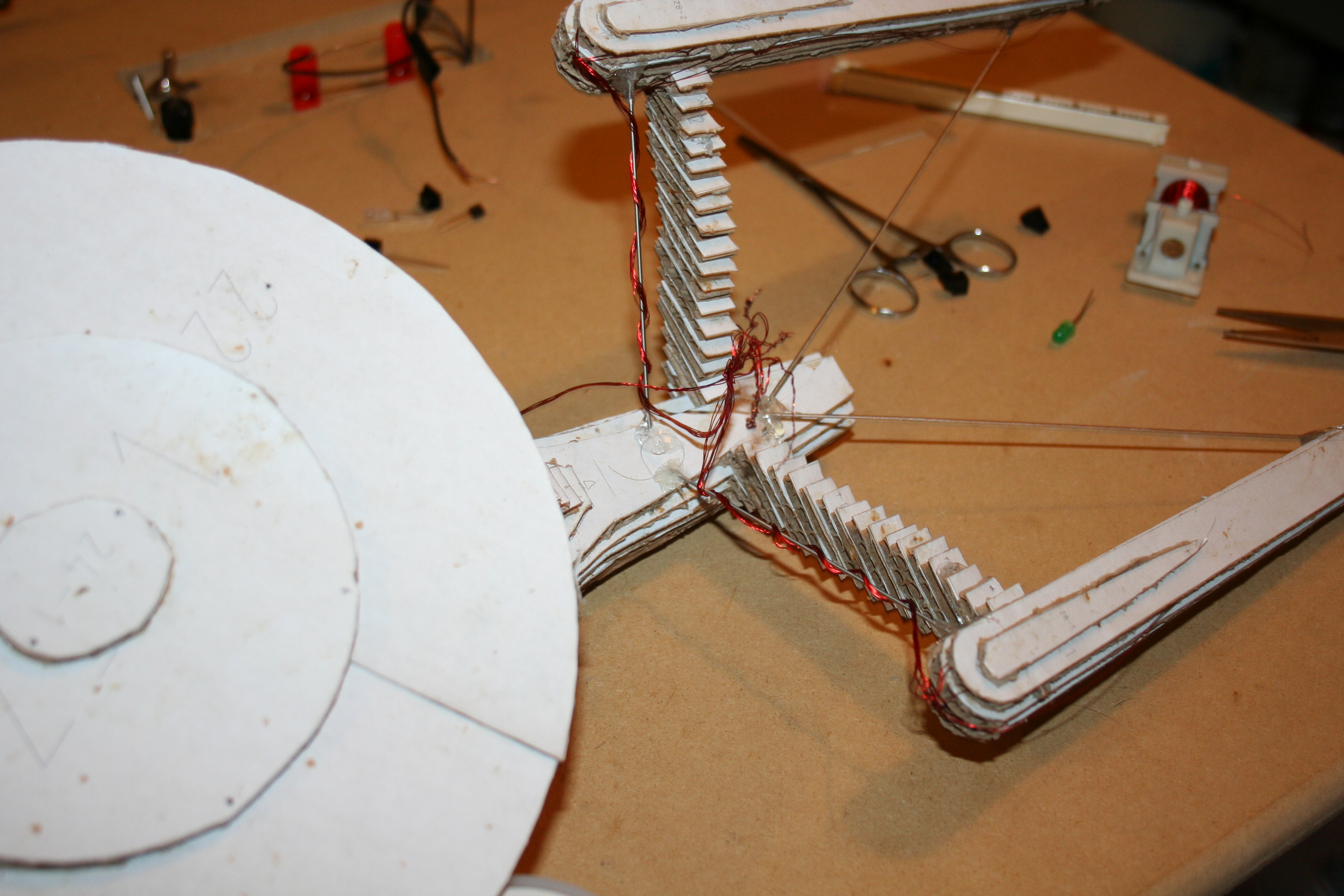
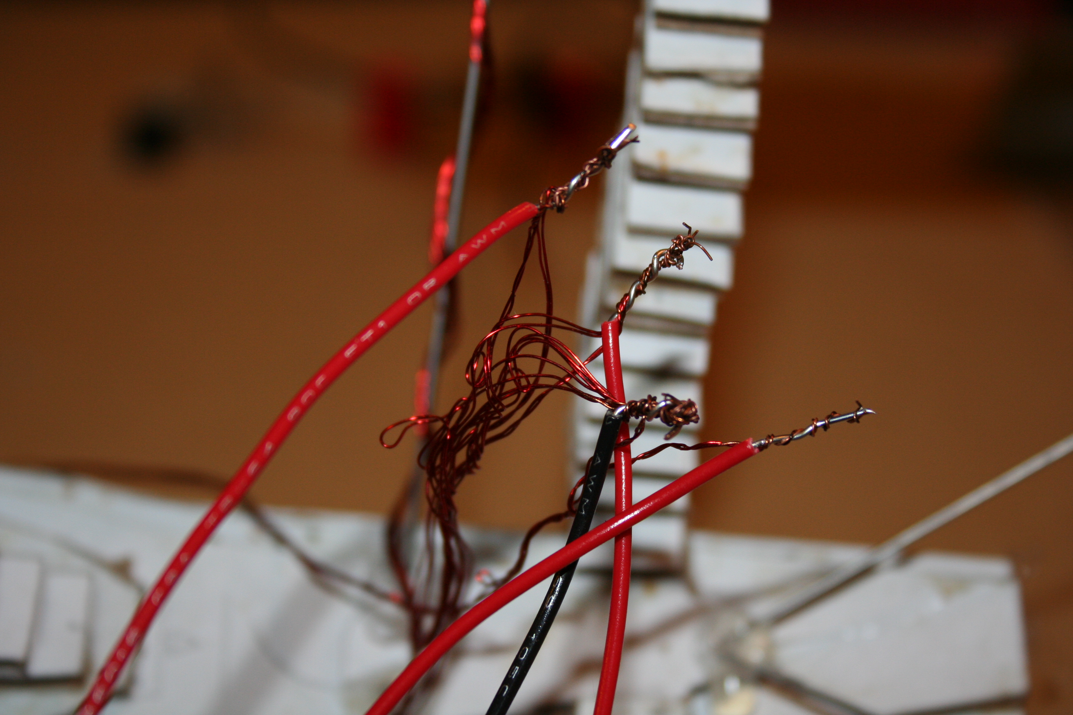
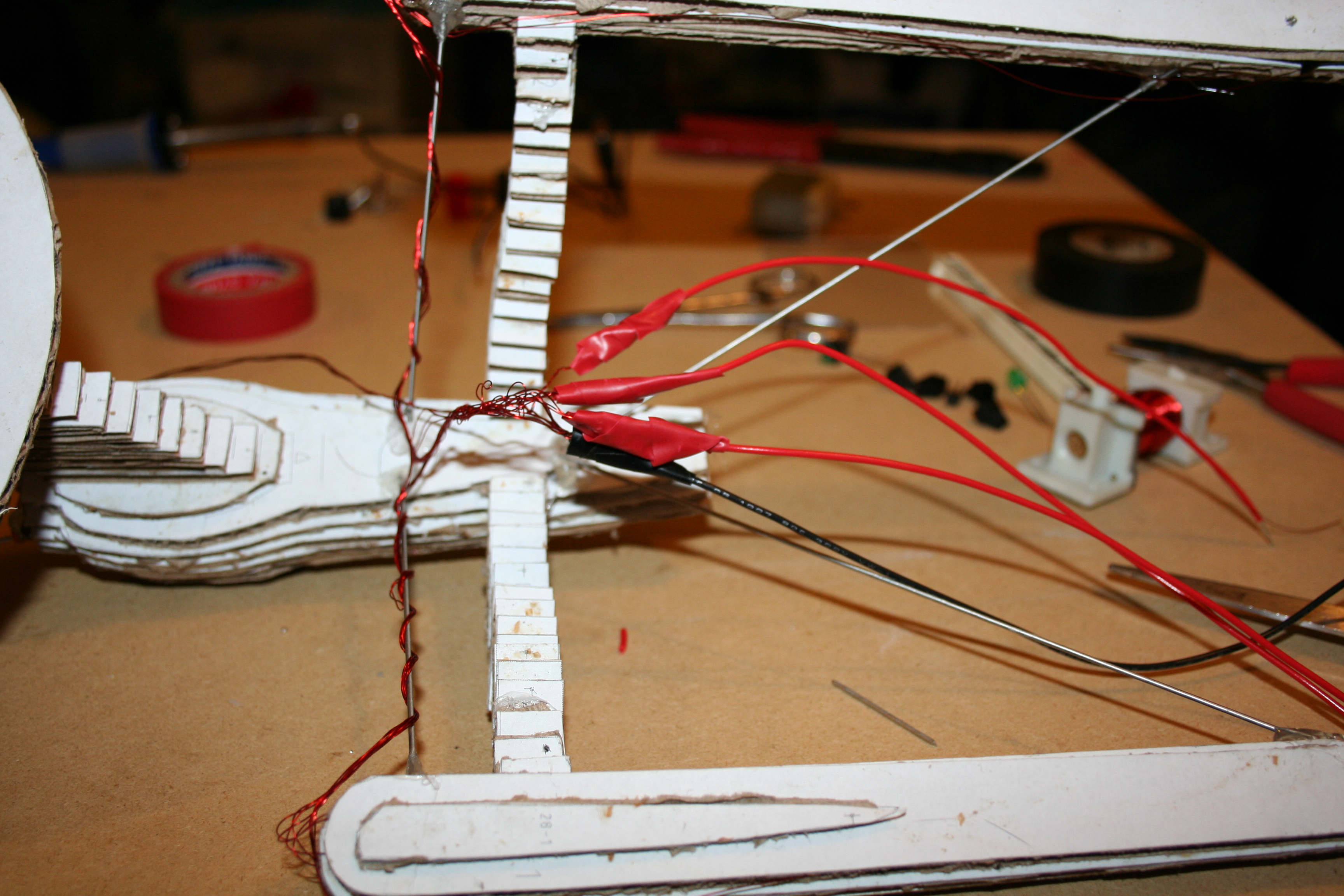
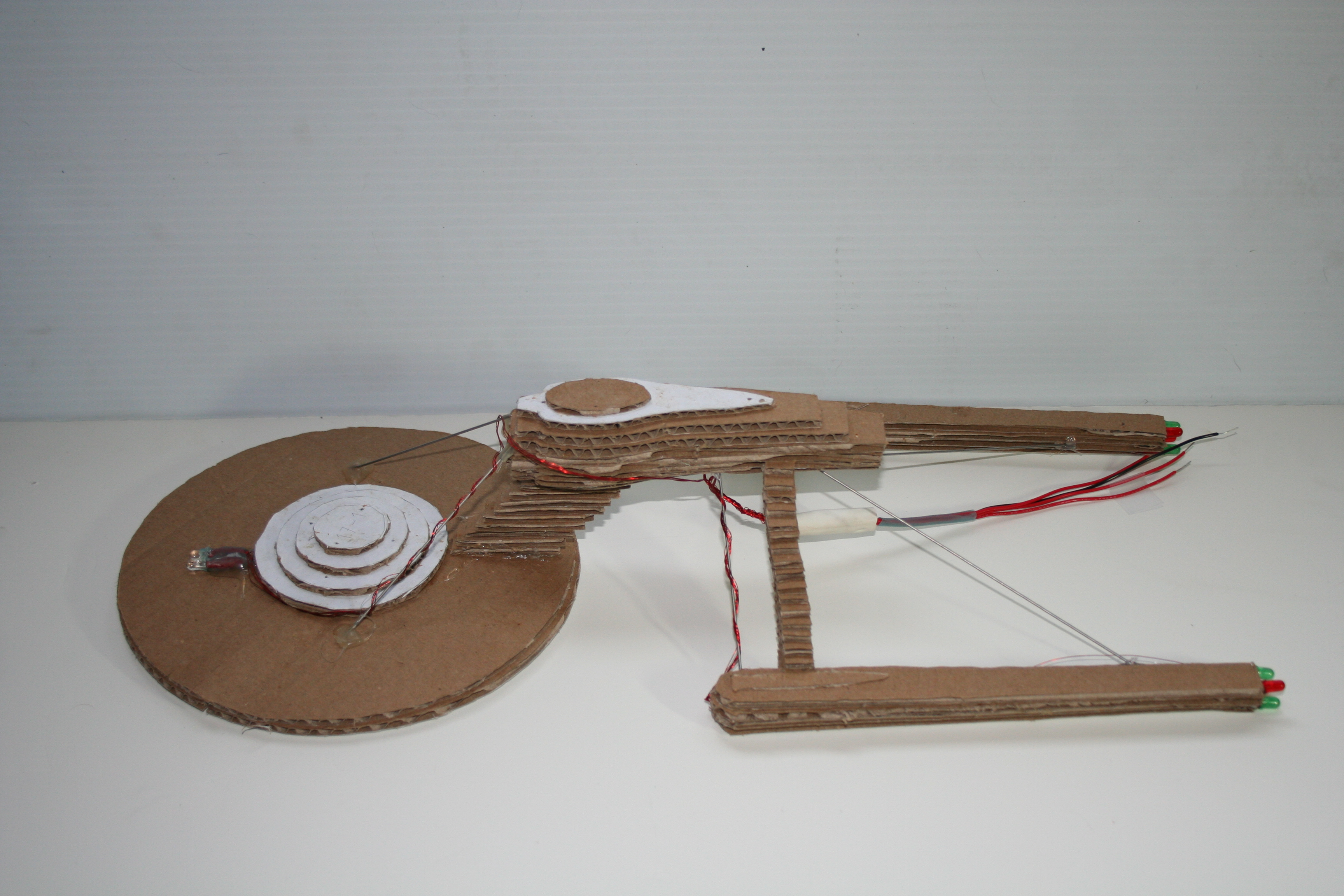
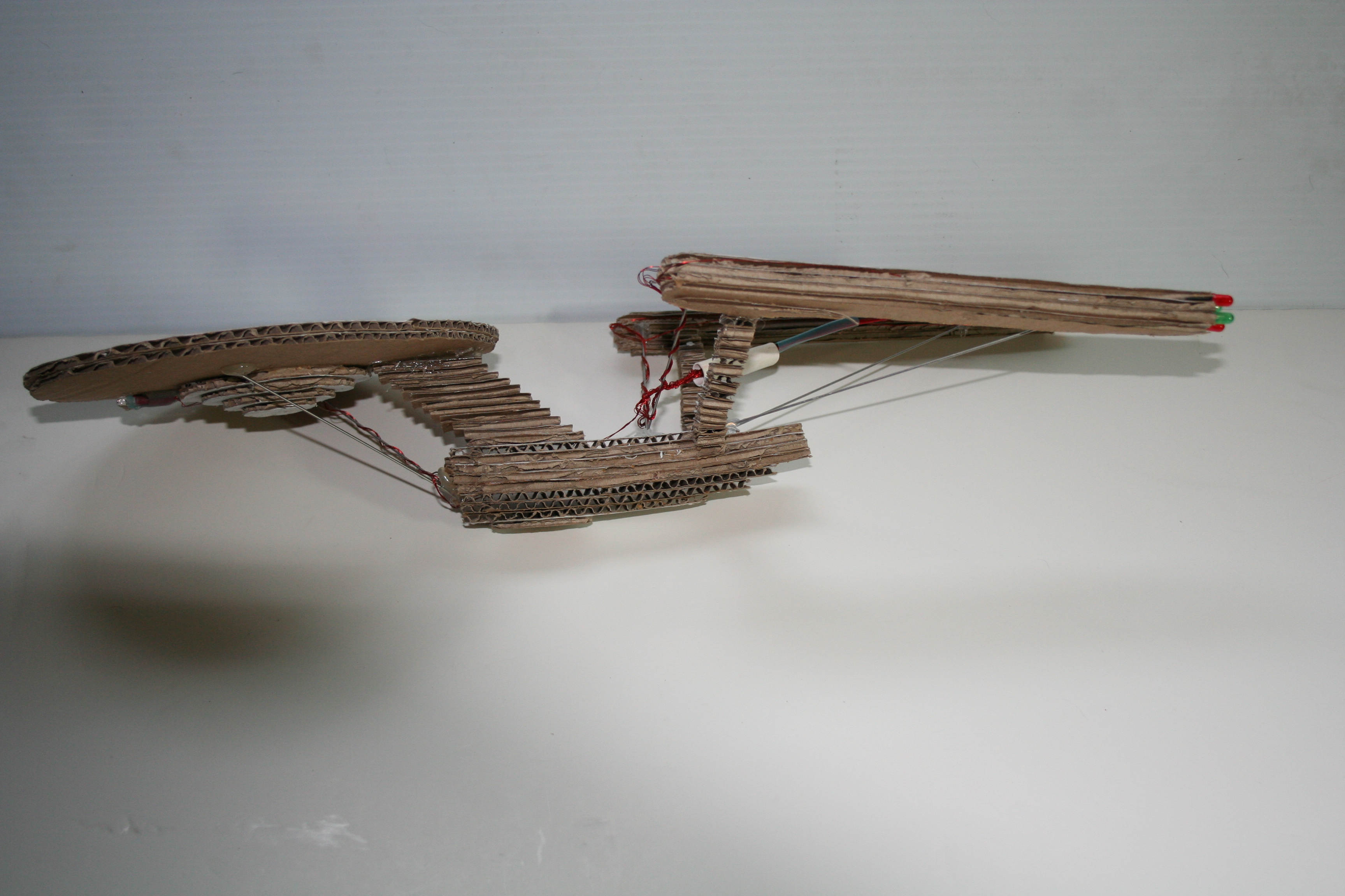
Start by feeding the wires from the LEDs red and green though the engines. Then, hot glue the bright red LEDs on the front of the upper hull. Next, wrap the wires from all the LEDs along the wire supports tho the center of the main body. Now find all the grounds and wrap them together; do the same for the red, green and bright red LED power wires. After that, connect a piece of 22 awg wire to each wire bundle and solder. Finally, wrap electrical tape around each wire bundle.
The Arduino
![IMG_1781[1].JPG](/proxy/?url=https://content.instructables.com/FBD/JRJU/HD8TWS3U/FBDJRJUHD8TWS3U.jpg&filename=IMG_1781[1].JPG)
![IMG_1778[1].JPG](/proxy/?url=https://content.instructables.com/FG7/ED0I/HD8TWS3I/FG7ED0IHD8TWS3I.jpg&filename=IMG_1778[1].JPG)
![IMG_1779[1].JPG](/proxy/?url=https://content.instructables.com/FWQ/VEAL/HD8TWS3J/FWQVEALHD8TWS3J.jpg&filename=IMG_1779[1].JPG)
First, connect one pin of the switch to ground on the arduino and connect the other pin to arduino pin 4. After that, connect the LED ground to the arduino ground and the red LED to arduino pin 3 and the green to arduino pin 2. Finally, connect the two bright red LED to arduino pin 13 and upload the code below.
const int ledPin1 = 2;
const int ledPin2 = 3;
const int ledPin3 = 13;
const int buttonPin = 4;
const int interval = 100;
const int interval2 = 100;
boolean led1State = LOW;
boolean led2State = HIGH;
boolean led3State = LOW;
long previousMillis = 0;
long currentMillis;
long previousMillis2 = 0;
void setup()
{
pinMode(ledPin1, OUTPUT);
pinMode(ledPin2, OUTPUT);
pinMode(ledPin3, OUTPUT);
pinMode(buttonPin, INPUT_PULLUP);
}
void loop()
{
currentMillis = millis();
if((currentMillis - previousMillis)>interval)
{
previousMillis = currentMillis;
led1State =! led1State;
led2State =! led2State;
}
if(digitalRead(buttonPin)==LOW)
{
if((currentMillis - previousMillis2)>interval2)
{
previousMillis2 = currentMillis;
led3State =! led3State;
}
}
if(digitalRead(buttonPin)==HIGH)
{
led3State = LOW;
}
digitalWrite(ledPin1, led1State);
digitalWrite(ledPin2, led2State);
digitalWrite(ledPin3, led3State);
}