USB Powered Camera / Canon PowerShot ELPH Battery Hack
by wpredator in Circuits > Cameras
7364 Views, 17 Favorites, 0 Comments
USB Powered Camera / Canon PowerShot ELPH Battery Hack
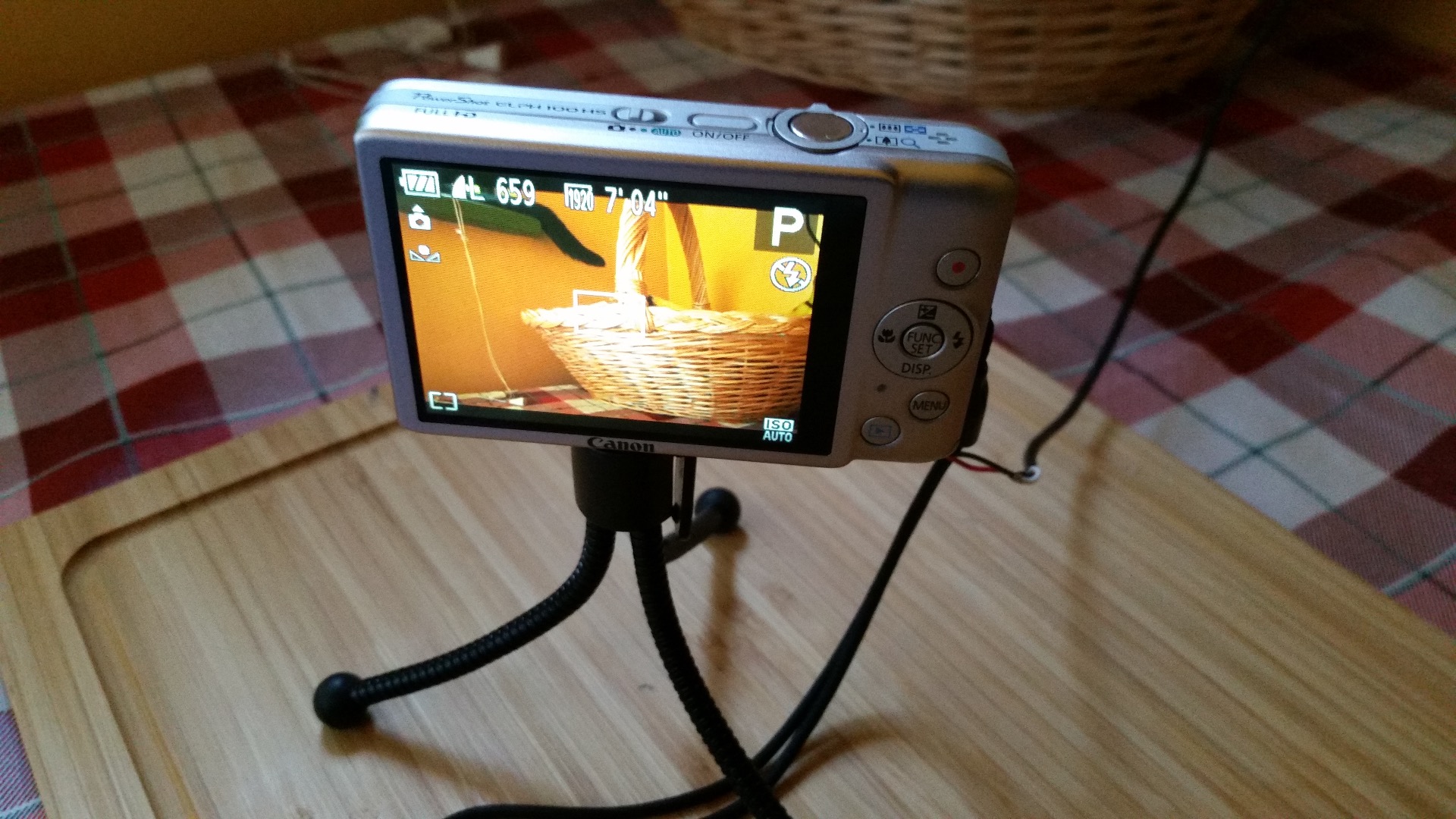
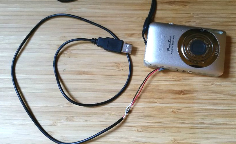
This brief tutorial explains how to hack the battery of a Canon PowerShot in order to power the camera from a USB power supply or an external 5V battery. These Point And Shoot cameras from Canon are pretty cool, especially when hacked with the CHDK firmware to extend their capabilities (like saving raw pictures for instance.) Unfortunately they don't come with a proper power adapter (just a wall charger for the battery) and so, basically, they don't work without the battery plugged in. This battery don't last long enough for the project I have in mind, so I had to figure something out to keep the camera running for a long period of time. This hack will allow you to power the camera with an external battery or a USB power adapter. Please note that this can't work with a computer port because the amount of current required by the camera is about 700mAh. Unpowered USB hubs or cheap USB chargers won't do, either.
Before we start, one piece of advice: please, BE CAREFUL. I can't stress this enough. We are going to disassemble a Li-ion (Lithium-ion) battery which might seem little, light and apparently harmless, but IS NOT, not even when exhausted! These kind of batteries can easily produce a lot of toxic smoke and catch fire when short-circuited. In some instances they can even explode. So be careful. If you can, work outside. I am not responsible for any mistakes you might make that could potentially harm you and the people around you. Also, I am not responsible if you accidentally break your camera.
Requirements:
- 1N4001 diode
- Old USB cable
- Utility knife
- Cutting plier (or nail scissors)
- Multimeter
- Glue gun
- Soldering iron and lead-free solder
- Tweezer
- Electrical tape
Opening Up the Battery
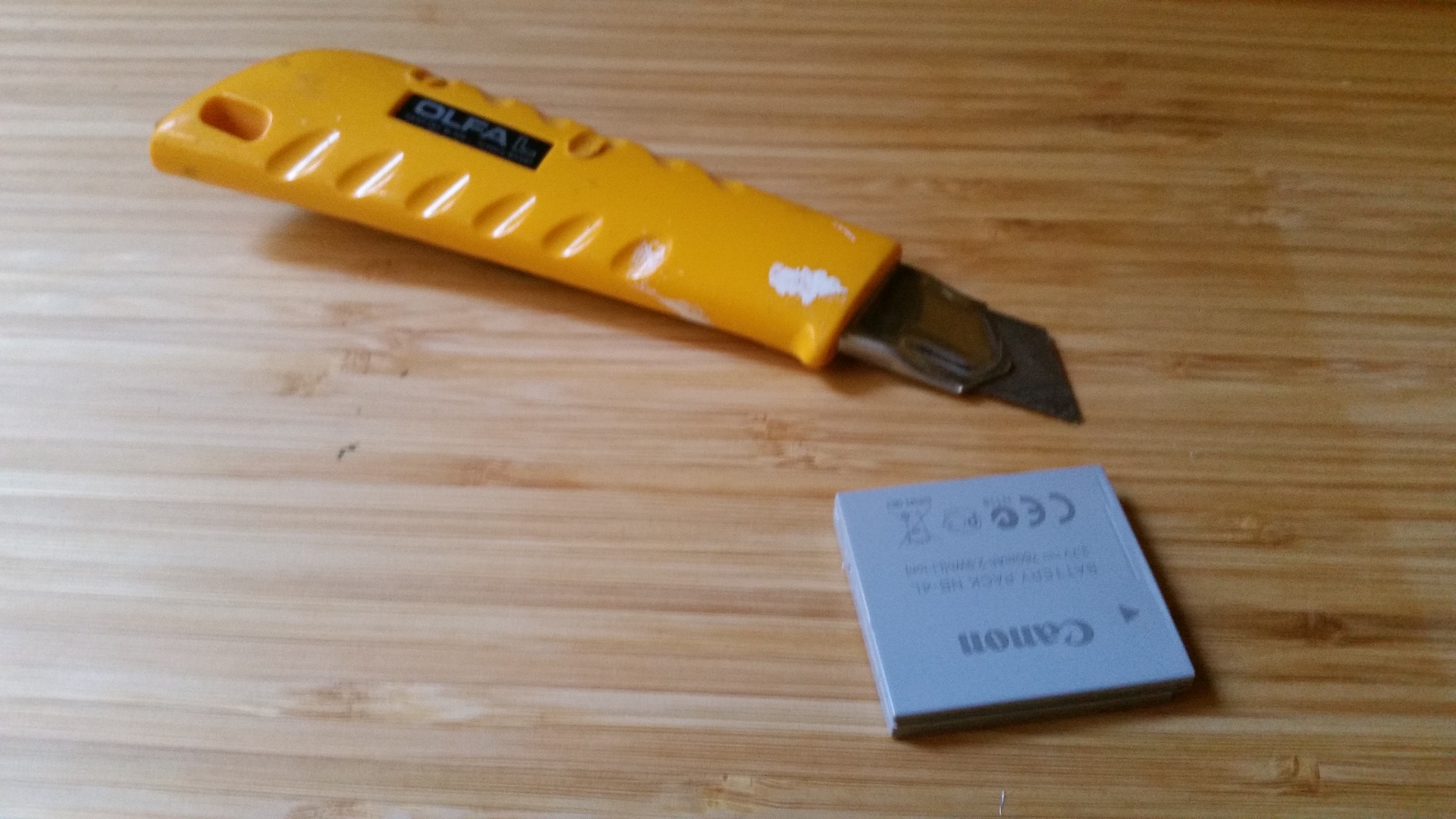
Remove the battery from the camera by pulling the tiny orange lever inside the battery / SD Card compartment. Place the battery on a hard surface (again, try to work outdoor) and check it out before doing anything else. You can see clearly a small indentation running along the side of the battery, that is where you have to cut. Keep away from the small golden contacts on the top / front of the battery: you don't need to cut there. The plastic enclosure is very thin and you don't need to apply a lot of pressure. Just cut gently along the edges of the indentation without damaging the battery inside (it might ignite if punctured!) and being careful not to break the enclosure: we will need all the pieces (except the Li-ion battery, of course) later on. Obviously, you will be very careful not to cut yourself with that utility knife, right?
Separate the Li-ion Battery From the Enclosure
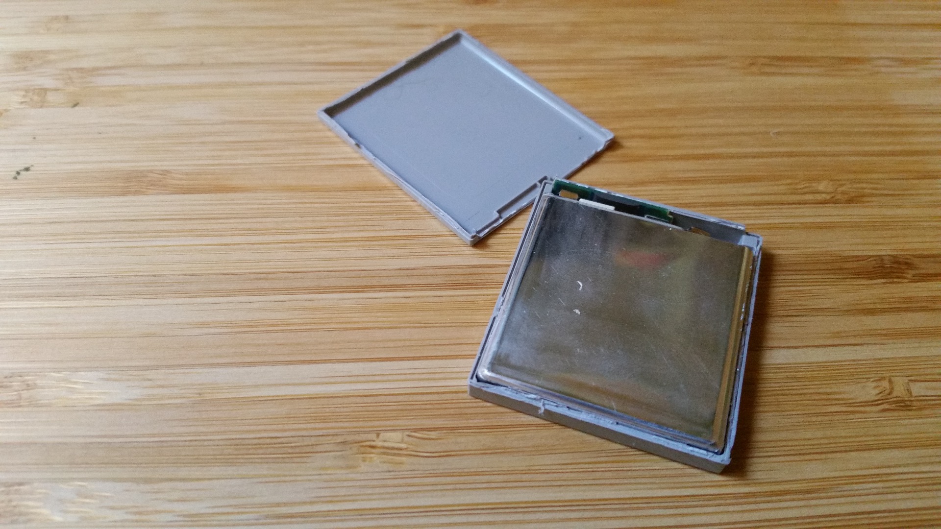
When you are done with the cutting, gently separate the two halves of the enclosure. You will notice that the "lid" comes off easily. The front side isn't cut yet, but that shouldn't be a problem: if you bend a little the "lid" you will be able to fully remove it from the bottom part.
The Li-ion battery is lightly glued to the bottom of the enclosure. With the utility knife try to separate it without tampering the battery's body. Just slide the blade along the edges. Again, stay away from the contacts on the front. Gently pull the battery upwards and remove it from the enclosure without damaging the contacts. If the glue is too strong, you could flip the battery and warm it a bit with an hair dryer in order to loose the adhesive. In any case, don't pull hard or you will break the enclosure. It's weak and flimsy and breaks easily.
Cut the Battery's Terminals
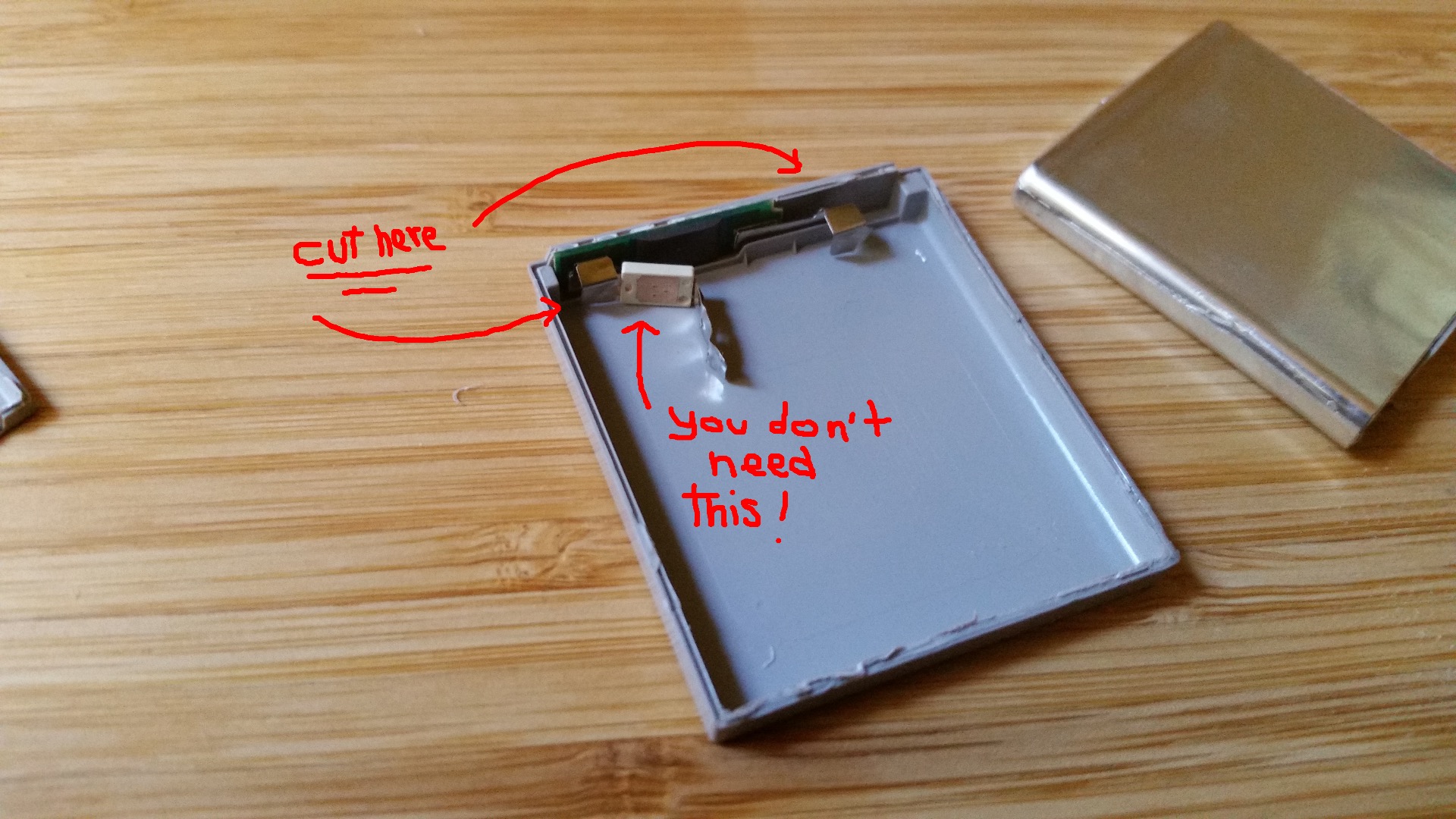
In order to fully separate the battery from the enclosure, you need to cut the battery's terminals. You can do that with a set of nail scissors or cutting pliers. Just be careful not to short-circuit the battery. Dispose the Li-ion battery accordingly. Please remember that it might cause fires so you might want to prevent this by taping it.
This Li-ion battery comes packed with all sort of protections (thermal/current) and you can clearly see those devices connected to the terminals and on the tiny PCB where the contacts are. Simply put, we don't need them, otherwise the camera will sense something wrong and won't work properly nor even power on. The little white thermal (?) protection is quite easy to remove: with a set of nail scissors cut it off. The other one is embedded on the PCB and is impossible to remove. We will deal with this problem in the next step.
Solder the Wires
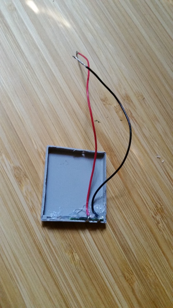
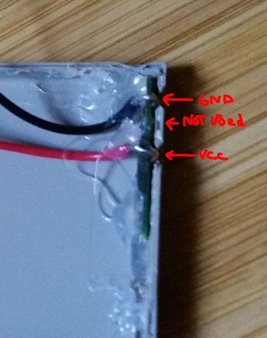
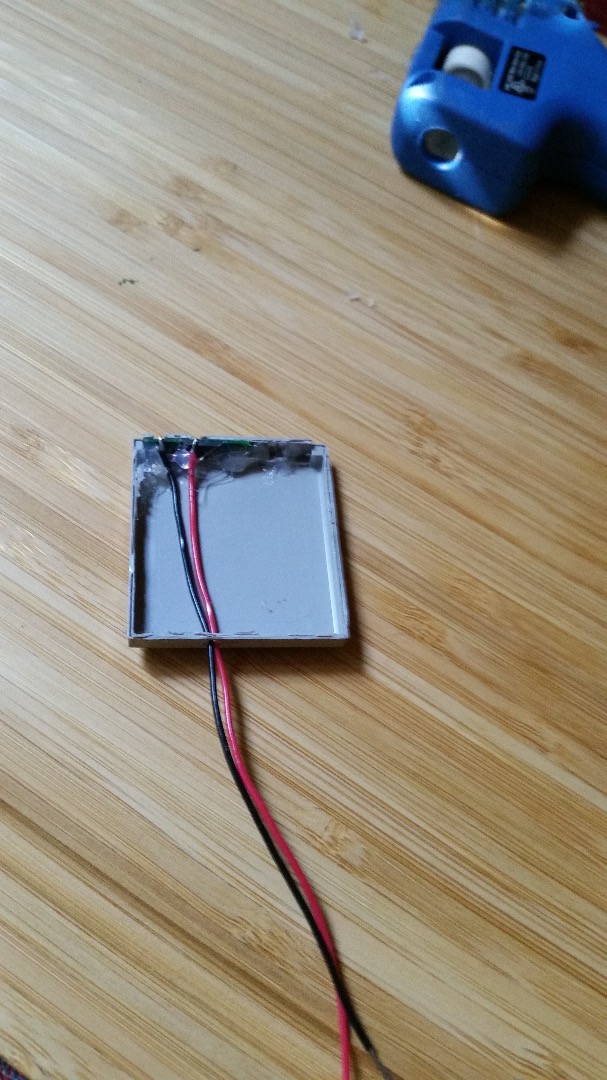
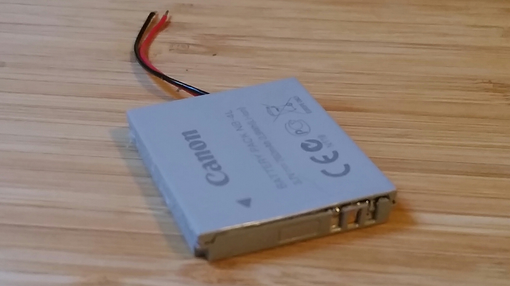
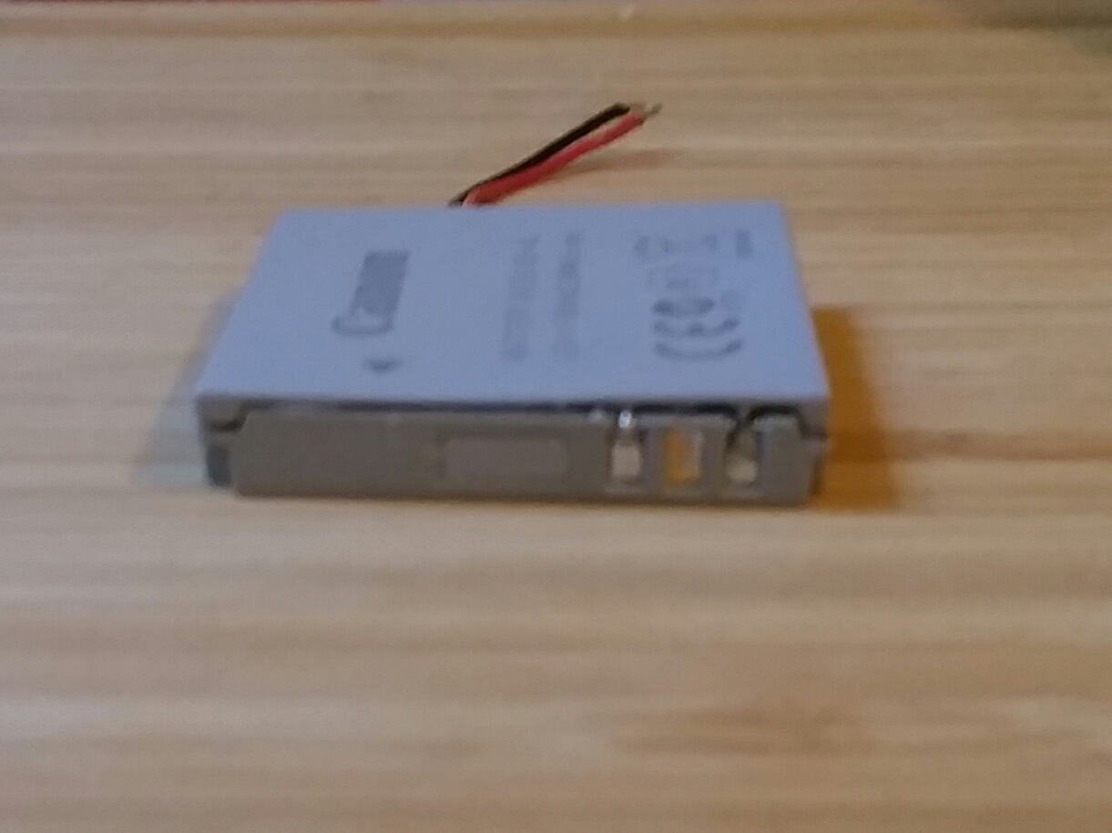
Now you can solder the wires to the terminals (just look at the pictures for the right polarity). Because I couldn't bypass the protection on the PCB in any other ways, I had to solder directly on the contacts themselves! This can be very tricky and requires some soldering skills and a small soldering iron tip. I personally cut short terminals from resistors, made two hooks and soldered one end to the contacts and the other to the wires. Then, with the hot glue gun, I glued the PBC in place carefully aligning it with the holes of the enclosure as shown in the pictures. Just remember, the contact in the middle isn't used. Make a small hole at the bottom of the enclosure for the wires to come out, glue back the lid and you are done. Just try not to glue the outer side of the enclosure otherwise the battery won't slide back into the camera.
REALLY IMPORTANT: You MUST isolate the connector in the middle otherwise the camera won't operate properly. I cut a tiny piece of electrical tape and placed it inside the hole with a tweezer. If the camera turns on showing the message "Change the battery pack", check again the connector in the middle in case the tape fell off and put it back into place.
Add the 1N4001 Diode
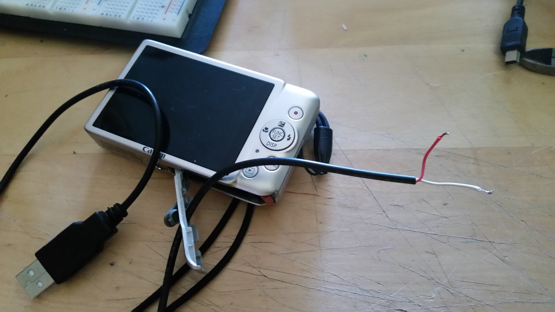
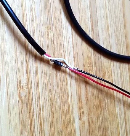
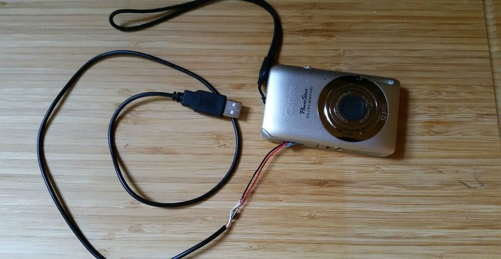
Our power supply or battery outputs 5V but the camera works at 4.3V when the battery is fully charged. I wouldn't try to connect the camera directly to 5V because it might overheat and fry the components inside. By adding a diode in series we cause a 0.7 voltage drop (5V - 0.7V = 4.3V), which is enough to reduce the voltage to a level tolerated by the camera's circuitry. Some purists would frown arguing that this is not the right way to power an electronic device (and they are surely right), but this is what I did and so far my camera, which I have been testing for some time now, works nicely. A better solution would be using a voltage regulator (like a LM317 for instance) to lower the voltage, but this is beyond the scope of this tutorial.
The camera has a hole on battery cover lid as shown in the picture above. You have to remove the little grey cap to uncover the hole. Remember to put the USB cable through the hole before soldering it. If the lid is not firmly closed, the camera won't power on.
Remember that the 1N4001 diode has the Cathode (negative terminal) marked by a gray band. Solder the diode to the red wire with the gray band (Cathode) pointing towards the battery pack as shown in the picture and the positive terminal (Anode) towards the USB plug. Solder the remaining negative wires together and you are done.
Plug the USB connector into a suitable USB power adapter and check with a multimeter the right voltage on the battery's contacts. The polarity is marked on the battery pack so you can't make any mistakes. If it reads something below 5V you are good to go (actually, it might read more than 5V depending on the multimeter and the power adapter used, but it should be fine once there is a load attached to it.) Slide the battery in, close the lid, and turn on the camera. If the display remains black and the "Change the battery pack" message appears, it means that you didn't isolate the connector on the battery pack properly as explained in the previous step or that your USB adapter isn't powerful enough. Get a better one and try again. The camera isn't so picky after all. It requires about 700mAh to operate. I used an Ipad Mini power adapter with success. I then used the one that came with my phone also with success. Again, the USB port of the computer won't power up the camera properly and you might trigger the fuse inside the USB port because the camera is pulling too much current. USB 2.0 ports can only deliver up to 500mAh if not attached to a power adapter. Perhaps a USB 3.0 port could work, but I don't have any at present so I can't say for sure.
Test Your USB Powered Camera
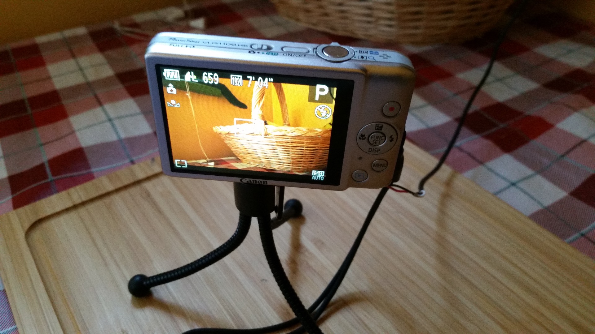
If everything works fine, do some tests like recording long videos at full frame or high speed. This will stress the camera's circuitry enough and warm up a little the diode. But in any case, it should work just fine. At least it works fine for me.
I hope this little tutorial was useful to you. It's part of a bigger project that I have in mind that involves a micro controller (Arduino) and the famous CHDK hack.
If you have any comments (or suggestions,) just let me know. Have fun projecting.
Cheers.