Tutorial to Interface HMC5883L Compass Sensor With Arduino
by mybotic in Circuits > Arduino
89418 Views, 81 Favorites, 0 Comments
Tutorial to Interface HMC5883L Compass Sensor With Arduino
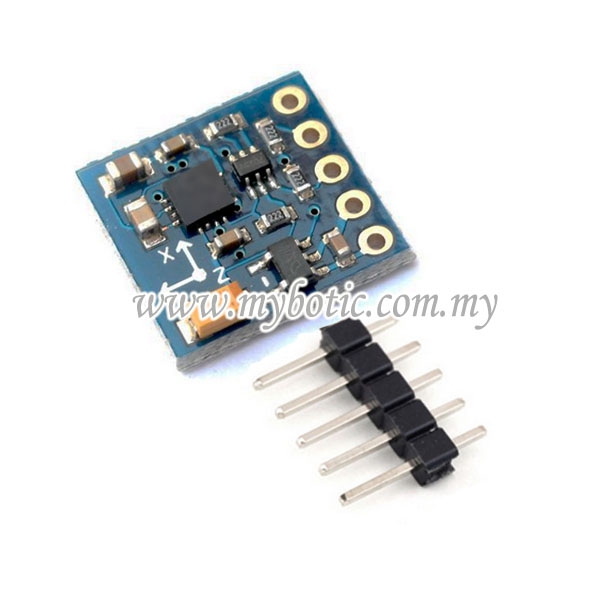
Description
HMC5883L is a 3-axis digital compass used for two general purposes: to measure the magnetization of a magnetic material like a ferromagnet, or to measure the strength and, in some cases, the direction of the magnetic field at a point in space. Communication with the HMC5883L is simple and all done through an I2C interface. There is an on board regulator. The breakout board includes the HMC5883L sensor and all filtering capacitors. The power and 2-wire interface pins are all broken out to a 0.1" pitch header. Uses famous HMC5883L magnetometer chip. Supports 3.0V to 5.0V IO levels on I2C SCL and SDA pins.
Specification
- Power supply :3V - 5V
- IO Voltage Level: 3V - 5V
- Communication: Standard IIC communication protocol
- Module Dimensions: 14.35 mm (L) x 13.16 mm (W) x 3.40 mm (H)
- PCB thickness: 1.60 mm
- Measuring range: ± 1.3-8 Gauss
Materials Preparation
In this tutorial, you will need :
1. Arduino Uno Board and USB Cable.
2. HMC 5883L Compass Sensor
3. Jumper Wires
4. LCD 16X2
5. Breadboard
6. 10K Potentiometer
7. Arduino IDE Software
Pin Description
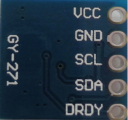
VCC : Power supply
GND : GND power
SCL: I2C Clock Input
SDA : I2C Data IO
DRDY: Data Ready Output
Pin Connection
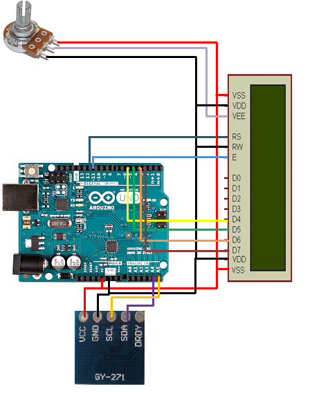
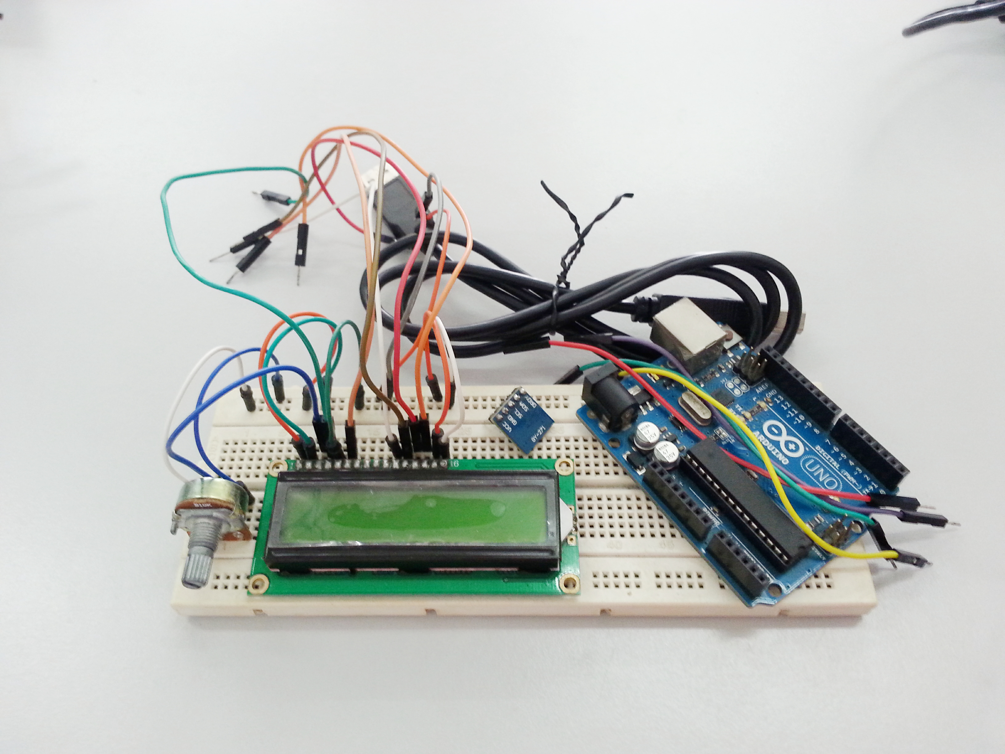
Connect HMC5883L to Arduino Uno Board as following :
- VCC to +5V
- GND to GND
- SCL tO A5
- SDA to A4
Connect LCD to Arduino Uno Board as following :
- VSS to +5V
- VDD to GND
- RS to 12
- RW to GND
- E to 11
- D4 to 5
- D5 to 4
- D6 to 3
- D7 to 2
- A/VSS to +5V
- K/VDD to GND
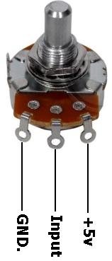
Connect 10K Potentiometer to LCD as following (refer image for potentiometer pinout) :
- GND to GND
- Data to v0
- VCC to +5V
Connect Arduino to Computer
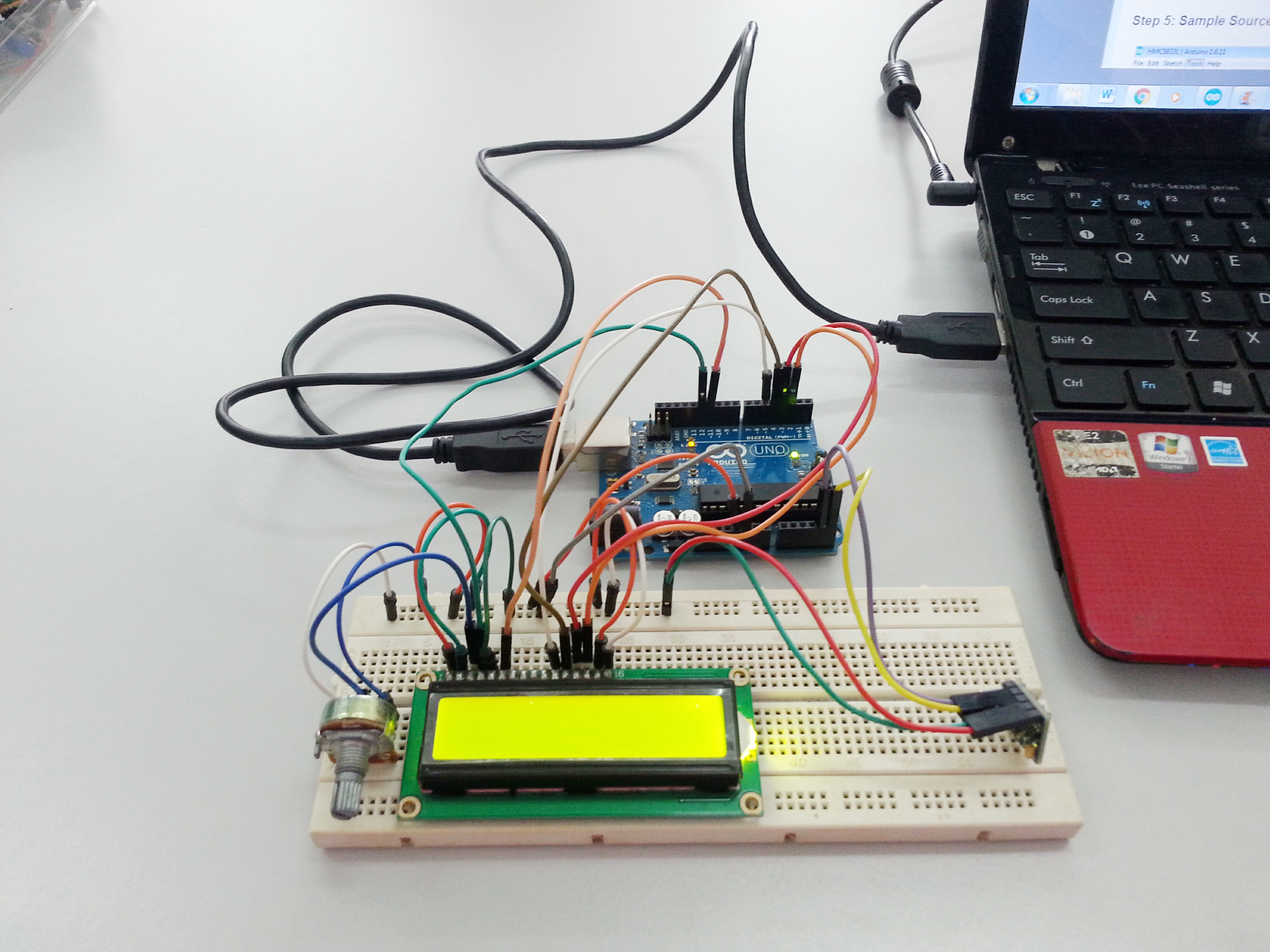
After u have complete your circuit, connect your Arduino Uno Board to your computer via USB Cable. You can see your LCD is on.
Sample Source Code
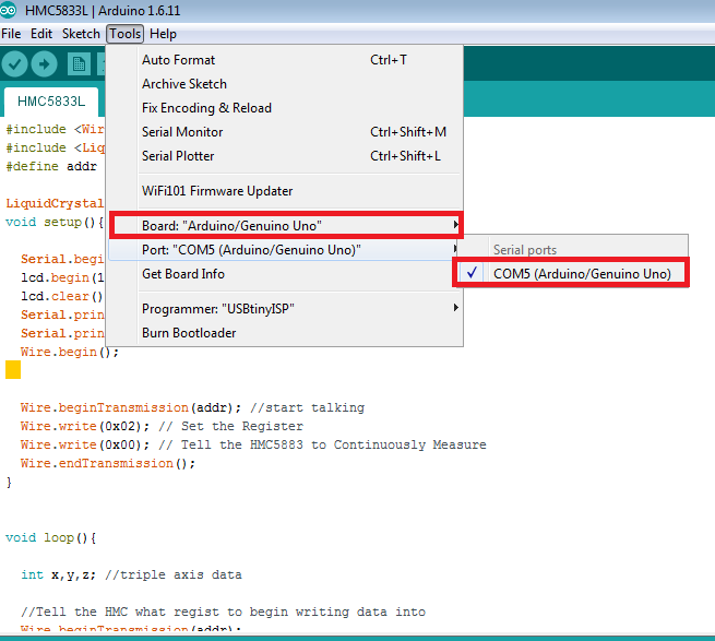
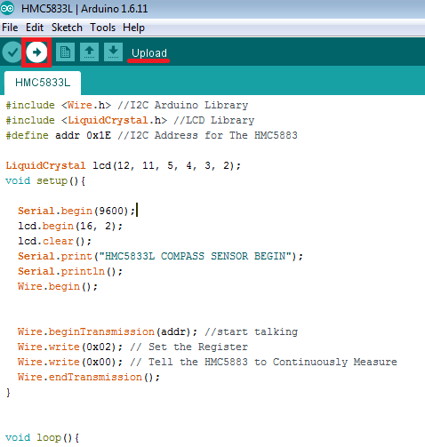
You may download this sample source code and open it on your Arduino IDE. Choose the correct board and port. Then, upload your Code into your Arduino Uno Board.
Downloads
Library
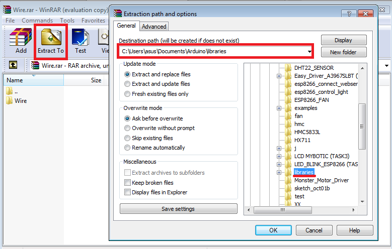
You have to download these libraries before uploading the sample source code into your Arduino IDE to allow Arduino to communicate with LCD and HMC5883L. Download the ZIP file below > Open Zip File > Extract to your Arduino Uno Library folder. Refer the image above for your references.
Corresponding Output
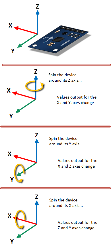
As illustrated, twisting or turning the device will provide the corresponding outputs.
Result : Serial Monitor
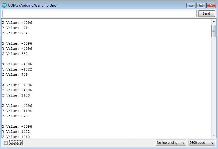
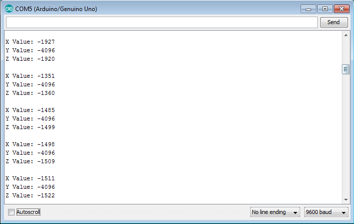
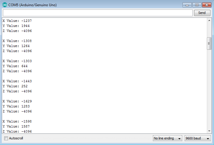
i. when device rotate around it's X-axis, X-axis remain the same while the other two axis changed.
ii. when device rotate around it's Y-axis, Y-axis remain the same while the other two axis changed.
iii. when device rotate around it's Z-axis, Z-axis remain the same while the other two axis changed.
Video
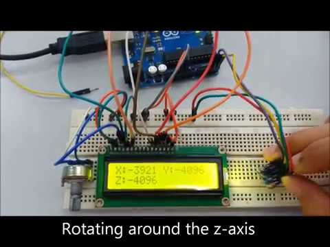
This video shows HMC5883L Compass Module corresponding output when interfaced with Arduino Uno.
News!
HMC5883L not Working!
Try download Library (Mecha_QMC5883L) and source code.