Tutorial: Laser Cutting From Solidworks
by echang777 in Workshop > Laser Cutting
85316 Views, 80 Favorites, 0 Comments
Tutorial: Laser Cutting From Solidworks
This tutorial outlines the process of getting parts from Solidworks to cut on Universal laser cutters.
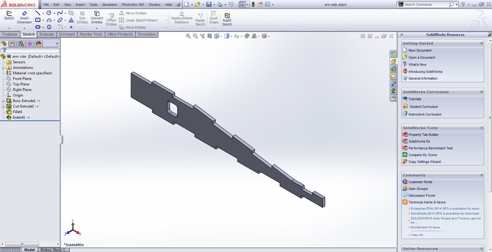
Load Your Part in Solidworks
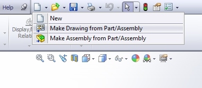
Make a Drawing From the Part
.jpg)
.jpg)
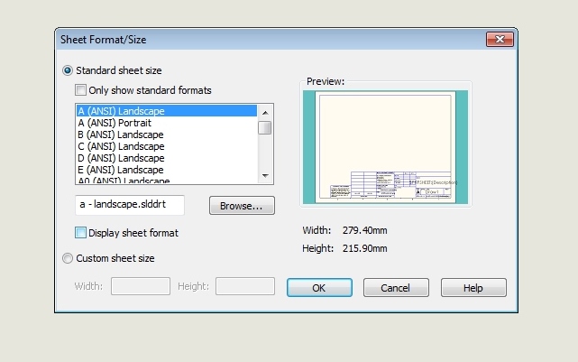
The document size does not matter. To make things easier on yourself, be sure to de-select the "Display Sheet Format" option.
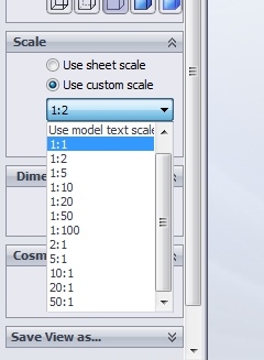
Add the Desired View, and Set Scale to 1:1
.jpg)
This step is very critical. If the scale is not set correctly, your part will not cut at the right size.
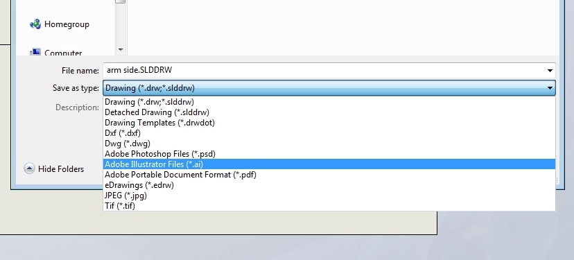
Save the File As a .AI, and Open in Adobe Illustrator
.jpg)
.jpg)
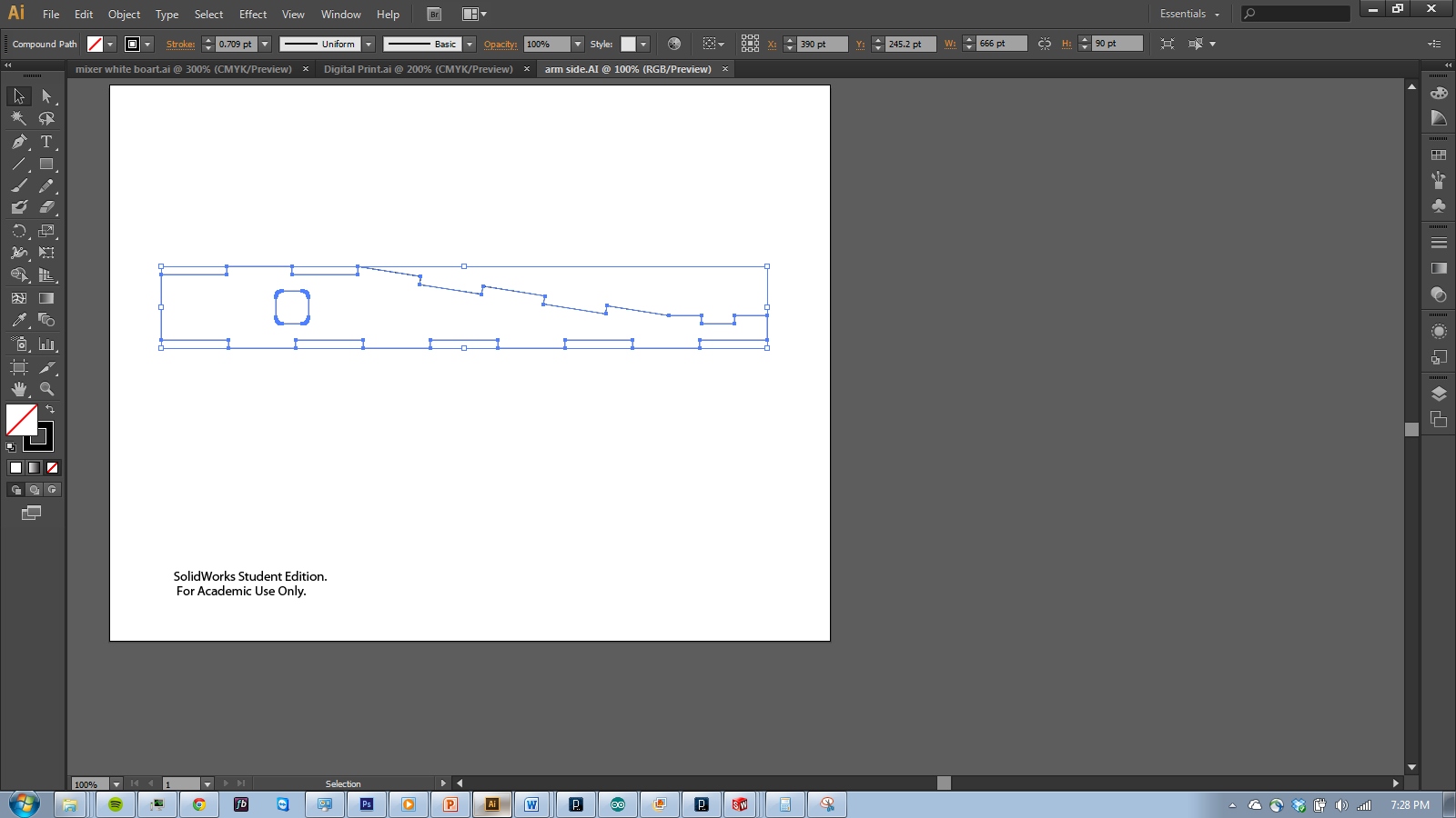
Copy the Part to a New Document
.jpg)
.jpg)
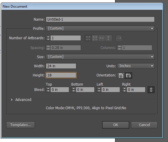
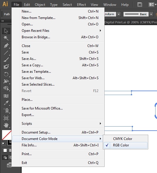
Set the document size to the cut area of the laser cutter. Check to make sure the color mode is RGB.
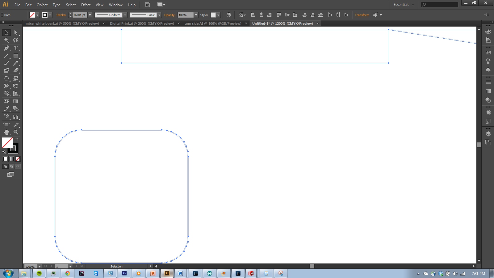
Release Compound Path, and Join Paths
.jpg)
.jpg)
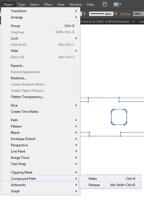
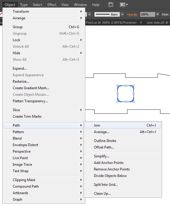
Solidworks applies a compound path to the entire part. Release it, then join continuous sections of your part.
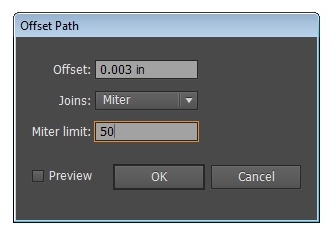
Compensate for the Laser Kerf Using Offset Path
.jpg)
.jpg)
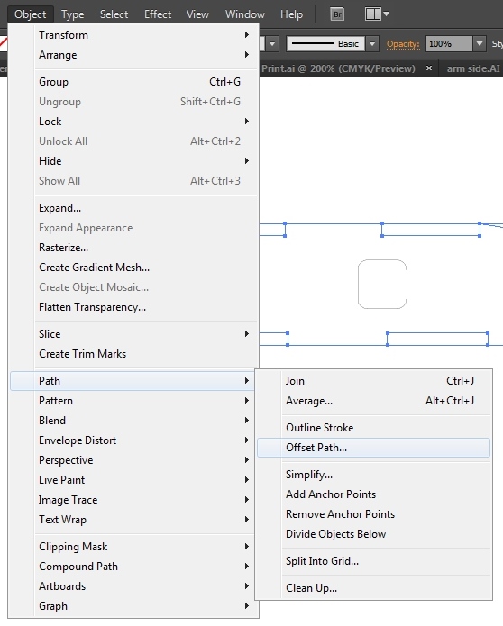
Select all outer paths, and apply the desired offset. For most Universal lasers I've used on material 1/8" or less, I set a kerf of 0.003". Set the miter limit to something large- I typically use 50.
Select the inner paths, and apply a negative offset. In this case, -0.003".
Delete Original Paths
.jpg)
Zoom in, and delete the original paths
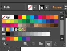
Applied Desired Stroke Color
.jpg)
.jpg)
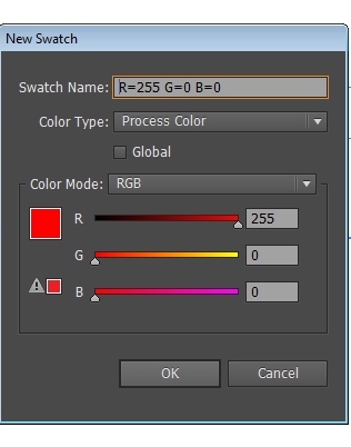
Select your part, and create a new swatch under stroke.
For most Universal laser cutters, R255 G0 B0 indicates a vector cut. Use whatever your cutter requires.
Cut!
Now, you can launch the print driver to send the cut to the laser cutter.