Turn a Broken Mac Classic Into a Modern-day Raspberry Pi Computer
by officialnerdhut in Circuits > Raspberry Pi
6705 Views, 9 Favorites, 0 Comments
Turn a Broken Mac Classic Into a Modern-day Raspberry Pi Computer
Well, this might not be useful for everyone, because most of you probably don't own a broken classic Mac. However, I really like the display of that thing and I successfully connected it to a BBB years ago. However, I was never able to display the contents of the framebuffer. But the Raspberry Pi, and its built-in DPI, allow you to connect virtually any external monitor and use it to conveniently display the video output.
Note that this is a simplified copy of the original article published on my personal website. The original version discusses a few more technical details and problems I had during this project.
Supplies
You'll need:
- A technical datasheet of your display
- A 40-Pin Raspberry Pi (2B+ or newer)
- Any (at least somewhat) standard monitor
- Optional: 3.3V to 5V logic level converter (depends on your monitor)
- Wires
Find the Timing and Signal Information
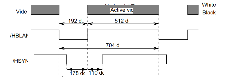
This is probably the hardest step of the whole project because users-manuals usually don't contain this information. I think it's best if you start by searching for technical manuals or repair manuals of your monitor. If your monitor is a standard VGA display, you can look up the timing information online.
Anyway, the timing diagram of the Macintosh Classic's internal CRT is displayed. Luckily, someone uploaded the old developer notes, which contain all sorts of technical details for that computer. I'll discuss the exact timings in a later step of this instructable.
If you don't know how VGA signals (or this Mac's display signal) work, you can take a look at these resources:
About the DPI Mode
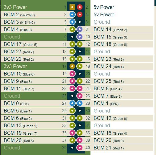
You might have seen some Raspberry Pi display HATs that only connect via the GPIO interface. Those use the DPI mode of the 40-Pin GPIO Raspberry Pi, which is one of the alternate functions of the GPIO.
In that case, the pinout of the GPIO bank changes. The result can be seen in the image (image source).
This configuration allows parallel RGB displays to be attached to the Raspberry Pi GPIO. However, this also means that most of the GPIO pins can’t be utilized for other tasks while the Pi operates in the DPI mode.
This interface is controlled by the GPU firmware and can be configured with special config.txt parameters. Furthermore, you’ll also have to load and enable the correct Linux Device Tree overlay.
Eabling the DPI Mode
As mentioned, the mode is enabled by loading the correct Linux Device Tree overlay. But first, you’ll have to disable I2C and SPI, because those will conflict with some of the video pins. To do that, edit the config.txt file:
sudo nano /boot/config.txt
In that file, comment out the following two lines:
dtparam=i2c_arm=on
dtparam=spi=on
Once that’s done, put the GPIO in the Alt2 mode by loading the DTO:
# 24-Bit mode
dtoverlay=dpi24
# 18-Bit mode
# dtoverlay=dpi18
The mode depends on your monitor. I used the 8-Bit mode, where each color (red, green, and blue) has eight separate bits that transmit the color information to the monitor. Note that both DTOs are already installed by default.
Configuring the Video Hardware
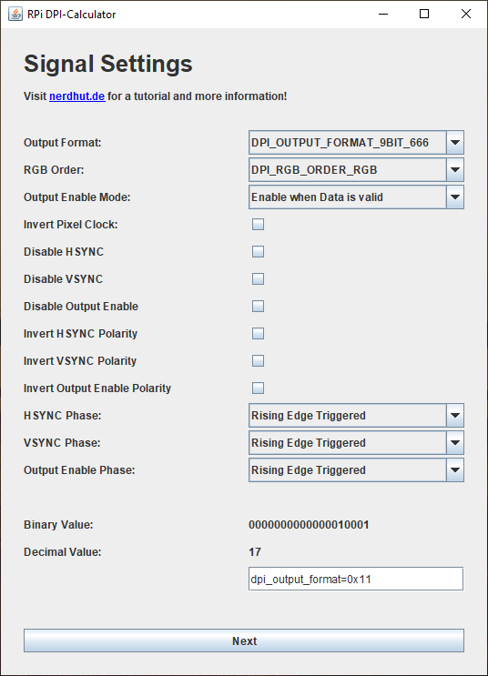
The DPI mode can be configured by placing special attributes in the config.txt file. I wrote this small Java application that'll allow you to quickly enter all the necessary information. It will then generate the attributes for you, and you only need to add them to the config.txt file.
This tool is universal and can also be used to create the configuration properties for other displays. The various fields and parameters are explained on the app's download page. I used the following two attributes for the Macintosh Classic CRT:
dpi_output_format=0x76017
dpi_timings=512 0 14 178 0 342 0 0 4 24 0 0 0 60 0 15667200 1
Configure the Framebuffer and Setup a Custom Video Mode
You can either use a pre-configured timing mode, or define a custom one. In this case, no standard video-mode could be used to interface the display. Therefore, I had to define a custom video mode, which can be done by setting the following two flags in the config.txt file:
dpi_group=2
dpi_mode=87
This will make sure that the dpi_timings parameter, described above, is used by the driver when the Raspberry Pi boots up.
Next, the framebuffer has to be configured. I used the following settings for the Mac Classic CRT:
overscan_left=0
overscan_right=0
overscan_top=0
overscan_bottom=0
framebuffer_width=512
framebuffer_height=342
enable_dpi_lcd=1
display_default_lcd=1
The last two lines will make sure that the video signals get generated and that the DPI is used to output the contents of the frame buffer.
The overscan values can be used to center the image if it should be off-center. However, mine was fine right away, so I didn't use those values.
Hooking Everything Up
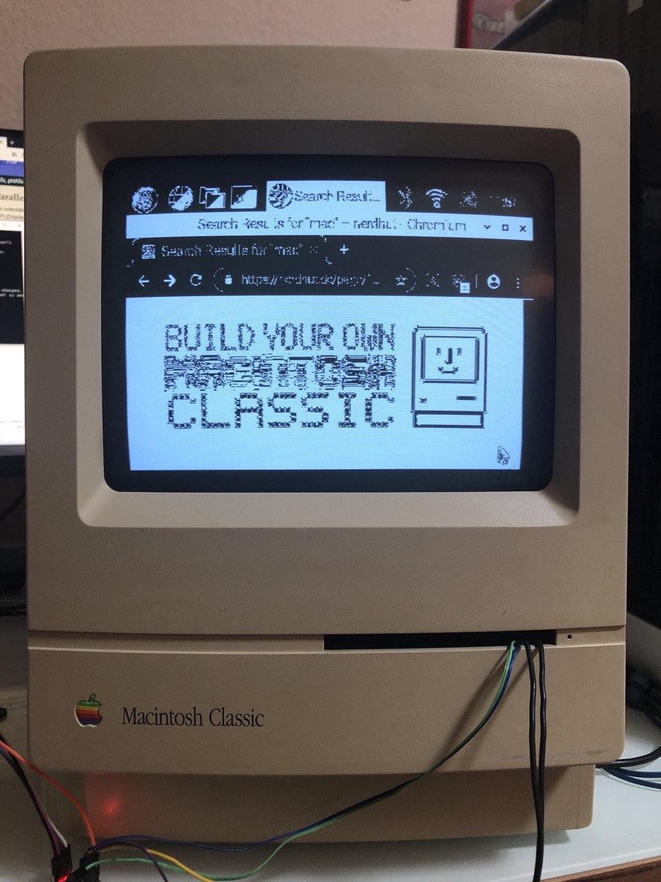
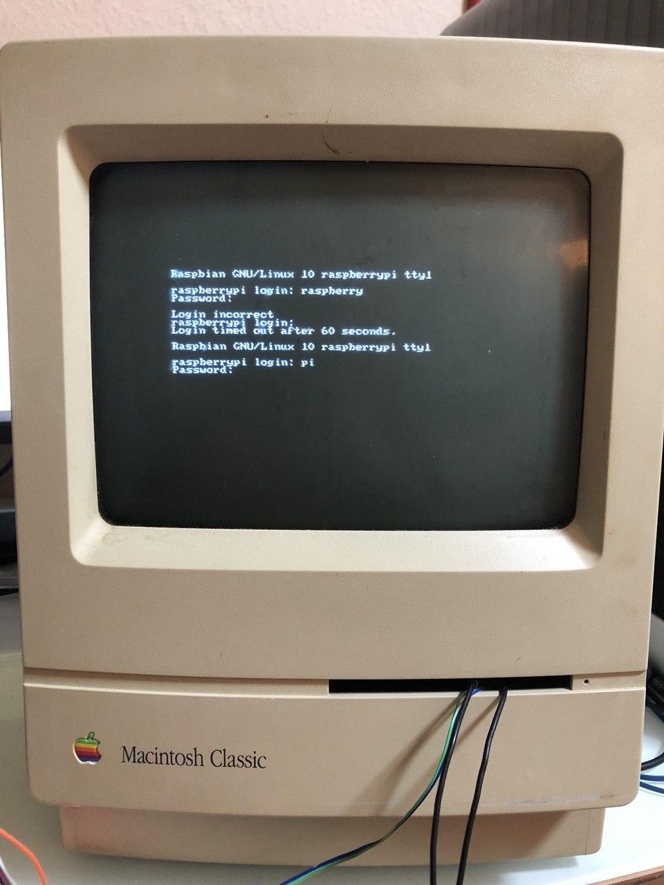
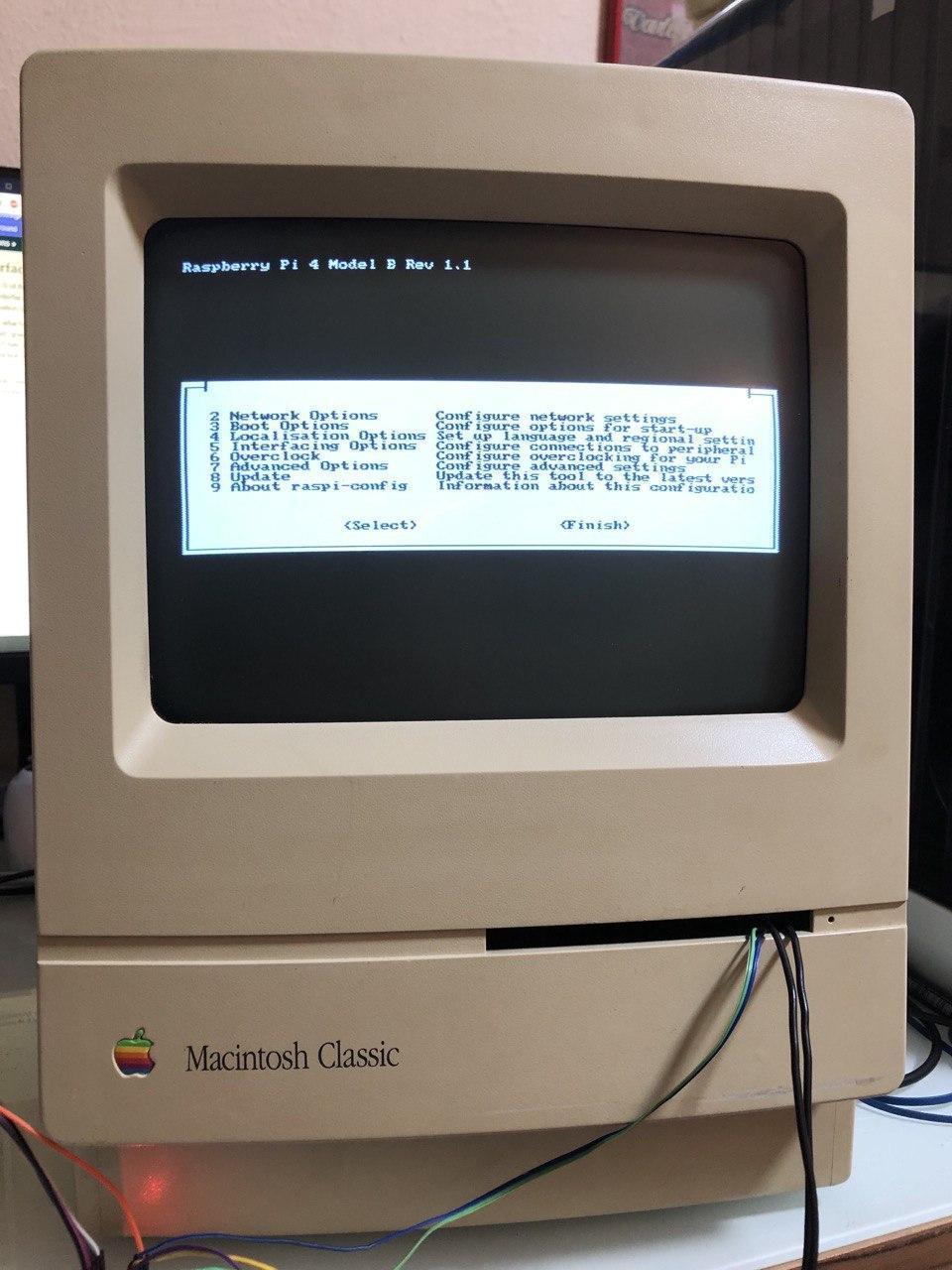
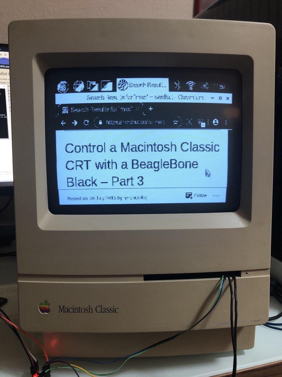
This step is fairly simple. Just connect the HSYNC line of the Raspberry Pi (GPIO 5) and the VSYNC line of the Pi (GPIO 3) to the HSYNC and VSYNC lines of the display. Don't forget to connect a ground wire of the display to a GND pin on the Pi. Then, connect the color lines of the Raspberry Pi to your display. This step varies, depending on your configuration and display.
The Mac Classic's display is a one-bit monochrome display, so I simply used a single color line to connect the data-line of the screen. That's a quick and dirty solution and I'll properly hook the screen up in another article.
Summary
And that's all you need to do! This turned my old broken Macintosh Classic into a cool and useful display piece. Luckily, it's very easy to set up the DPI mode and configure it to work with almost any display, even 30-year-old CRTs. This method allows me to render the desktop and the console output without any complicated programs and hardware modifications.
Note: A few details were omitted from this instructable to keep it short and easier to understand. The full article can be read on nerdhut.de!