Turn Your Old 3dprinter Into a REMOTE 4 AXIS CAMERA HEAD SLIDER
by dslrdiy in Circuits > Remote Control
8269 Views, 86 Favorites, 0 Comments
Turn Your Old 3dprinter Into a REMOTE 4 AXIS CAMERA HEAD SLIDER
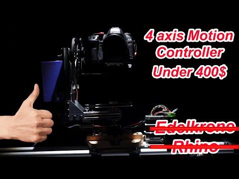
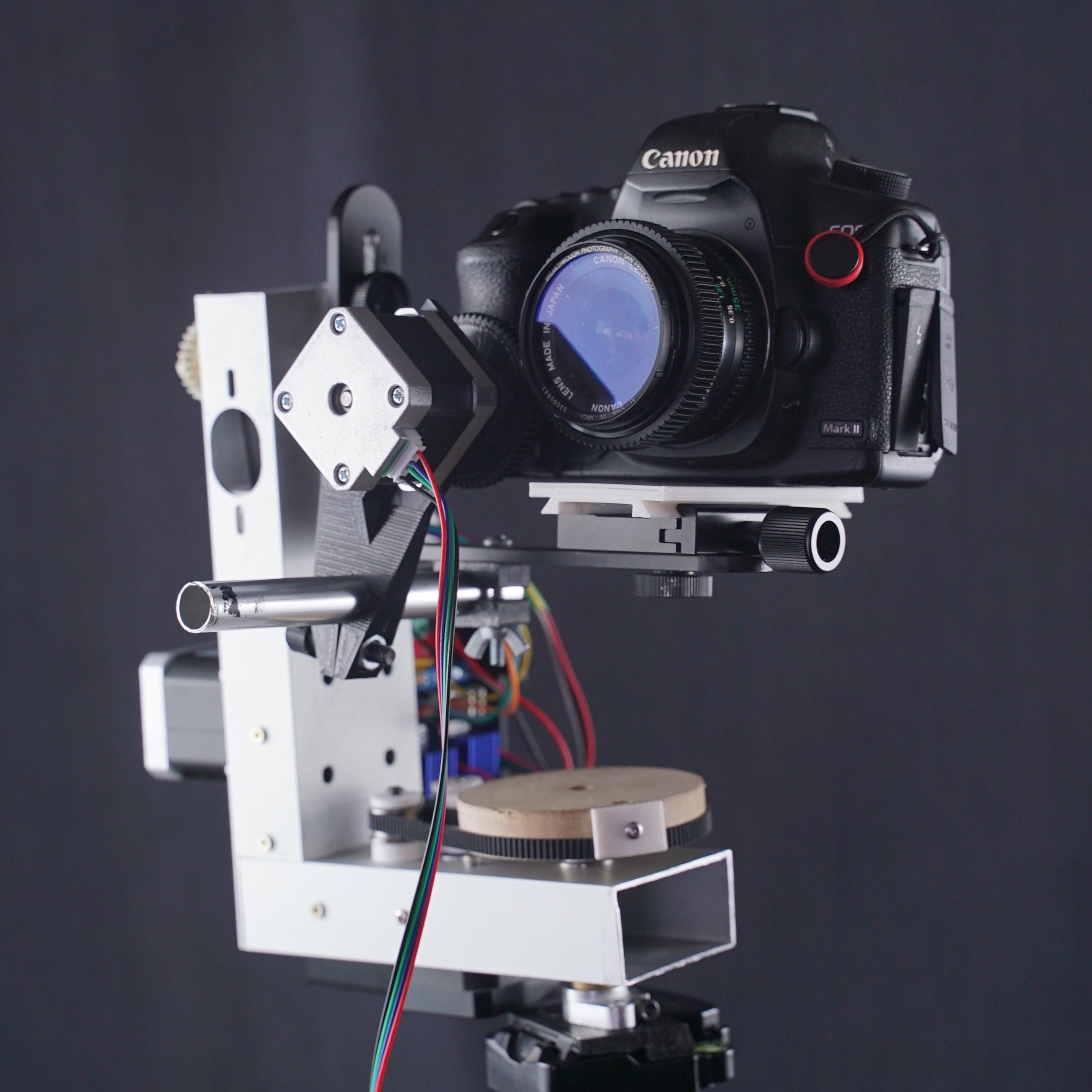
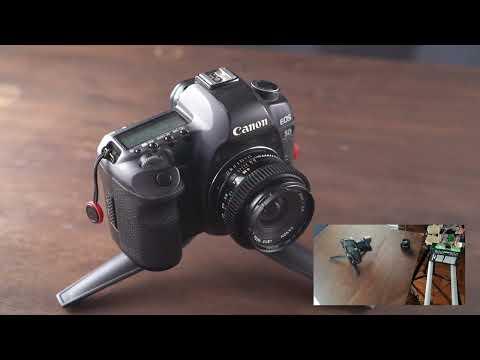
I used to had two 3d printers, one I build my self long time ago with scrap material and a new one from a commercial brand, I do not print quite often so one printer was extra, so I decided to turn it into a 3-4 axis camera head slider. The process is pretty simple just reprogramming the 3d printer to use it as a robot and programming easily a controller that you can remote control as well using your phone. All that help me to record and make videos alone without a camera operator.
Supplies
Old 3D printer with mainly the next parts.
- 3 or 4 Stepper motors the bigger the stronger.
- Controller board of the 3d printer
- 2020 Aluminum Extrusions
- Right Angle Plate
- 8mm Shaft Bearings
- 8mm shaft Supports
- 2 Set of gt2 20 teeth pulleys and gt2 60 teeth pulleys
- Vslot M8x10 screw set
- 8mm Steel rod
- 16 - M3 screws
- Camera L bracket
- 2 Camera long quick release plate
Remote Controller Parts:
- ESP32 board
- OLED Display
- Mini Joystick Module
- Logic Voltage adapter Board
- Arduino Buzzer Module
- 2-M3 Screws
Tools:
- Metal Saw
- Drill with 5mm or 13/64" bit
- Set of Allen Keys
- 1/4 Tap screw set (optional)
- Tap Wrench (optional)
Assemble the Pan Tilt Head
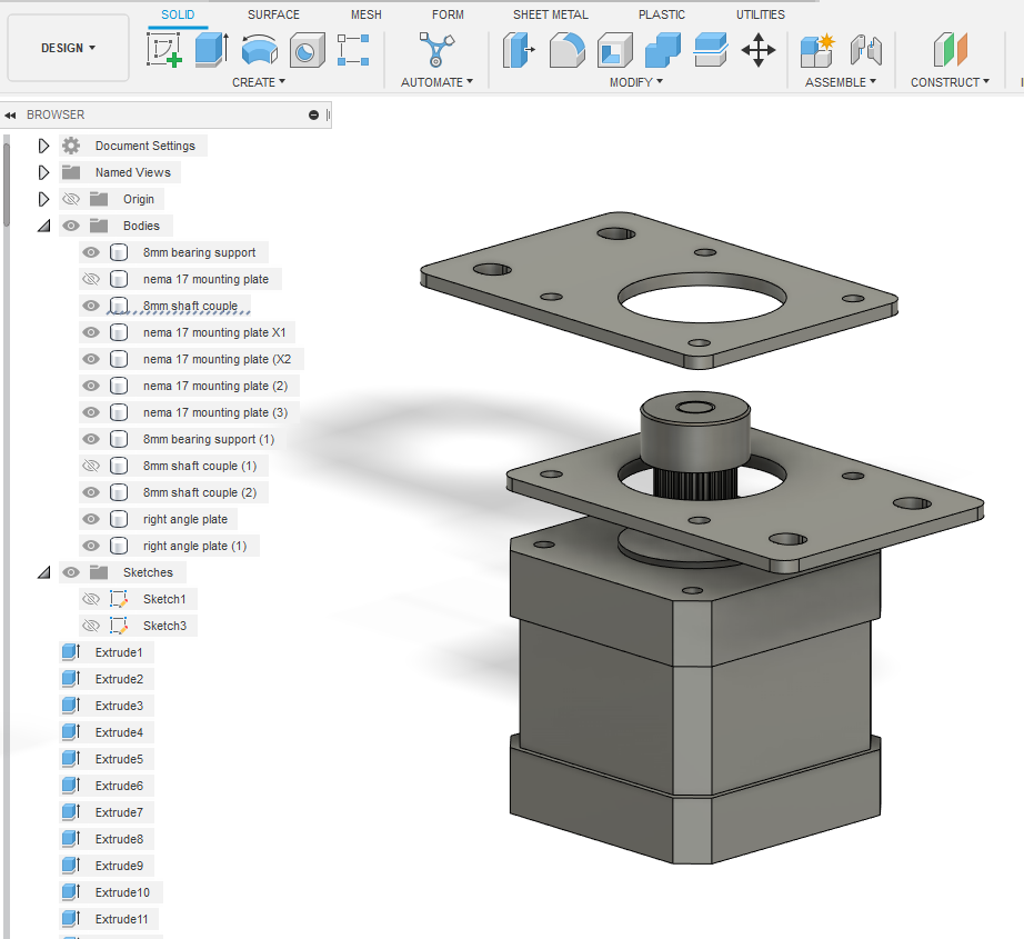
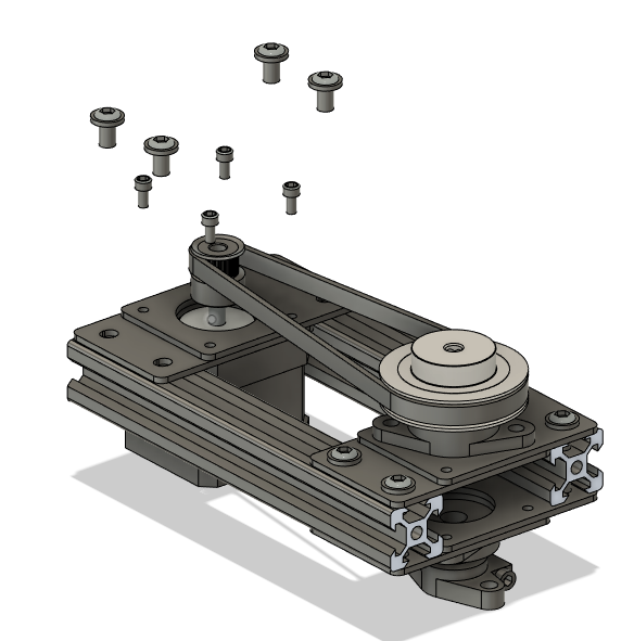
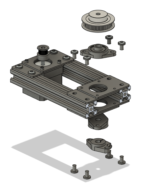
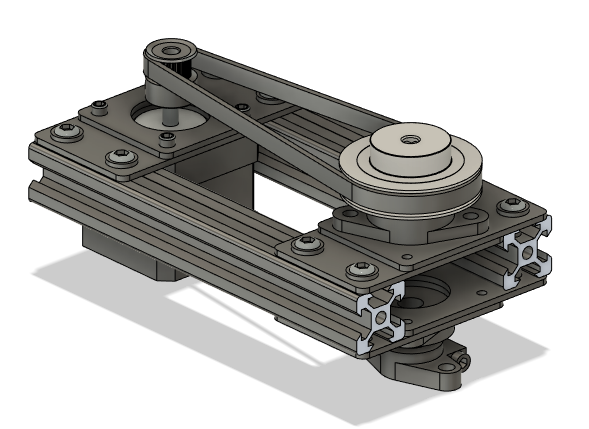
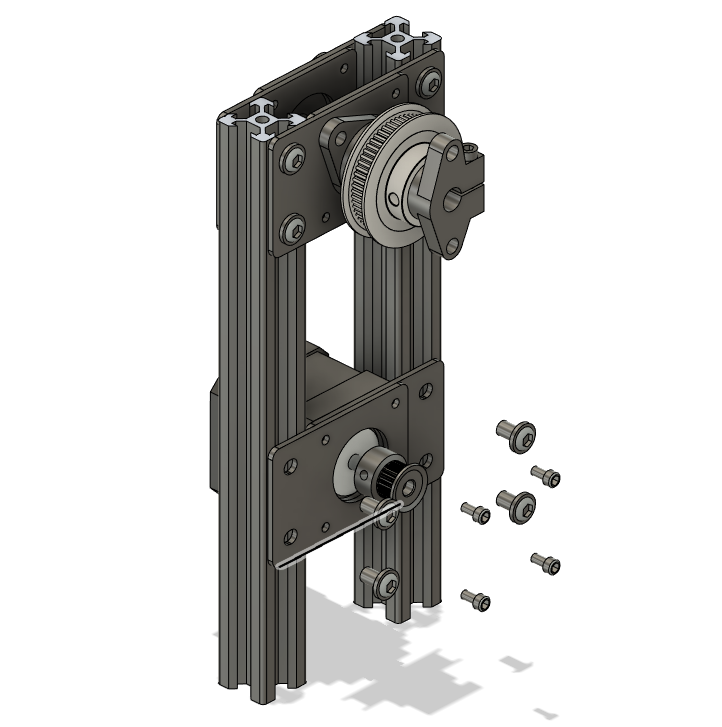
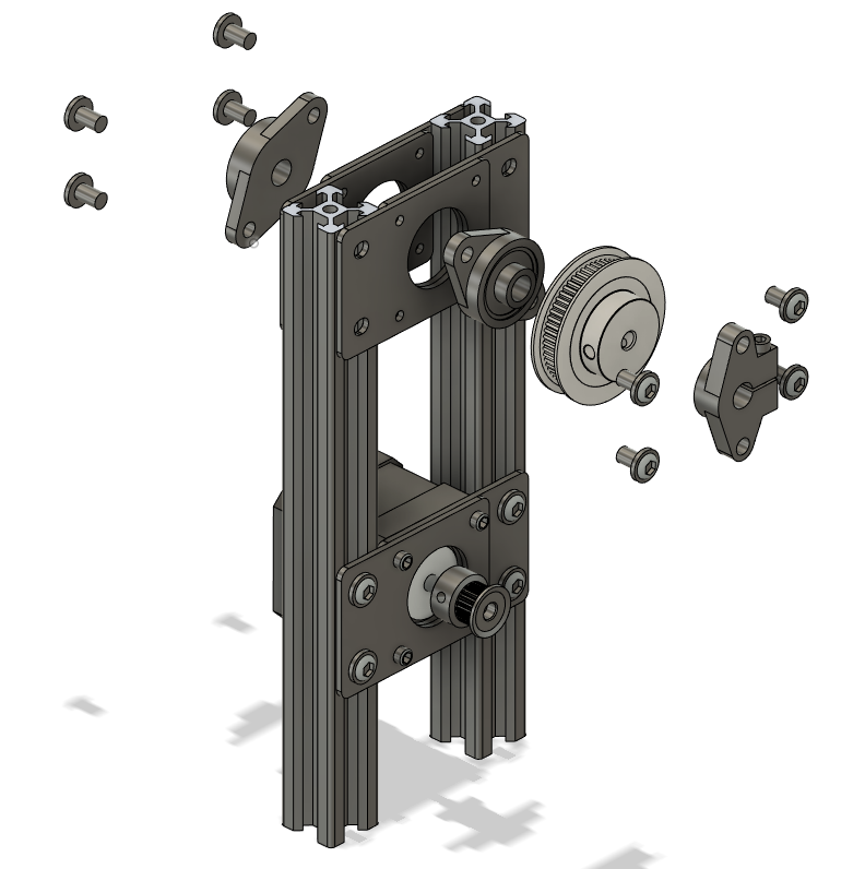
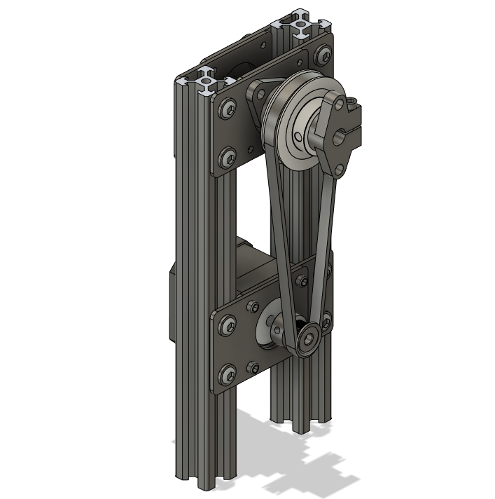
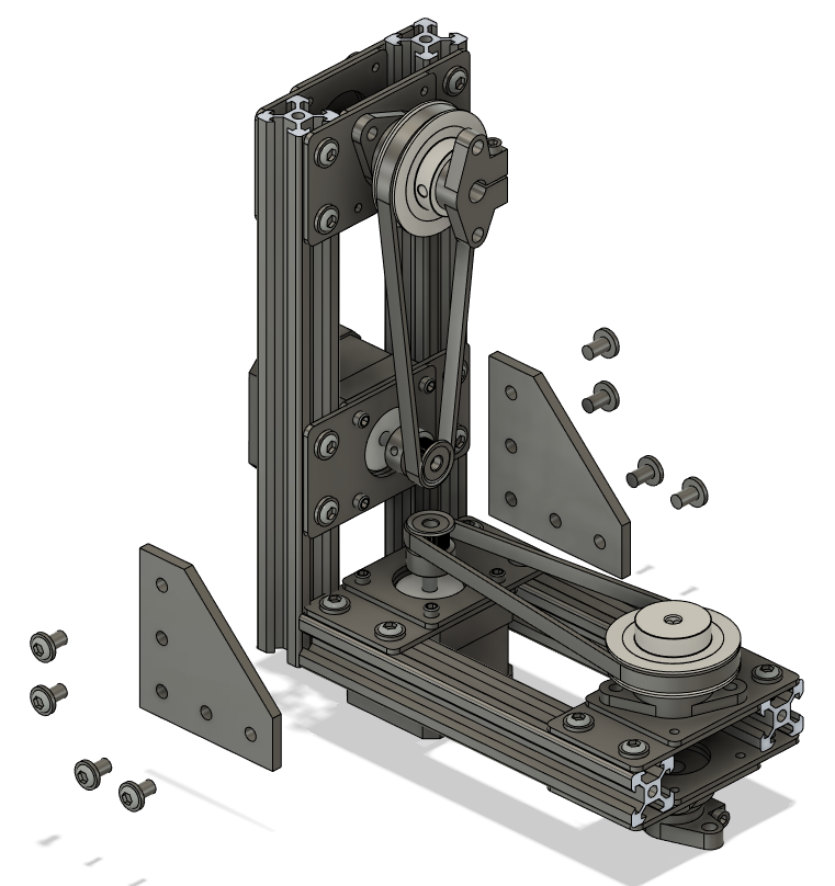
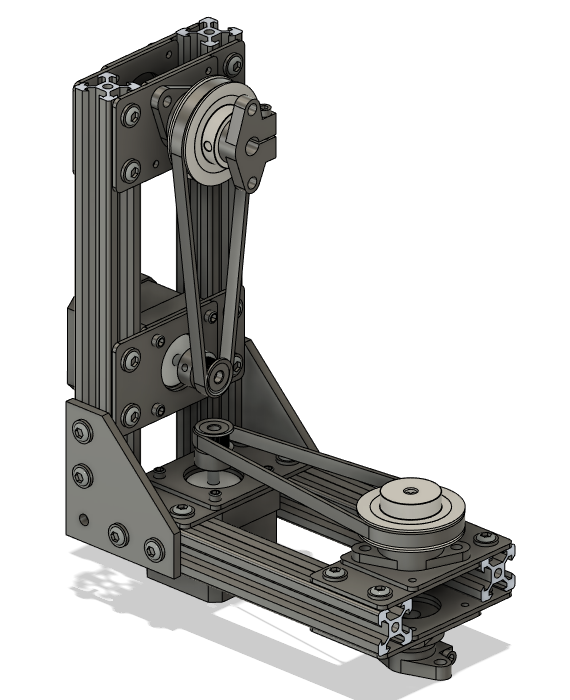
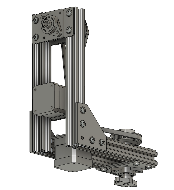
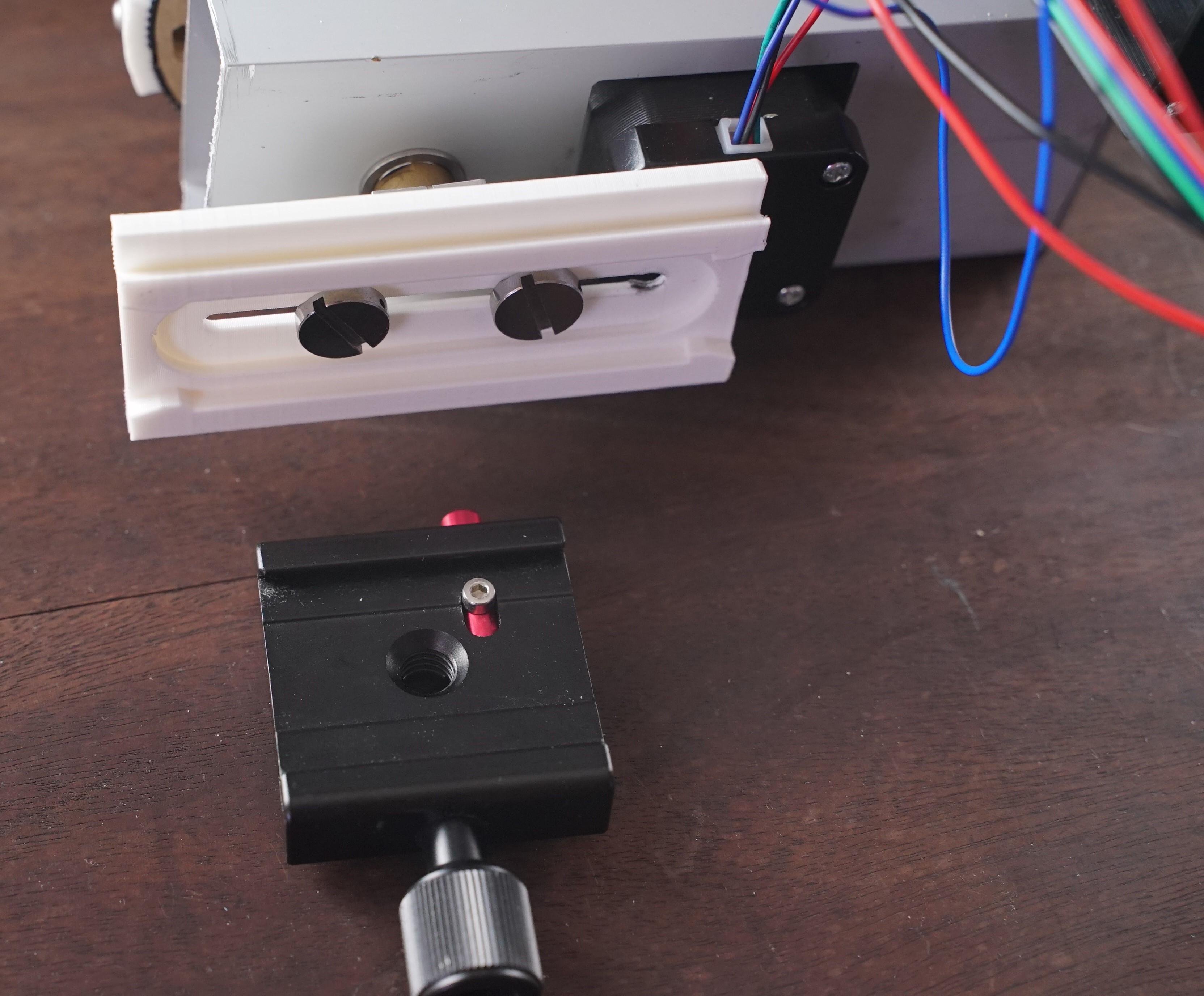
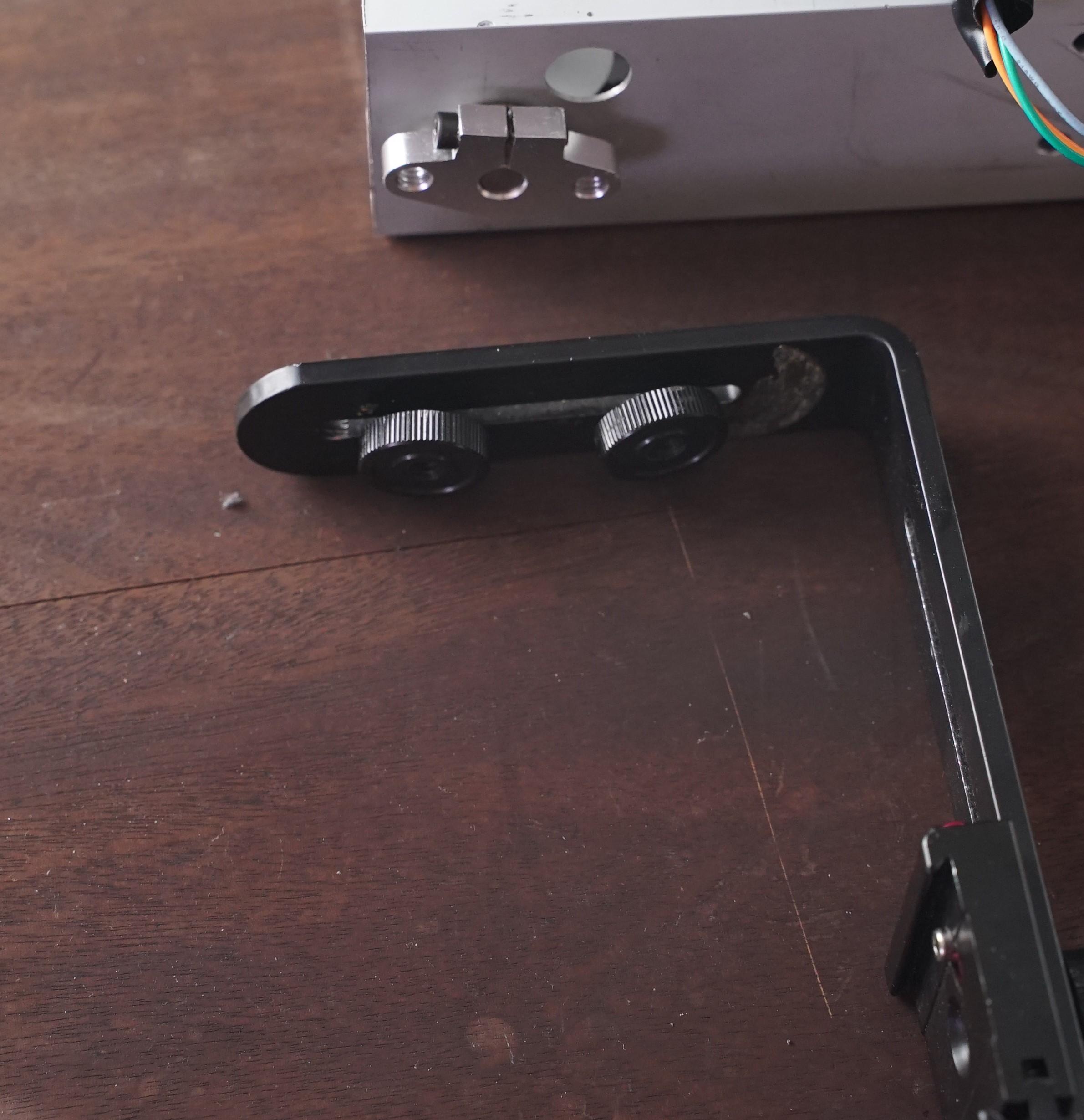
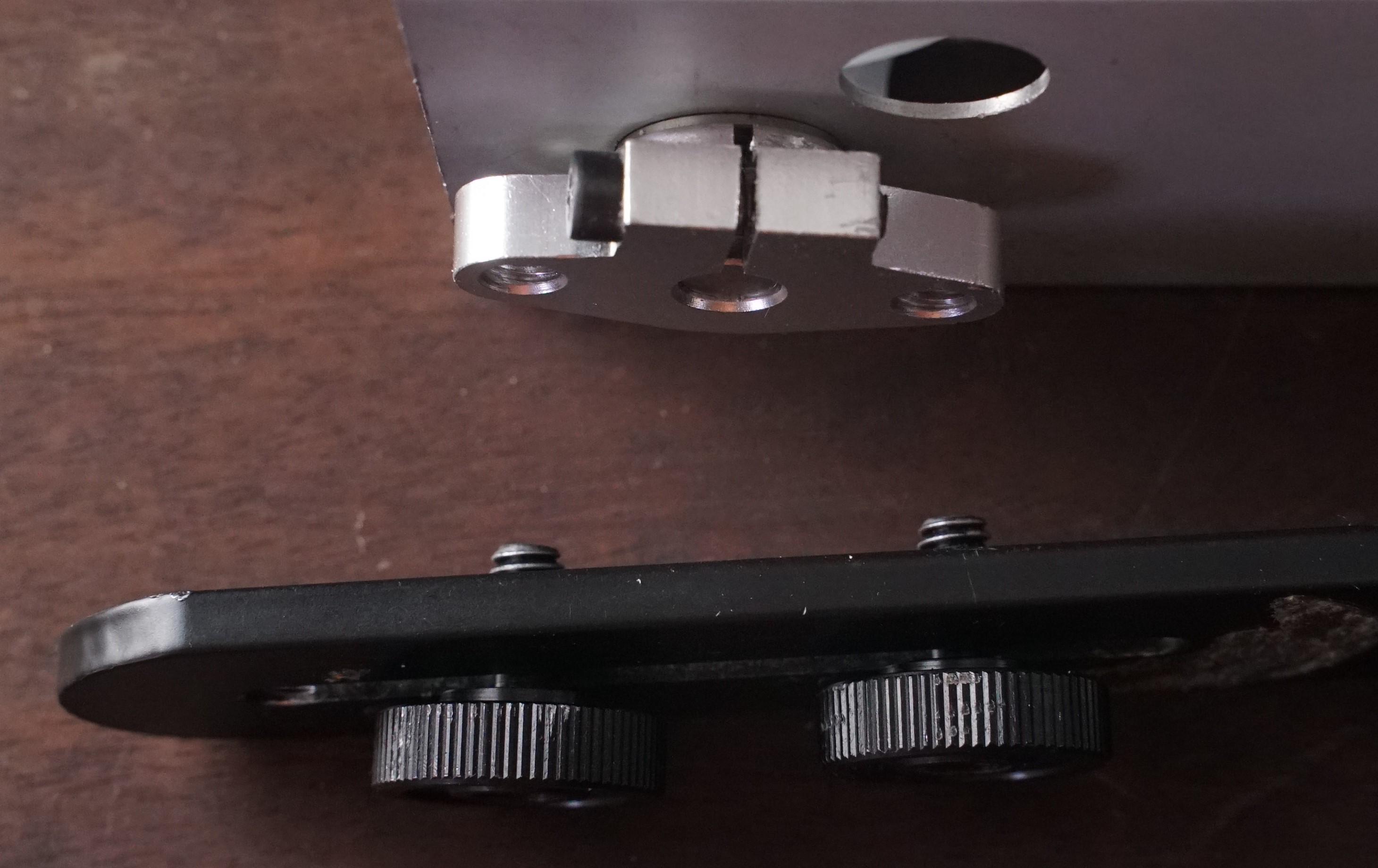
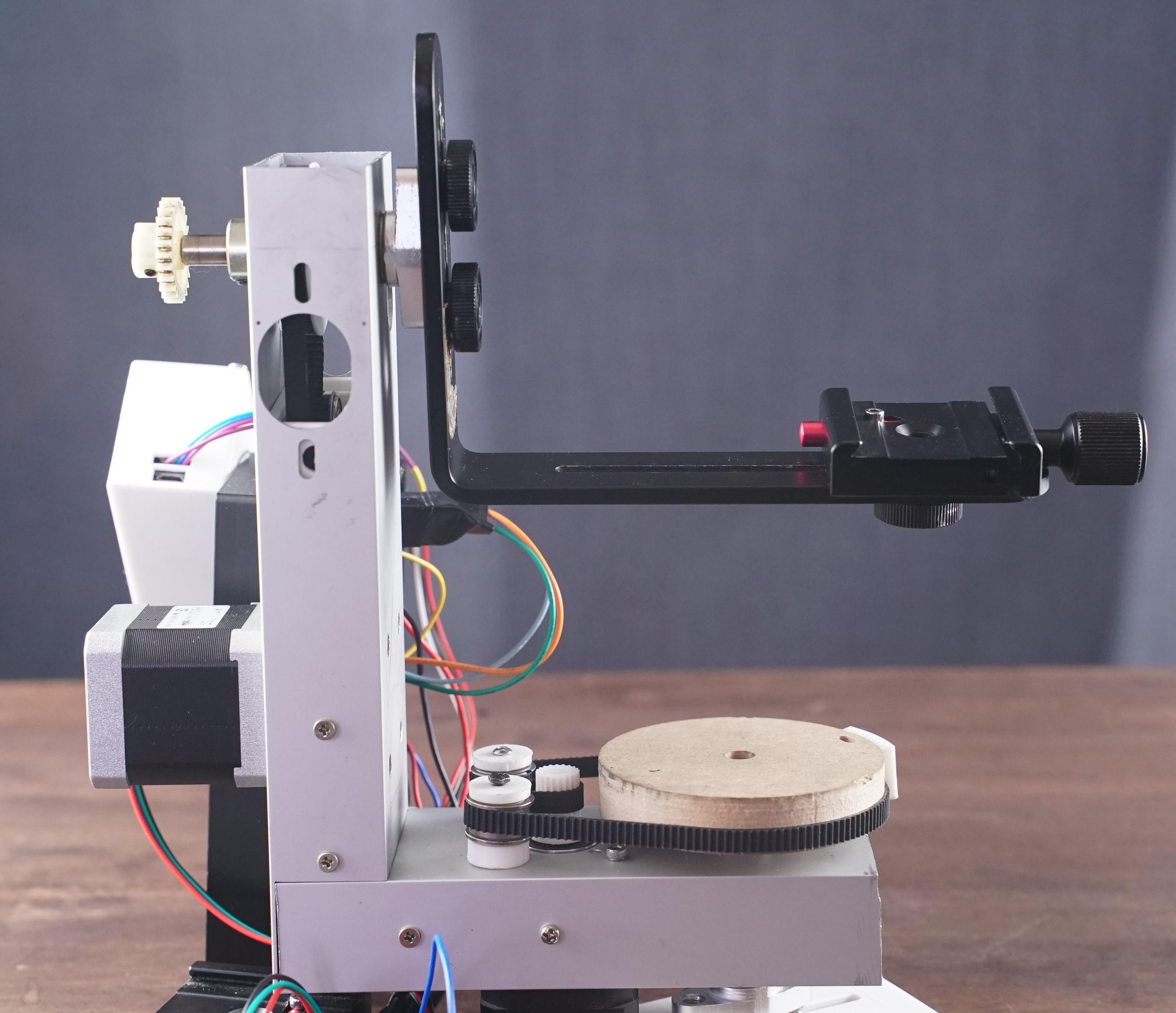
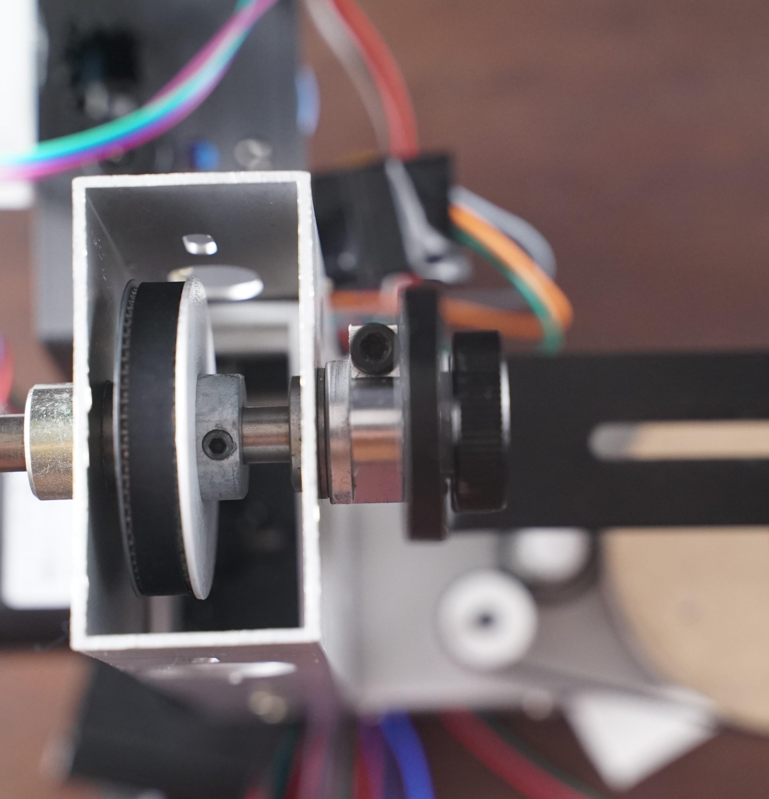
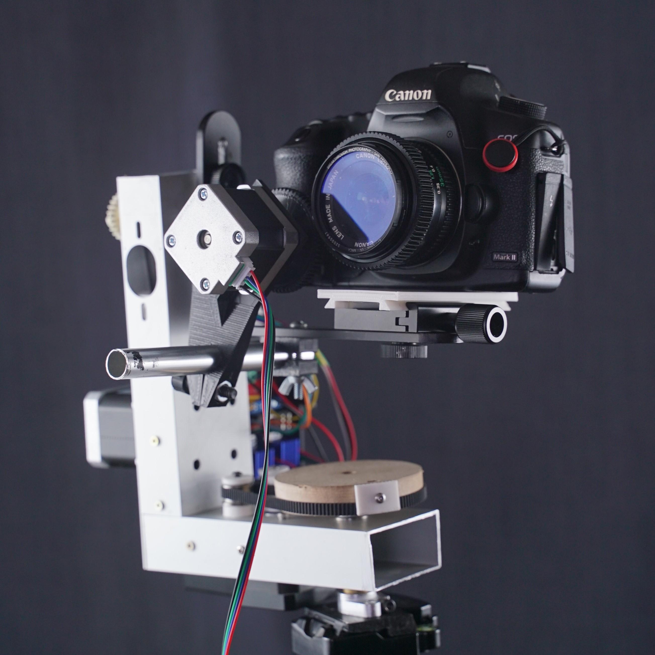
Use the 3d printer parts to assemble the pan tilt head.
You will need at least 4 aluminum extrusions, 32 v-slot M8 nuts and bolts, and right angle plates.
Assemble the parts following the fusion 360 generated pictures above and then mount the bearings for the axis and the motors using 2 flat mounting plates.
You can use 2 mounting plates over a nema 17 motor to secure the motor to the v-slot extrusions. You will need 4 M3x6 screws per motor. and 8 M3 or M4x15 screws to secure the bearings
You will need a set of gt2 pulleys and close loop belts, secure the pulleys to the 8mm rod and put the belt, before tighten the screws of the motor plates you can adjust the position of the motors to tighten the belts. Use an Allen key to secure the parts.
Cut the length of a 8mm steel rod for each axis and put the pieces together.
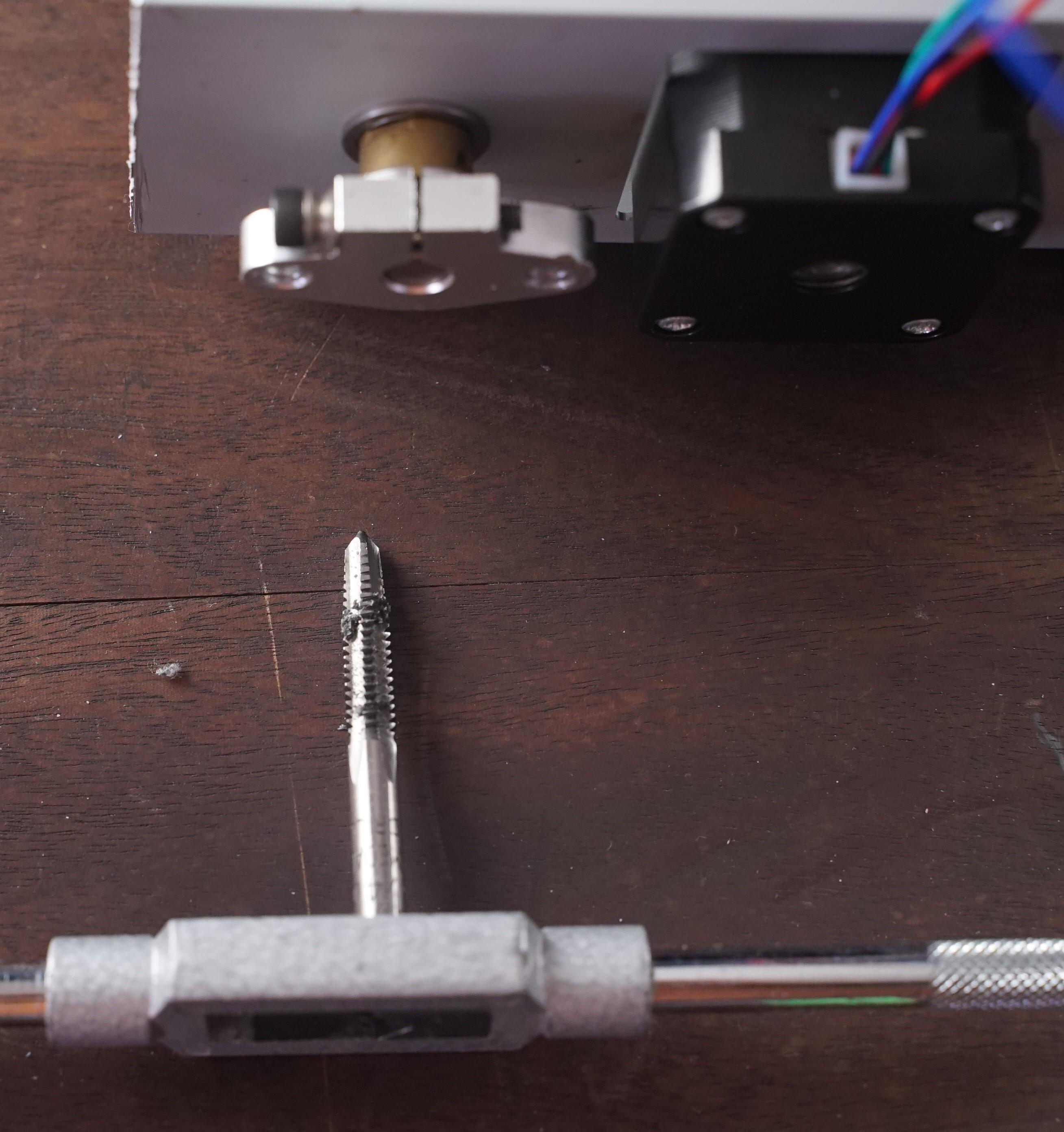
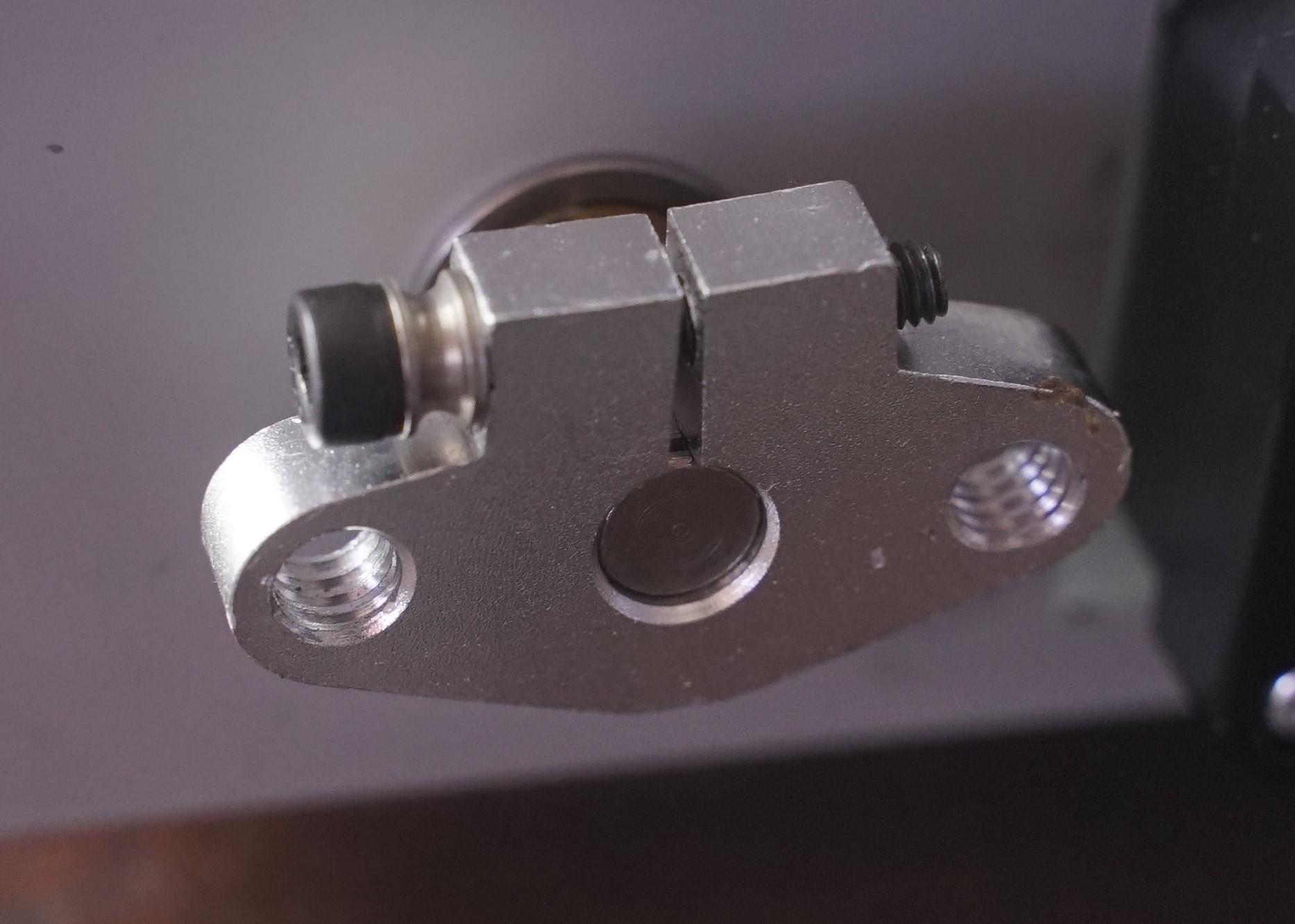
Tap the 8mm shaft vertical supports, the hole of these supports is the exact size to tap a 1/4-20 thread for camera screws.
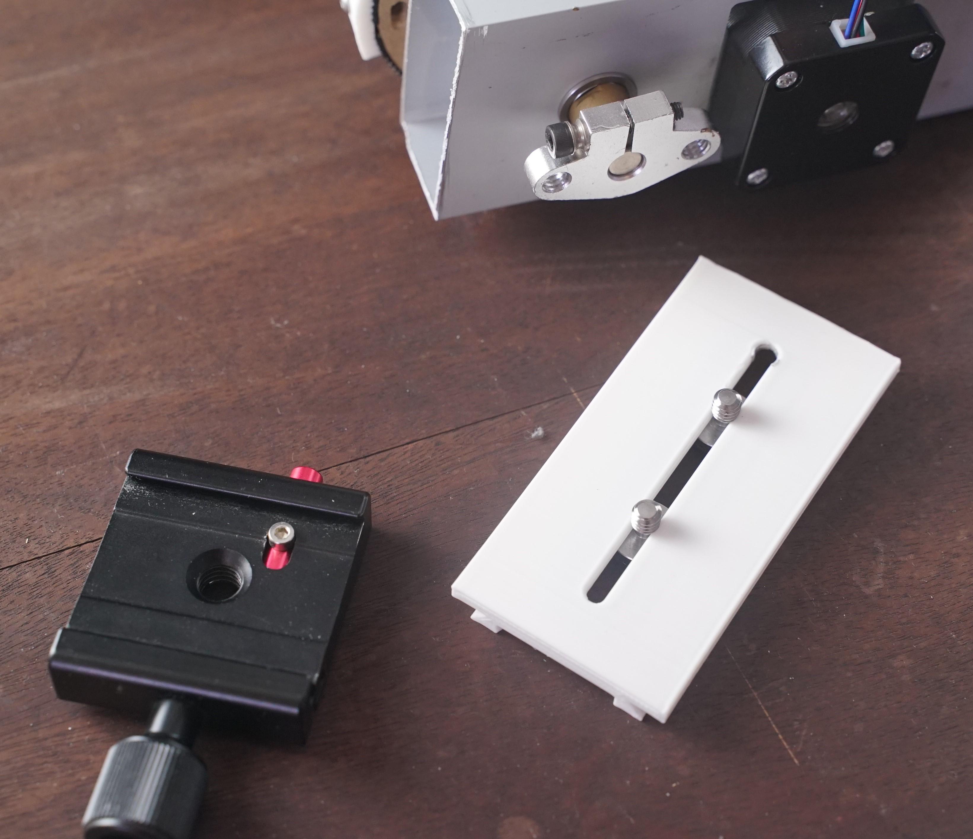
Attach the camera L bracket to the Y axis using 2 1/4 camera screws this way you can adjust the height of the camera to balance the weight.
Attach the long quick release plate to the L bracket to adjust the front rear position of the camera to balance the weight.
Attach the hole pan tilt head assembly to the second quick release plate with 2 1/4 screws and attach it to your tripod or slider.
Changing the 3d Printer Board Firmware
You need to change some configurations of your board in order to use the board and motors as a robot.
I have a ramps board with an arduino mega 2560 so I will leave the files for this combination, if you have a creality board or a BTT board you can check the last step where all the configuration mods you need to make, then compile the files using plataform.io and load the firmware using the SD card, I used arduino to load the firmware to the arduino mega 2560.
Note: These files works with Marlin Version 1.1.X.
- Replace the files inside the Marlin Folder.
- Open marlin.ino file.
- Compile the files using arduino
- Load the code to the arduino mega2560.
Programming the Remote Controller
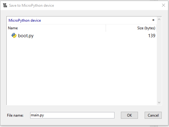
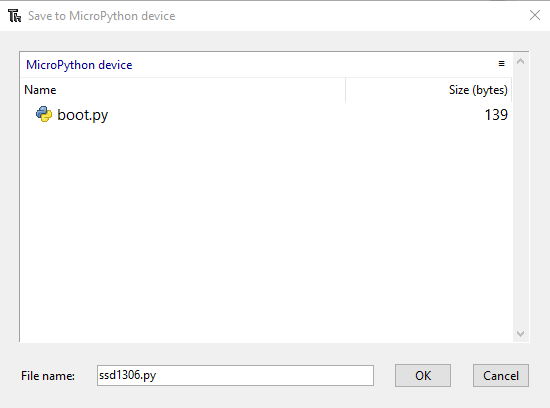
This is the most important part, why the 3d printer needs a controller? Because 3d printers read only a gcode file from a SD card, that's why we need to create a remote controller that sends the gcode lines instead of the SD card, this way we can control the 3d printer now a robot and control it with the phone app, this way will be the perfect camera operator.
To program the controller I used Thonny because is easy to program using this software, the code was done using micropython, you can learn micropython easily and add more functions to this code. Leave a comment below if you need a new function you can't find here.
To program the ESP32 you will need download the micropython version first: firmware link
Then load micropython to the board using Thonny.
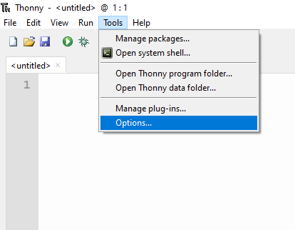
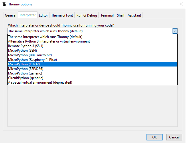
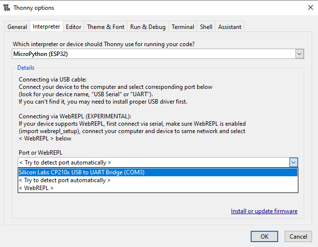
- Select the interpreter in Tools -> Options.
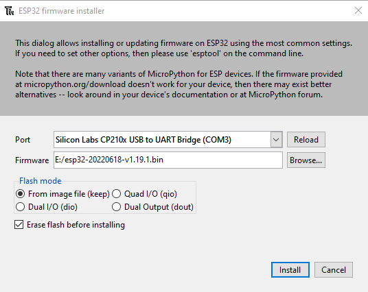
- Select the board you just connected and click on install or update software.
- Select the device COM PORT and the bin file from the link above and click on install. Wait until the installers complete.
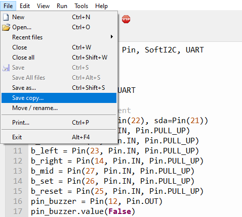
- Open the remote_controller.py file and click on File-> Save copy.
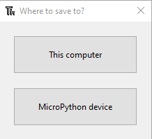
- Select Micropython device
- Save this file as main.py, because will be the main program in the ESP32.
- Repeat the save process with the ssd1306.py file, but keep the same name for this file as is the library that the main.py requires.
Then you are done programming the remote controller, now you can assembly it.
Assemble the Remote Controller
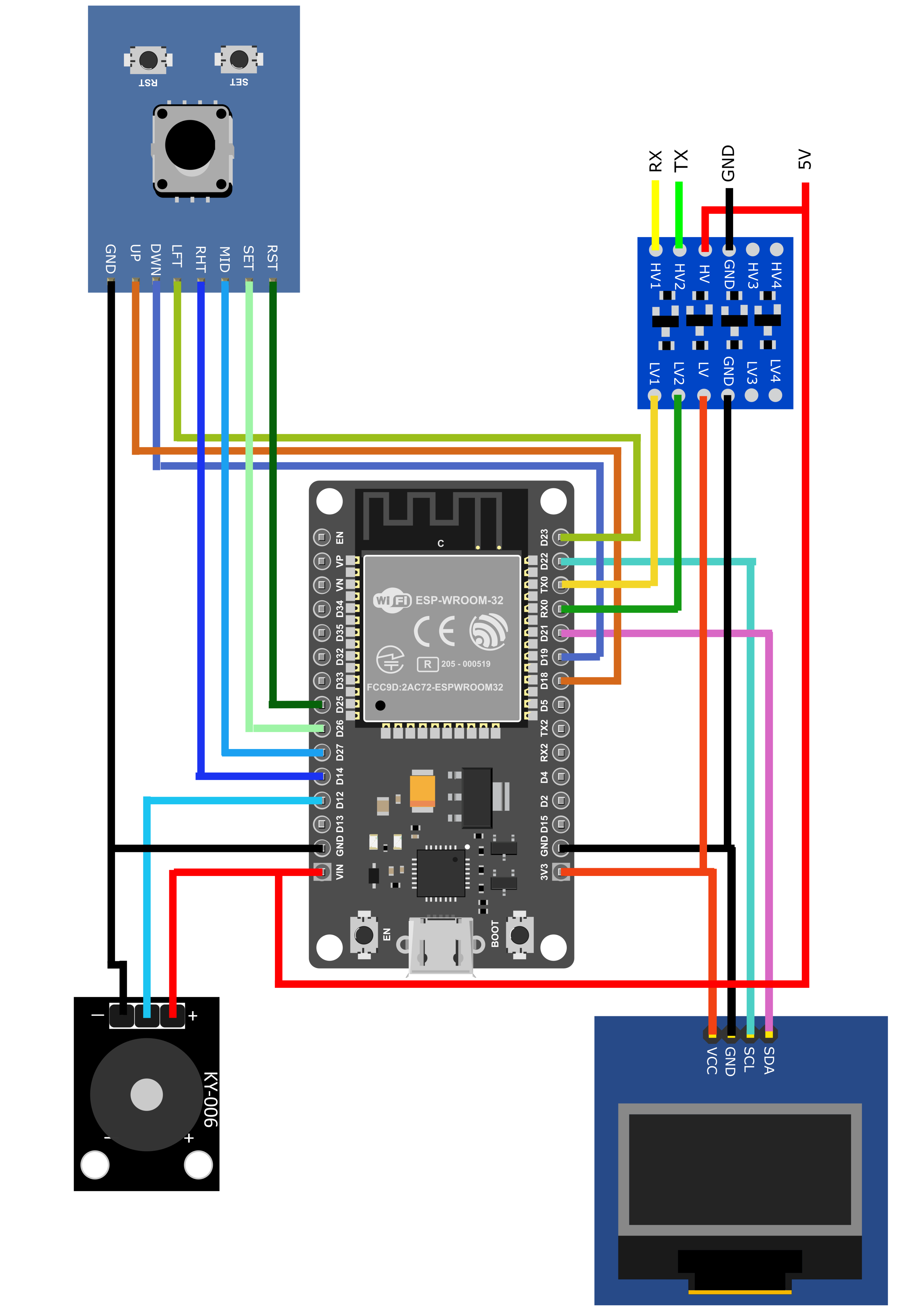
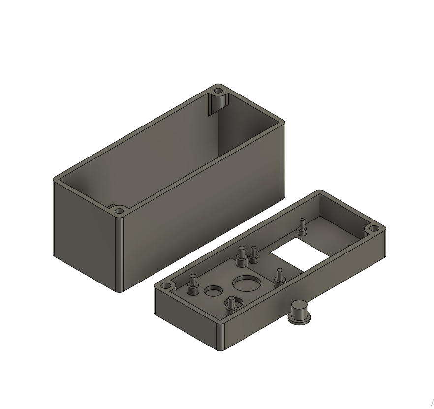
Follow the image to connect all the necessary pins of the remote controller. The ESP32 board works with 3V and my RAMPS board works with 5V so I need to connect a voltage logic adapter board between them. If you are using another controller board like a BTT SKR Mini you do not need the voltage logic adapter board. You can find the STL files for the remote controller Box.
Almost all 3d printer boards have a Secondary Serial Port the controller goes connected to this second serial port. For the RAMPS board is in the low part named SS Aux (VCC(+) GND(-) S S) This is where we connect the four cable of the remote controller and with the custom firmware from above we will be able to control our 3d printer board (now pan tilt head) with the remote controller.
Using the Remote Controller
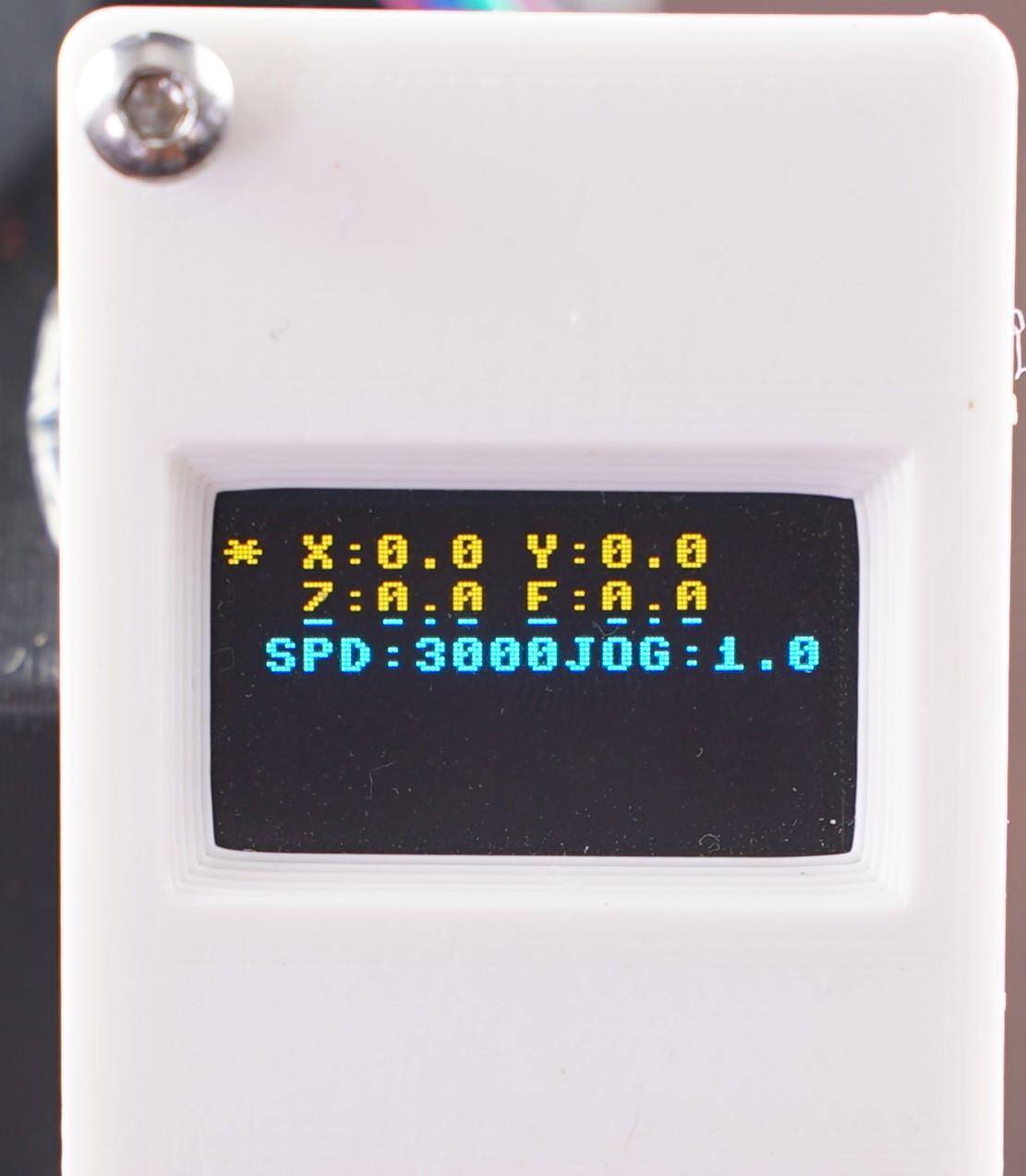
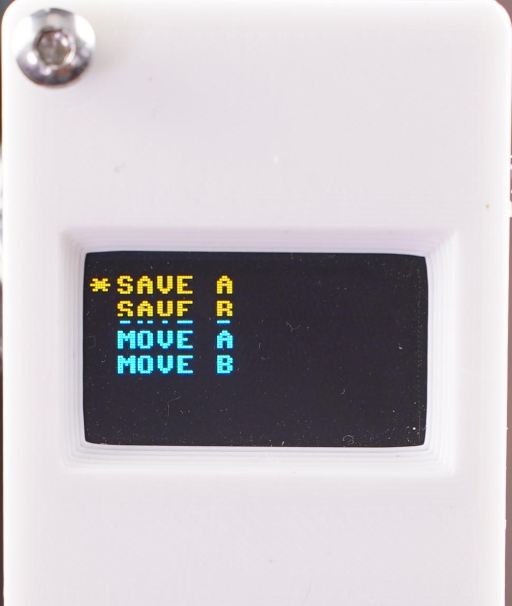
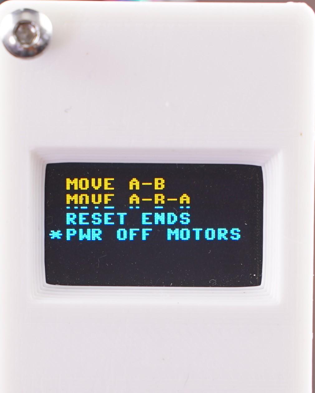
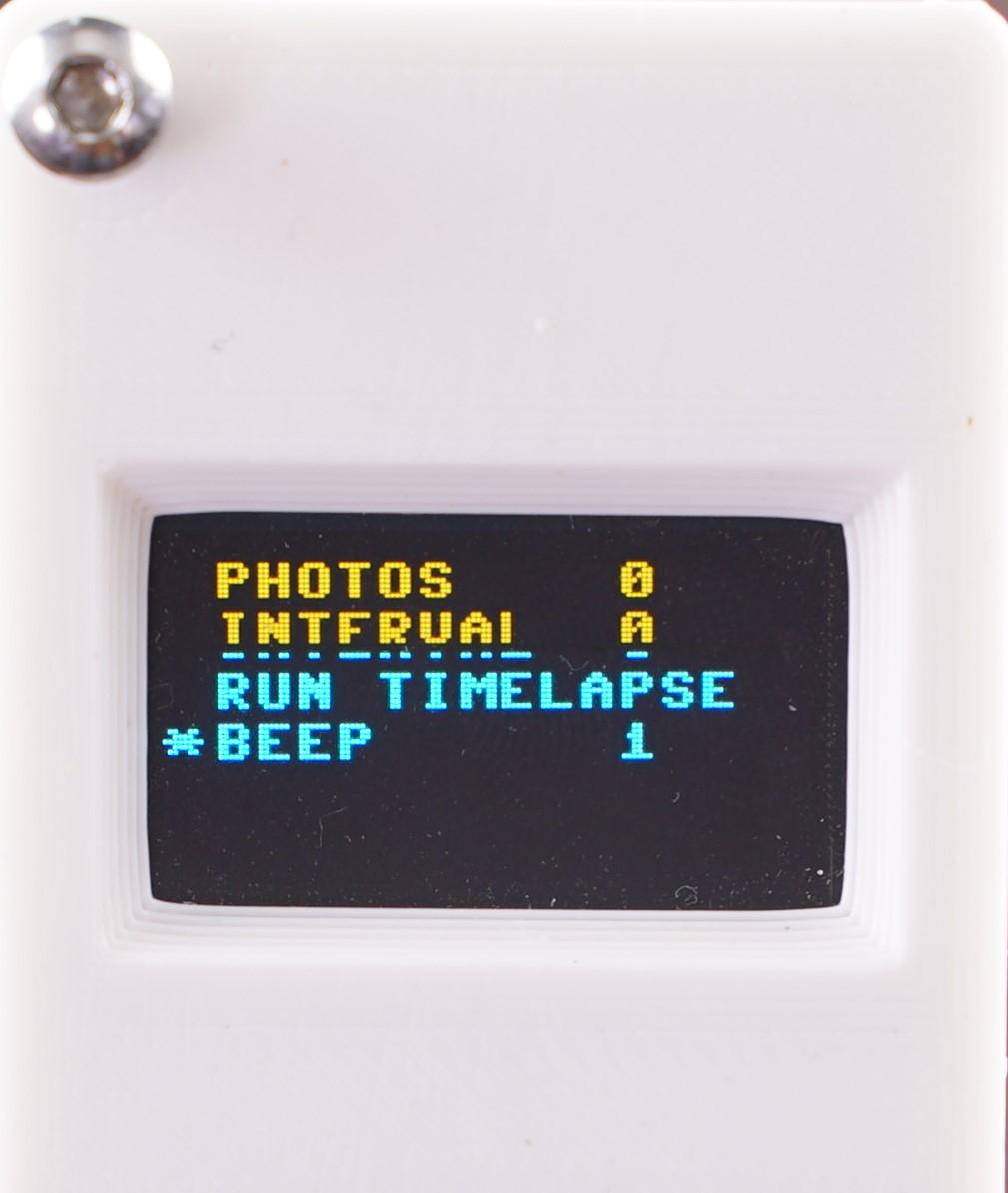
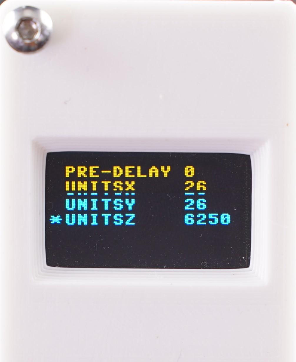
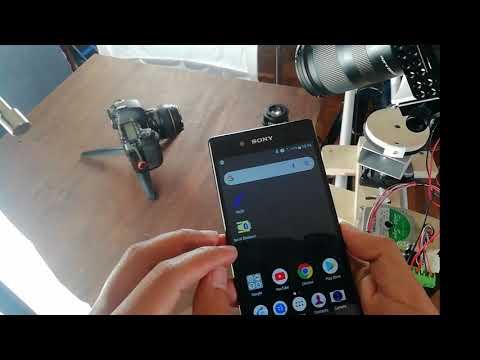
- Press the center button to change the joystick between the axis and the speed/jog controls.
- Use the joystick to move the pan, tilt, slide, focus axis.
- Press the right button to enter the menu.
- Press the left button to exit the menu.
Inside the Menu you can:
- Use the Joystick to navigate up and down.
- Activate each function pressing the middle joystick button.
- Save two positions A and B.
- Move the head between these two positions, only move to A, only move to B, move to A then B, etc.
- You can configure the steps per unit to calibrate your 3d printer board, this is preconfigured in the files above but if you change the pulleys or you are using gearbox stepper motors you can configure these parameters from the remote controller.
- Beep gives you a beep sound before the head starts its movement. setting this to 0 removes the beep. This beep is helpful to sync multiple shots for product videography.
- Delay adds a initial delay to the movement this is in seconds, this is helpful to shot a scene by yourself and you don't have a camera operator.
Using the Bluetooth App
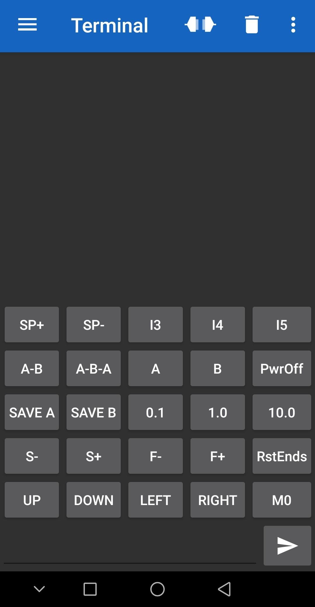
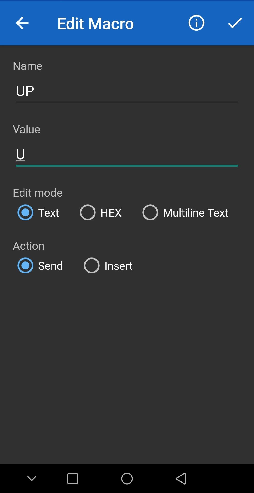
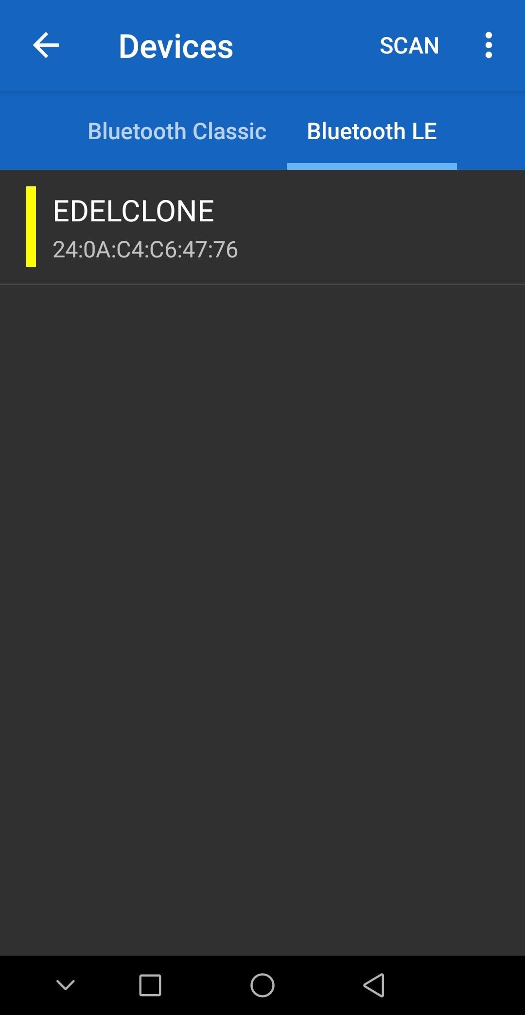
For remote controlling you will need to install the Serial Port Bluetooth App. The remote controller can communicate vie Bluetooth with this app and accepts certain messages to move and set the pan tilt head.
This is the list of messages:
U - moves the Tilt axis Up
D - moves the Tilt axis Down
R - moves the Pan axis Right
L - moves the Pan axis Left
SA - Saves the actual position as Position A
SB - Saves the actual position as Position B
A - Moves to Position A
B - Moves to Position B
AB - Moves first to Position A then Position B
ABA - Moves first to Position A then Position B then Position A again
1 - Set the jog movement to 0.1
10 - Set the jog movement to 1
100 - Set the jog movement to 10
RE - Reset Endstops, this is because 3d printers wait for a signal that it doesn't exists anymore if nothing moves at all this may be the reason
MO - Power off Motors if you are not using the head
ZP - Moves the Slider Left
ZM - Moves the Slider Right
FP - Moves the 4 axis or Focus motor Right
FM - Moves the 4 axis or Focus motor Left
SP - Increase the Speed by 100
SM - Decrease the Speed by 100
You can also configure presets in the app, that way you only press a button and don't write the message every time you wanna move the head.
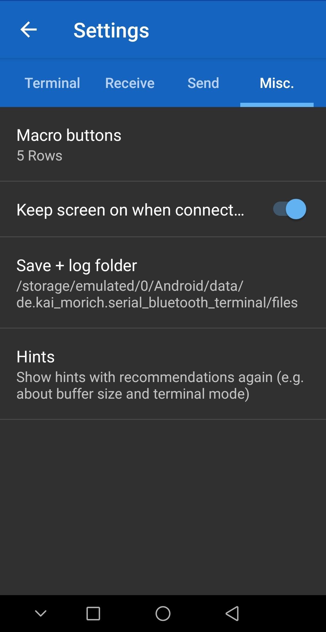
- To have more buttons in the app go to Settings -> Misc. and Select 5 Rows of buttons.
- Configure each button by long pressing and Select the Name and the correct Message to send from the list above.
- the Save the preset button.
- Last Sync the Bluetooth device, go to devices and press SCAN then find the ESP32 or EDELCLONE device and Pair.
- Once connected you can connect and disconnect clicking into the ports icon next to the Trash Icon on the top right.
And just have fun and make great videos!, the time-lapse feature is not tested yet, it will be included in the next video tutorial. Consider to subscribe in the YouTube Channel below.
Example Video, and Video Tutorial!
In this video I show you a example of the use of this Pan Tilt Slider Remote Controller.
Customize Your 3d Printer Board
This is the list you need to change in the following files of the marlin firmware.
Configuration.h File Changes
Change to 250000 the baudrate
#define BAUDRATE 250000
Comment this line, this enable to move the 4 axis without problems
//#define PREVENT_COLD_EXTRUSION
Change this line to 0
#define EXTRUDE_MINTEMP 0
Enable this lines
#define ENDSTOPPULLUP_XMIN
#define ENDSTOPPULLUP_YMIN
#define ENDSTOPPULLUP_ZMIN
change to true this lines because of the logic
#define X_MIN_ENDSTOP_INVERTING true // set to true to invert the logic of the endstop.
#define Y_MIN_ENDSTOP_INVERTING true // set to true to invert the logic of the endstop.
#define Z_MIN_ENDSTOP_INVERTING true
Change this lines according the steps per unit, the set of pulleys will be aprox. 27 so I round it to 30 and we reduce the acceleration to the minimum to have smooth movements.
#define DEFAULT_AXIS_STEPS_PER_UNIT  { 30, 30, 30, 30 }
#define DEFAULT_MAX_FEEDRATE     { 6000, 6000, 6000, 6000 }
#define DEFAULT_MAX_ACCELERATION   { 1, 1, 1, 1 }
#define DEFAULT_ACCELERATION     1000  // X, Y, Z and E acceleration for printing moves
#define DEFAULT_RETRACT_ACCELERATION 1000  // E acceleration for retracts
#define DEFAULT_TRAVEL_ACCELERATION  1000  // X, Y, Z acceleration for travel (non printing) moves

#define DEFAULT_XJERK         0.3
#define DEFAULT_YJERK         0.3
#define DEFAULT_ZJERK         0.3
#define DEFAULT_EJERK         0.3
this is really important because it limits the movement on the negative axis, I set it up to 600 to have a big range of movement.
#define X_MIN_POS -600
#define Y_MIN_POS -600
#define Z_MIN_POS -600
enable this, this enable to change the parameters using the remote controller.
#define EEPROM_SETTINGS
Change this parameters to enable free movement without any alarm.
#define Z_SAFE_HOMING
and this
#define MANUAL_X_HOME_POS 0
#define MANUAL_Y_HOME_POS 0
#define MANUAL_Z_HOME_POS 0
otherwise the position when the controller is turned on will be -200 and that will not let us move in one direction
Condiguration_adv.h File changes
enable this
#define USE_CONTROLLER_FAN
change the pin to a unused one, we change this because we will use the fan pins to control the shutter in the future, for timelapse functions.
#define CONTROLLER_FAN_PIN 57
set all to false to avoid the motors to turn off automatically
#define DISABLE_INACTIVE_X false
#define DISABLE_INACTIVE_Y false
#define DISABLE_INACTIVE_Z false
#define DISABLE_INACTIVE_E false
set the minimum steps per movement to 1, this will allow to move small movements like 0.1 degrees.
#define MIN_STEPS_PER_SEGMENT 1
Some extra changes on the SKR MINI E3 V2.0
we change the heater pin to A8 that is used for neopixel (unused)
in the File: \BIGTREETECH-SKR-mini-E3-master\firmware\V2.0\Marlin-2.0.8.2.x-SKR-mini-E3-V2.0\Marlin\src\pins\stm32f1\pins_BTT_SKR_MINI_E3_common.h
#define HEATER_0_PIN PA8
also I changed the Neopixel pin to avoid problems
in the File: \BIGTREETECH-SKR-mini-E3-master\firmware\V2.0\Marlin-2.0.8.2.x-SKR-mini-E3-V2.0\Marlin\src\pins\stm32f1\pins_BTT_SKR_MINI_E3_V2_0.h
#define NEOPIXEL_PIN -1
also we enable M42 and M43 in Configuration_adv.h
//
// M42 - Set pin states
//
#define DIRECT_PIN_CONTROL

//
// M43 - display pin status, toggle pins, watch pins, watch endstops & toggle LED, test servo probe
//
#define PINS_DEBUGGING
This will help us to control the non-protected pins
with M43 you can see the order of pins for this boards let say PC8 is P40, but also you can find it
in these files
\BIGTREETECH-SKR-mini-E3-master\firmware\V2.0\Marlin-2.0.8.2.x-SKR-mini-E3-V2.0\buildroot\share\PlatformIO\variants\MARLIN_F103Rx\variant.cpp
\BIGTREETECH-SKR-mini-E3-master\firmware\V2.0\Marlin-2.0.8.2.x-SKR-mini-E3-V2.0\buildroot\share\PlatformIO\variants\MARLIN_F103Rx\variant.h