True to Scale Landscape on Laser Cutter
by jschrempp in Workshop > CNC
6765 Views, 64 Favorites, 0 Comments
True to Scale Landscape on Laser Cutter
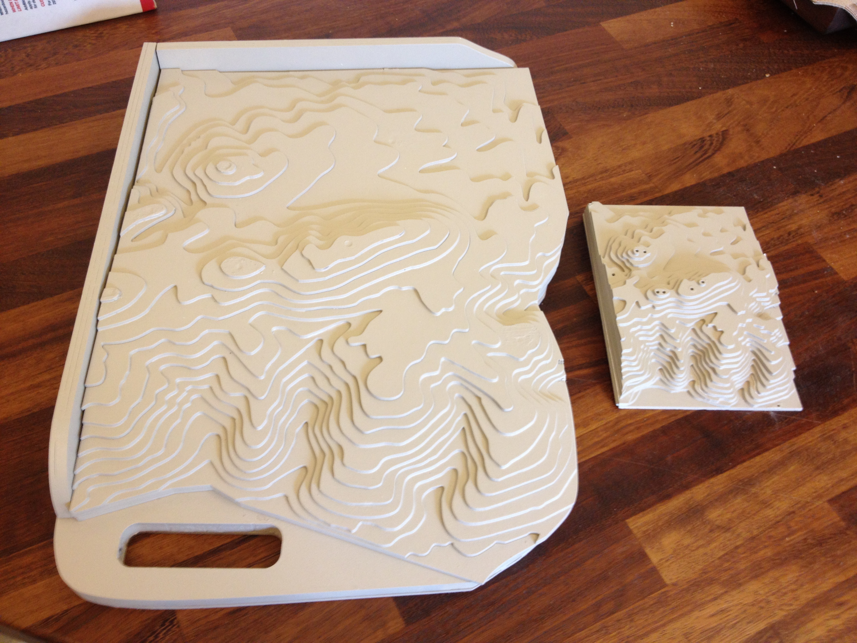
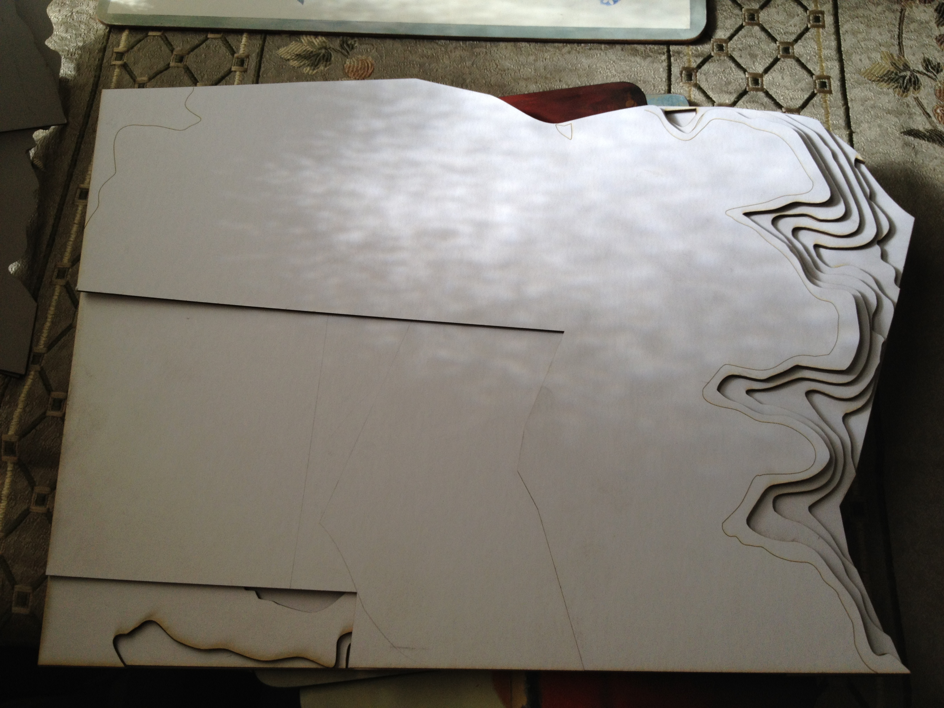
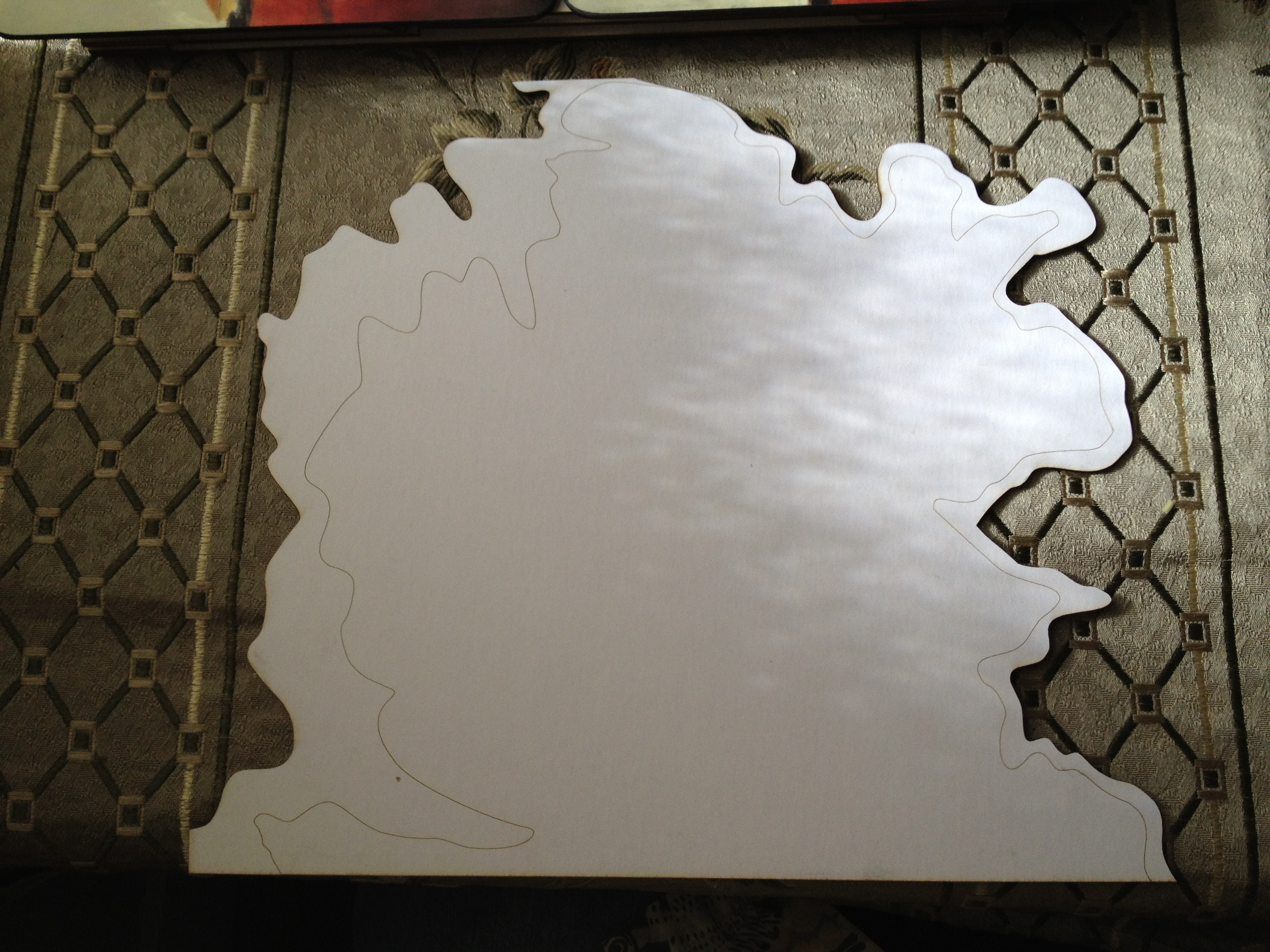
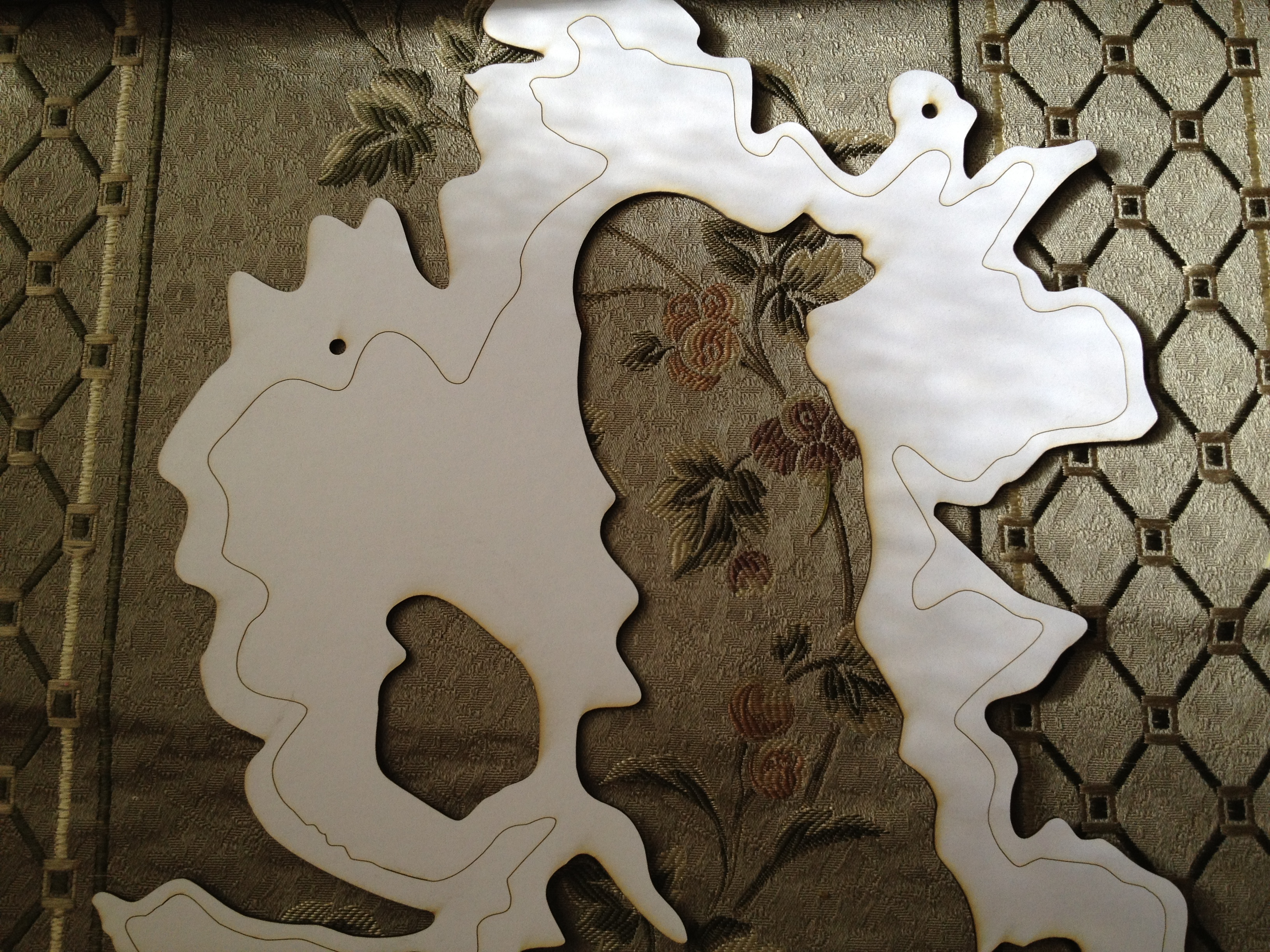
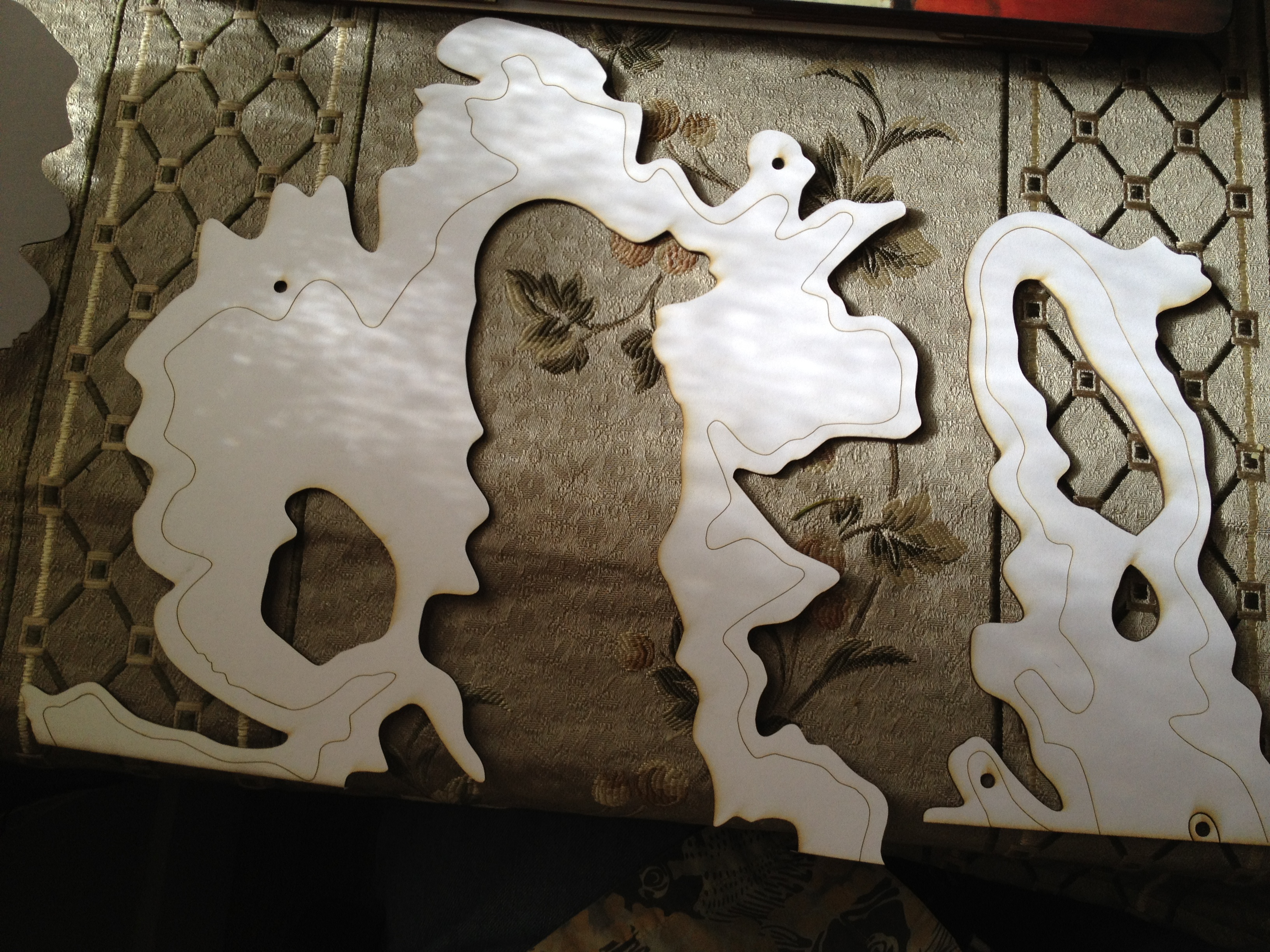
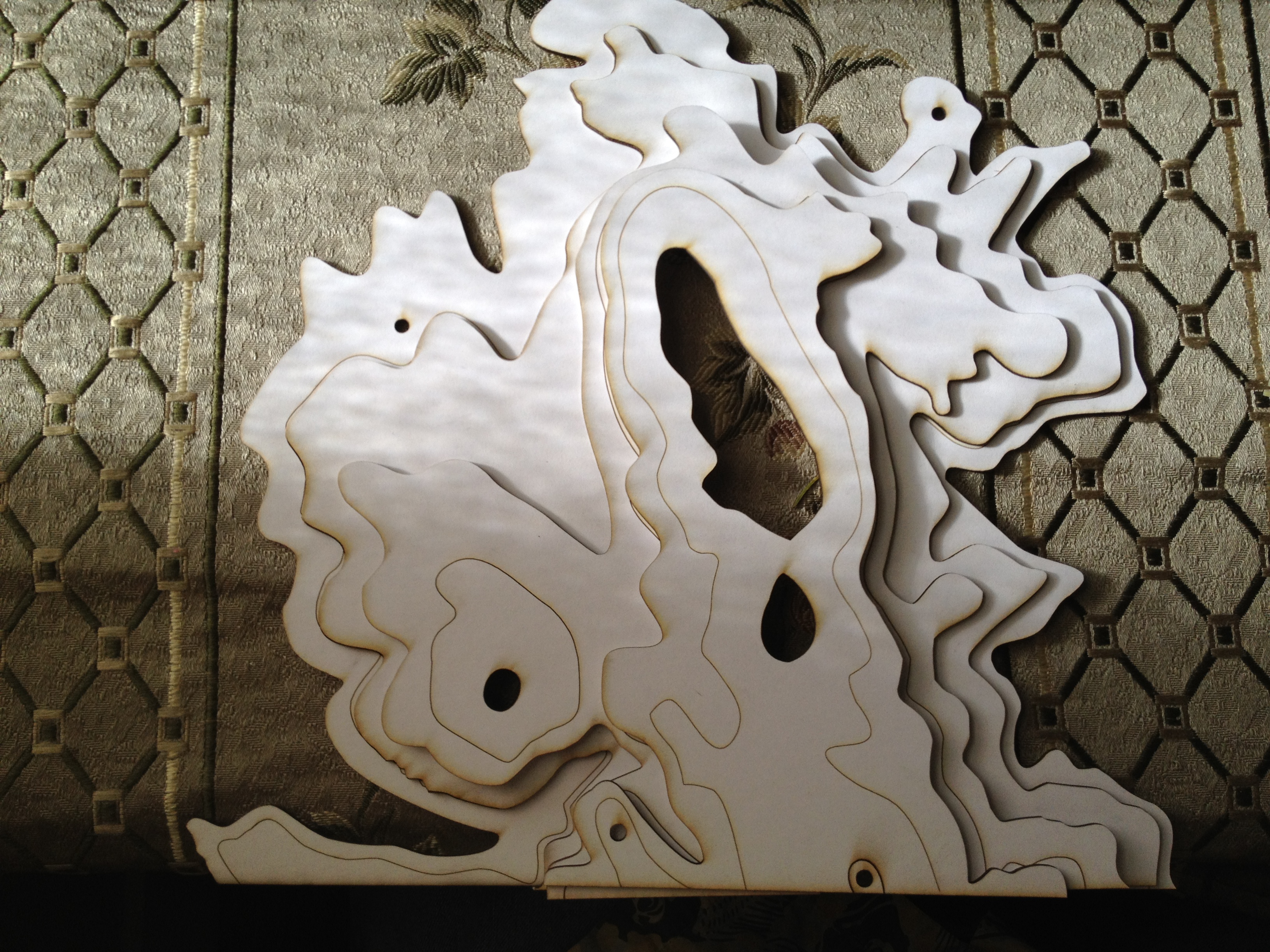
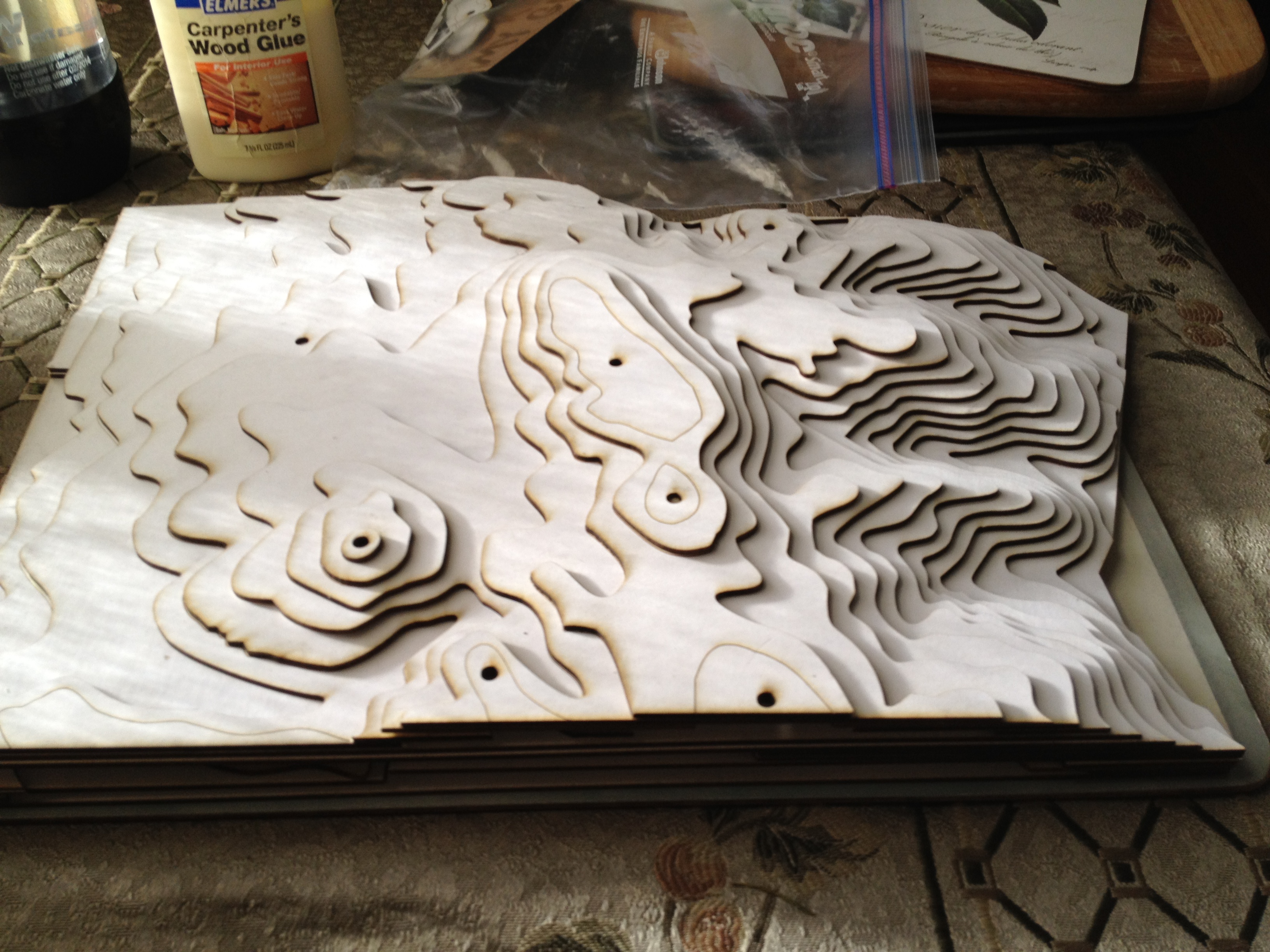
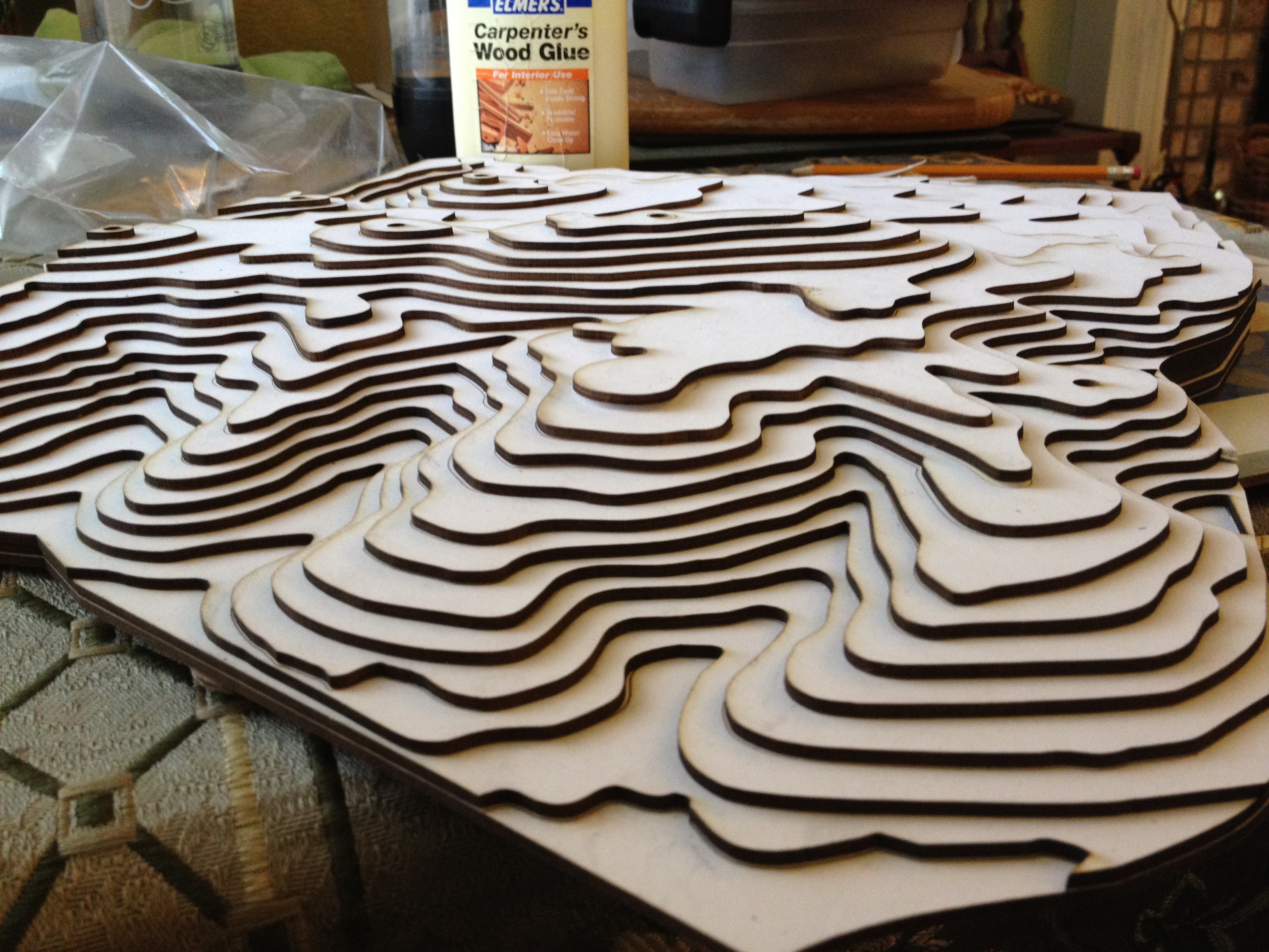
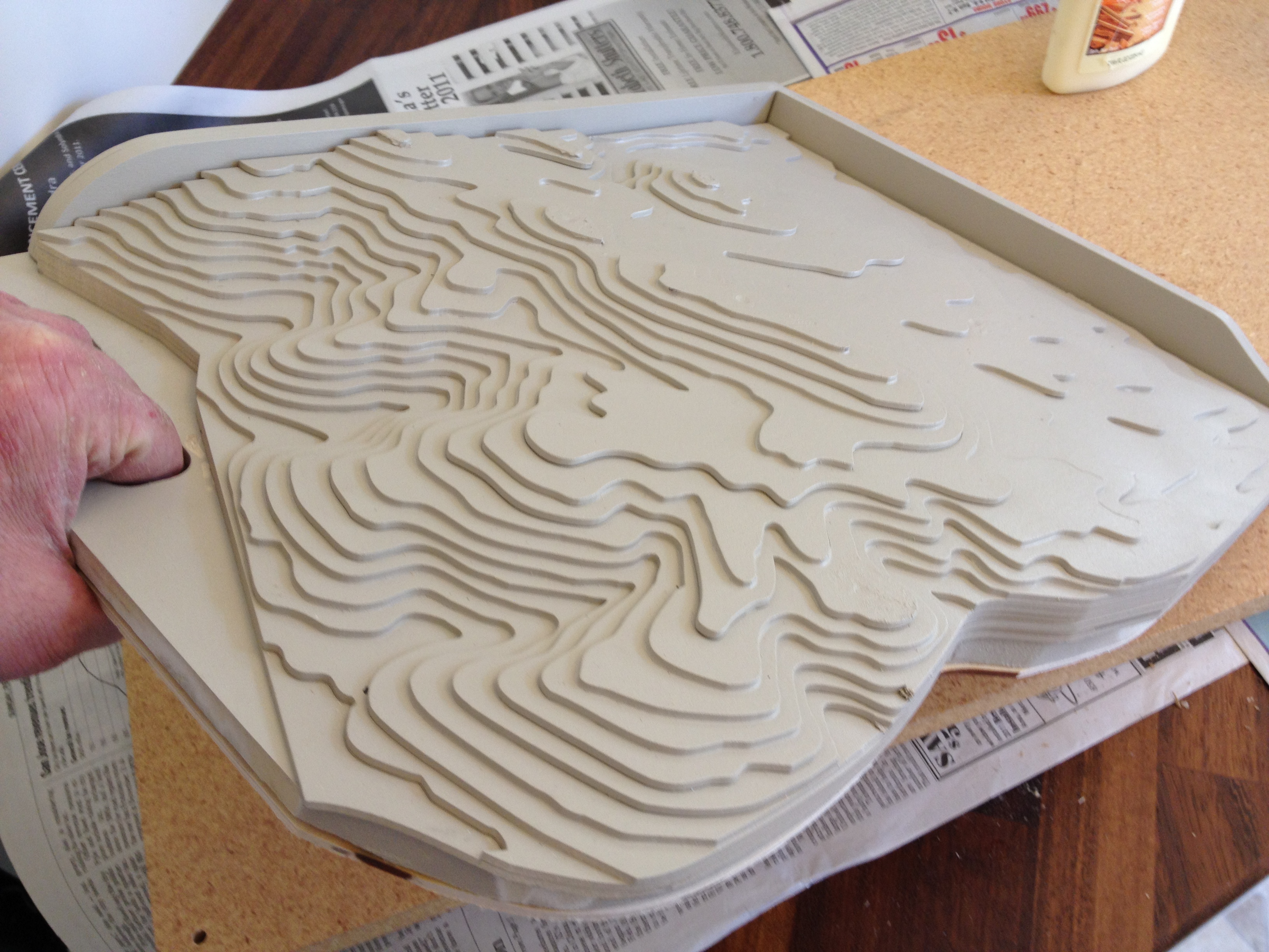
I hadn't planned to make a bigger model. But when my small model garnered some "where is that?" questions from my friends, I knew that another model was in my future. You see, the small pocket model of Edgewood park is good, but it isn't to horizontal scale. The hills are too high, the valleys too deep. My friends had a difficult time translating that to what they know of the park. Fair enough. True scale it will be! As it turned out, the larger size led me to make a lot of improvements to my process. I spent quite a few hours at TechShop Menlo Park. Not only with CorelDraw and the Epilog Helix laser cutter, but also the sander and paint booth. But I'm getting ahead of the story...
Figure Out the Scale
The first step is to figure out how big the final model needs to be. I used calipers to measure the thickness of the mat board I was using. I found it to be 1/8-inch thick.
Next, I needed to know how much vertical distance each contour line represents. On a topographic map some lines are thicker and labeled with feet above sea level. On the topo I used one line was labeled 400, another 600. Between them were four lines, which makes five segments of increasing altitude. (600-400) = 200 feet. 200 / 5 = 40 feet per contour. Your topo map may be different so do the math yourself.
So my scale would now be 1/8th-inch = 40 feet. Or multiply each side by 8 and you get 1 inch = 320 feet.
Using a ruler I measured one side of the park boundaries and found it to be 5.2 inches. The topo map legend said the scale was 1 inch = 1000 feet. So that one side of the park is 5200 feet long.
To determine how long that one side of my model should be I divided 5200 feet by 320 feet. (5200 / 320) = 16.25 inches.
Knowing that the one side of my model needs to by 16.25 inches long, I opened CorelDraw and selected all layers. I then pulled on one corner handle until the entire project grew to be 16.25 inches on the specified side. That's done, my project is now to scale.
Elevations to Layers
To make the next step easier I decided to move each elevation to a separate layer in CorelDraw. Since my landscape has several hills and valleys, one elevation might have several contour lines in it. I started by adding 20 empty layers to my drawing. I found that the top contour line in my model was for 840 feet. I selected the top most blank layer and renamed it to "840" and left it selected. Then I used the selection tool to pick the 840 foot contour. Control-x, Control-v and that contour line was now in the 840 layer! I set the visibility of that layer to hidden (the little eye icon should be closed) and the contour line disappeared from the screen.
I labeled the next drawing layer "820" and left it selected. Again using the selection tool I picked the contour line for 820 feet and cut / paste it into the 820 layer. In my particular landscape there is another hill with an 820 contour. I selected that contour and did another cut/paste. Set the layer visibility to hidden and, bingo, both lines disappear from the screen.
This is a bit of tedious work, but it will really come in handy when you start to cut the model. So just keep doing this until each elevation in your landscape is in its own CorelDraw layer.
Plan Your Cuts
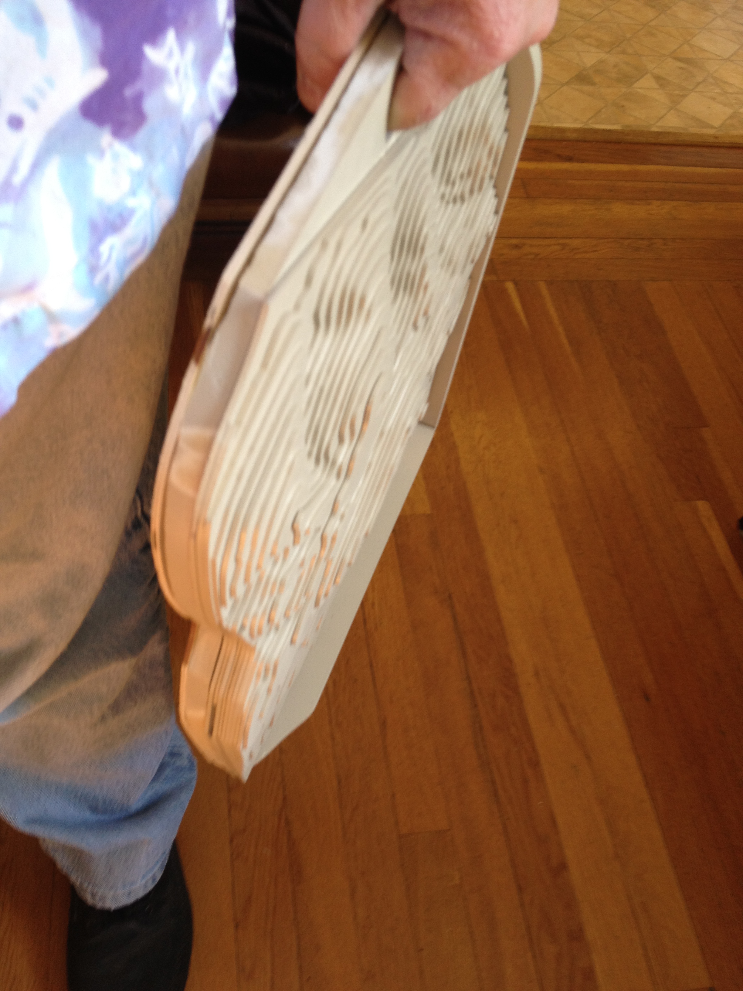
I cut the little 4x5 inch model from one sheet of mat board. When I started counting up this project I realized that I'd need closer to 10 sheets - ouch! That would put a dent in my pocketbook. And the resulting model would be heavy, limiting my ability to take it everywhere. I decided that this big model would have to be hollow.
Your job is now to figure out which parts can be cut from the middle of others. For instance, consider the contours at the base of a mountain. Certainly you could cut the little contour of the top of the mountain from the center of the base contour without doing any harm. But you might also be able to cut the contour from half way up the mountain out of that same base contour piece. This can save a lot of material.
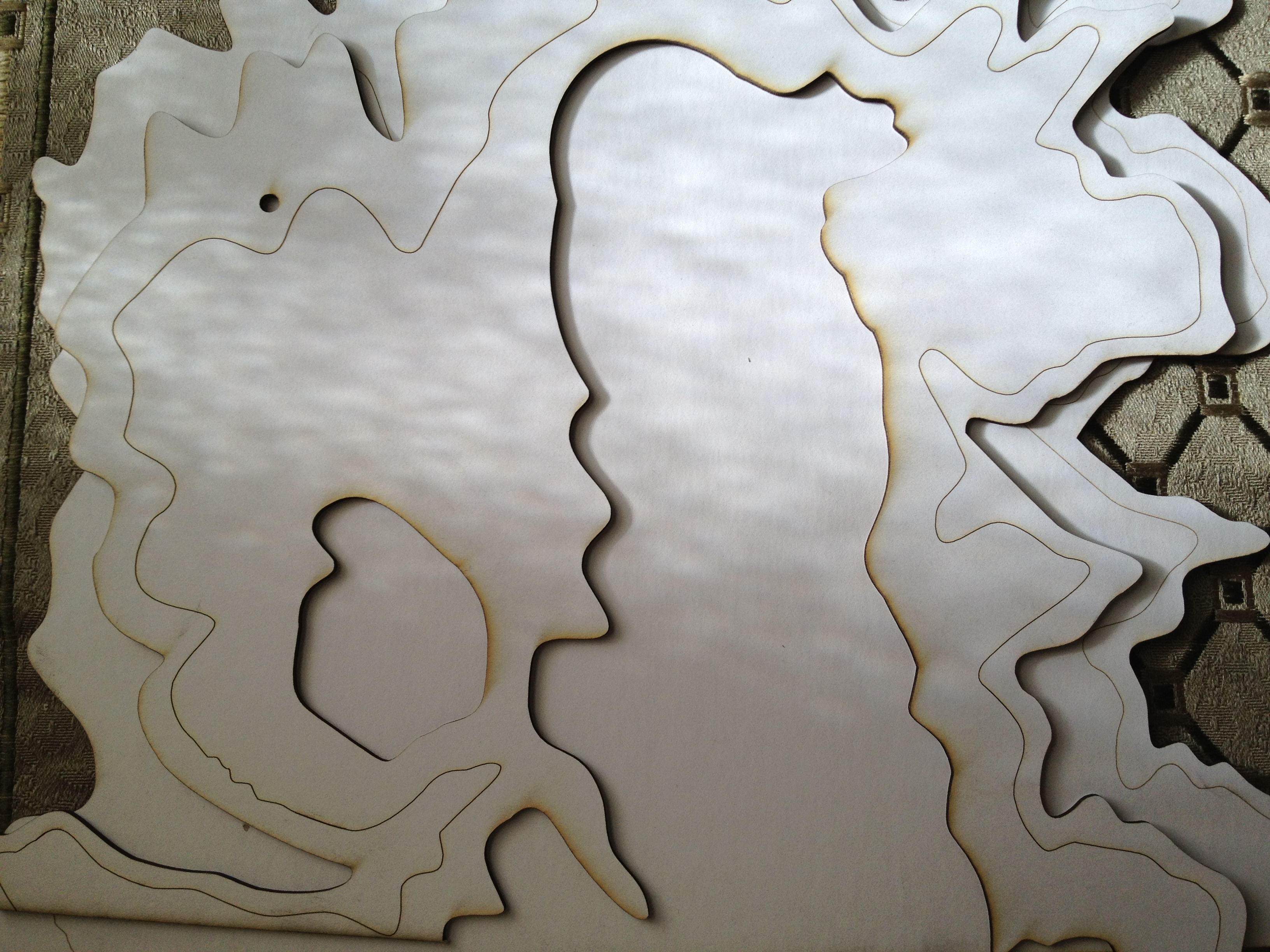
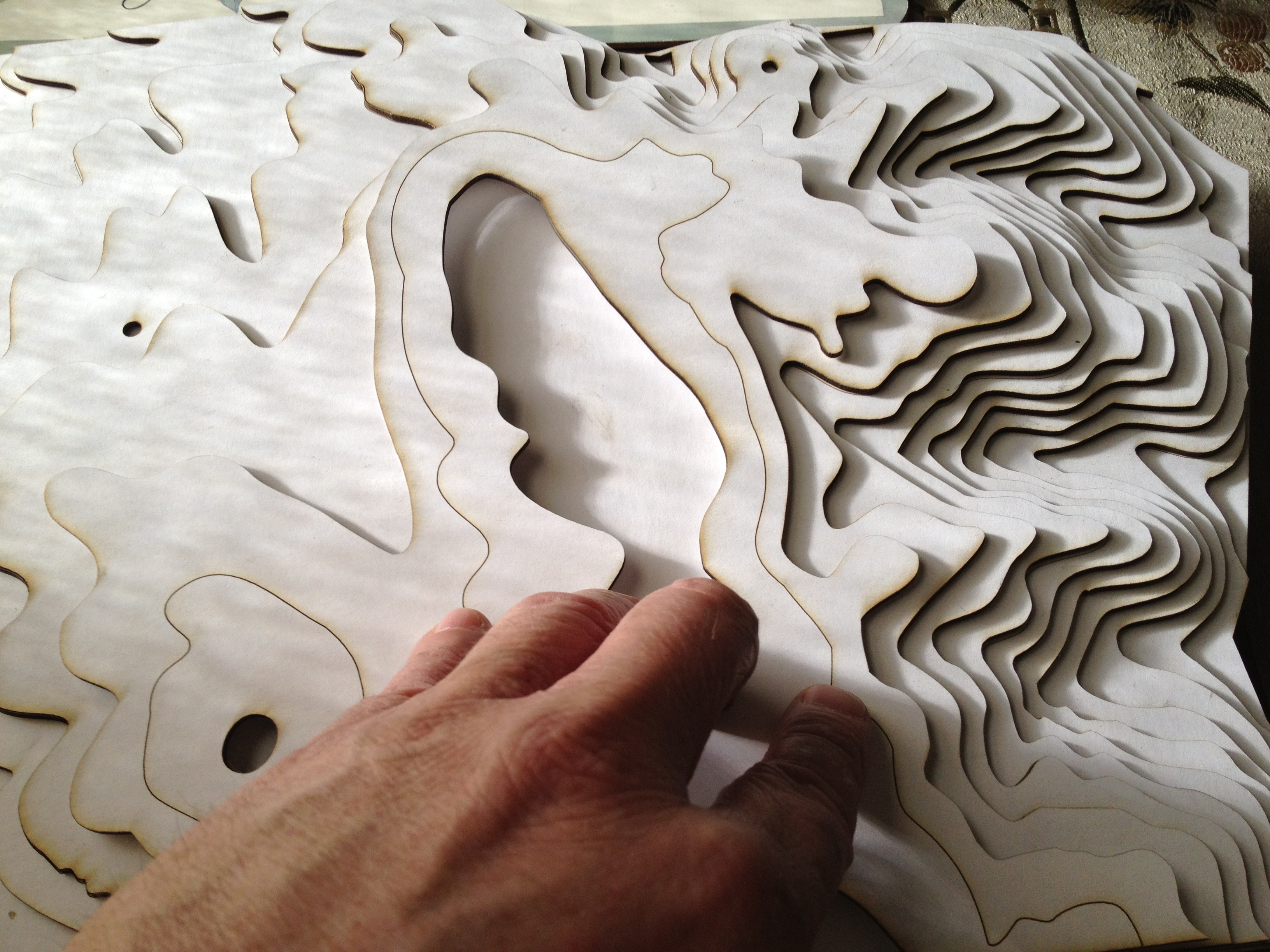
After some experimentation I found that in general I could skip three contour lines and cut again. To see the effect just un-hide the layers that you think you can cut from one sheet of mat board. You want to leave enough material so that other layers between these have enough overlap to let you glue them together solidly. You can see what I've done in some of the attached photos.
Alignment
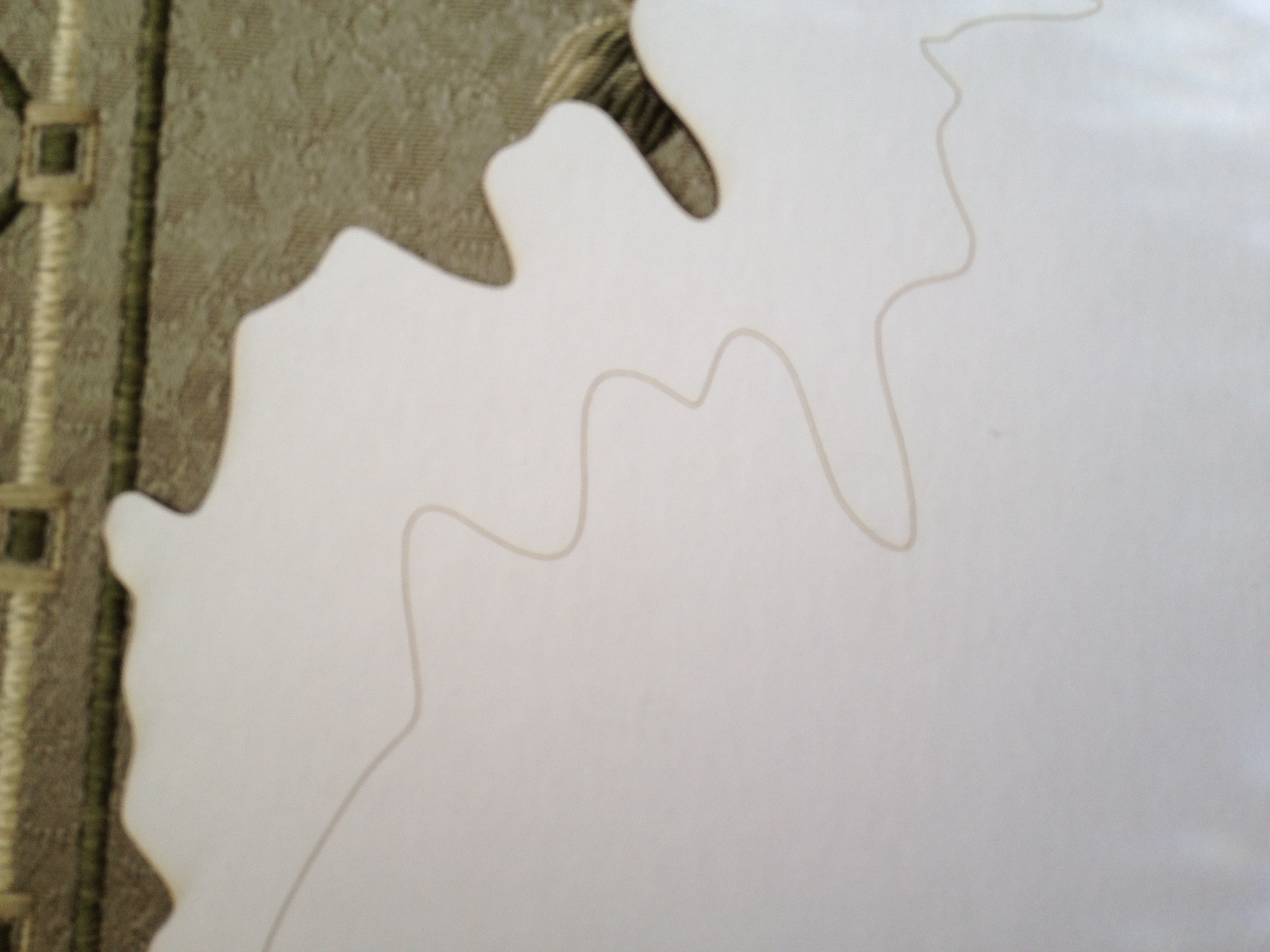
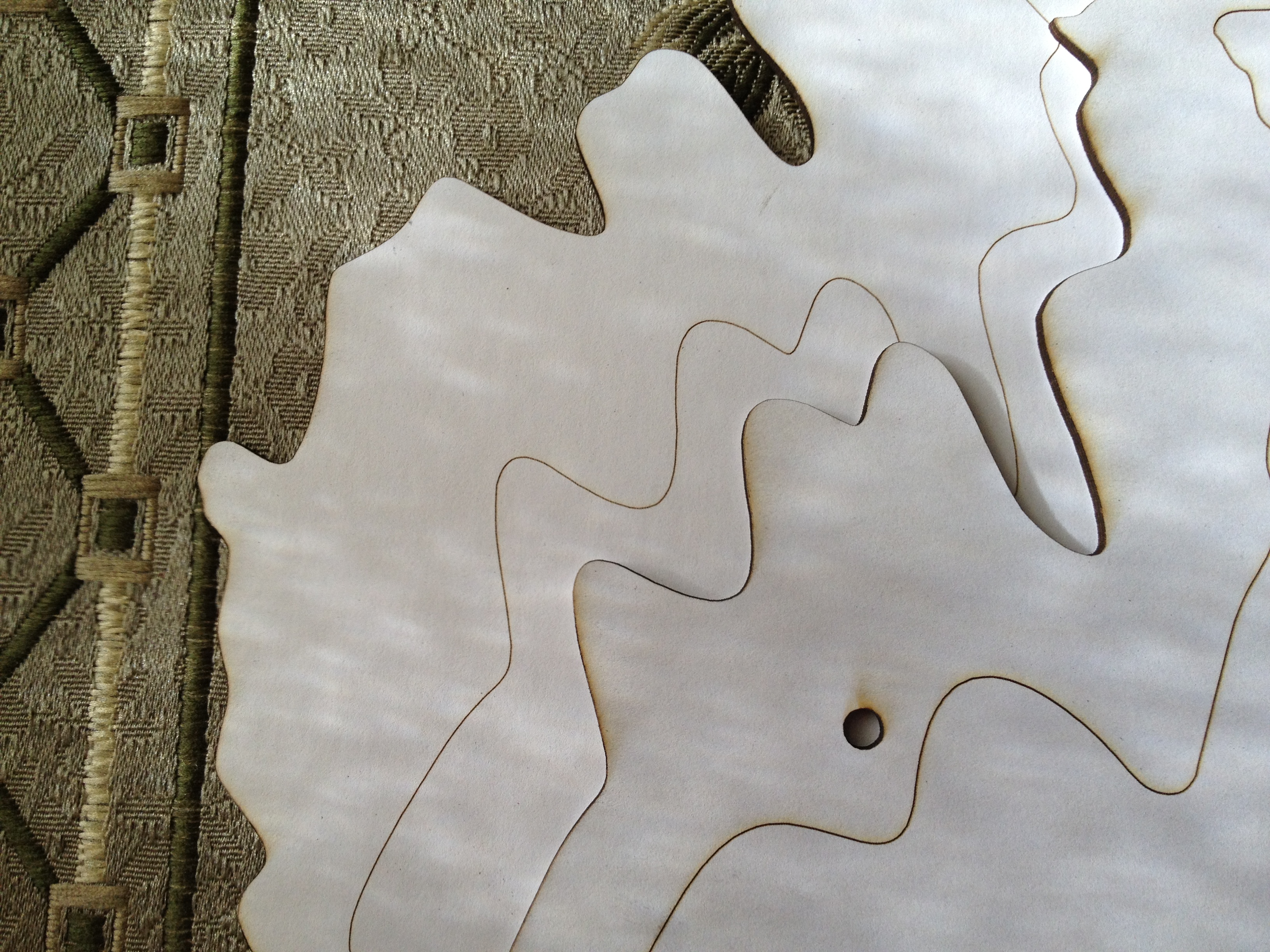
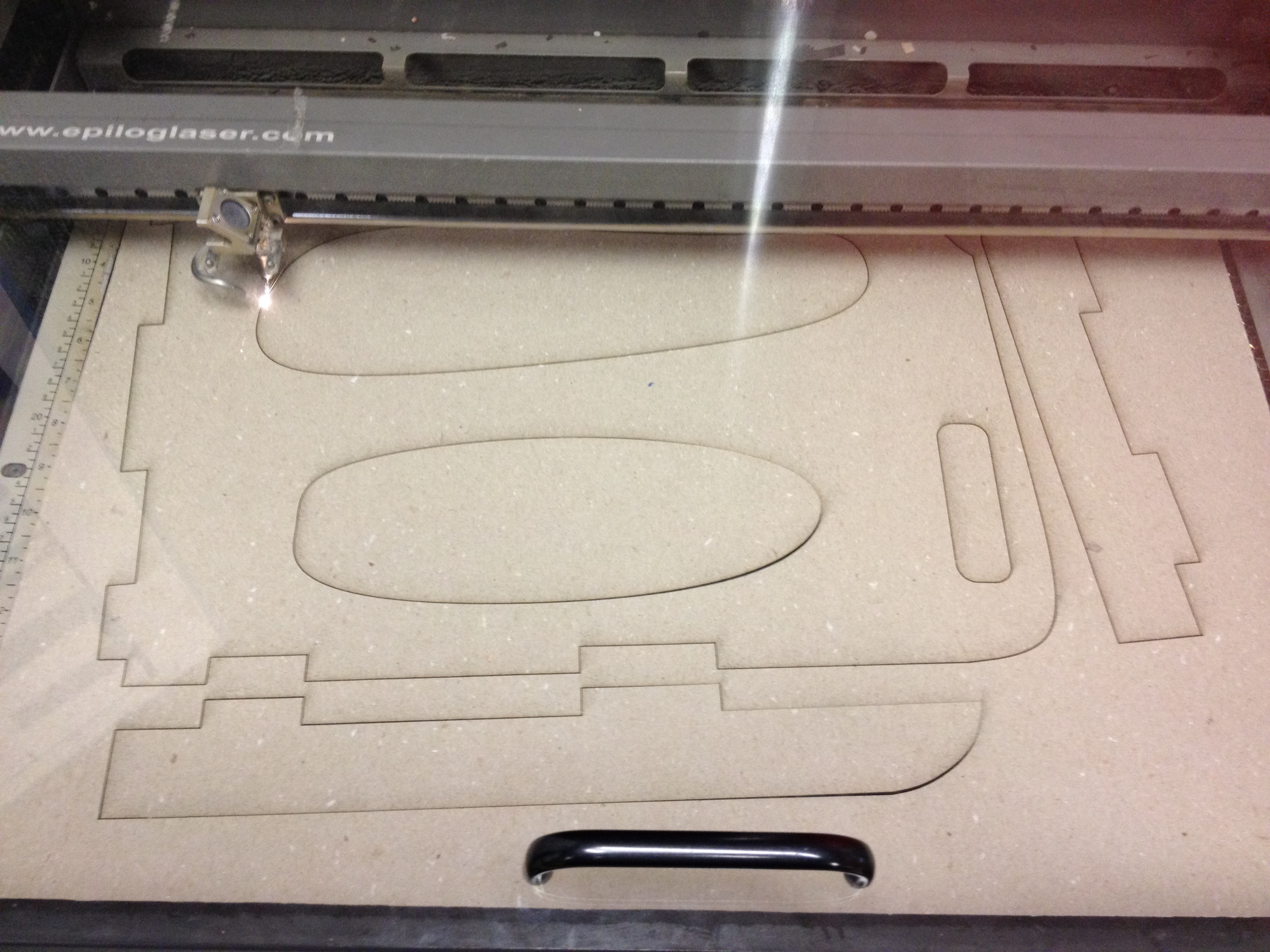
In my smaller model I laser cut small holes in each layer that I could use to align them. In this bigger version I had a flash of inspiration. I would do two passes on each laser cut. The first pass would be with laser settings that would cut through the mat board. Then I'd mark to not print the layers I just cut and mark to print the very next layer above each. With the laser set to barely mark the surface I'd "cut" them. This left each piece marked with an outline of where the piece above it would go. No more need for registration holes.
Cut the Model
This next step takes a few hours of Epilog Helix laser cutter time, so be ready to sit for a while. It helps to review your plans and write down what you plan to do for each cut - I didn't and so I made a few mistakes.
A written plan can really save you a lot of time at the laser cutter. You should write up a plan like this:
Sheet 1
Cut layers: 820, 740, 600, 500
Mark layers: 860, 780, 640, 540
Sheet 2
etc
Assembly
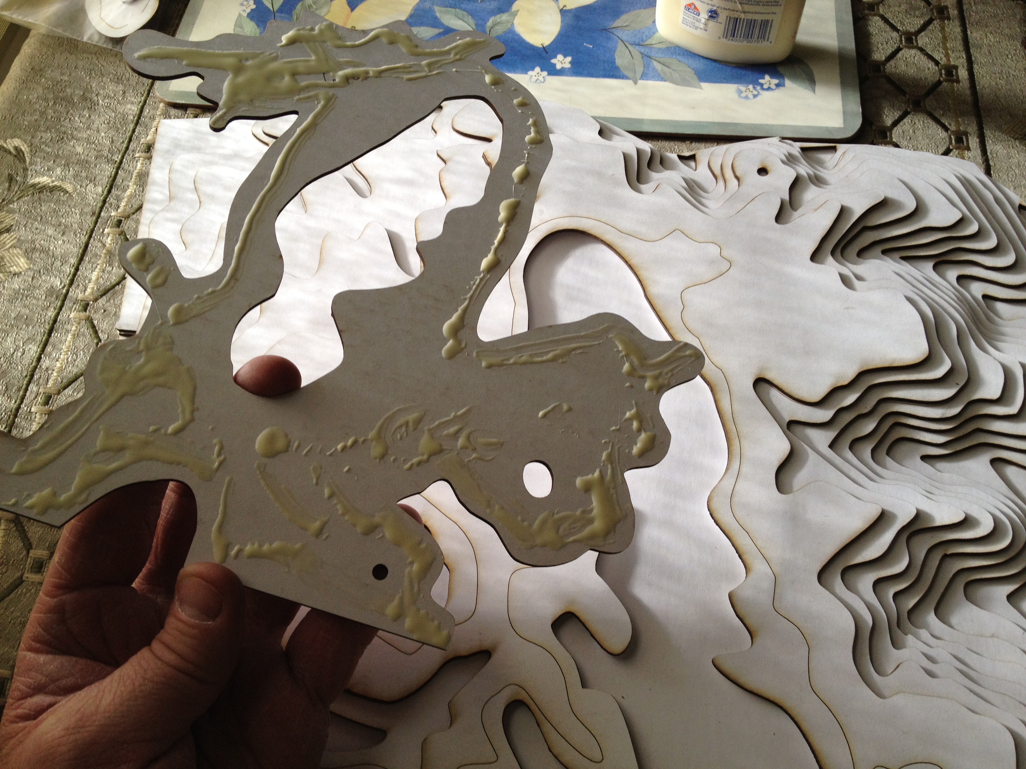
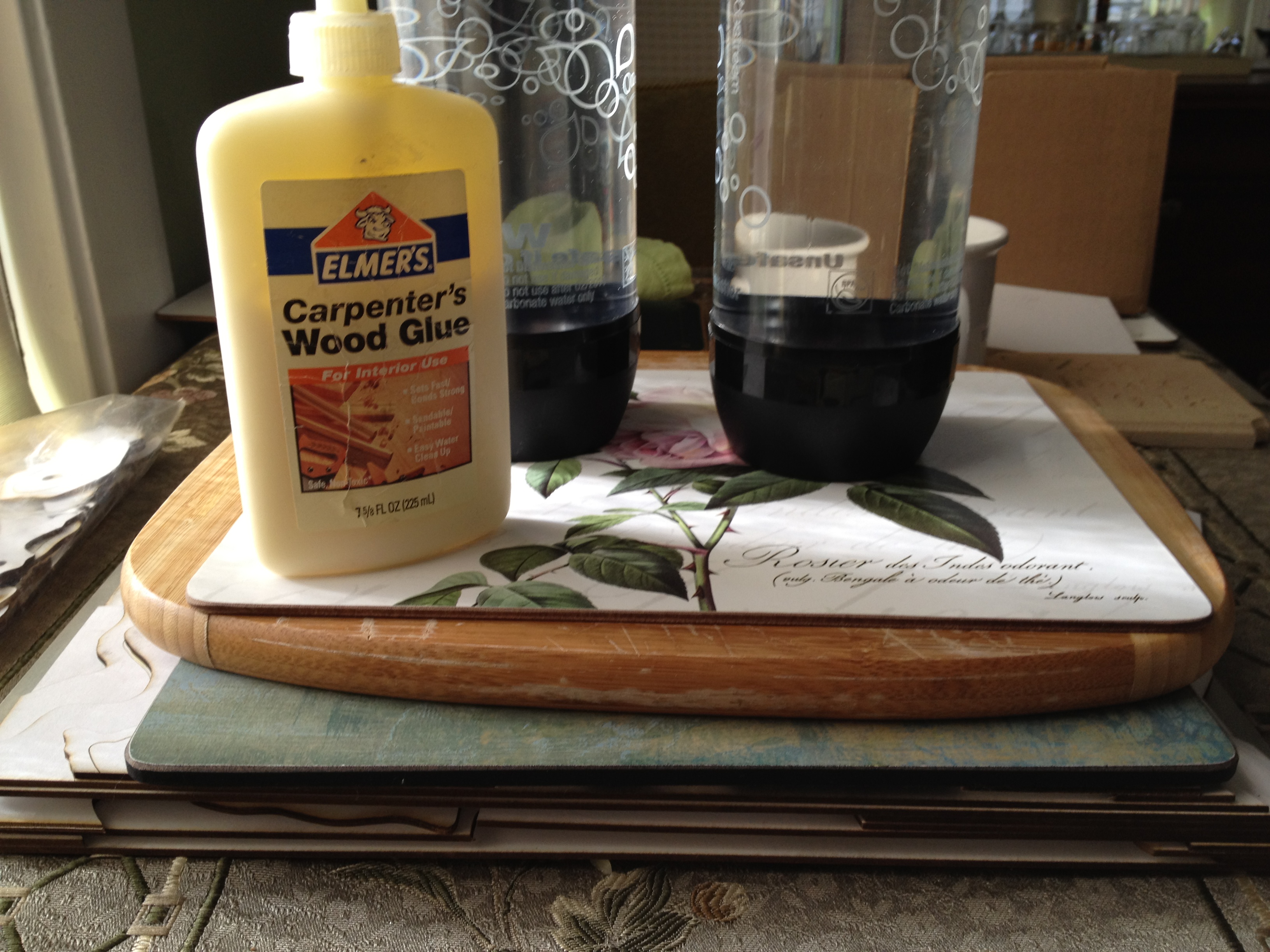
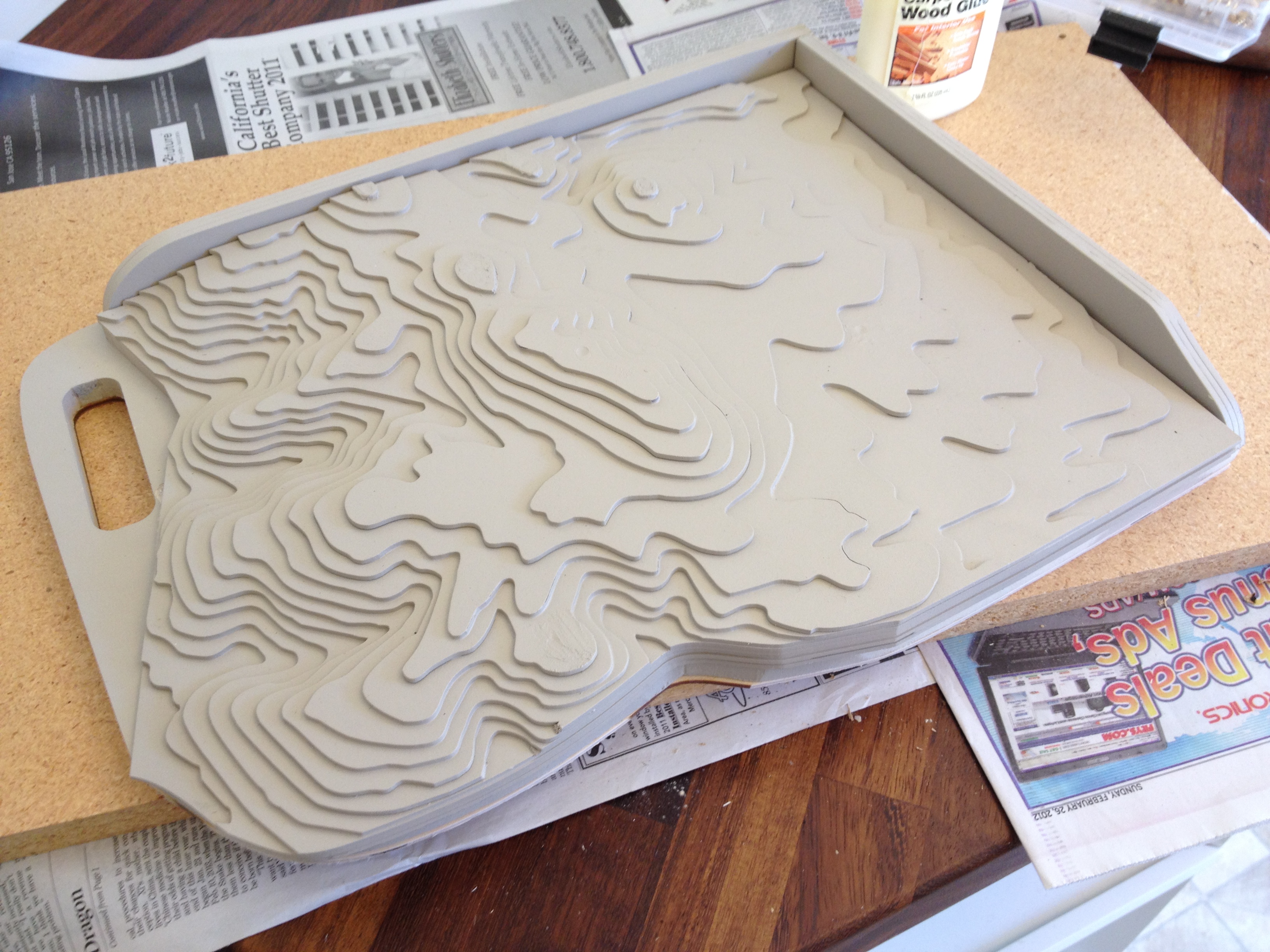
This is fun and simple. Just lay out your pieces. Start from the bottom one. Apply a thin ribbon of glue around the inside edges of the marked contour. Put the next piece on it and press it in place. I put something heavy on it and let it sit for five minutes. Then move on to the next layer.
Design The Case
I found that being hollow the finished model was a little too flexible. I also thought it would be cool to look inside the hollow part, but I found that the edges just looked unfinished. The small model was getting beat up and I realized that I'd need to have something to protect this bigger version. These thoughts all coalesced into the need for a case. I decided to do a simple case.
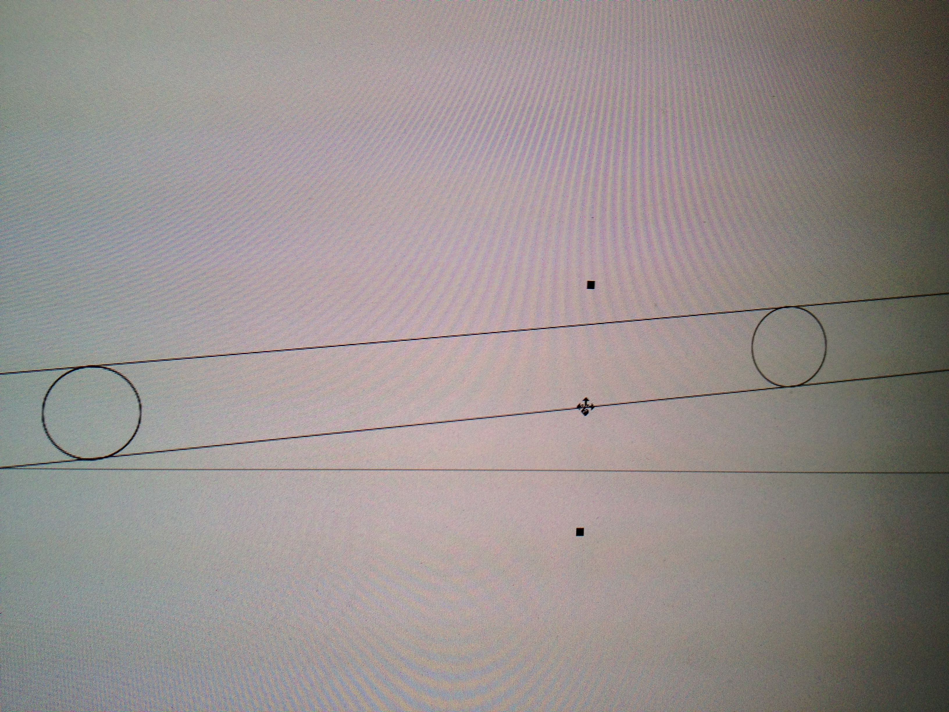
My first step was to create another layer in CorelDraw and copy the outline of the model into that layer. My case would have small walls on the two sides I wanted to hide. My plan was to use 0.5 inch MDF so I extended the two sides by that much. To make sure I moved the edge line just that amount I created two 0.5 inch circles and placed them touching the existing edge line. Then I copied the edge line so that it was on the other side of the circles. Now delete the circles and you have a new edge in the correct location.
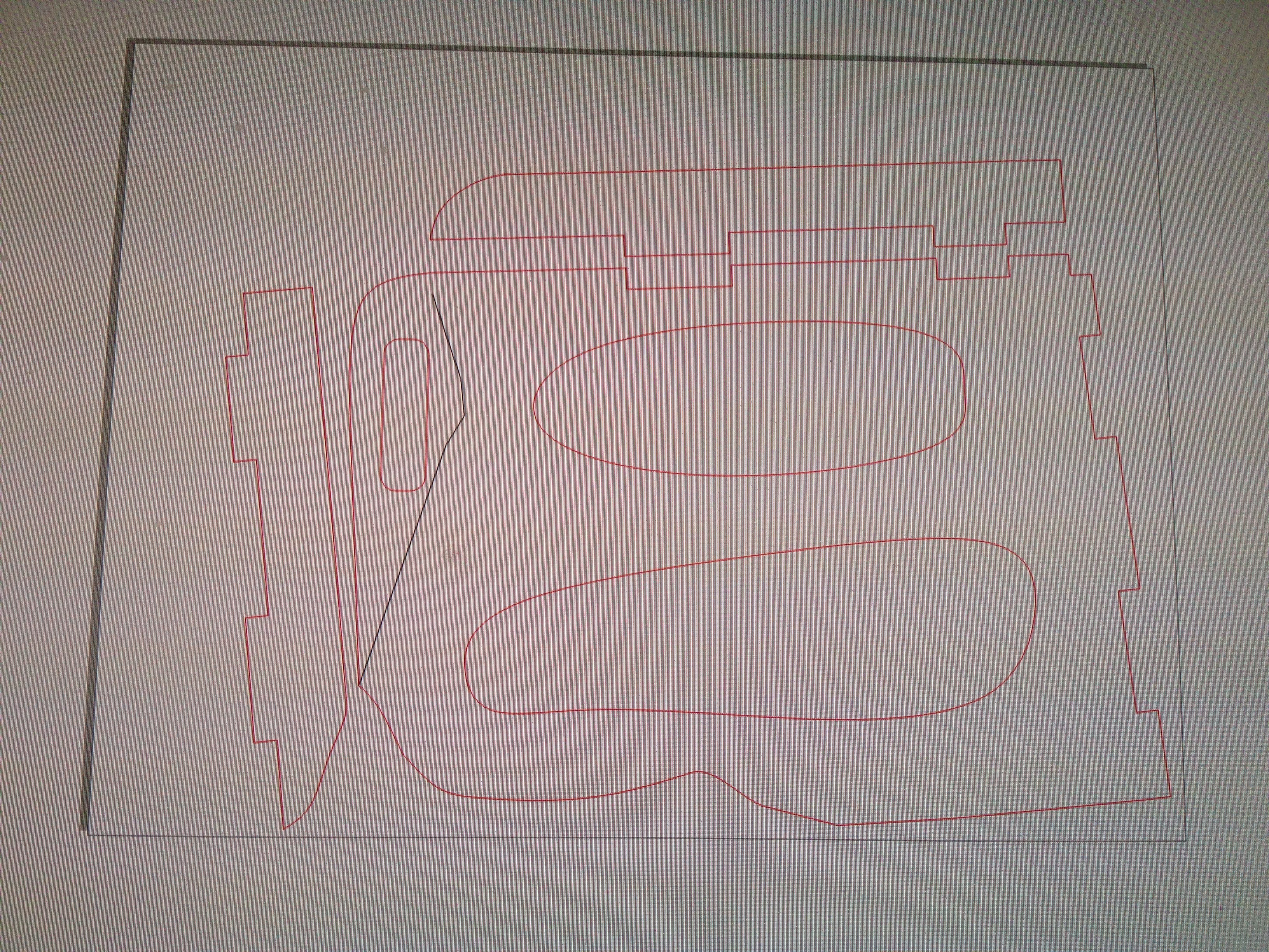
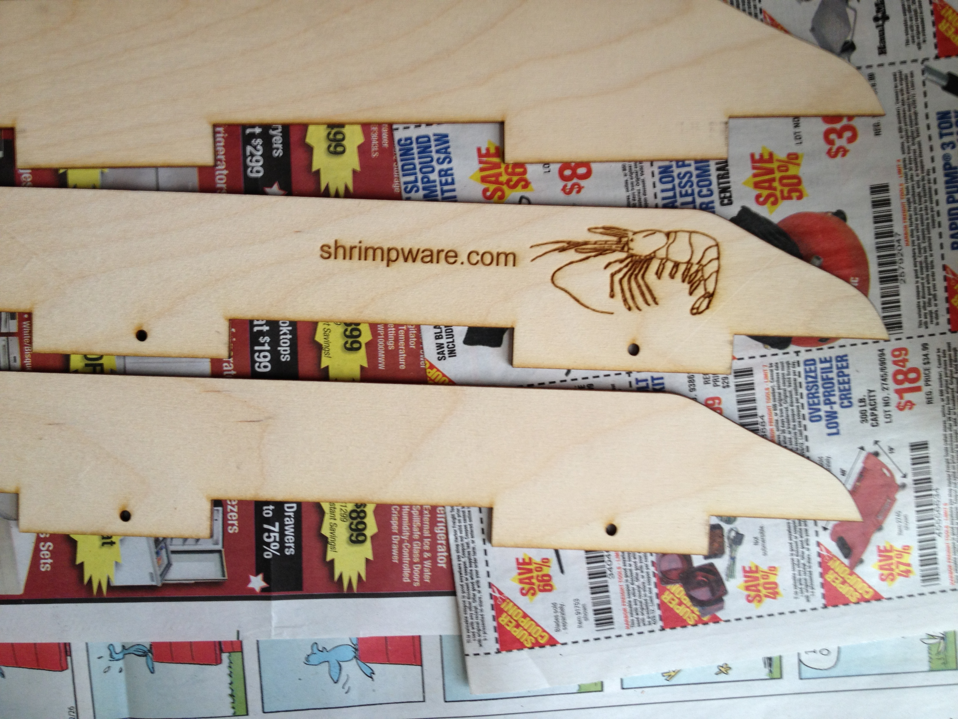
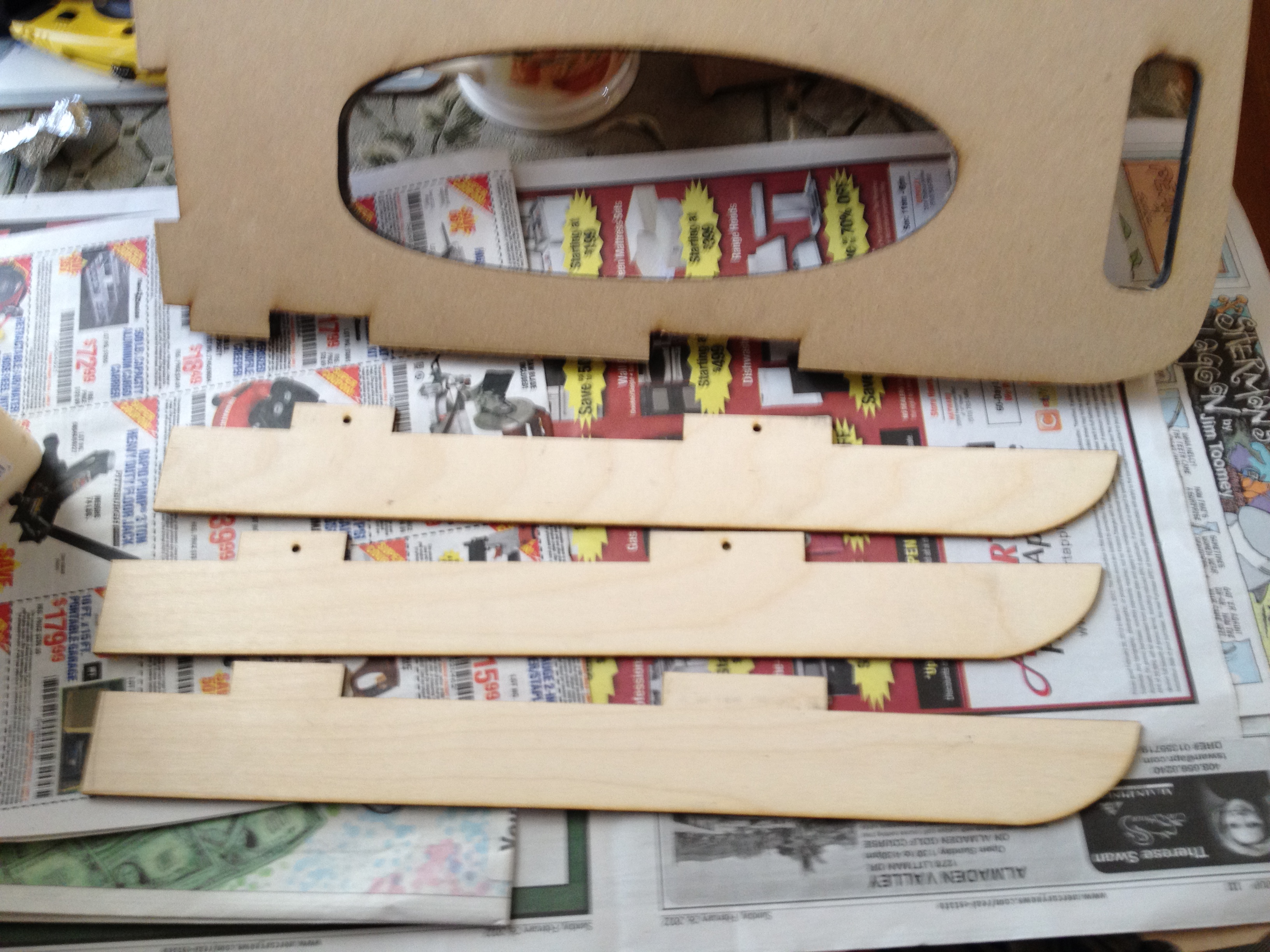
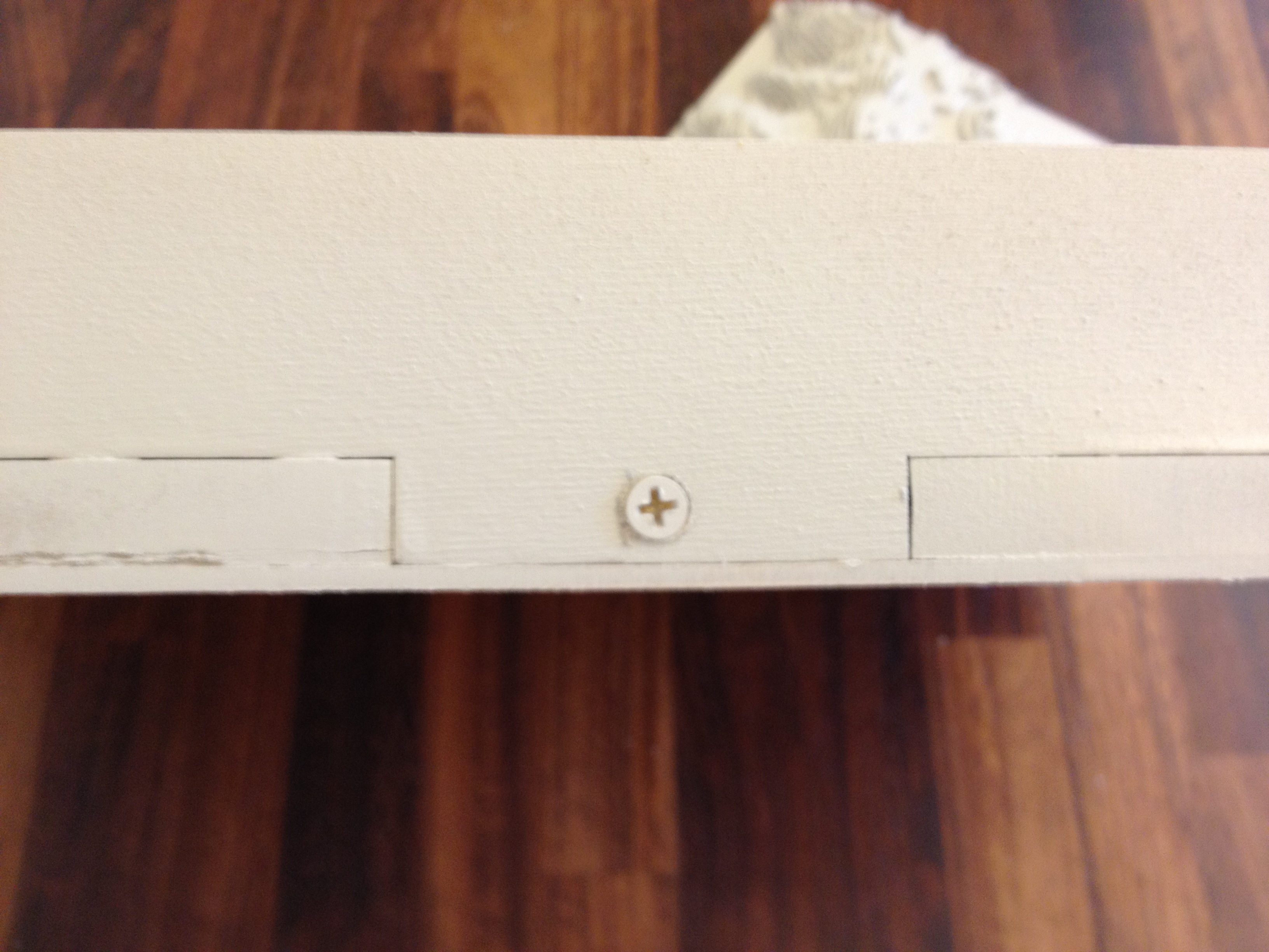
I added a simple finger joint to each edge. Using CorelDraw's node editing tool I added nodes to the outer edge in places where I wanted to make the finger. Then draw a new line from the node to the old edge line; CorelDraw alerts you when the line is perpendicular. A bit more editing and you have a finger joint line. Now select all those lines and group them into one object.
To make the walls you copy the finger joint line you just made. Now you know for sure that the walls will fit in the base because they are cut with the exact same line. I wanted my walls to be as high as the model is tall. Again I made a few circles of the correct size and laid them against my finger joint line. A new line that touches the circles on the other side is in the exact right location.
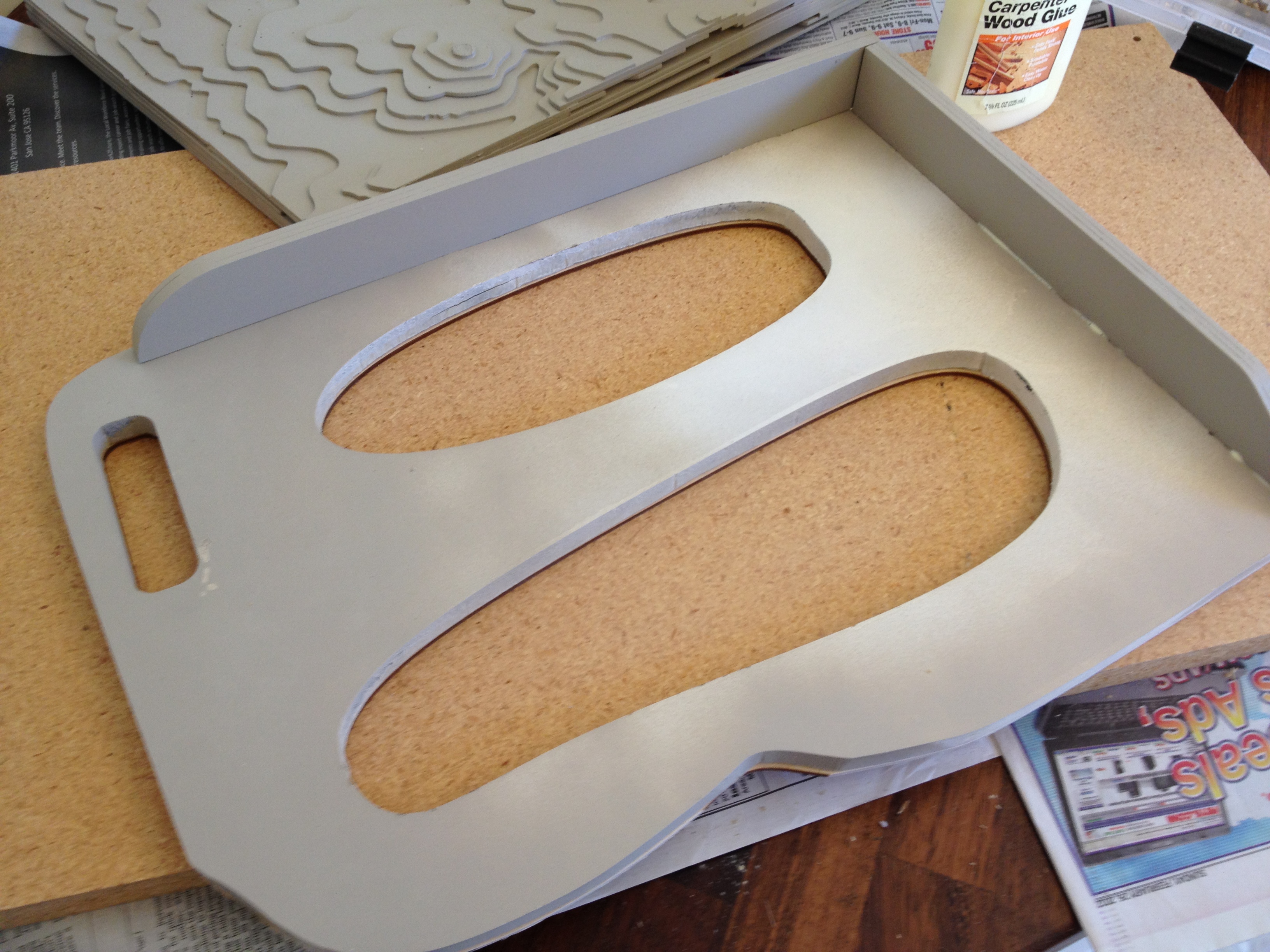
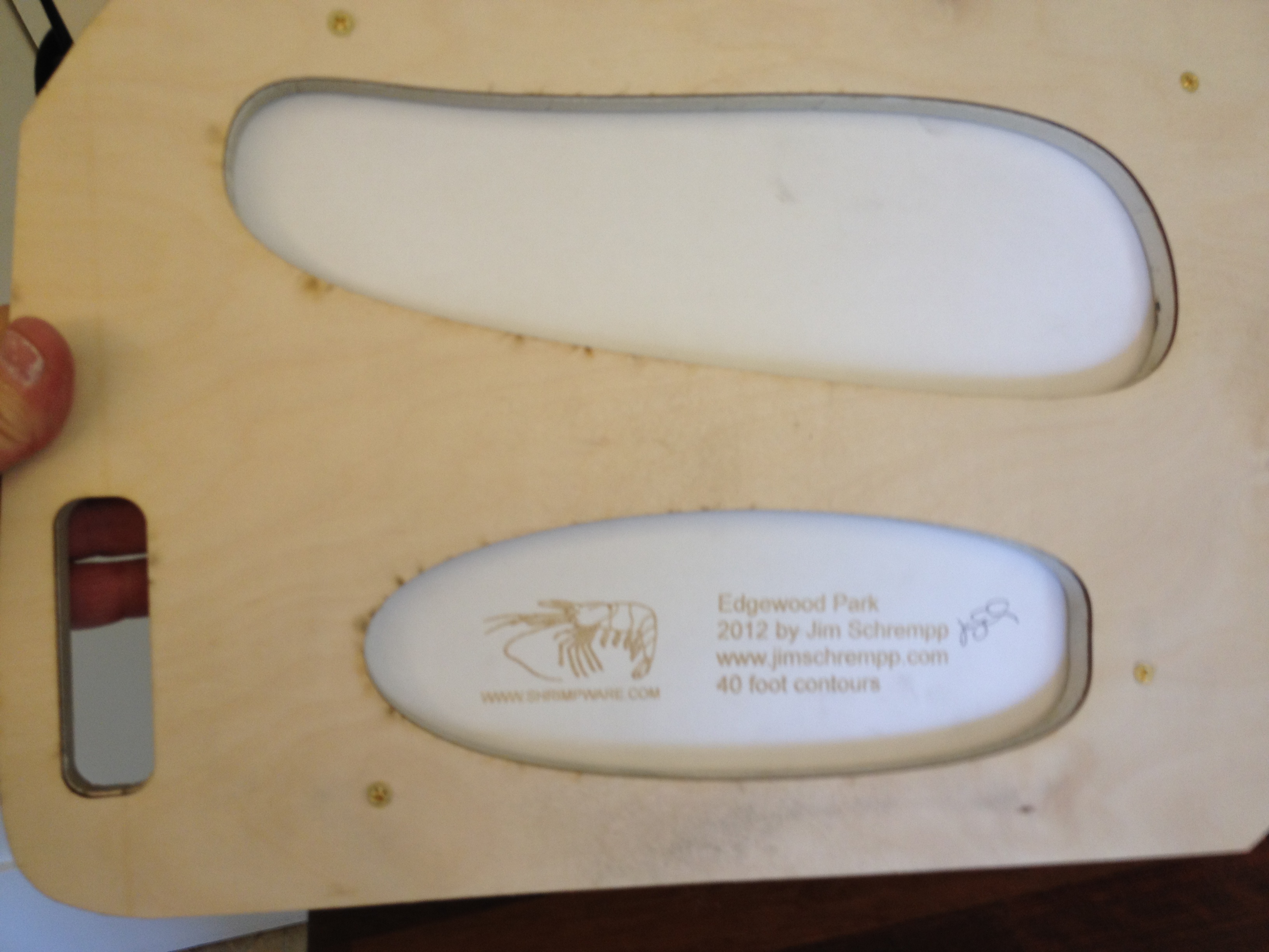
I also wanted a handle so I extended the base and added a 5 x 1 inch rounded slot (I have big hands).
Cut and Assemble the Case
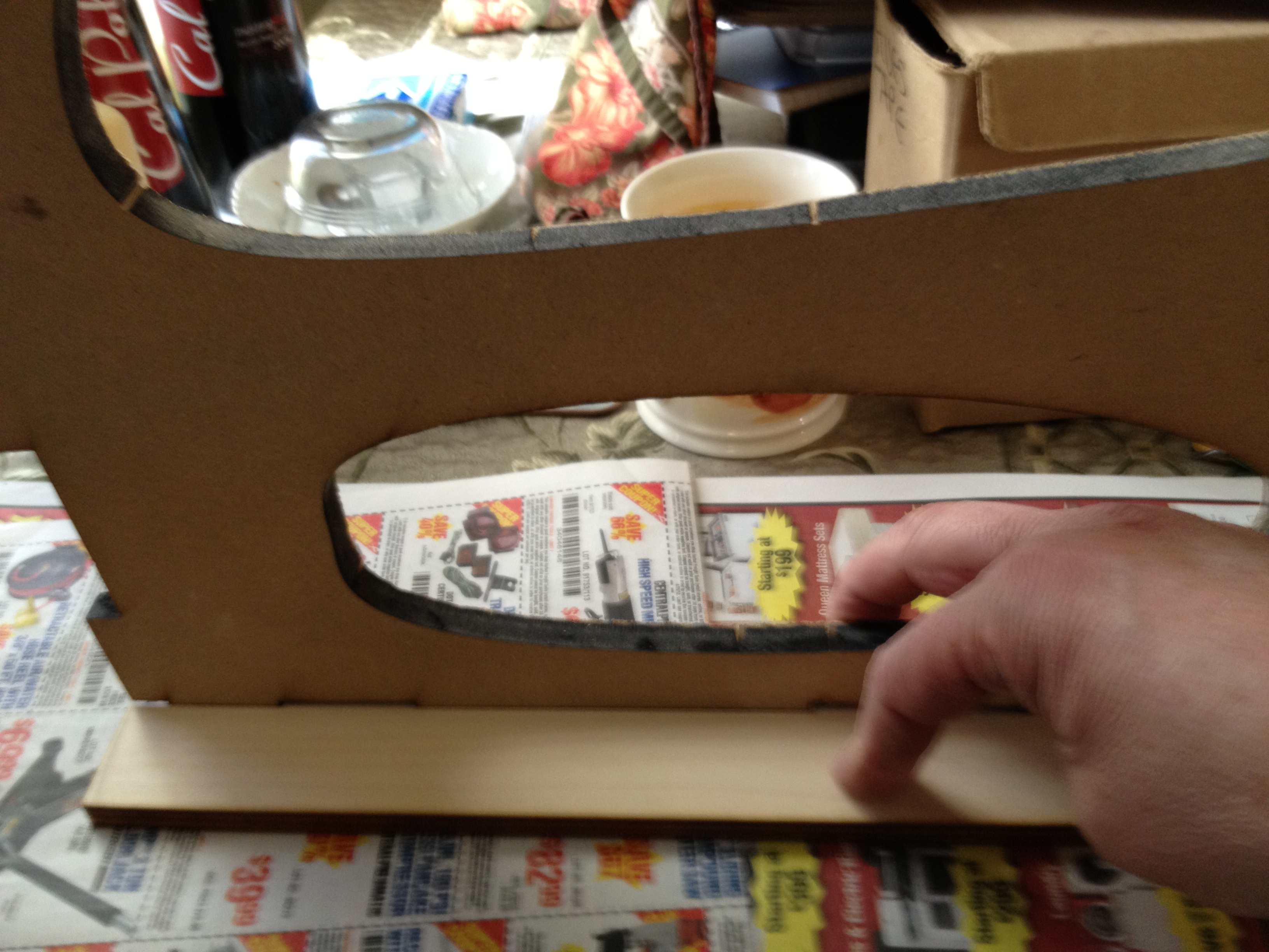
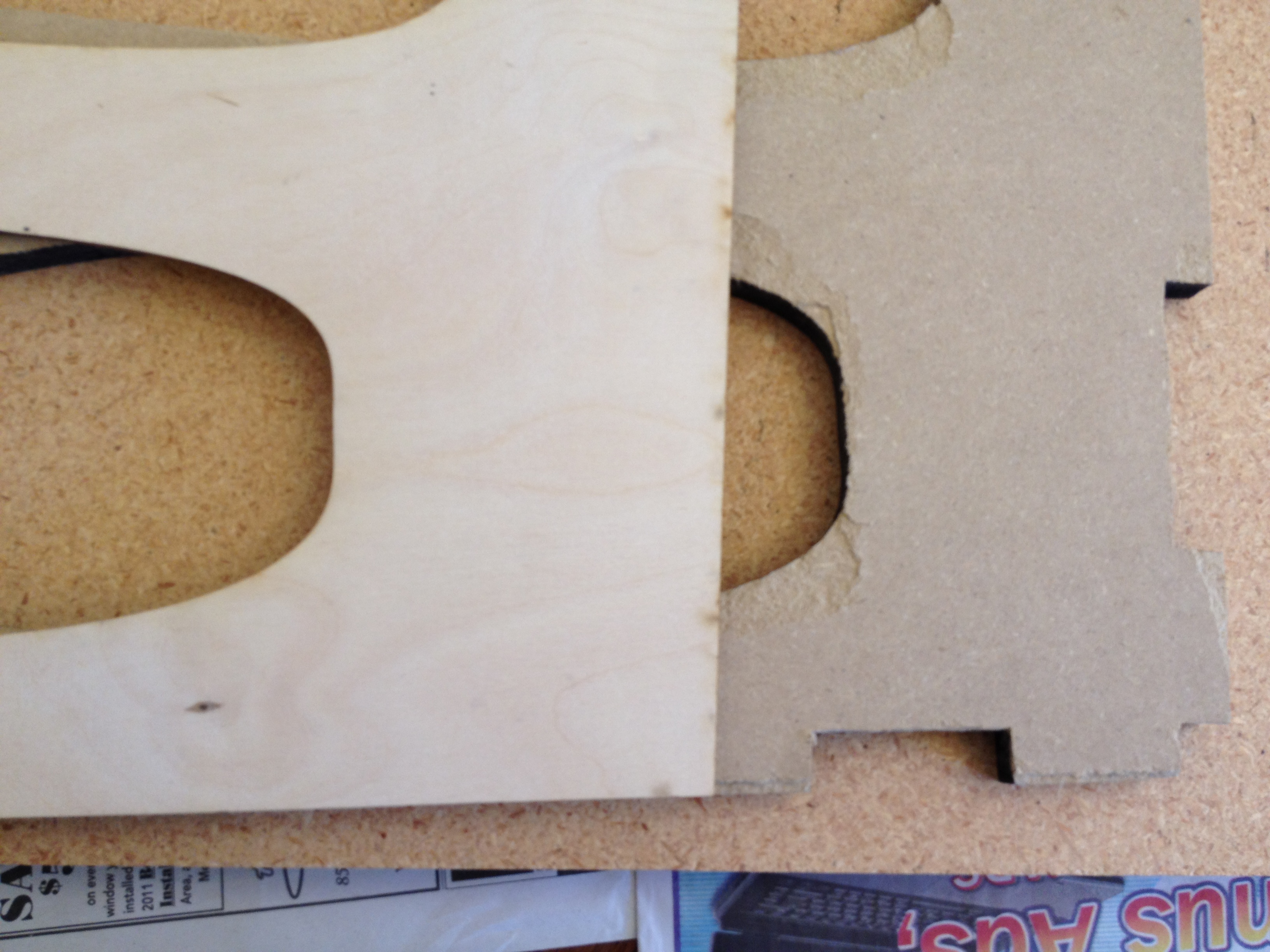
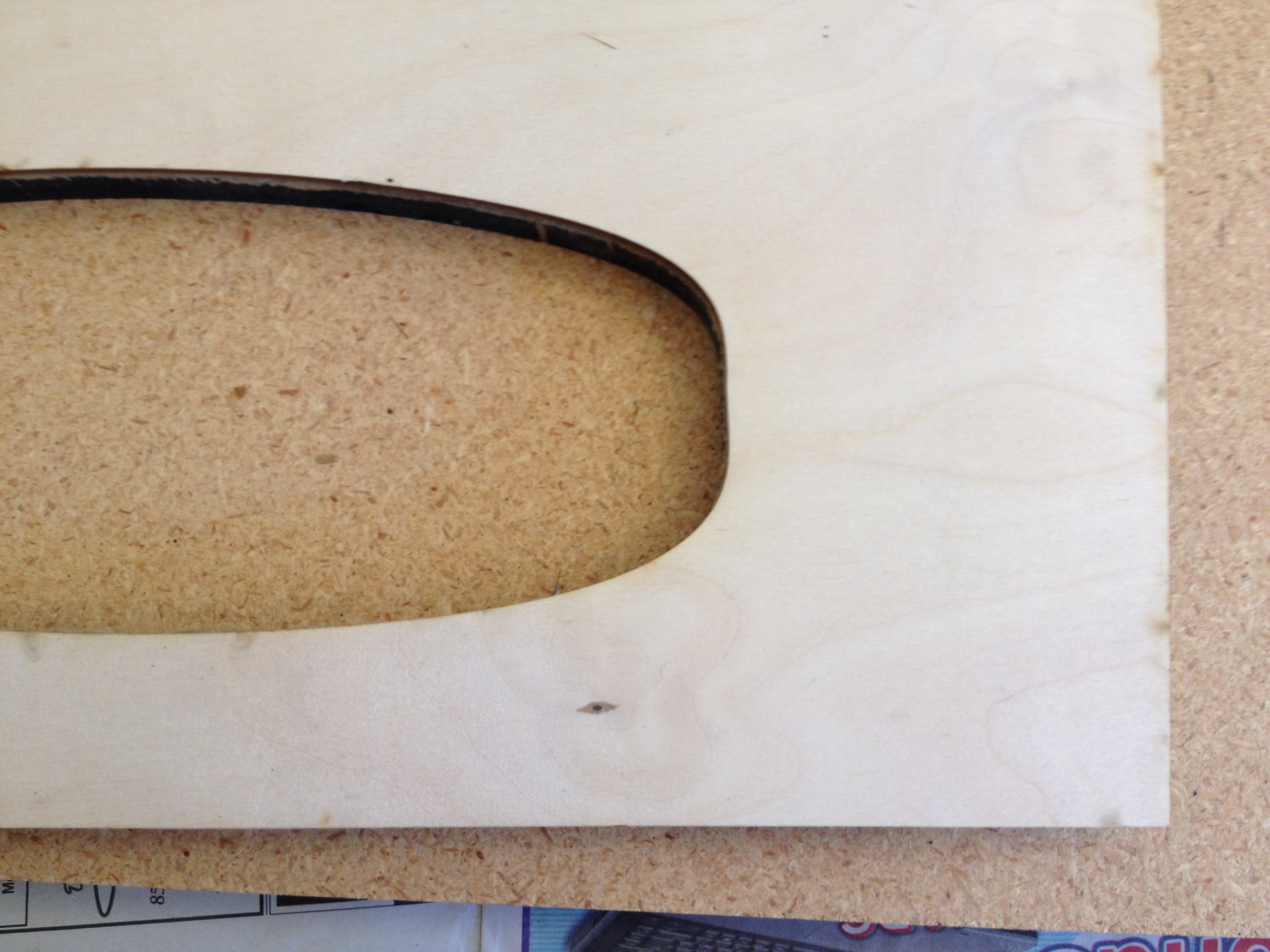
My first case was cut from 0.5 inch MDF, but it didn't work so well. The laser could never really cut through the MDF. It had plenty of power but I think the 0.5 inch thickness put the laser so out of focus that it never cut fully through the material. I used a jig saw to free the pieces and cleaned them up with a vertical belt sander (thankfully TechShop has all the tools I needed) but the result was still bogus.
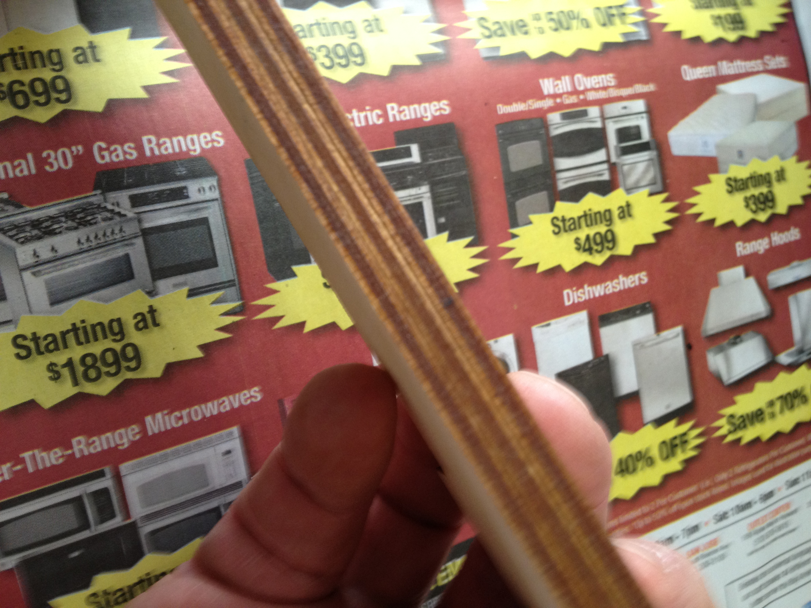
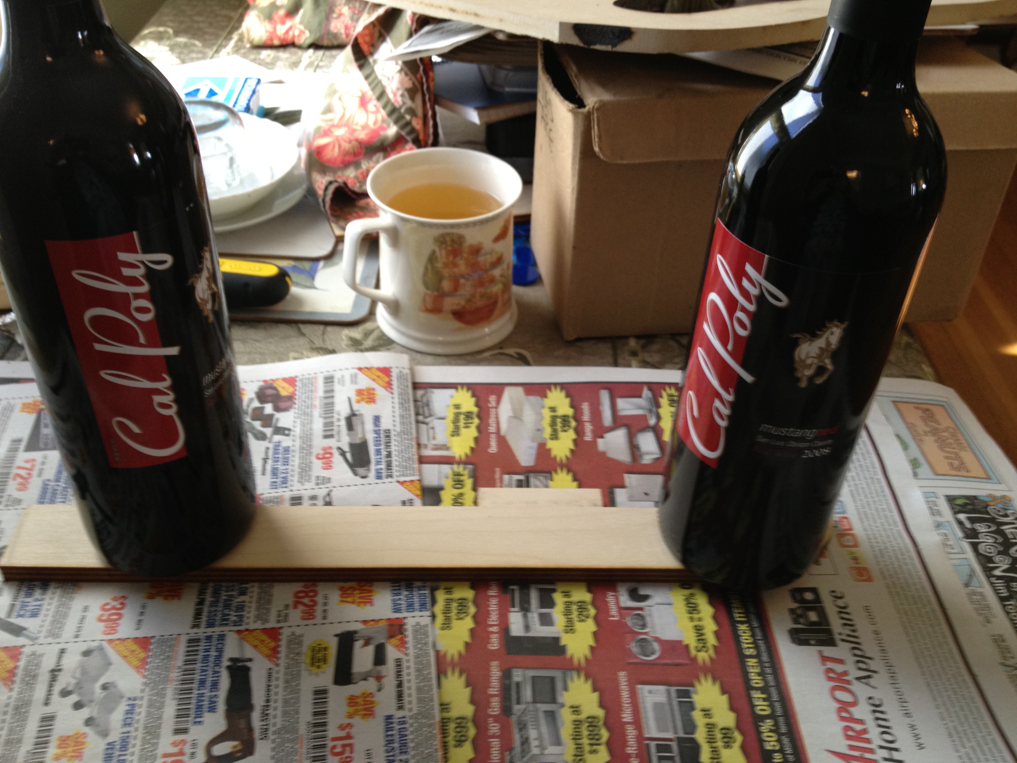
I had some thin plywood left over from another project so I cut the sides from that. I cut three copies of each side and glued them together to make a solid piece. All together they were just under 0.5 inch so I had to mark and sand the bottom finger joints just a bit. I also cut one large piece to glue over the bottom to hide all the crummy parts of my earlier MDF experience. If I were to do this again (and I might) I'd make the bottom of the case out of three sheets of the plywood too; it looks much sharper.
Final Assembly
I used one inch brass screws to hold the finger joints together. I also used 2 inch brass wood screws to hold the model to the case. Be careful when you place these screws! You want to screw into a part of the model that has overlapping mat board, and you don't want to have the screw break through the top of your model.
Finishing
I used spray paint and the TechShop spray booth. It was nice to have the ventilation and to keep the mess at TechShop instead of my garage. I first coated the model with Bin spray primer, two coats. Be careful to spray lightly. You don't want the mat board to flex with the liquid and you don't want drips. Then three final coats with sand colored Rust-oleum fine textured finish spray paint. It looks dreamy.
As you can see in the video, the whole thing came out great. I now have a true scale model of Edgewood park to carry around with me. After I show friends the small pocket model I pull the big one out of my trunk to another extended series of "wow's." With all the positive feedback I'm getting from my friends, I wonder what landscape I'll do next?
Enjoy it. Make it.
Jim