Traintracker Dashboard - Metro Bilbao
by SuperCat373 in Circuits > Electronics
1825 Views, 18 Favorites, 0 Comments
Traintracker Dashboard - Metro Bilbao
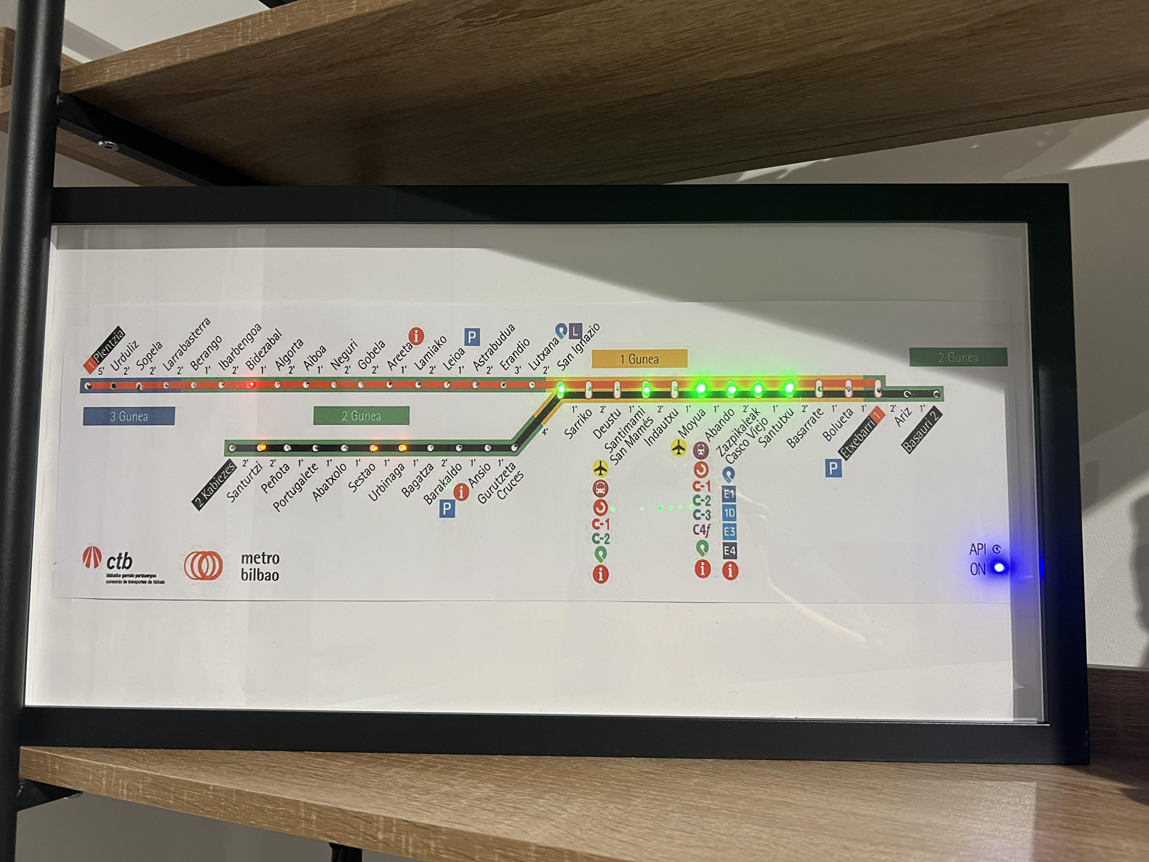
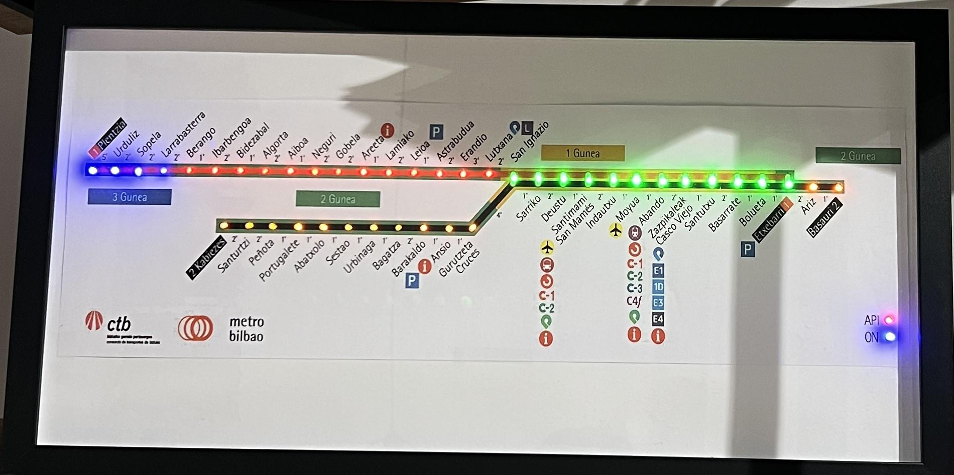
This project includes a detailed guide on how to make a dashboard that shows the active trains via led indicators on Metro Bilbao's underground network, based on the API of CTB. (Consorcio de Transportes de Bizkaia) See disclaimer at the bottom.
Features
- Train position indication for Lines 1 and 2.
- Blink when two trains coincide in the same station.
- Real-time data from CTB's API. (updates every 3 minutes)
- ON state indication.
- API disconnection indication.
- WiFi connectivity. (required)
Github Page (code)
Supplies
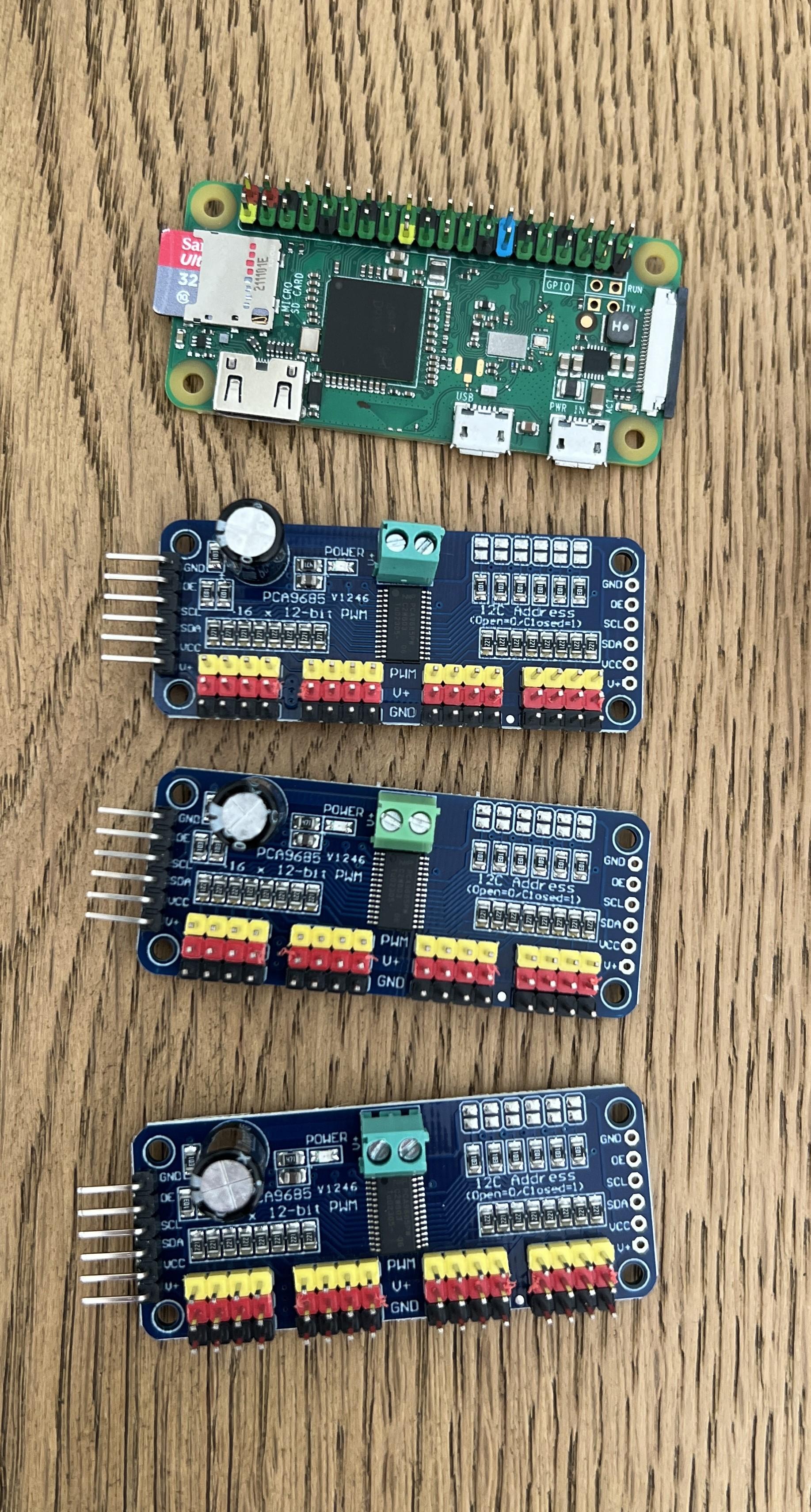
Materials:
- RÖDALM Picture Frame (55x28cm)
- Presoldered 3mm LEDS
- 3x PCA9685 boards
- Raspberry Pi Zero W
- RPI 0 Power Supply (5V 2,5A)
- Micro SD Card
- A2 copy of the map (97% scale)
- White paperboard
Tools:
- Dupont crimping tool
- Pliers
- Drill
- 3mm drill bit
- Soldering iron
Downloads
Prepare the LEDS
Crimp all 44 LEDS with their corresponding dupont connectors and test that you've crimped the correctly. This setup requires:
- 14 red leds.
- 13 orange leds.
- 12 green leds.
- 5 blue leds.
Advice: I would crimp at least 2 extra of each color just in case you get a faulty one.
Set the Address on the PCA9685 Boards
You can follow this guide from Adafruit to set the addresses on all 3 boards, they come predefined with address 0x40. In order to do this you'll need a soldering iron.
- Board 0: address 0x40, no bridges.
- Board 1: address 0x41, bridge A0 pin.
- Board 2: address 0x42, bridge A1 pin.
Connect All Boards and Leds
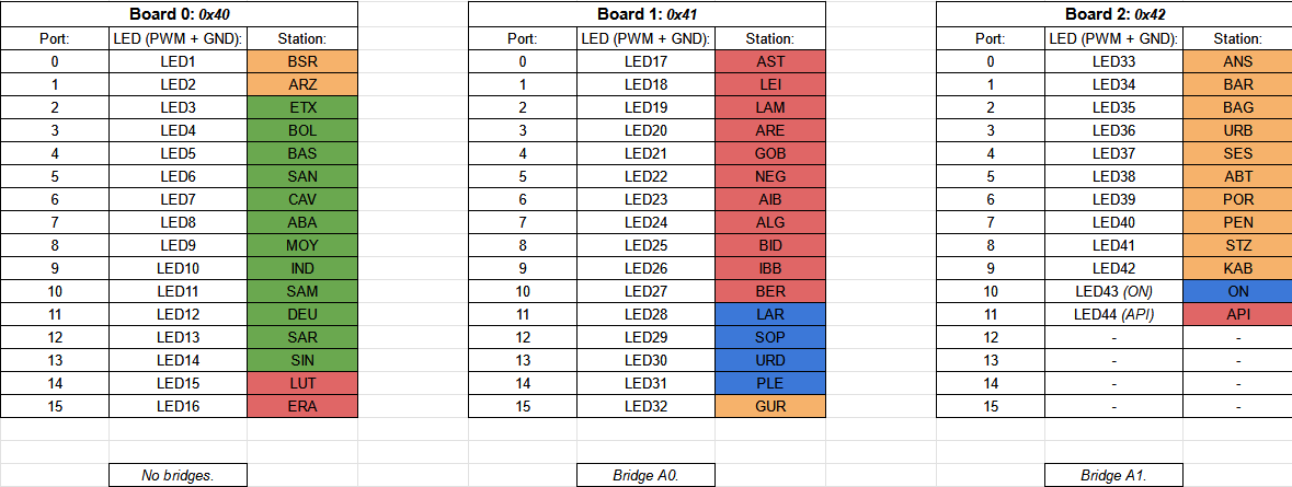
Follow the port map on the attached image in order to connect all leds to their corresponding ports. (PWM and GND)
Daisy-chain all boards according to this guide in Adafruit's page.
Connect to the boards to the Pi
Board 0 needs to be connected to the Raspberry Pi via I2C.
Port map:
- SDA (GPIO2) -> SDA on board 0.
- SCL (GPIO3) -> SCL on board 0.
- 5V -> 5V on board 0.
- GND - > GND on board 0.
Prepare the Raspberry Pi
For this project you'll need to flash Raspberry Pi OS Lite (32 bit) into a Micro SD card with Raspberry Pi Imager. During the setup wizard you must include you WiFi password and SSID, apart from the credentials that will be used later on for SSH.
Connect to the Pi With SSH & Install Python3
Connect to the Pi via SSH. You can use Putty or your Windows' shell.
Update all dependencies.
Enable I2C on your pi.
- Go to Interface Options > I2C > Enable.
Install the required packages.
Test I2C devices:
You should see:
Install the Test Script to Test All LEDS
Create a new directory and move to it.
Add the test script (test.py)
Paste the contents and exit (CTRL + X, CTRL + Y, ENTER)
Run the test script (all leds should blink)
Downloads
Install the Main and Off Scripts
Add the main script (main.py) and off script (off.py)
Paste the contents and exit (CTRL + X, CTRL + Y, ENTER)
Run the Main Script so it connects to the API and lights up the corresponding LEDS
Setup a Cron Job to Run and Stop It Automatically
Setup crontab
Paste this on the bottom of the file
Save and exit
This should leave the script running at the background at 16:00 PM and stop it at 23:00 PM.
Prepare the Frame
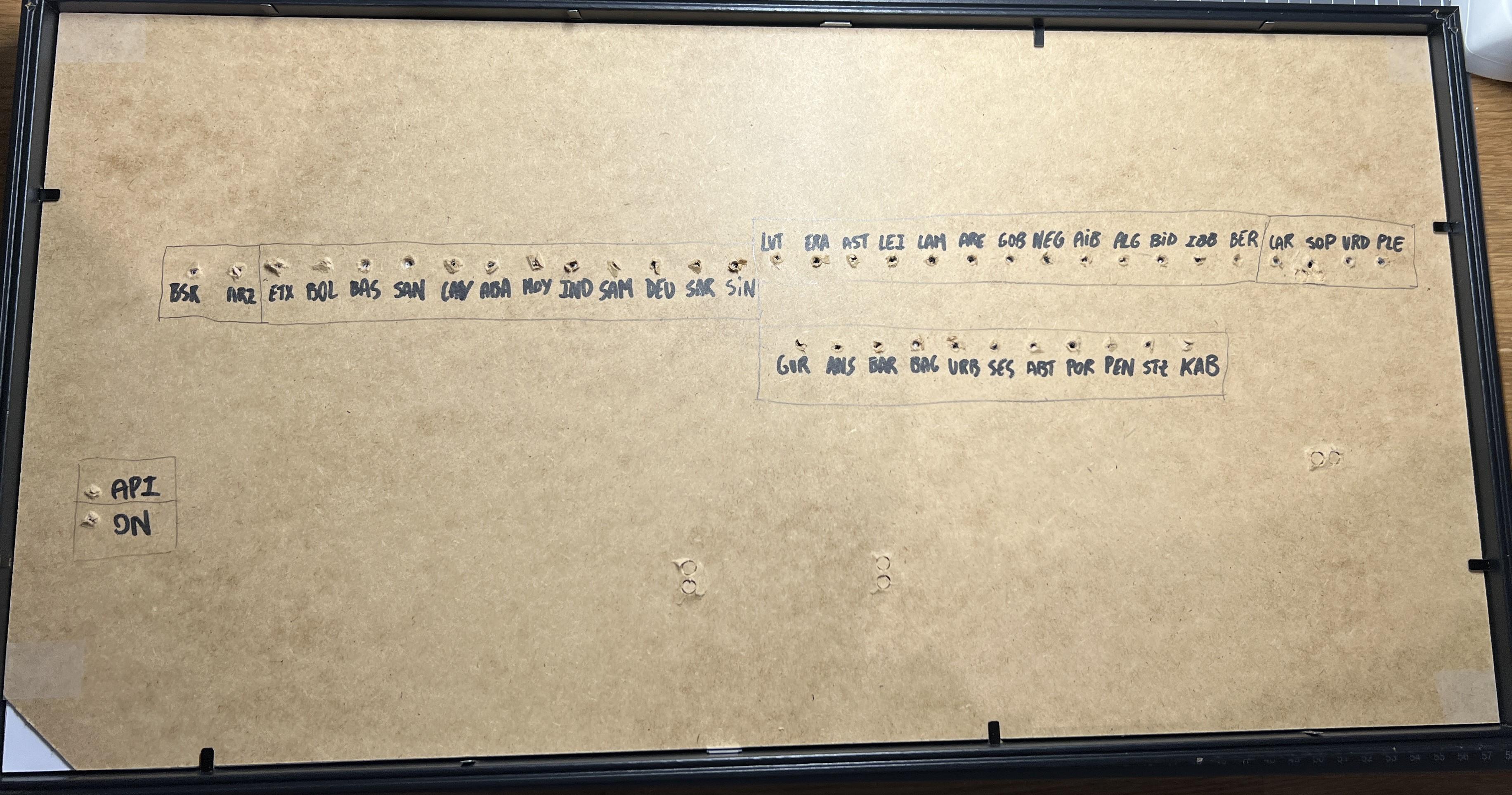

1. Cut the map and center it on the white paperboard.
2. Drill the corresponding holes on the paperboard and the frame's backplate.
3. Write the Stations' name to help you place the LEDS.
Insert the Leds and Secure the With Electrical Tape
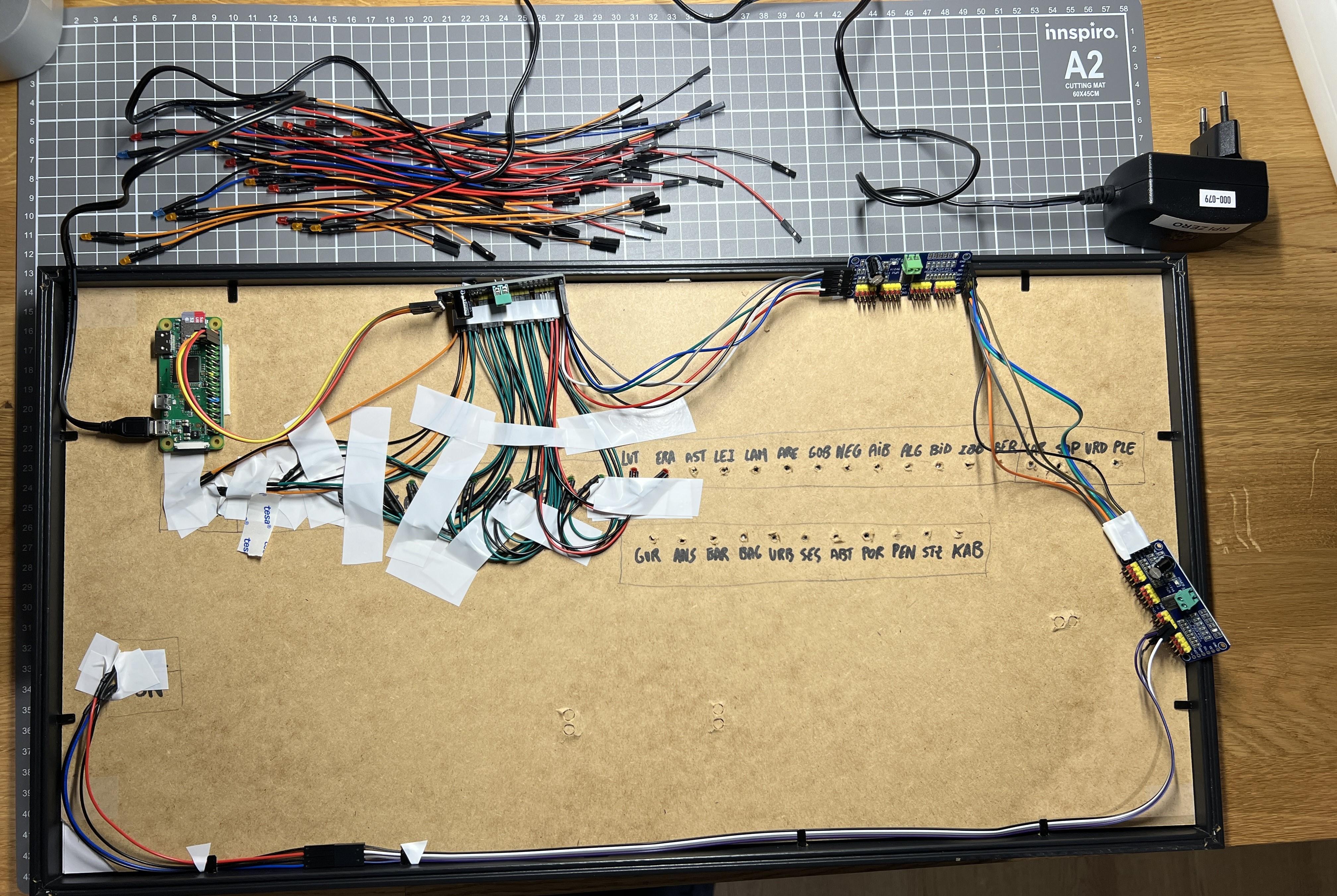
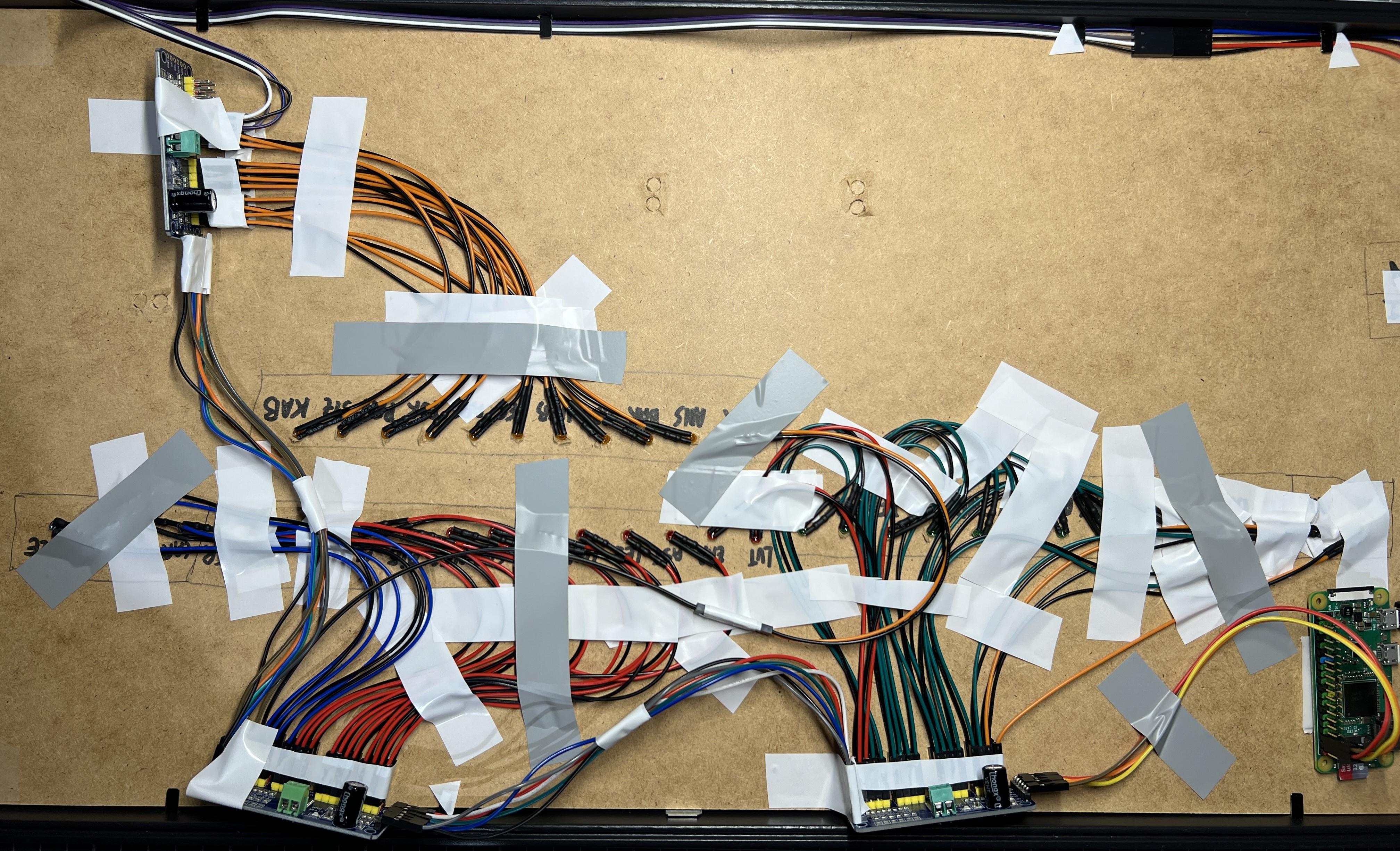
*I know using electrical tape to secure the LEDS is a janky-way, but it was the easiest to remove them :)
Test Everything and Enjoy!
Disclaimer!! (and Sources)
Disclaimer
This project is not endorsed by or afiliated to Metro Bilbao or CTB in any way, this is just a project with educational and recreative purposes. The use of the API is under the Terms And Conditions of CTB. The trademarks and logos of Metro Bilbao and CTB are of their property and shall not be used with commercial purposes, as they belong to them.
Sources and Credit
Inspiration:
- u/Vonmule's setup
- u/Abdanir's setup
- u/YoungDimmaDome's setup
- Original Map (by Laukatu)
- Metro Bilbao's Website
- CTB's Website
- API Link
Feel free to leave your suggestions or pictures if you decide to make it or adapt it! Happy Tinkering!! :)