TrafficLight+
Hello Everyone! We proud to showcase our project for our Interactive Design course. We created a circuit system to help manage the flow of traffic. We call it TrafficLight+!
Supplies
- 1 Adafruit Metro Mini
- 1 Adafruit NeoPixel Ring/16 LEDs
- 1 Adafruit Micro SD Card/32 GBs
- 1 SD Card Reader
- 4 Piezo Buzzers
- 4 Round Force Sensitive Resistors(FSRs)
- 4 10kΩ resistors
- 1 470Ω resistor
- [blank] wires
Software Requirements
- Arduino IDE 2.3.4 Software
- Arduino Uno Mini Board / any open port
- Installing Libraries:
- Accessing the Arduino Libraries on the program itself, search for “Neopixel Ring” and install that library. It will give your program access to the NeoPixel Ring library functions
- Next, search for “SD” and install this library. It will allow the program to utilize the SD card functions.
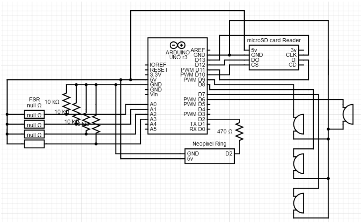
Circuit Design


On the breadboard, make sure the Metro Mini is installed on the bridge space between each side of the board.
From there, you can begin installing the core components. Starting with the SD card reader:
- Plug it in close to the metro mini
- Use a wire to plug the 5V pin from the card reader to the 5V bus on the breadboard.
- Use another write to plug the GNDs together through the bus
- Make sure Digital pins 10-13 are free because the SD card reader needs them to write the data.
- The CLK pin should have a wire connected to pin 13
- The DO pin connects to pin 12
- The DI pin connects to pin 11
- The CS pin connects to pin 10
Now grab the 4 FSRs and 10kΩ resistors. Align the FSRs along one side of the breadboard. Make sure there is 4 pin space between them all.
- Grab 4 wires and connect one to each of the FSR’s GND pins, plug them into analog pins A0-A3.
- Next, grab the 10kΩ resistors and connect each one into the GND pin and the GND bus on the breadboard
- Grab 4 more wires and connect the 5V pins of each FSR into the 5V bus using these wires
The Buzzer’s don’t need resistors, all we need is 8 wires total to install them.
- Align all 4 buzzers along the other side of the breadboard with at least 4 pins between them as space.
- Using 4 wires, connect each buzzer to one of the 4 digital pins on the metro mini. Specifically pins 6-9.
- Using the last 4 wires, connect each buzzer into the GND bus on the breadboard
Finally, the Neopixel ring needs 4 wires and the 470Ω resistor.
- Connecting one wire to digital pin 2, connect the other end on any open space on the breadboard.
- Utilizing the 470Ω resister, align it with the wire on the breadboard. Using another wire, connect it to the other end of the resistor and attach the wire to the data input wire of the neopixel ring
- Connect one wire to the GND of the NeoPixel Ring and to the GND bus
- With the final wire, connect it to NeoPixel Ring’s 5V wire and the 5V bus on the breadboard.
Downloads
Soldering the Prototyping Board
.jpeg)


Main Board:
- This board contains three components. The metro mini, SD card reader, and the Neo Pixel Ring
- To install the components on the breakout board, grab 4 headers. one header of length 8 pins for the SD card, two headers of size 13 for the metro mini, and one male headers of size 3 for the NeoPixel Ring.
- using the two headers of size 13, place them in the middle of the board with 5-6 pin spaces between. Under the board, solder the pins outlined above in the circuit design section for all the components in the system.
- Below those headers facing perpendicular, place the 8 size header for the sd card. Solder the pins outlined as well.
- Finally, on the bottom right older the male header for the neo pixel ring.
side boards:
- There will be 4 identical copies of these boards for the 4 buzzers and FSRs.
- instead of a header for the FSRs, we will use clamps to hold them in place as the pins are too short to stay in headers. Place the clamp on the one end of the board and solder it in place.
- on the right side of the clamp solder 1 wire, this is for the 5V wire of the FSR.
- On the left side of the clamp solder another wire, this will be the analog input wire. from there, solder 1 10K ohm resistor connected the analog wire.
- on the other end of the resistor, solder a smaller wire connected to the end of another wire. This other wire will be the GND wire for both the FSR and the Buzzer.
- Moving onto the buzzer, use a header of size 3 (in our picture it's more than 3 because we ran out of parts), and solder one end of the header next to the GND wire.
- On the other end of the header, solder a wire because this will be the Digital Input pin for the buzzer.
Assembly
Once the boards have been soldered in place, you're at the final stretch to begin creating the system.
- Place the components into their respective headers
- Place the wires from each side board into their correct header pins to unite all the boards to the main board.
- Launching Arduino and creating a new sketch, copy and paste the code from the attached zip file into the new sketch and upload the code. System should respond to the FSR input and work as a traffic light.
Downloads
Operating Instructions
To begin setting up the TrafficLight+ make sure the NeoPixel Ring is at the heart of your intersection. Install the SD card and Metro Mini in a safe and secure location out of the reach of non-employees. Using the 4 Piezo Buzzers and Round Force Sensitive Resistors, install 1 of each together on each of the 4 roads in the intersection.
Once the installation is complete, turning on the system should be the last manual aspect of operation. The TrafficLight+ system will begin collecting data on SD cards about the traffic around the intersection while managing said traffic by utilizing the FSRs to determine which road should take priority. Once the lights change from green to red and vice versa, the buzzer on that current road will alert any nearby pedestrians about the light change.
Potential Improvements
For future iterations of our TrafficLight+ project, adding a medium vibration sensor component would add another layer to the data gathered from the system. We would install these new sensors near the neopixel ring to keep track of the number of cars that pass through that particular road on the intersection. This would work by measuring how often the vibrations occur once the light turns green. This way each new vibration would be equivalent to another car that drove past that light. Once this data is gathered, it will be recorded onto the SD card for city planners to use.
Instead of using Buzzers, future versions of the project would involve speakers that gave clearer sound cues such as voicelines. This way it’s easier for pedestrians to understand the current state of the intersection
Finally, a major improvement could be the logic of the timers. Since we had to create the timers ourselves, that was another layer of difficulty when it came to implementing the traffic logic into our code. Because of this, utilizing a built-in time library in future versions would make this system work more smoother and easier on the developers.