Traffic Light Controller
This is a simple circuit of a traffic light controller , this is designed using the tinkerCAD software .
This is a simple working model for the beginners who are learning Robotics . This is my 2nd working model , it is easy to design and work in it .
Required Components

Below the following are the components required to make a Traffic Light Controller :
1] Breadboard 1No.
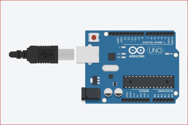
2] Arduino 1No.
3] RGB LEDs 3 No.
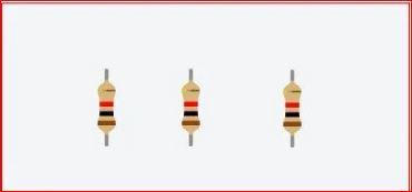
4] Resistors 3 No.
5] Connecting Wires 4 No.
Assembling
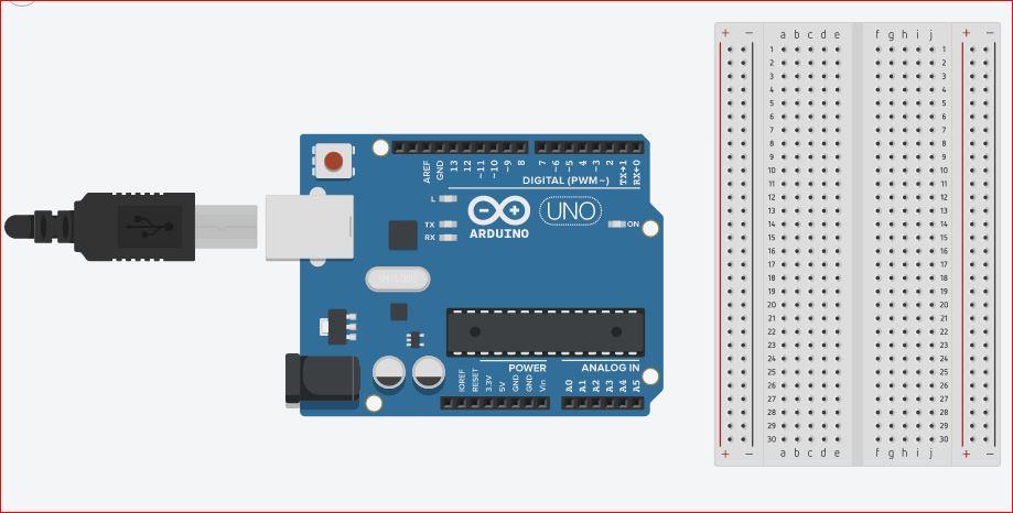
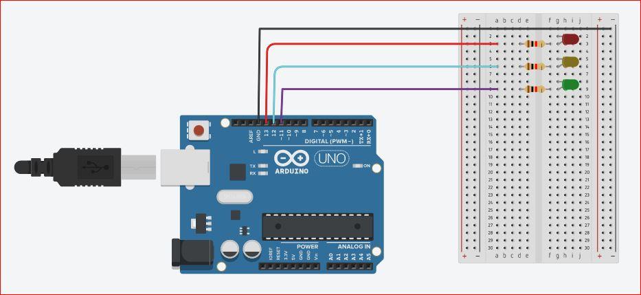
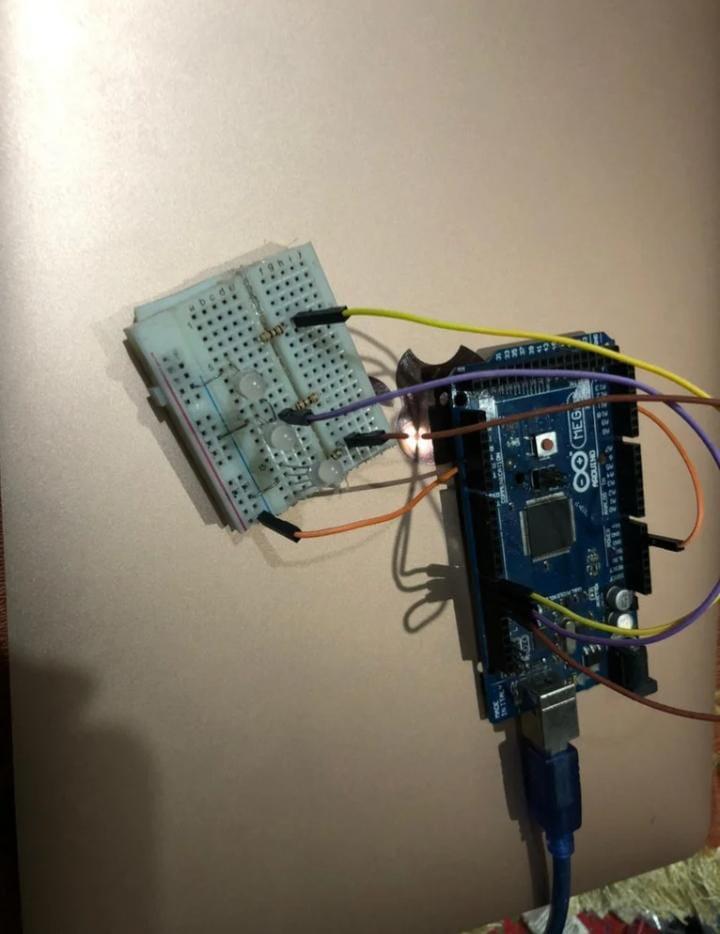
First take 1 Breadboard small and Arduino , now rotate the Breadboard 180 degrees .
Connecting Resistors
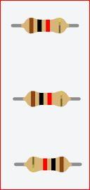
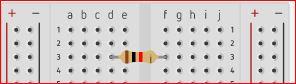
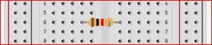
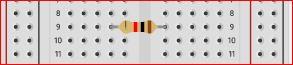
Take 3 Resistors and rotate it to 90 degree
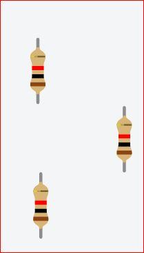
Now connect it to the breadboard ,Terminal Strips 4th Hole Row [d] to 2nd Terminal Strips 1st Hole Row
Connect the 3 Resistors as shown in the images .
Connecting LED Bulbs

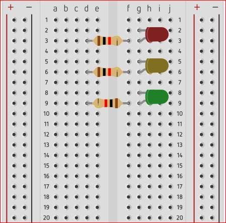
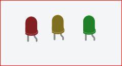
Take 3 LED Bulbs in RED , YELLOW and REEN in colors , and rotate it in 90 degrees towards right .
Connect the LED bulbs to the Breadboard as shown in the second image .
Connecting Wires
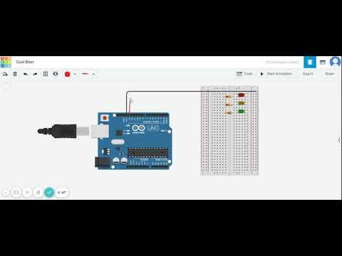
Now, here we are going to connect the wires .
Follow the given video for connecting the wires .
Coding
In the whole process coding is the most important one and the last step . Now you to code the program and run them .
This is the code done me to run the Arduino IDE.
// variables
int YELLOW = 9;
int GREEN= 10;
int RED = 8;
int DELAY GREEN = 5000;
int DELAY YELLOW = 2000;
int DELAY RED = 5000;
// basic functions void setup()
{
pinMode(GREEN, OUTPUT);
pinMode(YELLOW, OUTPUT);
pinMode(RED, OUTPUT);
}
void loop()
{
red_light();
delay(DELAY_RED);
yellow_light();
delay(DELAY_YELLOW); delay(DELAY_GREEN);
green_light();
delay(DELAY_GREEN);
}
void green light()
{ digitalWrite(GREEN, HIGH);
digitalWrite(YELLOW, LOW);
digitalWrite(RED, LOW);
}
void yellow_light()
digitalWrite(GREEN, LOW);
digitalWrite(YELLOW, HIGH);
digitalWrite(RED, LOW); }
{
void red_light()
{
digitalWrite(GREEN, LOW);
digitalWrite(YELLOW, LOW);
digitalWrite(RED, HIGH);
}