Traffic Light Controller
Building Arduino Traffic Controller was my first time working on Arduino as a beginner. It was a fun project as I enjoyed assembling all the parts of the system and writing coding lines. If you too are a beginner using arduino, a traffic light controller is a must-try project due to it's simplicity.
Required Gadgets
I used Mega Arduino for the project. Apart from the basic Arduino, you will need the following things to complete the project:
- A breadboard
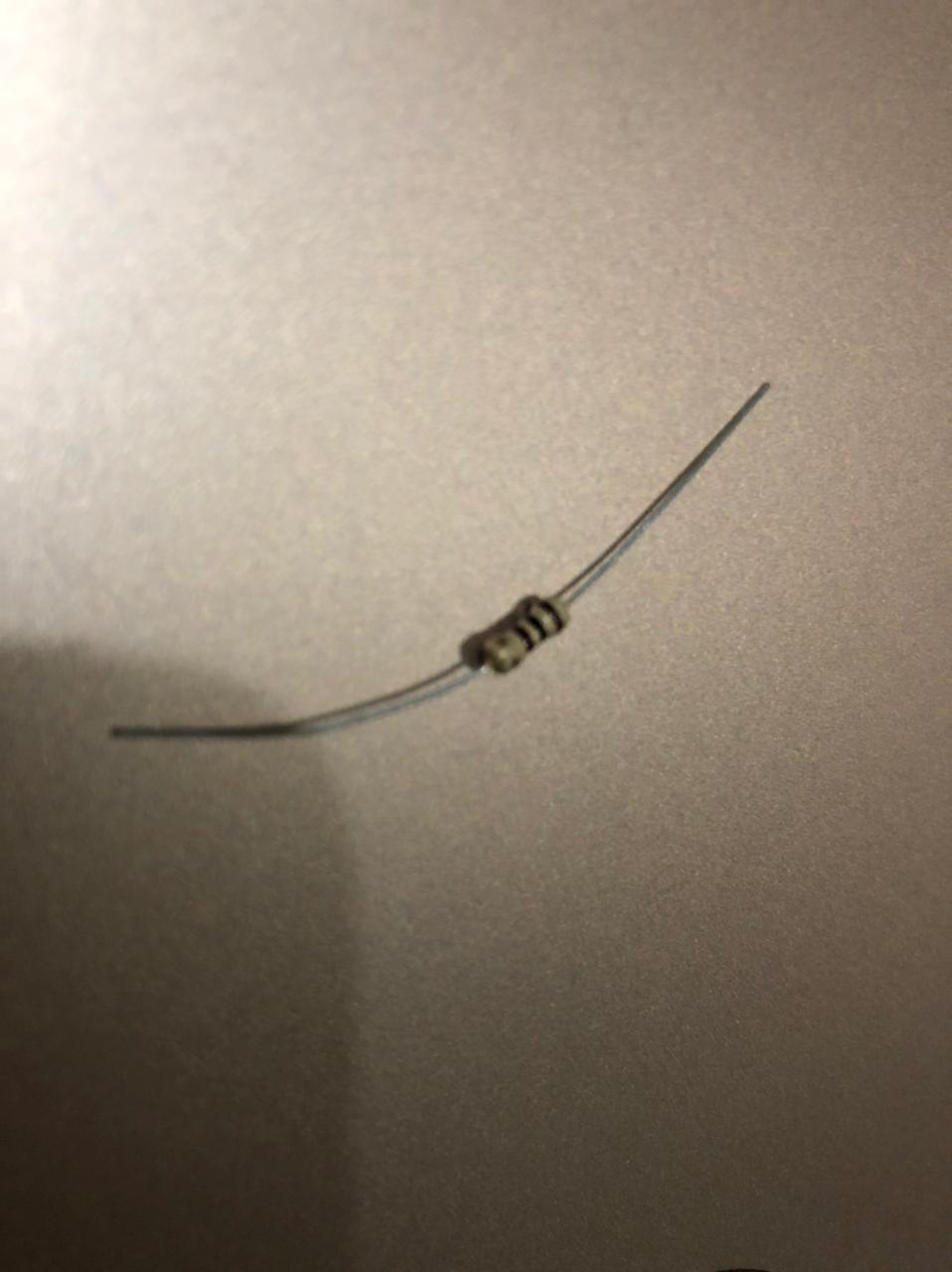
- 3 Resistors of 50 Ω each
- Connecting wires
- Jumping wires (Male to male)
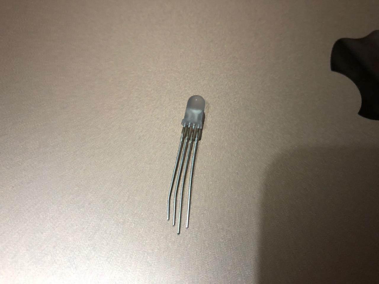
- RGB LEDs
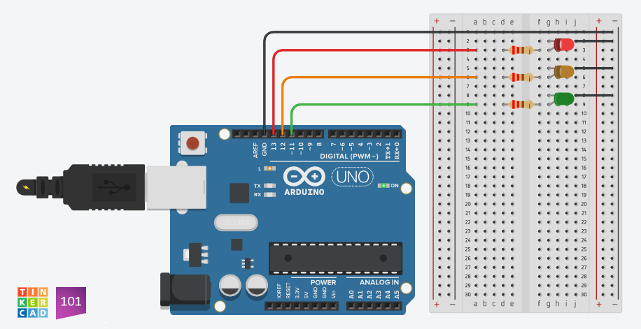
Assembling
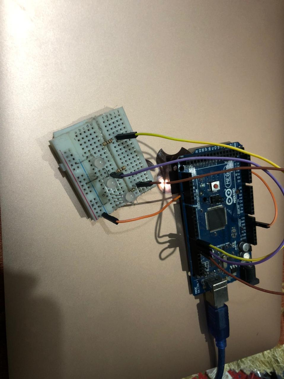
Connect the anode of each LED to digital pins in the Arduino. In my project, I connected the red color anode to pin 8 and the green color anode to pin 10. To produce the yellow light effect, I mixed the red and green anode with the help of connecting wires and connected it to pin 9. After that, I connected the cathodes to the Arduino's ground. In the end, I connected the resistors to the breadboard.
Start Coding
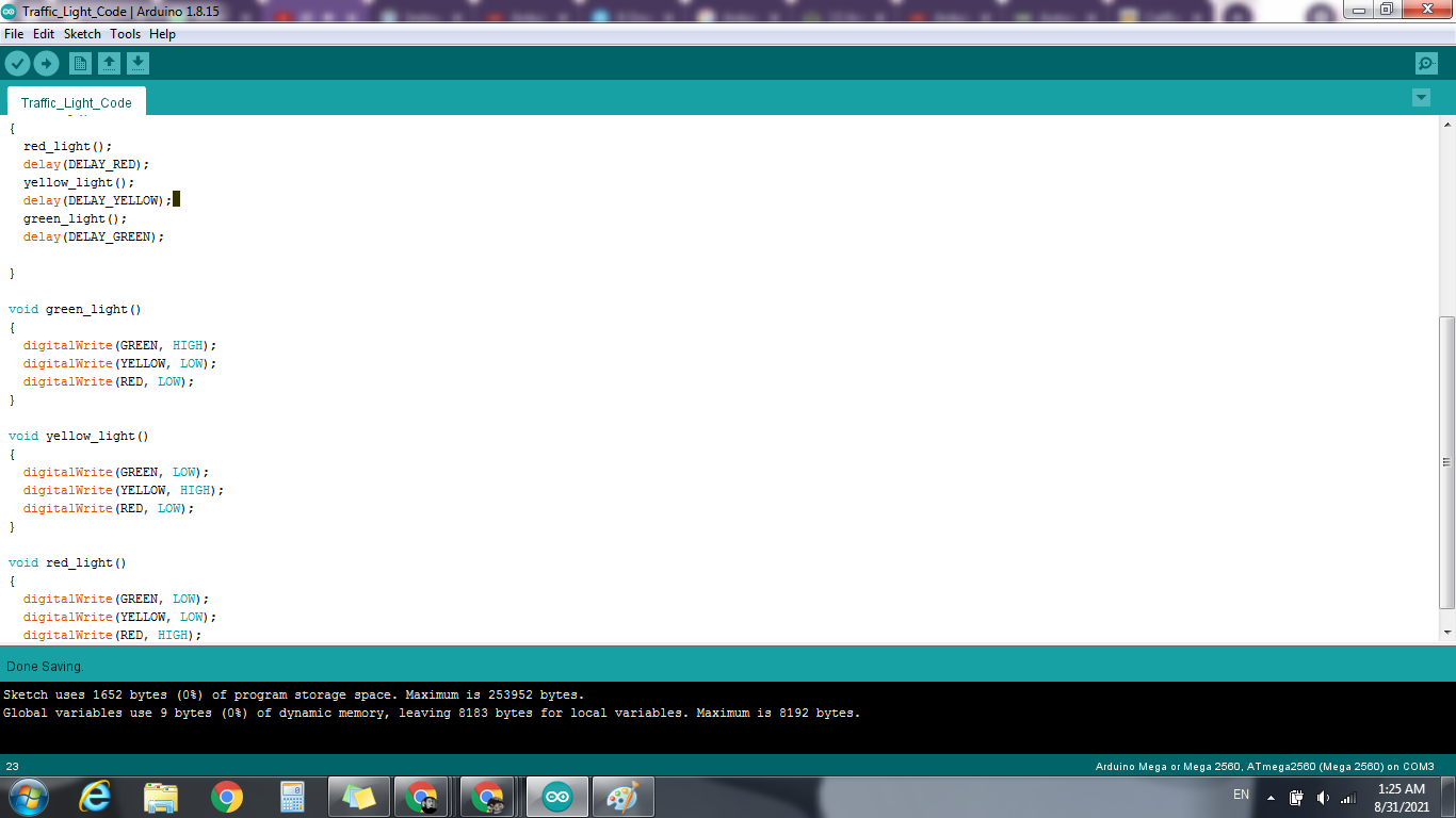
Here is the last step. Now you just have to code the program and run them. This is the code I ran on the Arduino IDE.
// variables
int GREEN = 10;
int YELLOW = 9;
int RED = 8;
int DELAY_GREEN = 5000;
int DELAY_YELLOW = 2000;
int DELAY_RED = 5000;
// basic functions void setup()
{
pinMode(GREEN, OUTPUT);
pinMode(YELLOW, OUTPUT);
pinMode(RED, OUTPUT);
}
void loop()
{
red_light();
delay(DELAY_RED);
yellow_light();
delay(DELAY_YELLOW);
green_light();
delay(DELAY_GREEN);
}
void green_light()
{
digitalWrite(GREEN, HIGH);
digitalWrite(YELLOW, LOW);
digitalWrite(RED, LOW);
}
void yellow_light()
{
digitalWrite(GREEN, LOW);
digitalWrite(YELLOW, HIGH);
digitalWrite(RED, LOW);
}
void red_light()
{
digitalWrite(GREEN, LOW);
digitalWrite(YELLOW, LOW);
digitalWrite(RED, HIGH);
}
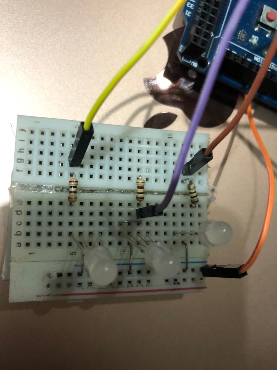
Running the Program
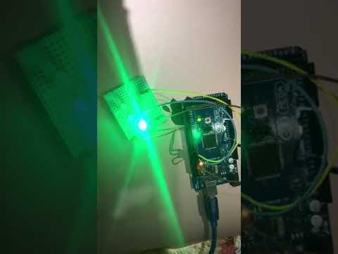
This should be the end result of the project.