Track&trace for Small Shops
by marcoVDG in Circuits > Raspberry Pi
1186 Views, 9 Favorites, 0 Comments
Track&trace for Small Shops
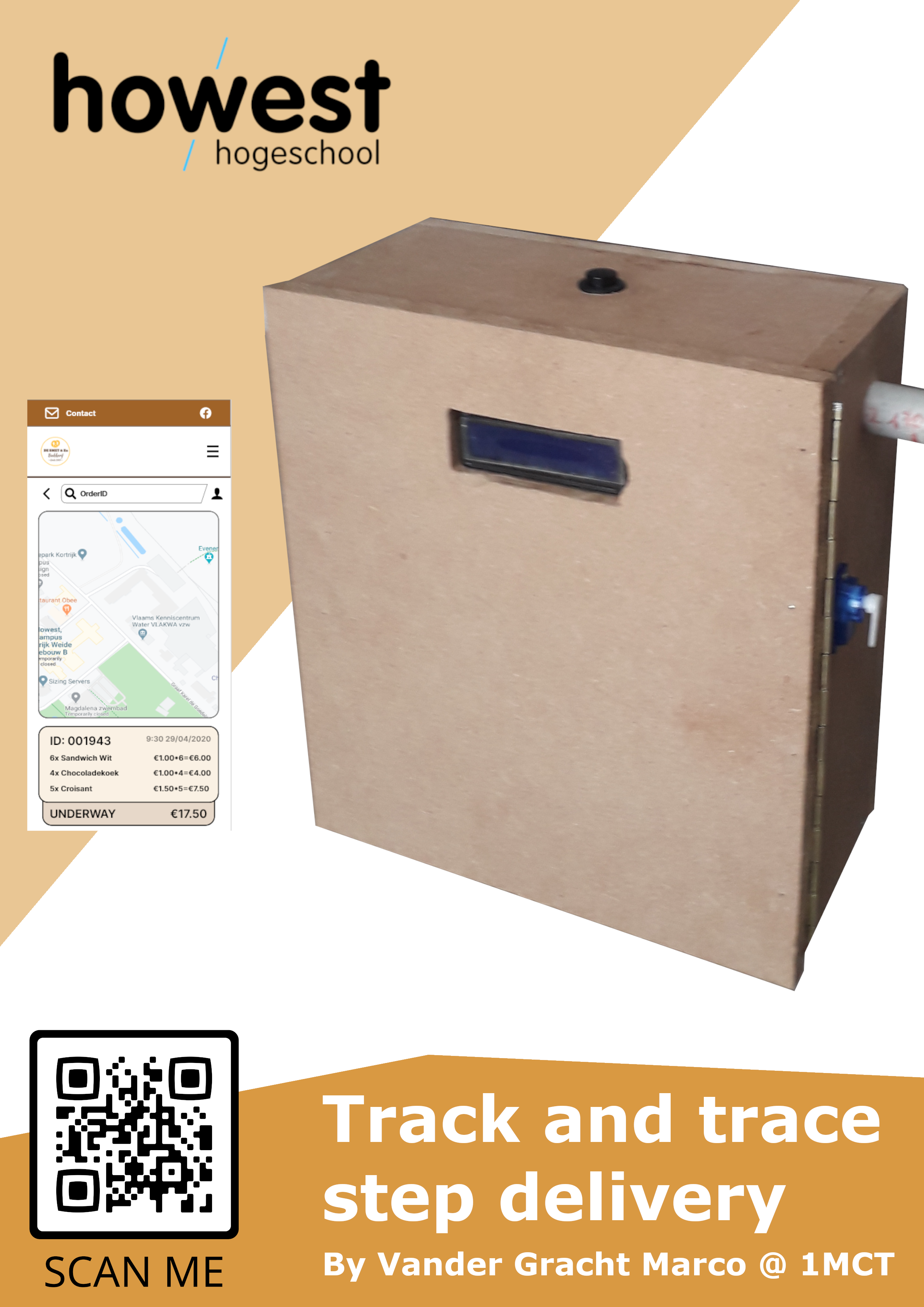
This is a system that is made for small shops that is supposed to mount onto e-bikes or e-scooters for short range deliveries, for example a bakery that wants to deliver pastries.
What does Track and Trace mean?
Track and trace is a system used by carriers or courier companies to record the movement of parcels or items during transportation. At every processing location, the goods are identified and data relay to the central processing system. This data is then used to give status/update of the goods location to the shippers.
The system we will make will also show the route taken and the amount of shocks and bumps recieved.
This instructables also assumes you have a basic knowledge of a raspberry pi, python and mysql.
note: this was made for a school project, thus due to the time constraint there is a lot of room for improvement
Supplies
-Raspberry Pi 4 model B
-Raspberry PI T-cobbler
-4x 3,7V Li-ion batteries
-2x double Battery holder
-DC Buck Step-down Converter 5v
-2x big orange led's
-on/off/on switch
-button
-adafruit ultimate gps v3
-mpu6050
-16x2 lcd display
-servo motor
Powering the Circuit and Pi
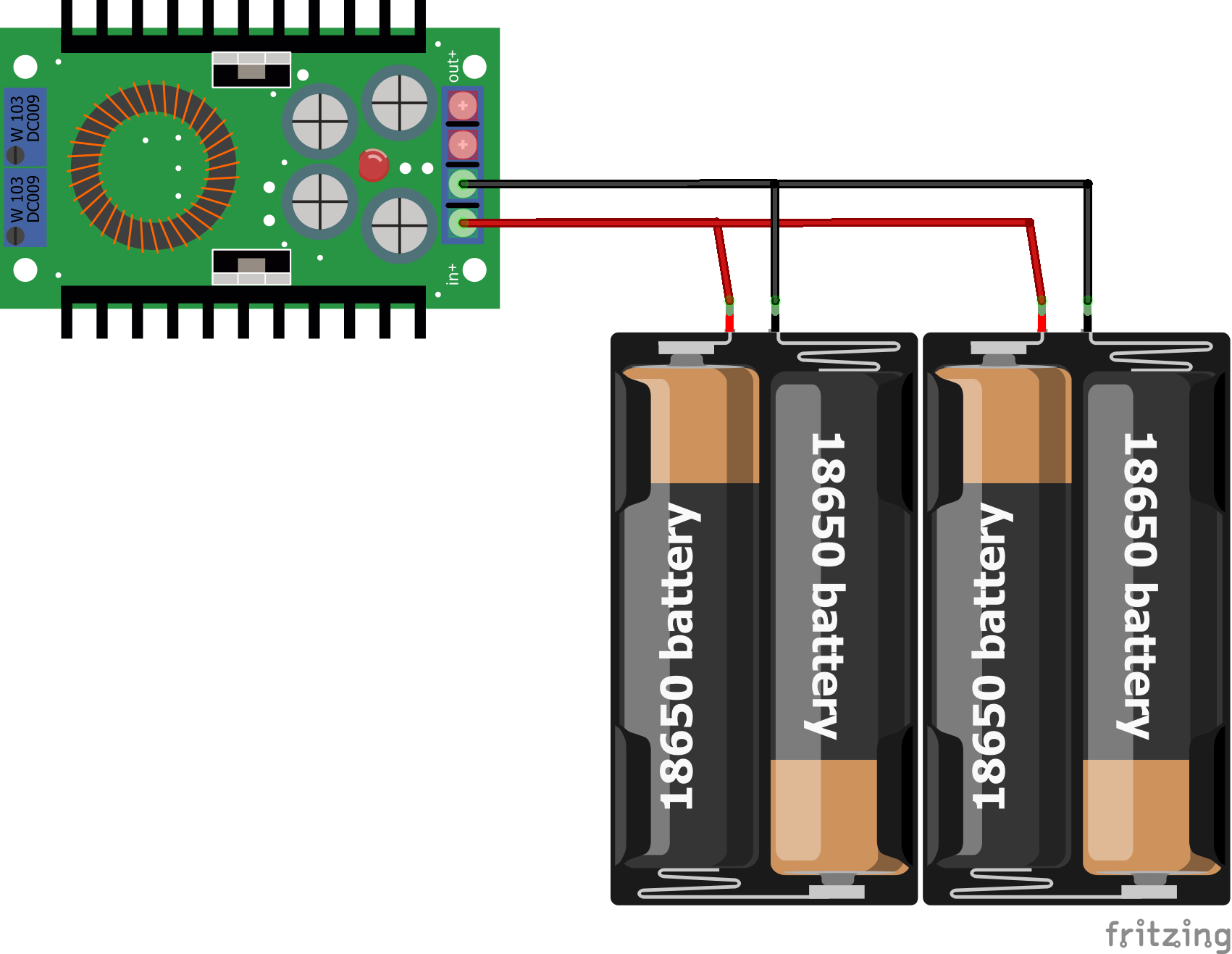
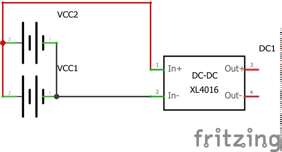
When it comes to powering the circuit pi with a battery you have a few options on how to do it.
You could use a powerbank and power the pi via USB,
maybe you are mounting the device on a e-bike or e-scooter that has a USB port,
perhaps you have a 5V phone battery lying around waiting to be used
or you could use 2 sets of 3.7V battery's in parallel with a step down convertor like shown in the pictures
Anything is fine as long as it can provide a continuous 5V and has a lifetime you are happy with.
The MPU6050
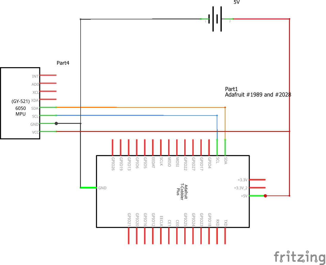
Introduction
MPU6050 sensor module is an integrated 6-axis Motion tracking device.
- It has a 3-axis Gyroscope, 3-axis Accelerometer, Digital Motion Processor and a Temperature sensor, all in a single IC.
- Various parameters can be found by reading values from addresses of certain registers using I2C communication.Gyroscope and accelerometer reading along X, Y and Z axes are available in 2’s complement form.
- Gyroscope readings are in degrees per second (dps) unit; Accelerometer readings are in g unit.
Enabling I2C
When using a MPU6050 with a Raspberry Pi, we should ensure that I2C protocol on the Raspberry Pi is turned on.
To do this open the pi's terminal thru putty or other softaware and do the following:
- type in "sudo raspi-config"
- Select Interfacing Configurations
- In Interfacing option, Select "I2C"
- Enable I2C configuration
- Select Yes when it asks to Reboot.
Now, we can test/scan for any I2C device connected to our Raspberry Pi board by installing i2c tools. We can get i2c tools by using apt package manager. Use following command in Raspberry Pi terminal.
"sudo apt-get install -y i2c-tools"
Now connect any I2C based device to the user-mode port and scan that port using following command,
"sudo i2cdetect -y 1"
Then it will respond with device address.
If no adress is returned make sure the MPU6050 is properly connected and try again
Making it work
now that we are sure i2c is enabled and the pi can reach the MPU6050 we are going to install a library using the
"sudo pip3 install adafruit-circuitpython-mpu6050" command.
if we make a python test file and use the following code we can see if its working:
import time
import board
import busi
oimport adafruit_mpu6050
i2c = busio.I2C(board.SCL, board.SDA)
mpu = adafruit_mpu6050.MPU6050(i2c)
while True:
print("Acceleration: X:%.2f, Y: %.2f, Z: %.2f m/s^2" % (mpu.acceleration))
print("Gyro X:%.2f, Y: %.2f, Z: %.2f degrees/s" % (mpu.gyro))
print("Temperature: %.2f C" % mpu.temperature)
print("")
time.sleep(1)
when we now want the acceleration in the X/Y/Z-axis we can use the following:
accelX = mpu.acceleration[0]
accelY = mpu.acceleration[1]
accelZ = mpu.acceleration[2]
combining this with a simple if statement in a constant loop we can count the amount of shocks on a trip
The Adafruit Ultimate Breakout GPS
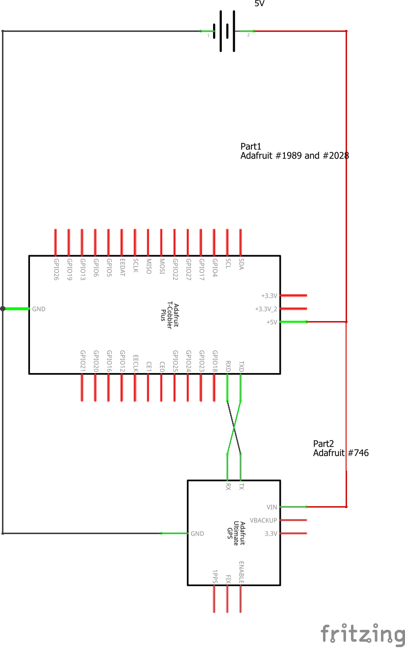
Introduction
The breakout is built around the MTK3339 chipset, a no-nonsense, high-quality GPS module that can track up to 22 satellites on 66 channels, has an excellent high-sensitivity receiver (-165 dB tracking!), and a built in antenna. It can do up to 10 location updates a second for high speed, high sensitivity logging or tracking. Power usage is incredibly low, only 20 mA during navigation.
The board comes with: a ultra-low dropout 3.3V regulator so you can power it with 3.3-5VDC in, 5V level safe inputs,
The LED blinks at about 1Hz while it's searching for satellites and blinks once every 15 seconds when a fix is found to conserve power.
Testing the gps with arduino
If you have acces to a arduino its a good idea to test the module with it.
Connect VIN to +5V
Connect GND to Ground
Connect GPS RX (data into GPS) to Digital 0
Connect GPS TX (data out from GPS) to Digital 1
Simply run a blank arduino code and open the serial monitor on 9600 baud.
If you get gps data your gps module works.
Note: if your module doesnt get a fix try putting it out a window or outside on a terrace
Making it work
Start of installing the adafruit gps library using the "sudo pip3 install adafruit-circuitpython-gps" command.
Now we can use the following python code to see if we can make it work:
import time
import board import busio
import adafruit_gps
import serial uart = serial.Serial("/dev/ttyS0", baudrate=9600, timeout=10)
gps = adafruit_gps.GPS(uart, debug=False)
gps.send_command(b'PMTK314,0,1,0,1,0,0,0,0,0,0,0,0,0,0,0,0,0,0,0')
gps.send_command(b'PMTK220,1000')
while True:
gps.update()
while not gps.has_fix:
print(gps.nmea_sentence)
print('Waiting for fix...')
gps.update()
time.sleep(1)
continue
print('=' * 40) # Print a separator line.
print('Latitude: {0:.6f} degrees'.format(gps.latitude))
print('Longitude: {0:.6f} degrees'.format(gps.longitude))
print("Fix quality: {}".format(gps.fix_quality))
# Some attributes beyond latitude, longitude and timestamp are optional
# and might not be present. Check if they're None before trying to use!
if gps.satellites is not None:
print("# satellites: {}".format(gps.satellites))
if gps.altitude_m is not None:
print("Altitude: {} meters".format(gps.altitude_m))
if gps.speed_knots is not None:
print("Speed: {} knots".format(gps.speed_knots))
if gps.track_angle_deg is not None:
print("Track angle: {} degrees".format(gps.track_angle_deg))
if gps.horizontal_dilution is not None:
print("Horizontal dilution: {}".format(gps.horizontal_dilution))
if gps.height_geoid is not None:
print("Height geo ID: {} meters".format(gps.height_geoid))
time.sleep(1)
The 16x2 LCD
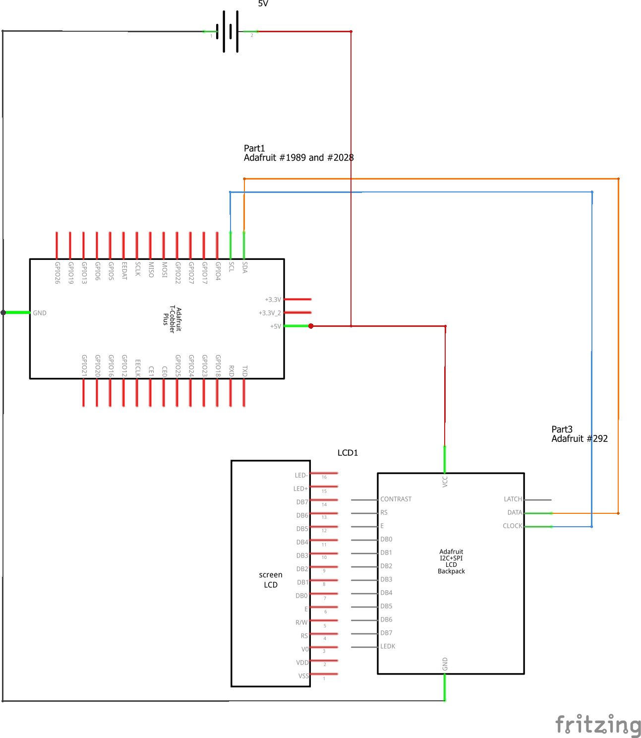
Introduction
LCD modules are very commonly used in most embedded projects, the reason being its cheap price, availability and programmer friendly. Most of us would have come across these displays in our day to day life, either at PCO’s or calculators.
16×2 LCD is named so because; it has 16 Columns and 2 Rows. There are a lot of combinations available like, 8×1, 8×2, 10×2, 16×1, etc. but the most used one is the 16×2 LCD. So, it will have (16×2=32) 32 characters in total and each character will be made of 5×8 Pixel Dots.
Installing smbus
The System Management Bus (SMBus) is more or less a derivative of the I2C bus. The standard has been developed by Intel and is now maintained by the SBS Forum.
The main application of the SMBus is to monitor critical parameters on PC motherboards and in embedded systems. For example there a lot of supply voltage monitor, temperature monitor, and fan monitor/control ICs with a SMBus interface available.
The library we will use requires smbus to be installed aswell.
To install smbus on the rpi use the "sudo apt install python3-smbus" command.
Making it work
first of install the RPLCD library using the "sudo pip3 install RPLCD" command.
now we test the lcd by displaying the ip using the following code:
from RPLCD.i2c import CharLCD
import socket
def get_ip_address():
ip_address = ''
s = socket.socket(socket.AF_INET, socket.SOCK_DGRAM)
s.connect(("8.8.8.8", 80))
ip_address = s.getsockname()[0]
s.close()
return ip_address
lcd = CharLCD('PCF8574', 0x27)
lcd.write_string('IP adress:\r\n'+str(get_ip_address()))
Servo, Leds, Button and Switch
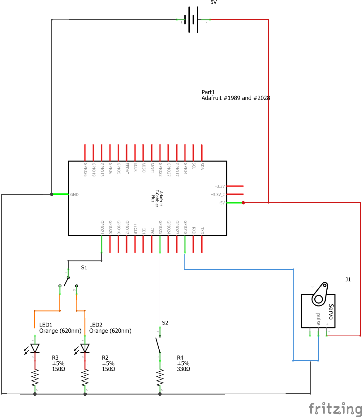
Introduction
A servo motor is a rotary actuator or motor that allows for a precise control in terms of angular position, acceleration and velocity, capabilities that a regular motor does not have. It makes use of a regular motor and pairs it with a sensor for position feedback. The controller is the most sophisticated part of the servo motor, as it is specifically designed for the purpose.
LED short for light-emitting diode. An electronic semiconductor device that emits light when an electric current passes through it. They are considerably more efficient than incandescent bulbs, and rarely burn out. LEDs are used in many applications such as flat-screen video displays, and increasingly as general sources of light.
A push-button or simply button is a simple switch mechanism to control some aspect of a machine or a process. Buttons are typically made out of hard material, usually plastic or metal.
A on/off/on switch has 3 positions where the middle one is the off state these types are mostly used for simple motor control where you have a forward, off and reverse state.
Making it work: the servo
The servo uses a PWM signal to determine what angle it needs to be at luckly for us GPIO has this feature built in.
Therefore we can simply use the following code to control the servo:
import RPi.GPIO as GPIO
import time
servo_pin = 18
duty_cycle = 7.5
GPIO.setmode(GPIO.BCM)
GPIO.setup(servo_pin, GPIO.OUT)
pwm_servo = GPIO.PWM(servo_pin, 50) pwm_servo.start(duty_cycle)
while True:
duty_cycle = float(input("Enter Duty Cycle (Left = 5 to Right = 10):"))
pwm_servo.ChangeDutyCycle(duty_cycle)
Making it work: the led and switch
Due to the way we wired the led's and the switch we don't need to control or read the leds and switch itself.
We simply send pulses to the button witch will in turn route the signal to the led we want.
Making it work: the button
For the button we shall make our own simple class this way we easily see when its pressed without having to add a event detect to it each time we use it.
we will make the file classbutton.py using the following code:
from RPi import GPIO
class Button:
def __init__(self, pin, bouncetime=200):
self.pin = pin
self.bouncetime = bouncetime
GPIO.setmode(GPIO.BCM)
GPIO.setup(pin, GPIO.IN, GPIO.PUD_UP)
@property
def pressed(self):
ingedrukt = GPIO.input(self.pin)
return not ingedrukt
def on_press(self, call_method):
GPIO.add_event_detect(self.pin, GPIO.FALLING, call_method, bouncetime=self.bouncetime)
def on_release(self, call_method):
GPIO.add_event_detect(self.pin, GPIO.RISING, call_method, bouncetime=self.bouncetime)
The Full Circuit
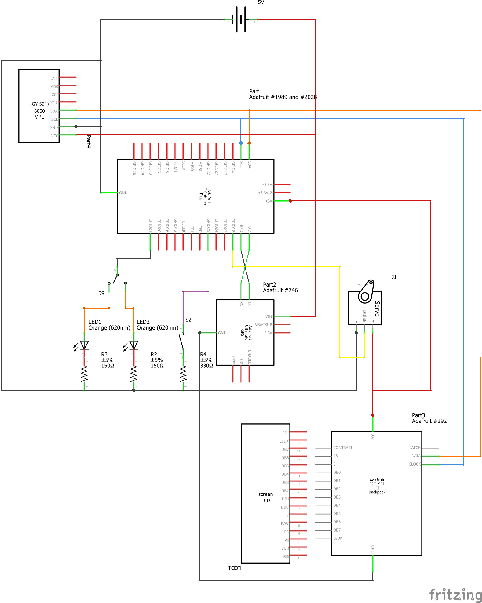
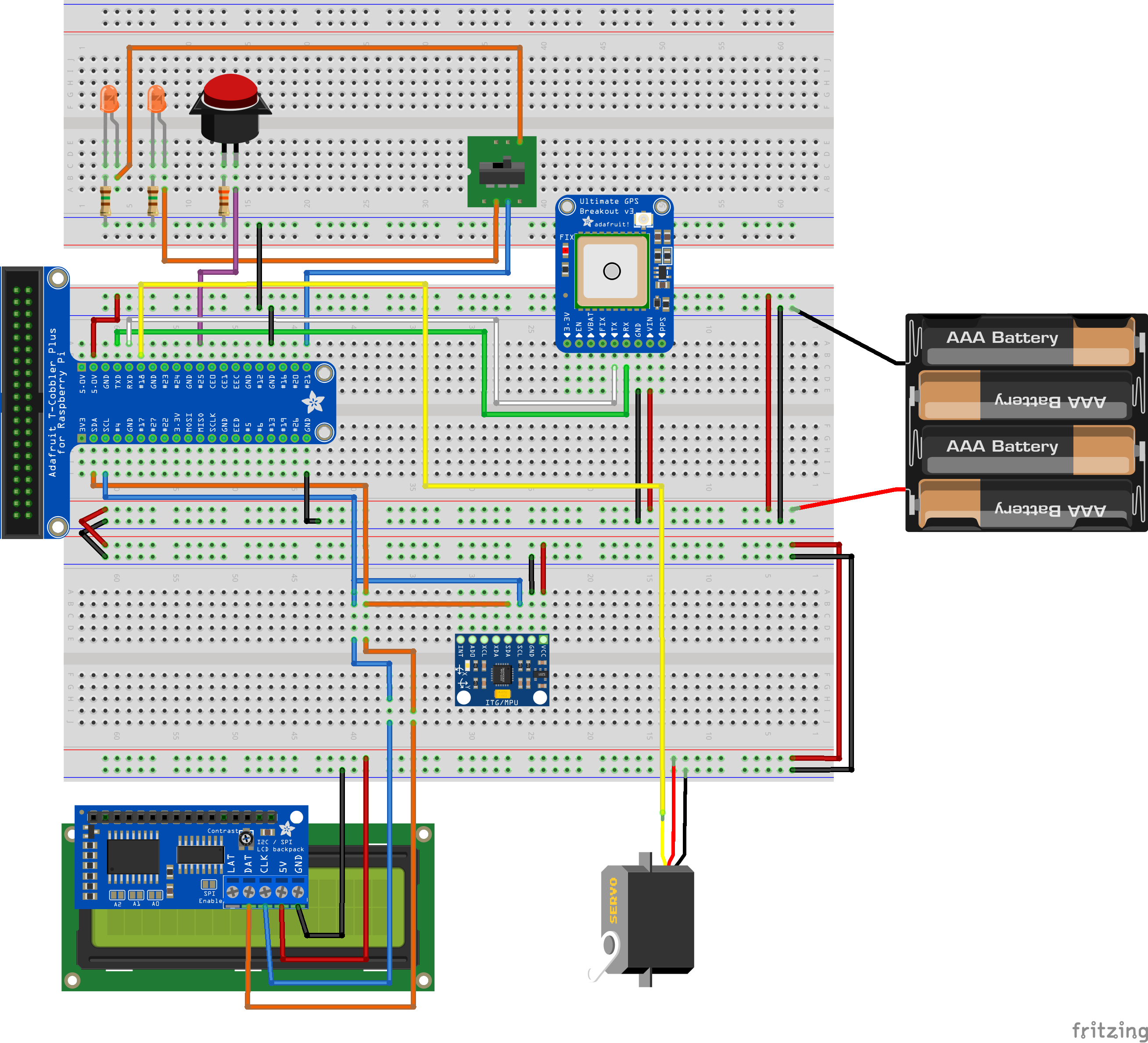
Now that we have gone over all the components its time to combine all of them.
While the pictures show the components show everything on the breadboard itself its better to have the lcd, adafruit GPS and button connected using female to male wires
Only have the t-cobbler and the mpu6050 on a breadboard.
When it comes to the led's and the switch use longer wires to make sure you can reach the blinker bars and steering bar.
The Code
To keep this instructable clean i have provided a github repository with both the backend and frontend files.
simply put the files in the frontend folder in the /var/www/html folder
and the files in the backend folder in a folder in the /home/[username]/[foldername] folder
The Database
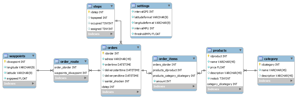
Because of the way this system is set up there is a simple webshop set up using a list of products in a database,
furthermore we have all the way points and orders saved here.
A create script can be found on the github repository linked in the next step
The Case
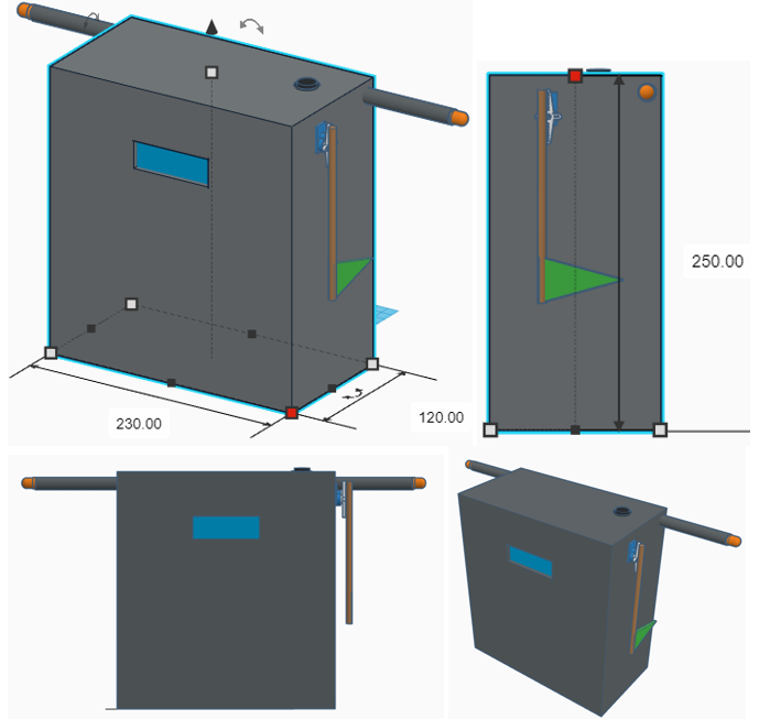
Once we know the electronics work we can stuff them into a box.
You can take some creative liberty with this.
Before constructing it simply grab a cardboard box you don't need anymore like a empty cereal box for example and cut it, tape it and fold it till you have something you like.
Measure and draw your case on a piece of paper and make it from a more sturdy material like wood,
or if thats not your thing 3d print it.
Just make sure all the electronics fit inside and you have holes for the button, the wire going to the switch, the led's and the lcd.
Once you have made your case its just a matter of finding a way of mounting it on your bike or scooter