Touch Cam - a Raspberry Pi Camera
by Mukesh_Sankhla in Circuits > Raspberry Pi
32367 Views, 193 Favorites, 0 Comments
Touch Cam - a Raspberry Pi Camera
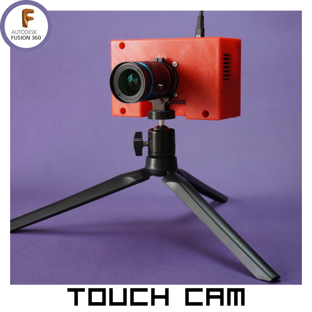
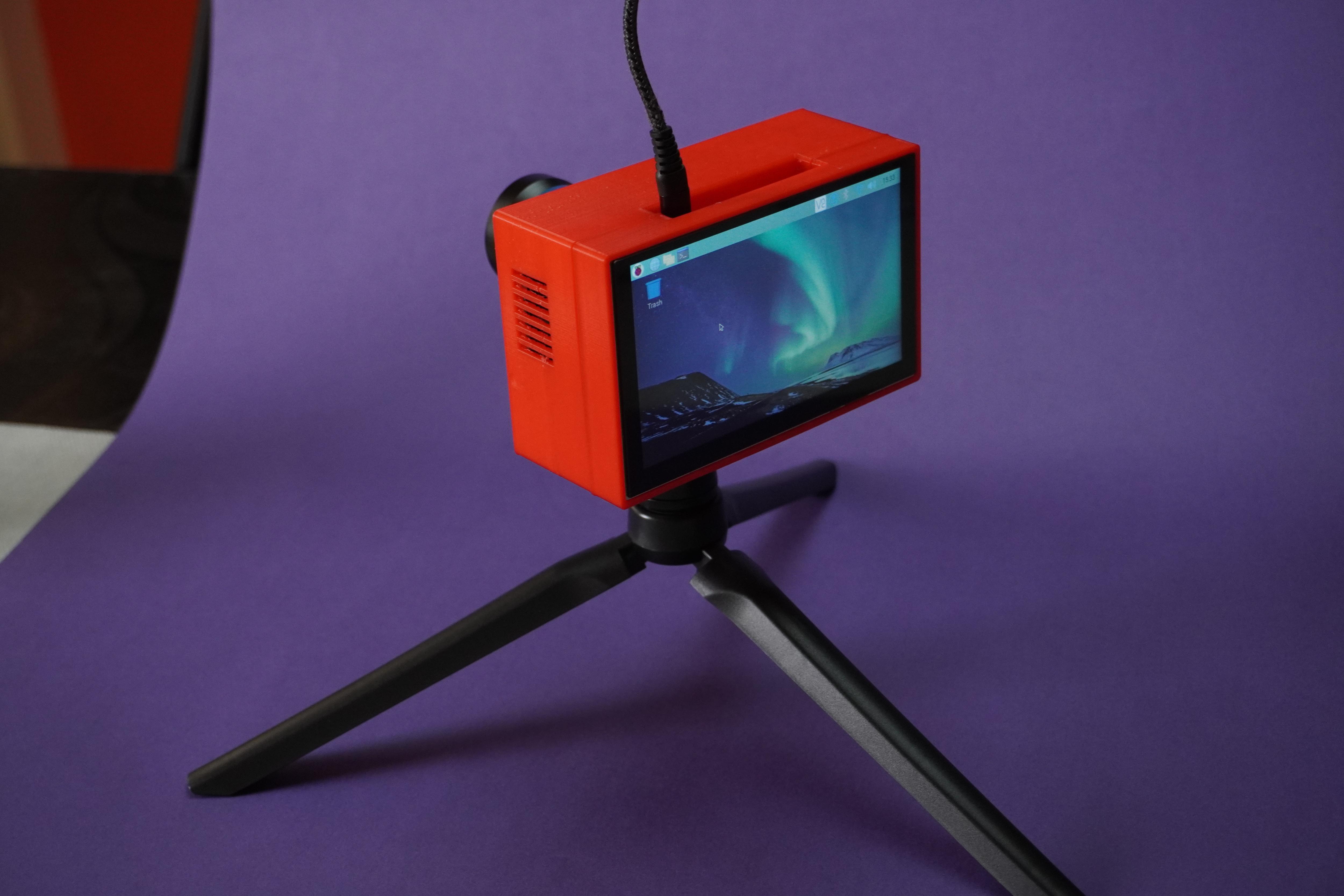
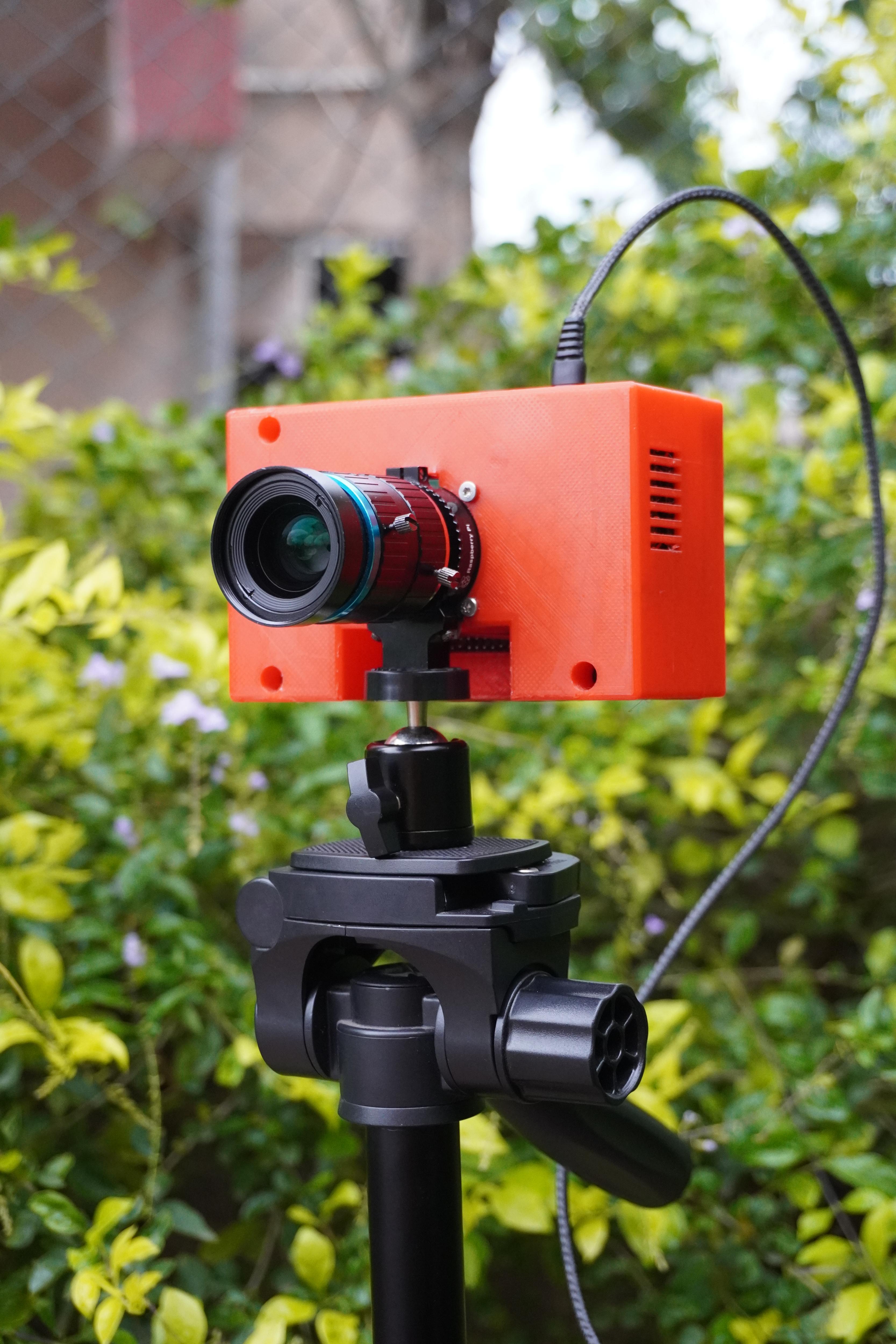
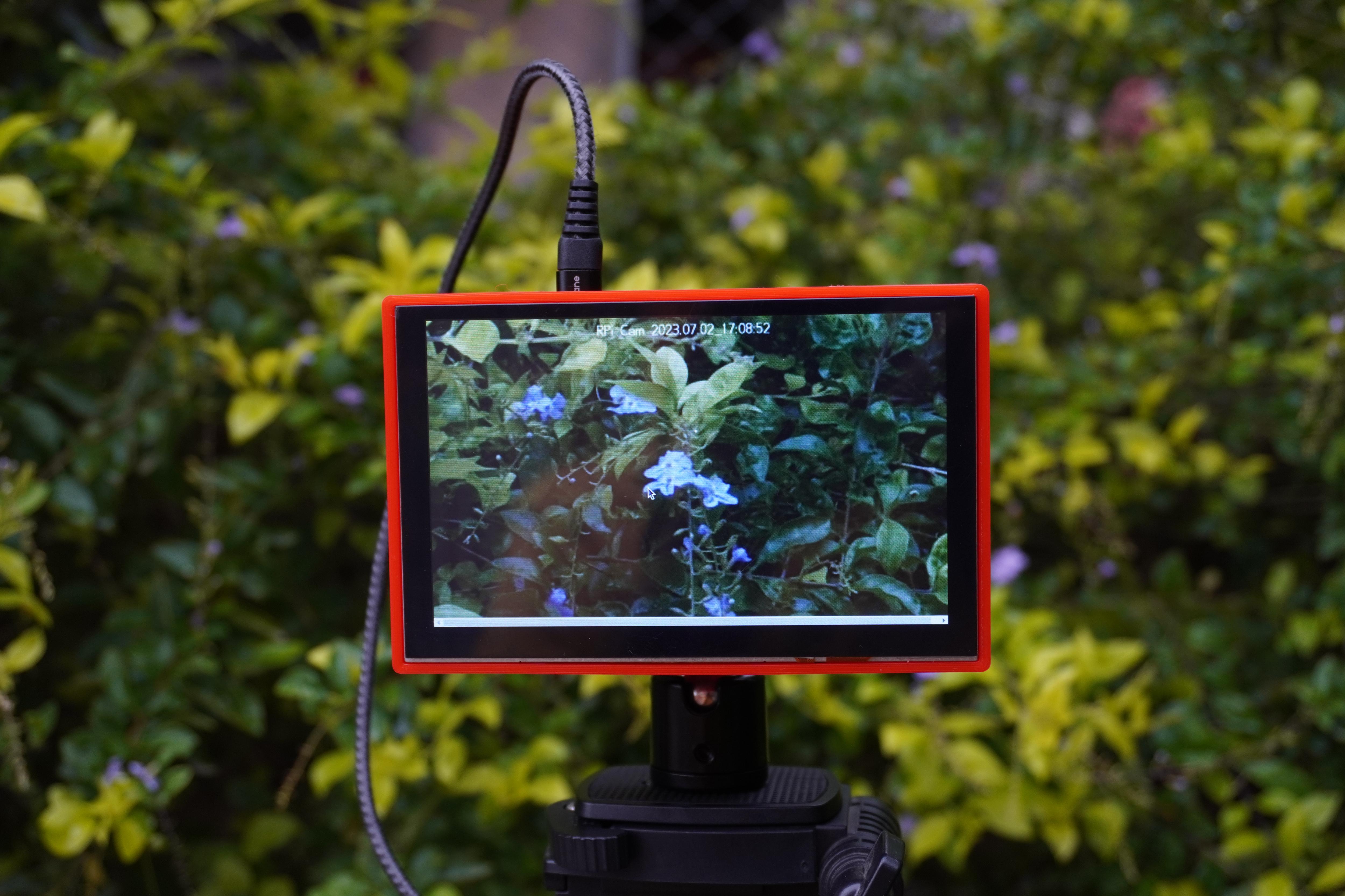
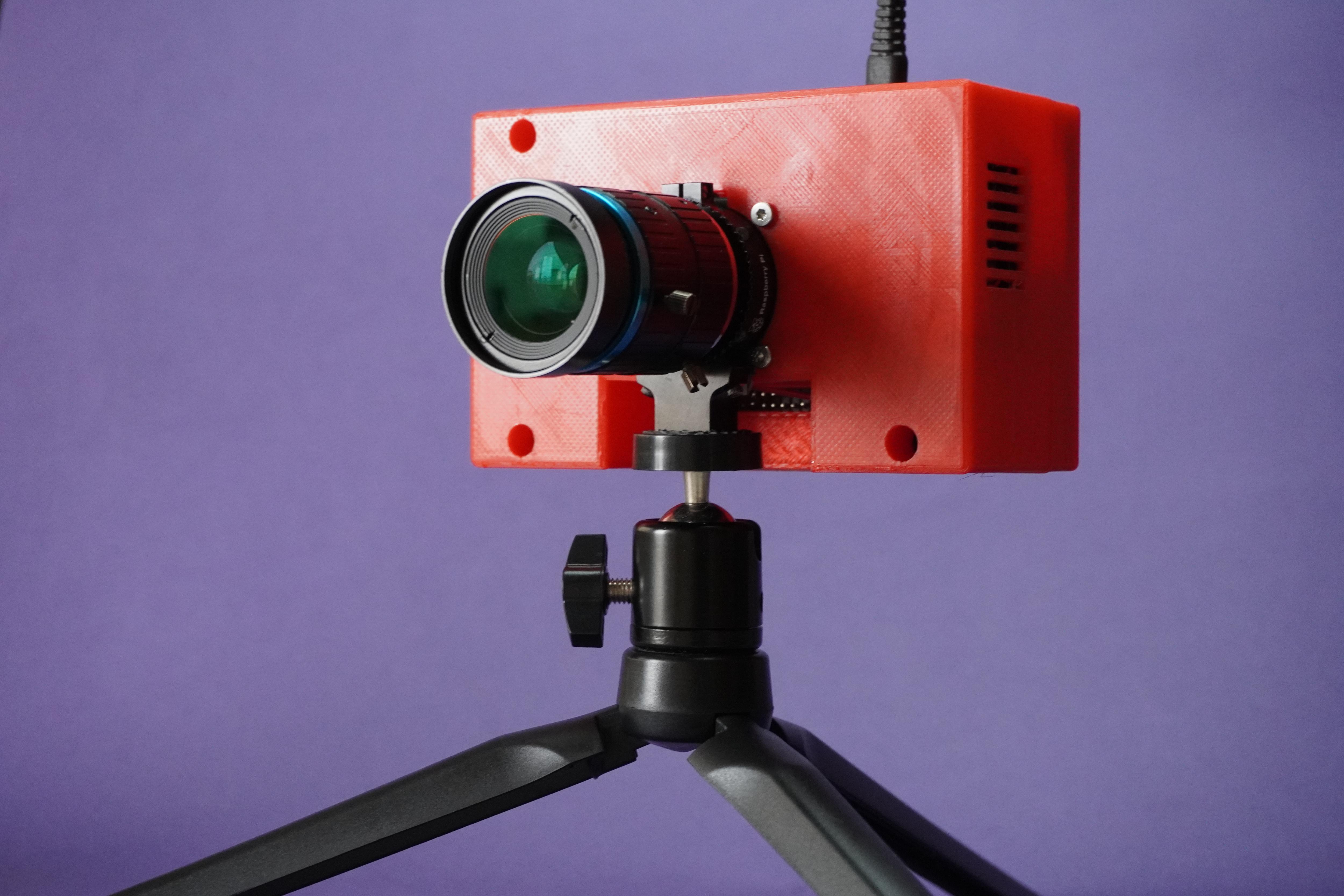
The Touch Cam is a redesigned and enhanced version of the Pi Cam - A Raspberry Pi Desktop Camera Server, integrating a touch display and touch sensor for an intuitive and interactive user experience. This project combines the power of Raspberry Pi with a custom CAD redesign and an innovative touch interface, allowing users to conveniently capture photos, videos, and time-lapse sequences.
Key Features:
- Touch Display: The Touch Cam features a high-resolution touch display, providing a visual interface for camera controls, image previews, and video playback. With the touch display, users can easily navigate through menus, and view real-time images and videos.
- Touch Sensor: A touch sensor has been incorporated into the design, enabling seamless operation for capturing photos and starting time-lapse sequences. By simply tapping the touch sensor, users can initiate the desired camera function, whether it's capturing a single photo or starting a time-lapse sequence.
- Raspberry Pi Desktop Camera Server: The project leverages the computational capabilities of Raspberry Pi to serve as a versatile camera server. The Touch Cam provides a web-based interface accessible from any device connected to the same network, allowing users to remotely control and access the camera's functionalities for capturing photos, recording videos, and creating time-lapse sequences.
- Cooling System: The Touch Cam is equipped with a 5V cooling fan and heatsinks to ensure efficient temperature regulation. The cooling system prevents the Raspberry Pi from overheating during extended usage, providing reliable performance and stability even in demanding situations.
- Custom CAD Redesign: The custom CAD redesign not only enhances functionality but also ensures a sleek and functional design, accommodating the touch display, touch sensor, cooling fan, heatsinks, Raspberry Pi HQ camera module and Raspberry Pi within a compact and user-friendly camera enclosure.
- Easy Setup and Configuration: Setting up the Touch Cam is straightforward, requiring minimal technical expertise. With clear documentation and step-by-step instructions, users can quickly assemble the hardware components, install the necessary software, and start capturing stunning photos and creating time-lapse sequences.
The Touch Cam showcases my CAD design skills and expertise as a bachelor's computer science student at Guru Nanak Dev Engineering Colleg, Bidar, India. Having started using Fusion 360 in 2018 when I was in secondary school, I have been able to bring my imagination to reality using Fusion 360 and 3D printing and made many projects in past few years.
In this tutorial, I will provide a detailed explanation of the designing process using Fusion 360 for the Touch Cam project. Fusion 360 is a powerful CAD (Computer-Aided Design) software that enables users to create complex 3D models and designs. By following these steps, you will be able to harness the full potential of Fusion 360 to design and visualize your own projects.
Note: Feel free to further customize and expand the project description based on any additional features or functionalities you incorporated into your version of the Touch Cam or any other relevant details you would like to include.
Supplies
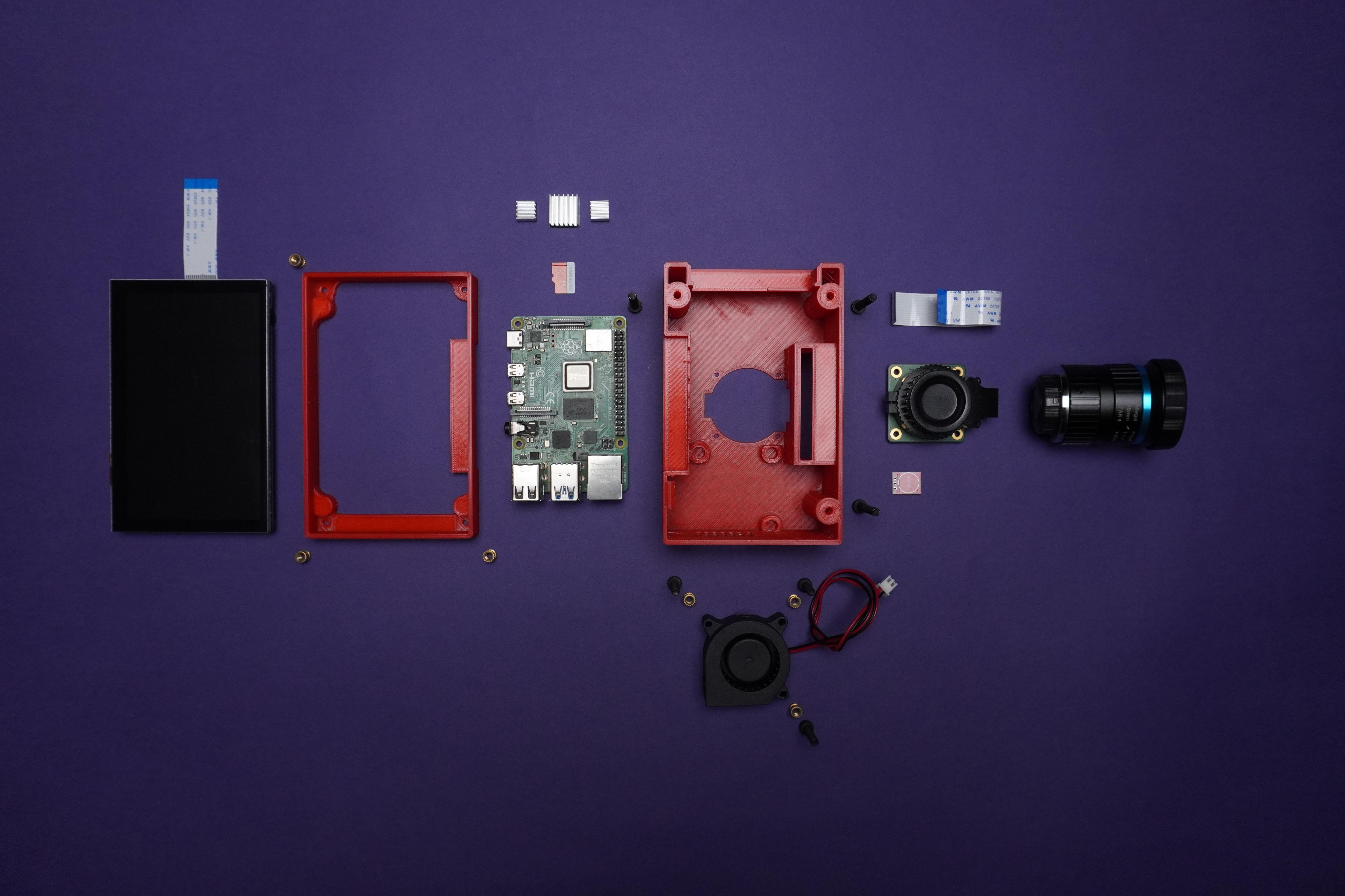
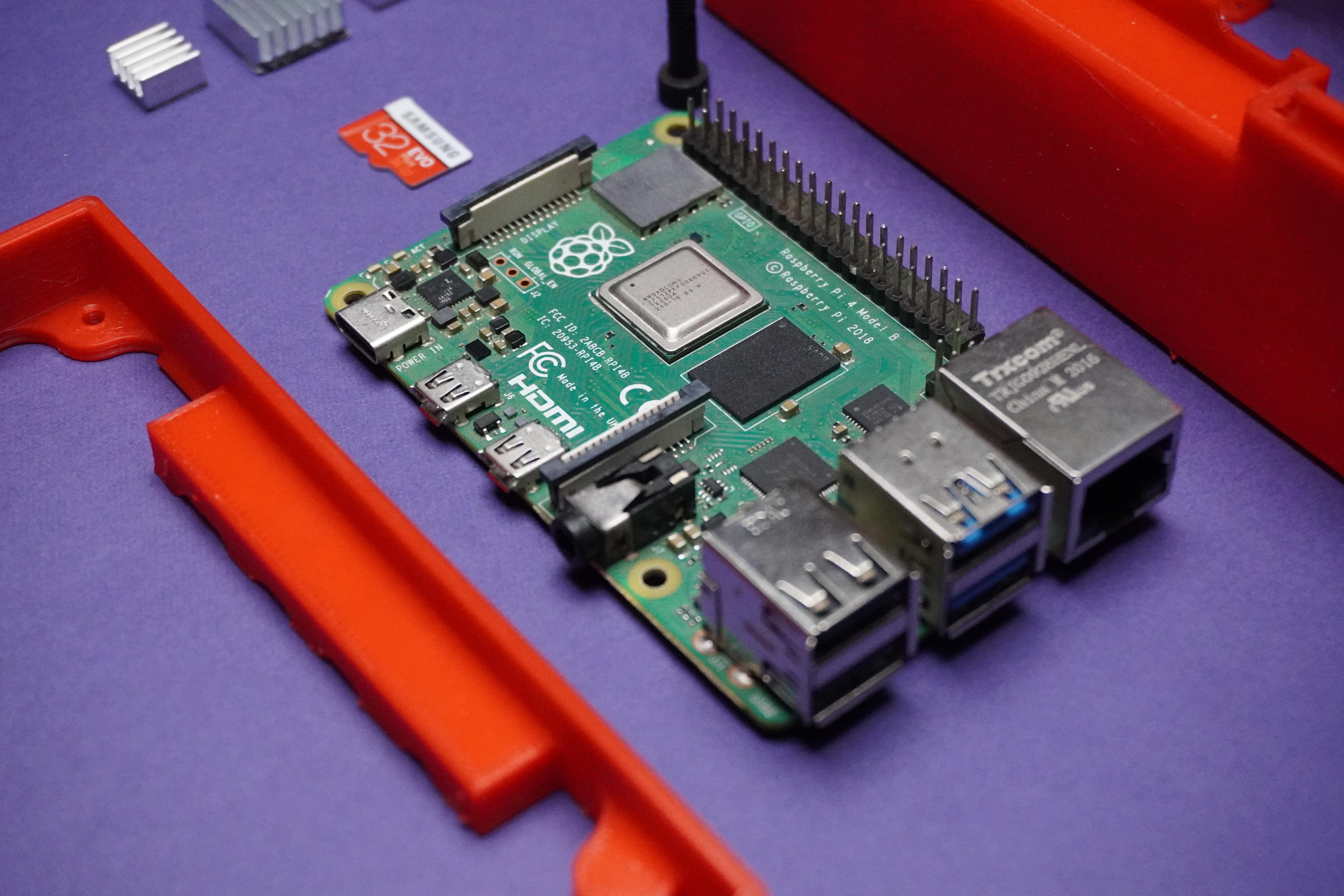
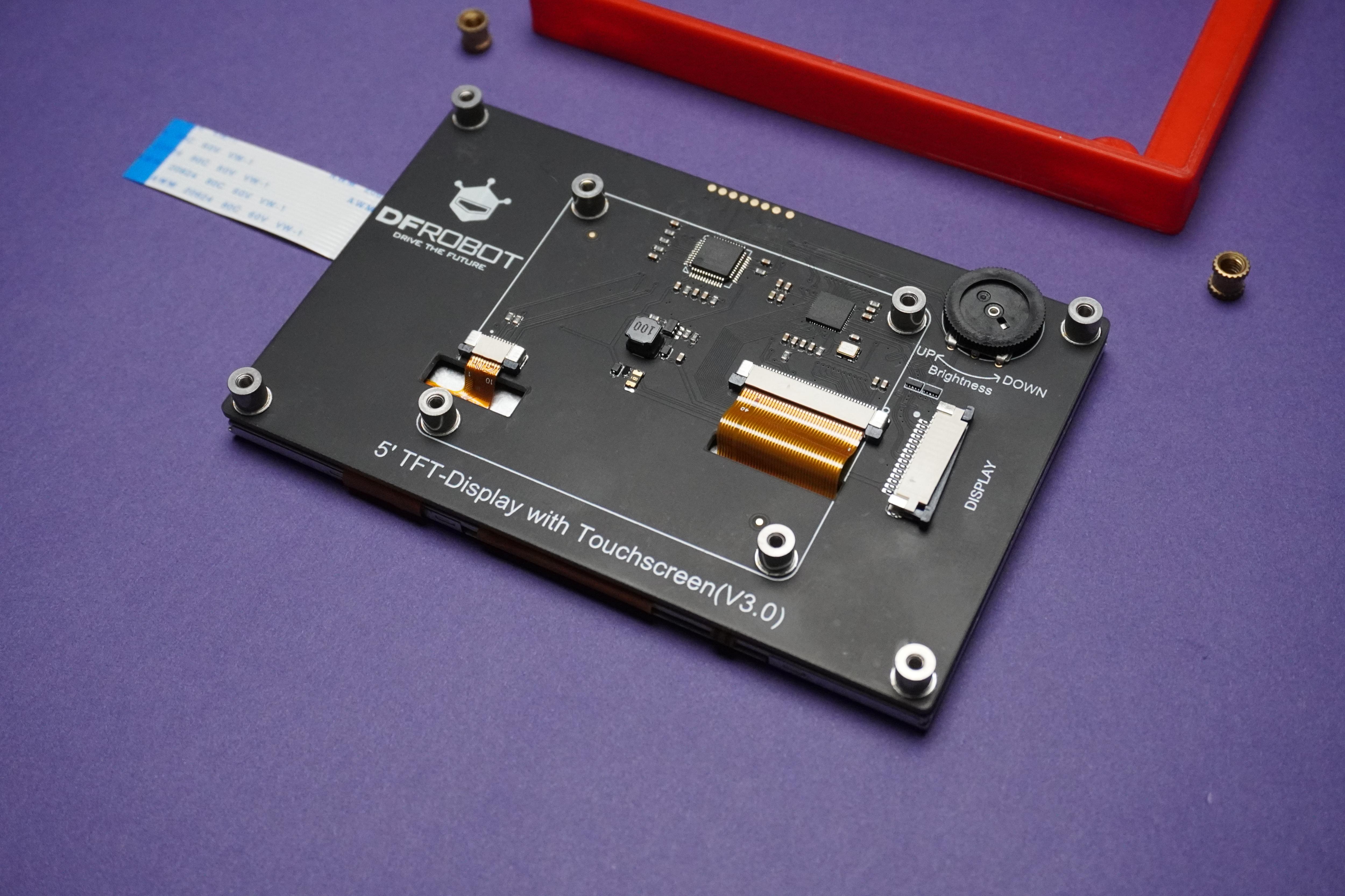
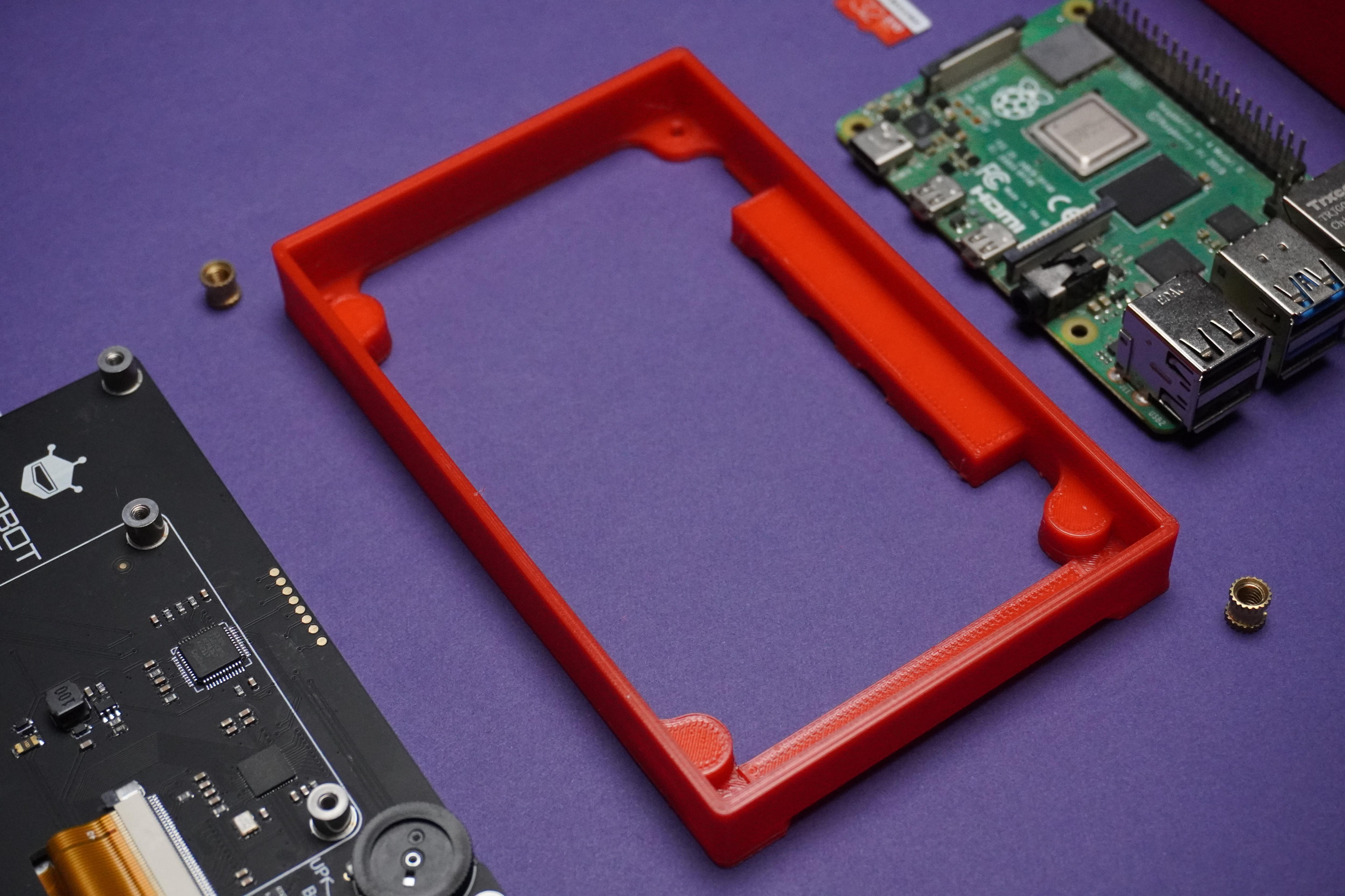
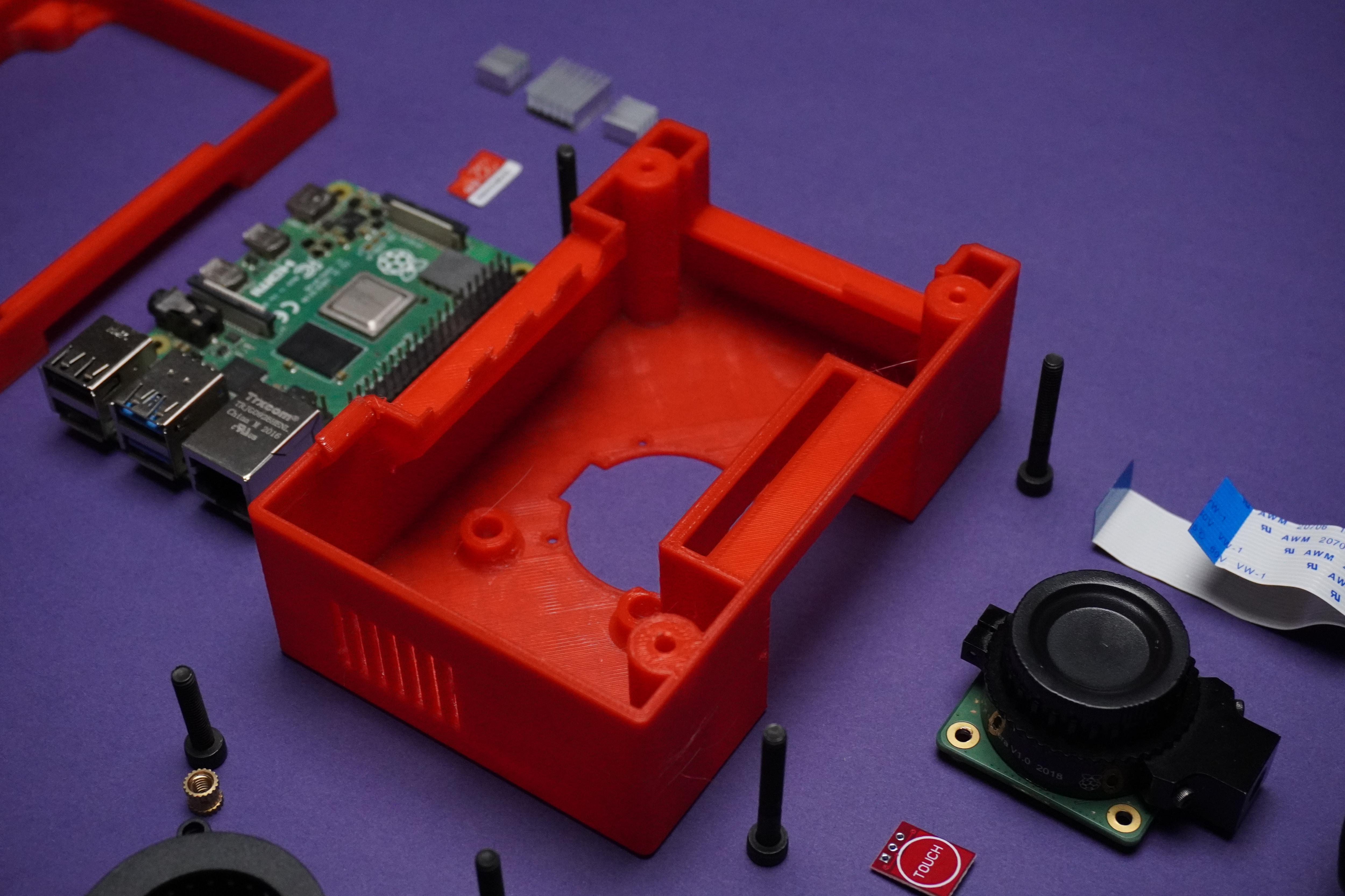
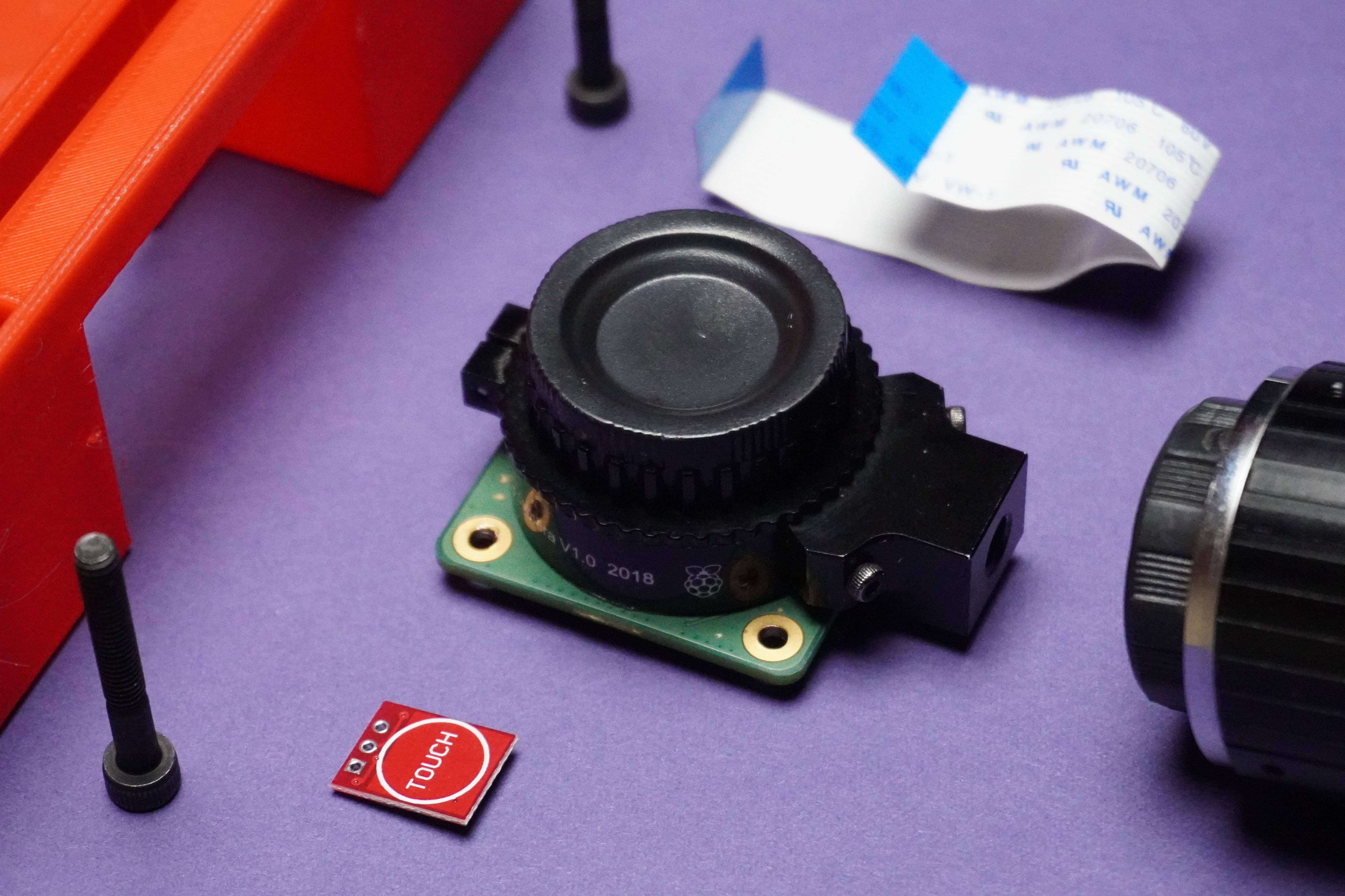
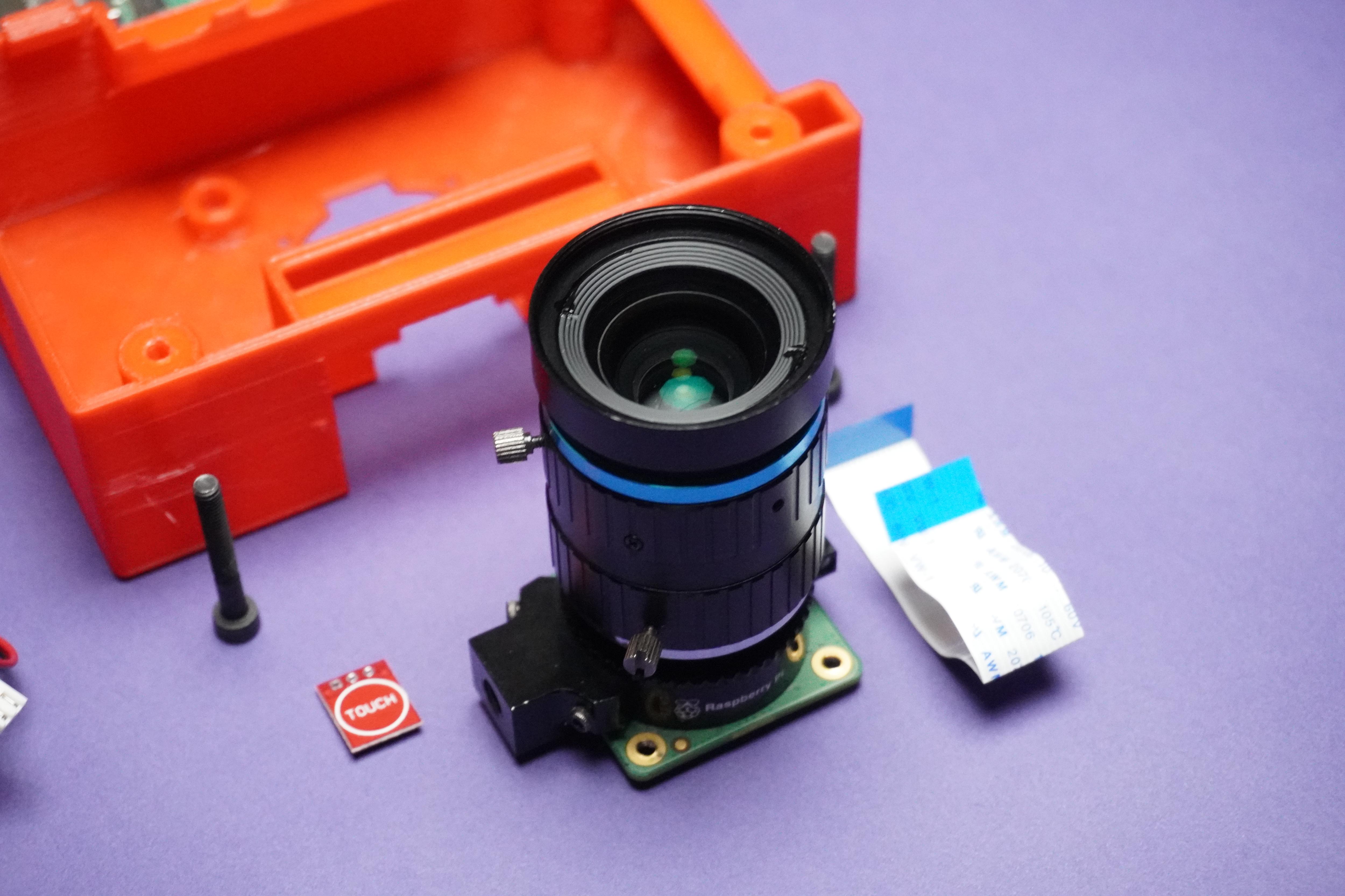
Components:
- 1x Raspberry Pi 4
- 1x DFRobot Raspberry Pi Touch Display
- 1x Raspberry Pi HQ Camera Module
- 1x 16mm Lens or 6mm Lens
- 1x Touch Sensor
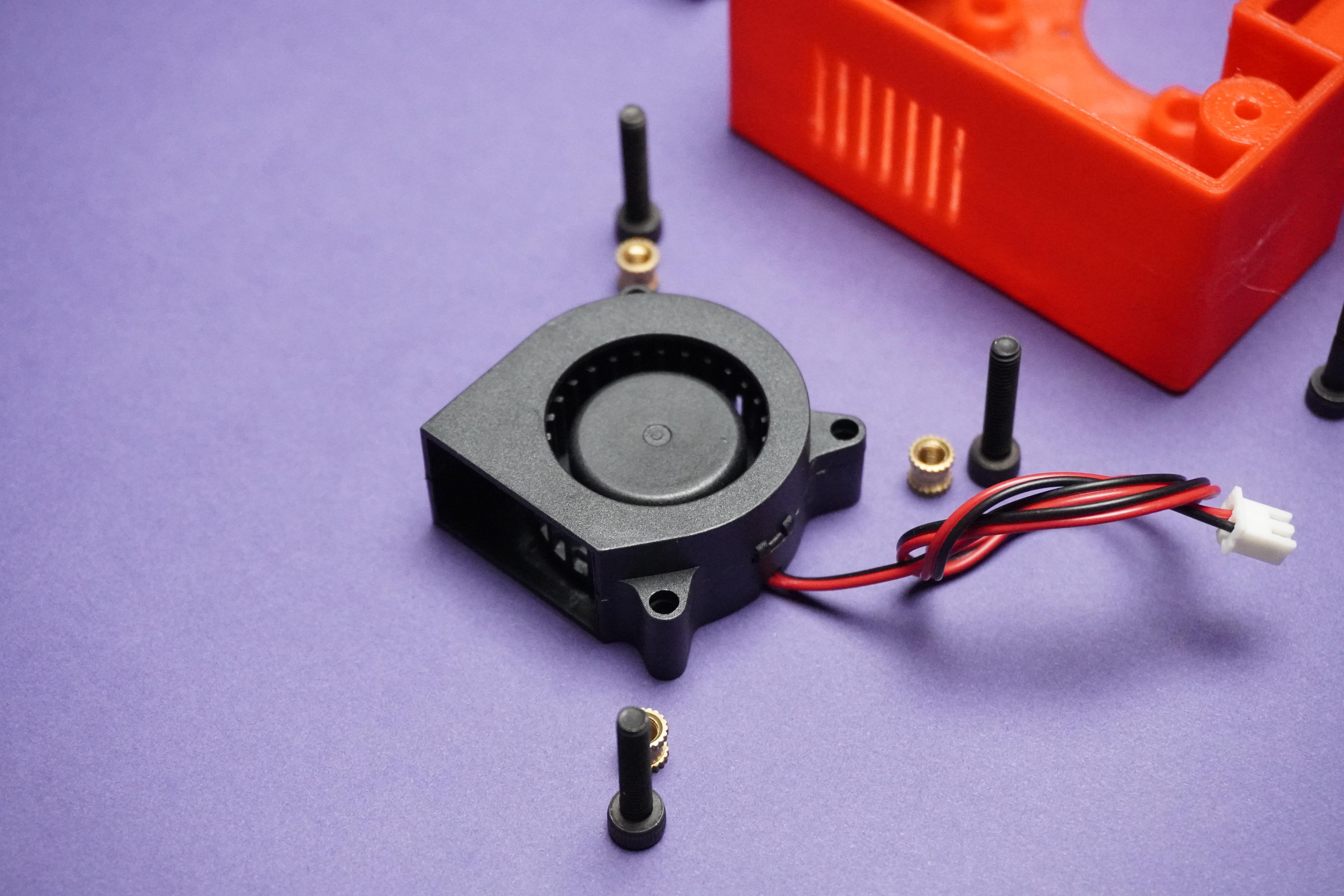
- 1x 5V 4020 Fan
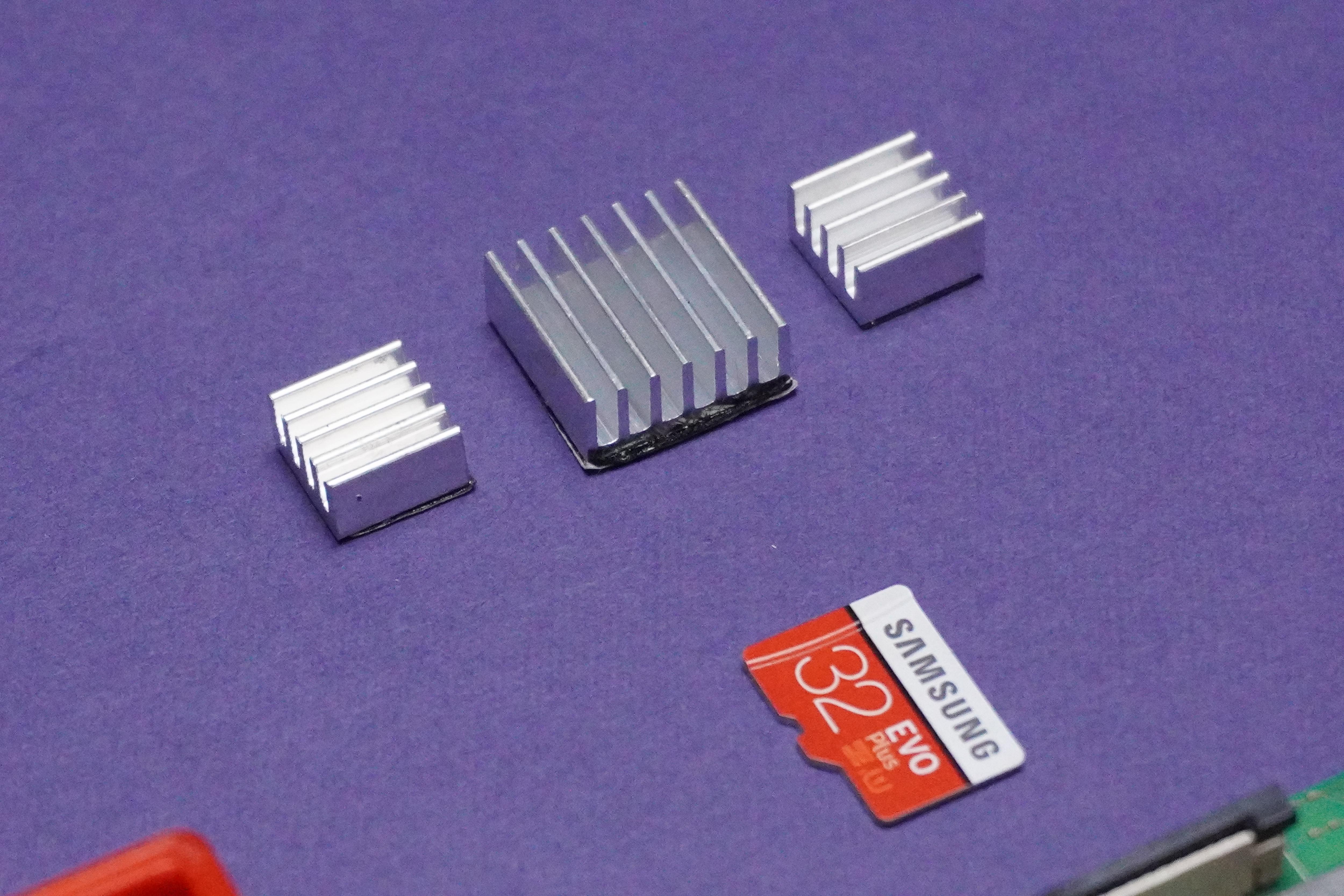
- 1x Raspberry Pi Heatsink Kit
- 1x SD Card
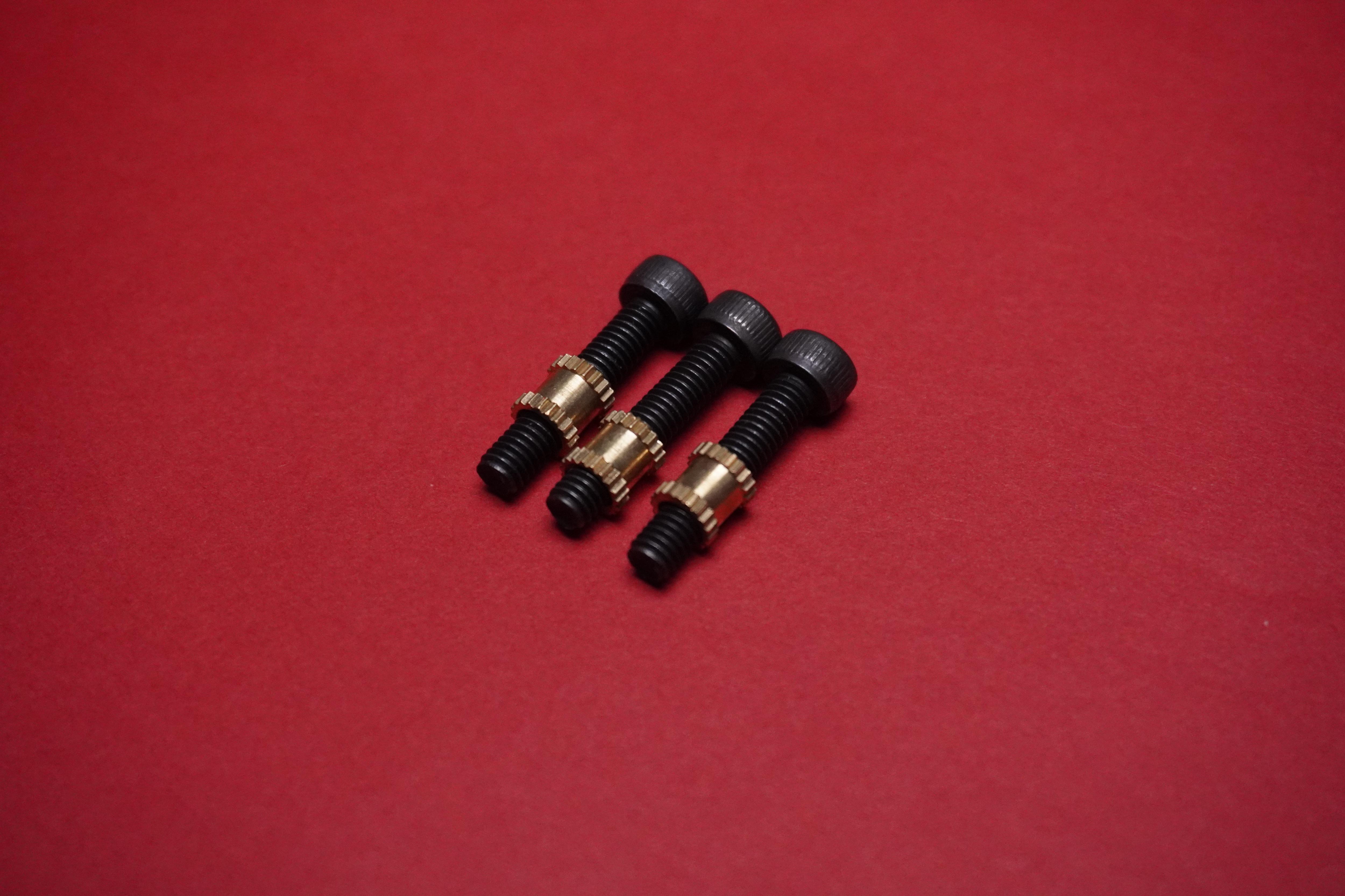
- 3x M3 30mm Screws
- 3x M3 20mm Screws
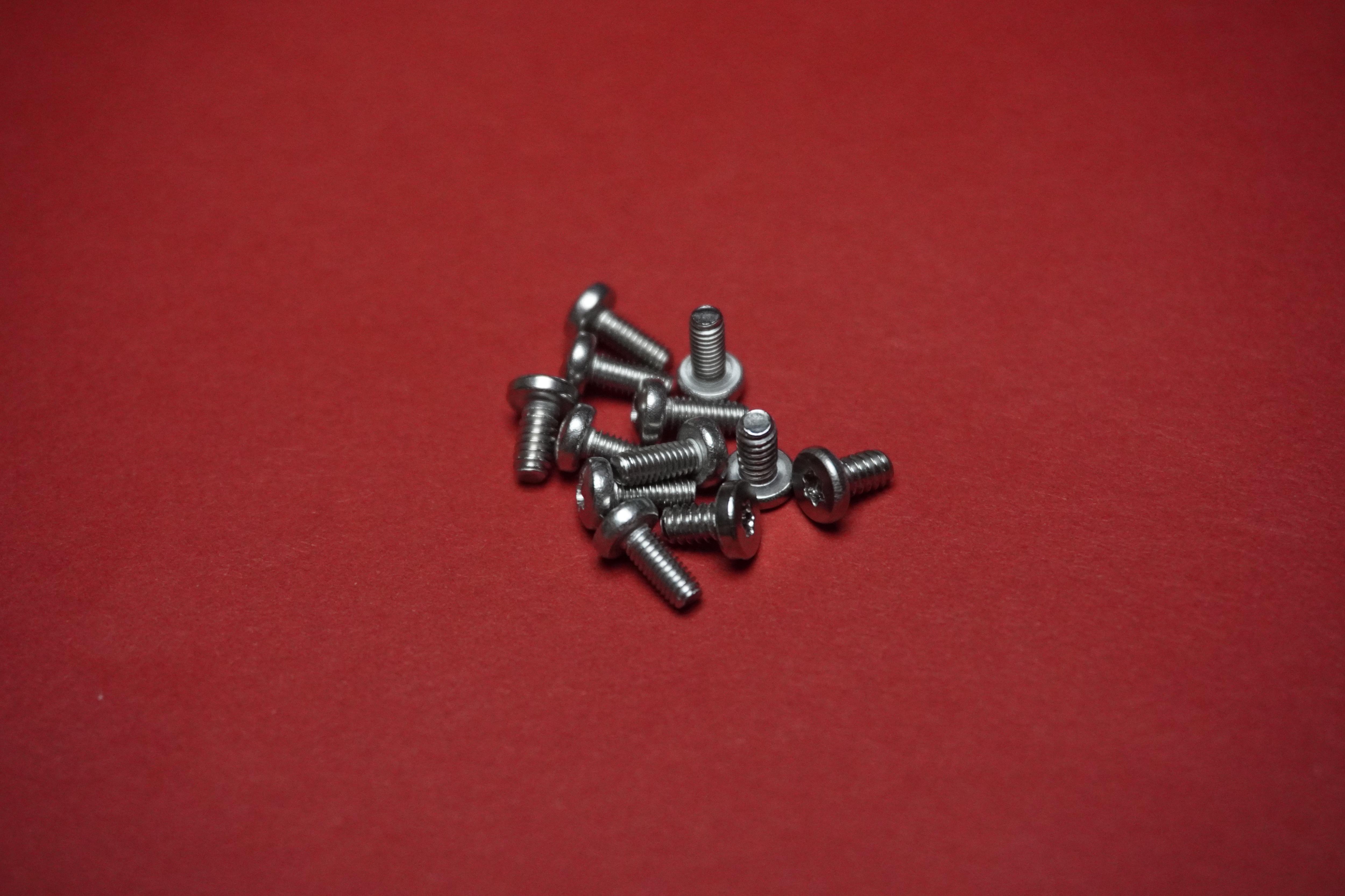
- 12x M2.5 8mm Screws
- 6x M3 Metal Inserts
Tools:
Software's:
About Fusion 360 Free Student and Educator License

Autodesk offers free licenses for students and educators, allowing them to access and use Autodesk products, including Fusion 360, for educational purposes. Here are some important details about the Fusion 360 Student and Educator license:
- Eligibility: The Fusion 360 Student and Educator license is available to students and educators who meet the eligibility criteria set by Autodesk. Students must be enrolled in a degree-granting educational institution, while educators must be employed by an accredited educational institution.
- Features: The license provides access to the full features and functionality of Fusion 360. This includes 3D modeling, simulation, rendering, CAM (computer-aided manufacturing), collaboration tools, and more. It allows students and educators to explore and learn various aspects of design and engineering.
- Duration: The Fusion 360 Student and Educator license is typically valid for one year. However, Autodesk periodically renews the license to ensure continued access for eligible students and educators.
- Educational Use: The license is specifically intended for educational use. Students can utilize Fusion 360 for classroom assignments, personal projects, research, and learning purposes. Educators can incorporate Fusion 360 into their curriculum, conduct workshops, and teach students using this software.
To access the Fusion 360 Student and Educator license, you can visit the Autodesk Education Community website and sign up for an account. Once your eligibility is verified, you will be granted access to download and install Fusion 360 using your educational license.
It's worth noting that while the Fusion 360 Student and Educator license is free, it is subject to certain terms and conditions outlined by Autodesk. These terms typically restrict the use of the software for commercial purposes. Therefore, if you intend to use Fusion 360 for commercial projects, you may need to consider purchasing a commercial license.
For the most accurate and up-to-date information on the Fusion 360 Student and Educator license, it is recommended to visit Autodesk's official website or contact their customer support.
Gathering Basic Components Information
I personally do the following steps before starting to design:
- Identify the electronic/other components I need for my project.
- Search online for CAD models: Look for websites or online libraries that provide CAD models for electronic components. I search on platforms like Autodesk Community Gallery, Tinkercad Gallery, Thingiverse or GrabCAD.
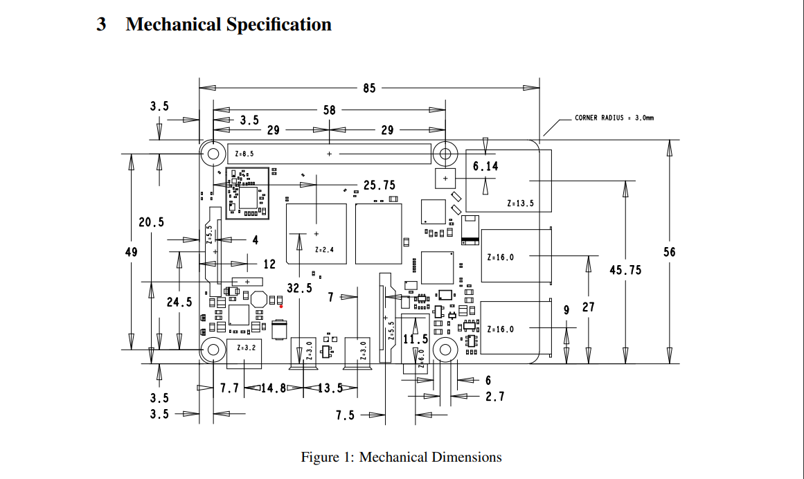
- Check datasheets: If I couldn't find a CAD model online, I search for the datasheet of the component. The datasheet typically contains important information, including mechanical dimensions, pin configurations, and other specifications that can help us to create the component in Fusion 360 accurately.
- Create custom components: If I couldn't find a CAD model or datasheet, I measure the dimensions of the physical component using measuring tools and create the components 3D model by myself. Fusion 360 provides tools for creating custom components using basic shapes, extrusions, and other modeling techniques. Use the dimensions and specifications from the datasheet to accurately model the component.
- I have found 3D model of Raspberry Pi on GrabCAD you can click here to view the Fusion 360 file Of Raspberry Pi 4 and use it in your design.
- I got Raspberry Pi HQ Camera module and lens model from Thingiverse.
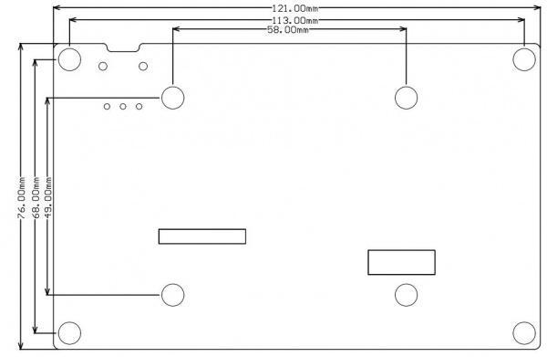
- I then collected the mechanical dimensions of the display from DFRobot's wiki page. Yes DFRobot has wiki page for each and every product that they have on their website, its amazing right?
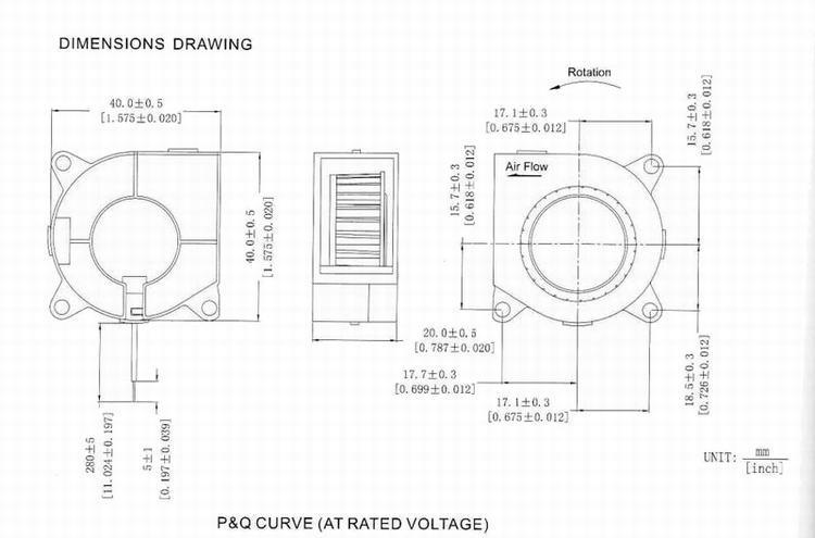
- Then I got few dimensions of the 5V 4020 fan from the internet and I used scale for measuring the dimension of opening mouth of the fan.
Follow the below steps to use this info in the design.
Designing the Touch Display
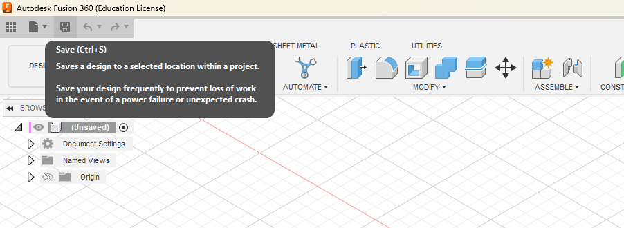
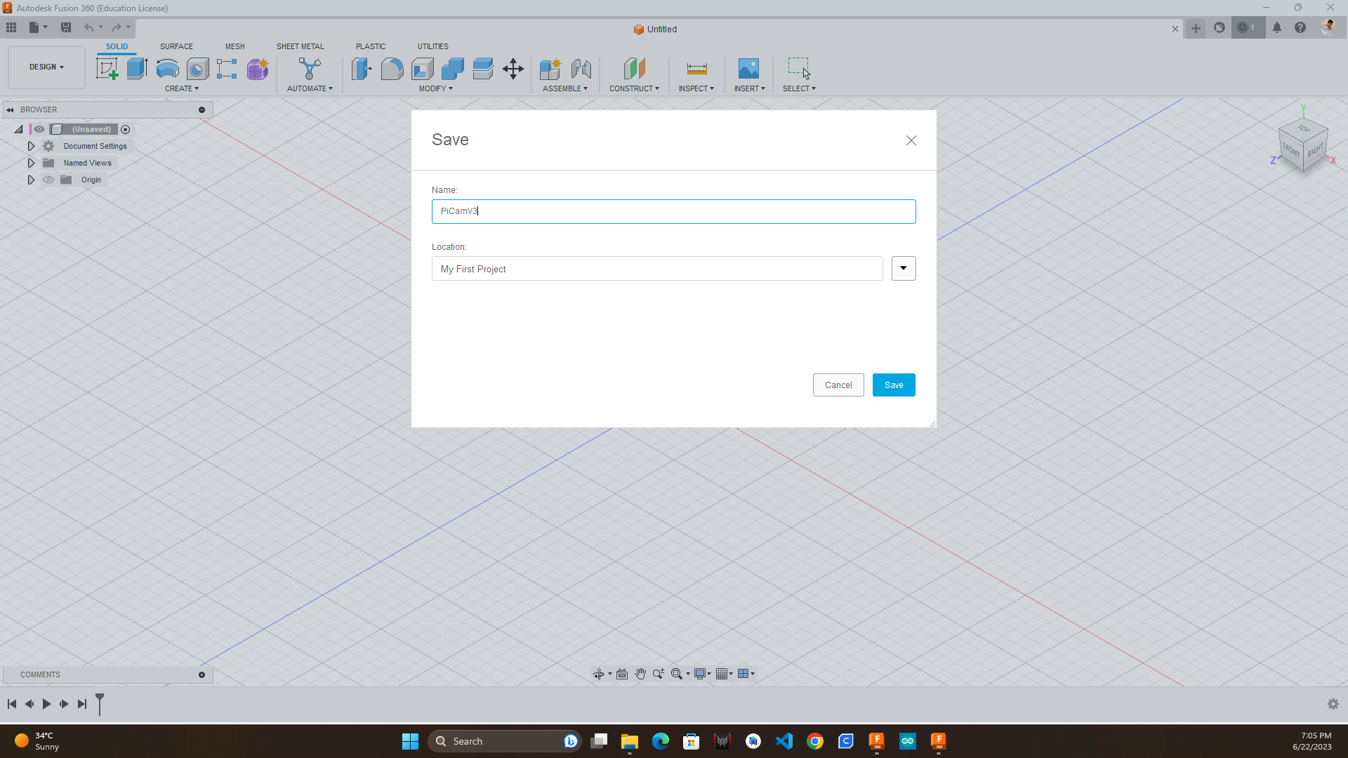
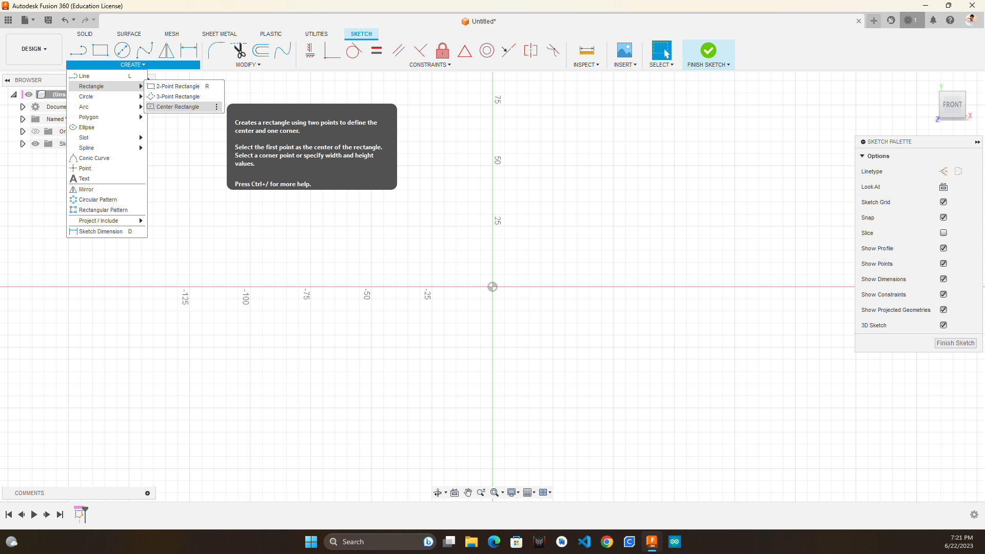
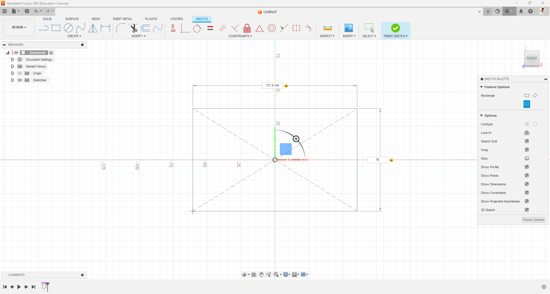
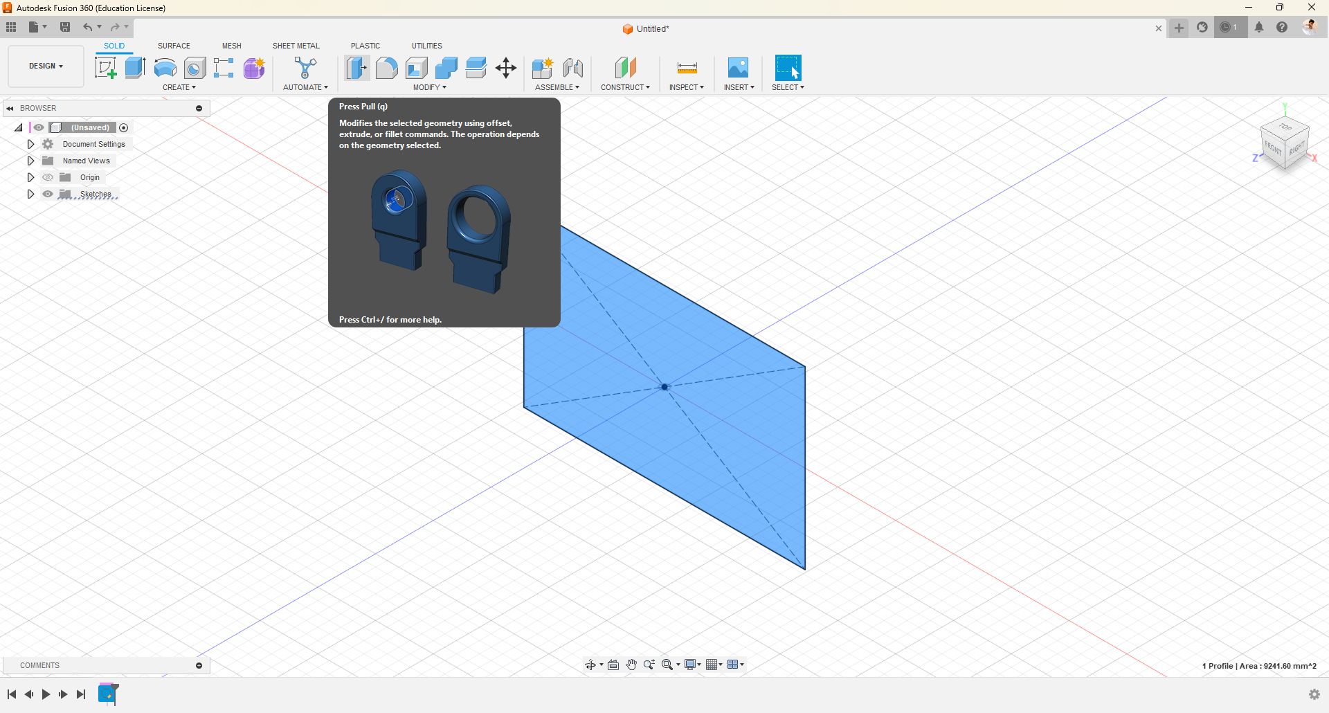
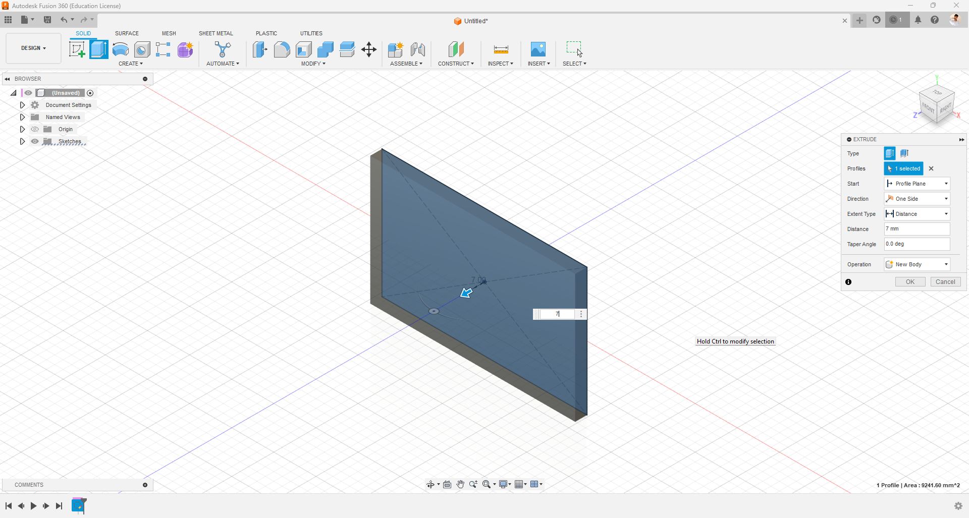
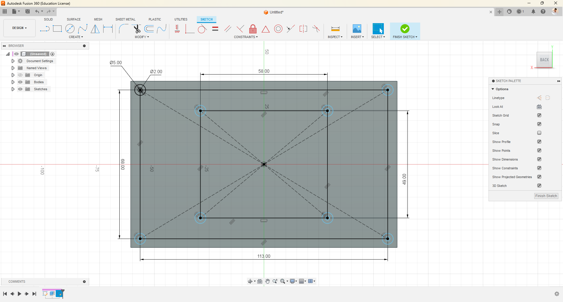
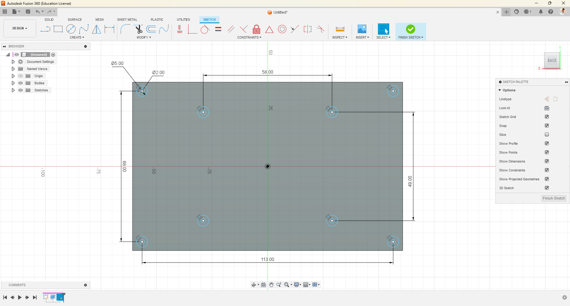
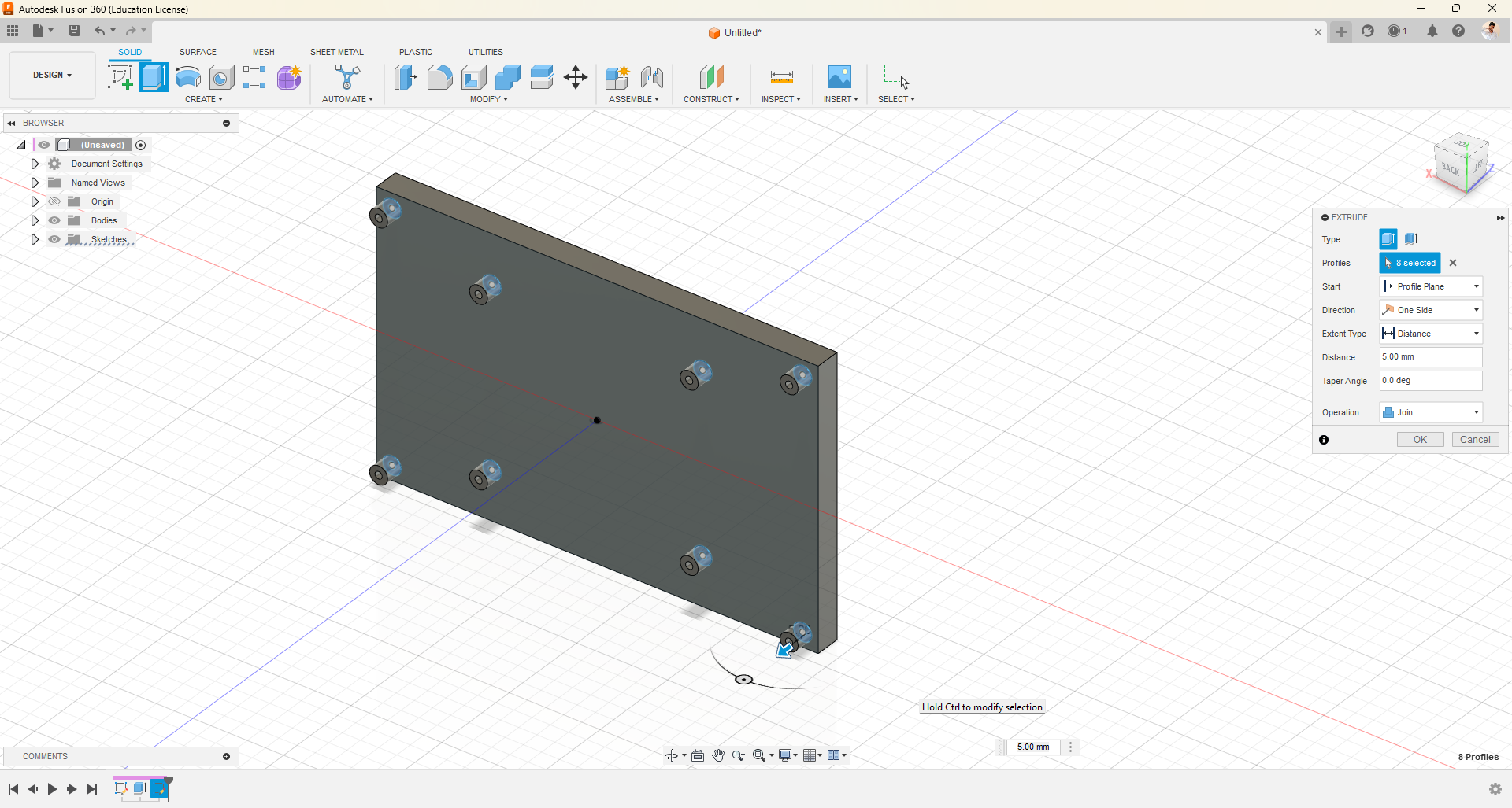
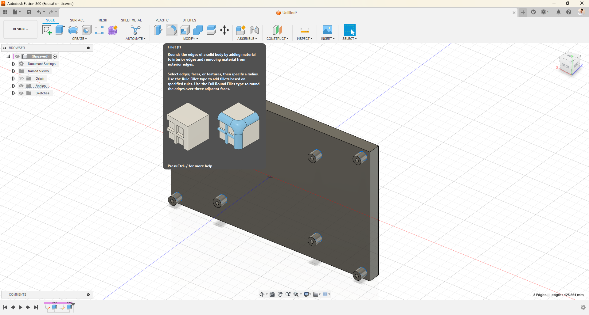
- First, launch the Fusion 360 software and save the project.
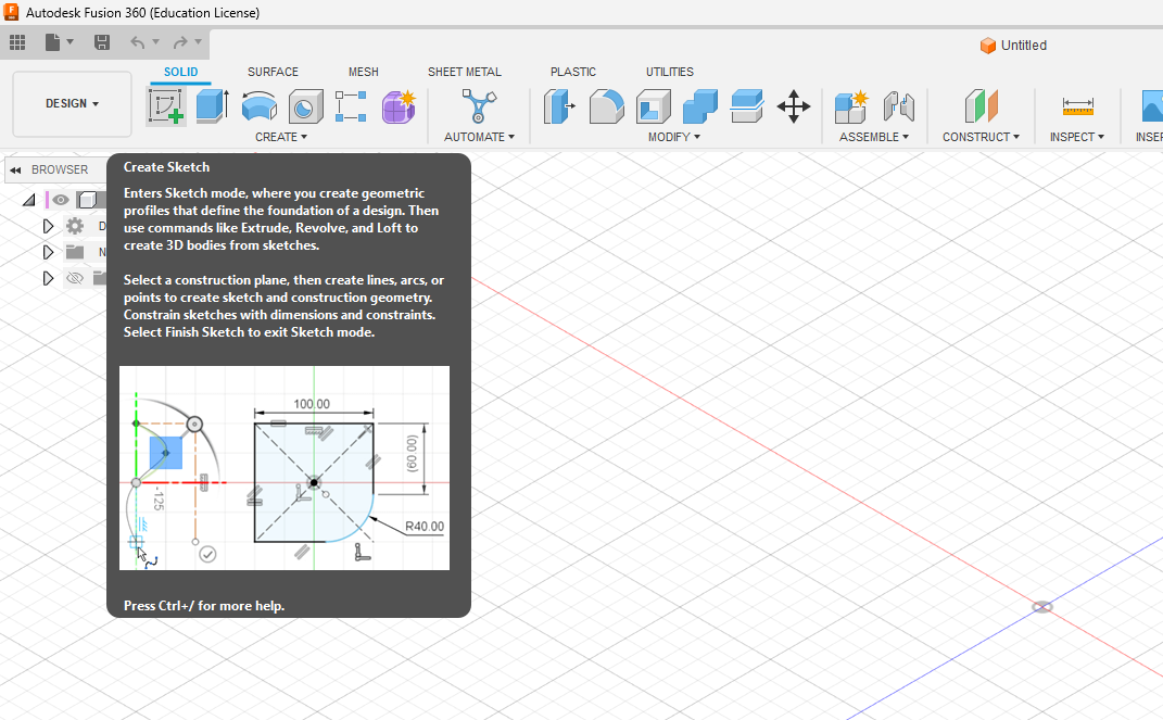
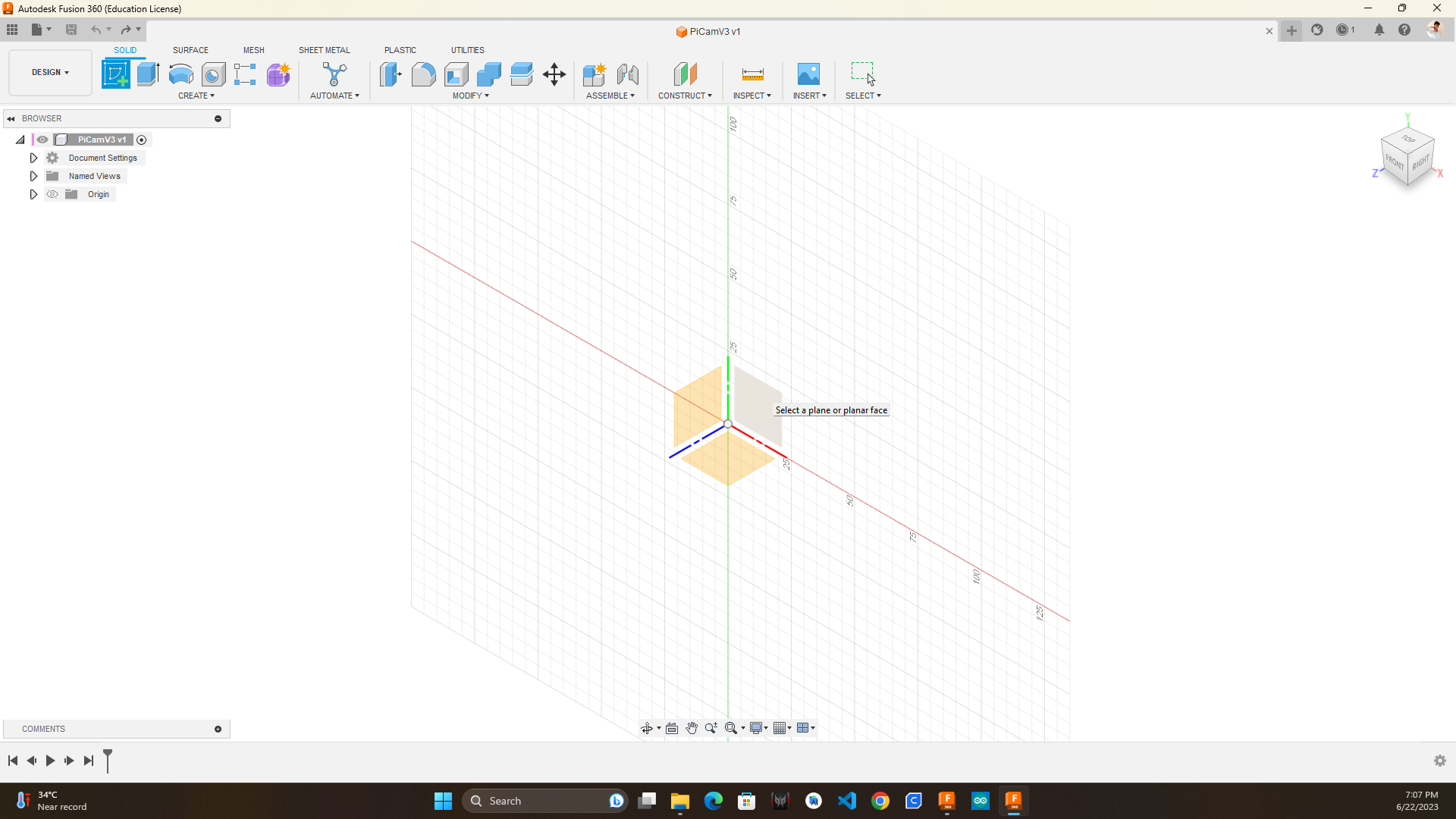
- Next, click on "Create Sketch" to draw 2D shapes. Choose the desired plane on which you want to draw.
- I have drawn the dimensions of the display (121x76mm) with a 0.6mm offset. When I measured the display, I noticed that it was slightly larger in one direction. To ensure that the display fits properly in the case when 3D printed, I added the offset.
- Then, use the "Press Pull" option. Click on the 2D rectangular surface and enter the thickness of the display (7mm) to convert the 2D diagram into a 3D object.
- Select the back surface of the display object and create a sketch on top of it for the other features of the display.
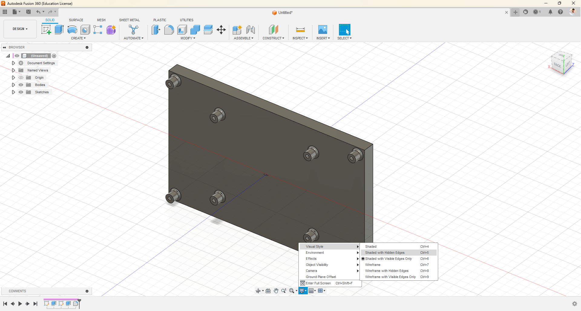
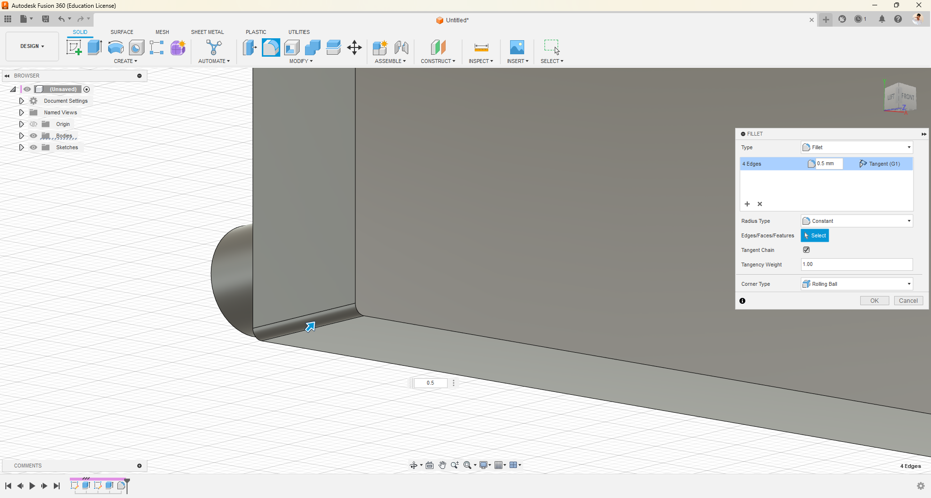
- Once again, use the "Press Pull" option and then apply the "Fillet" feature to round the edges of the display.
Designing Fan Case
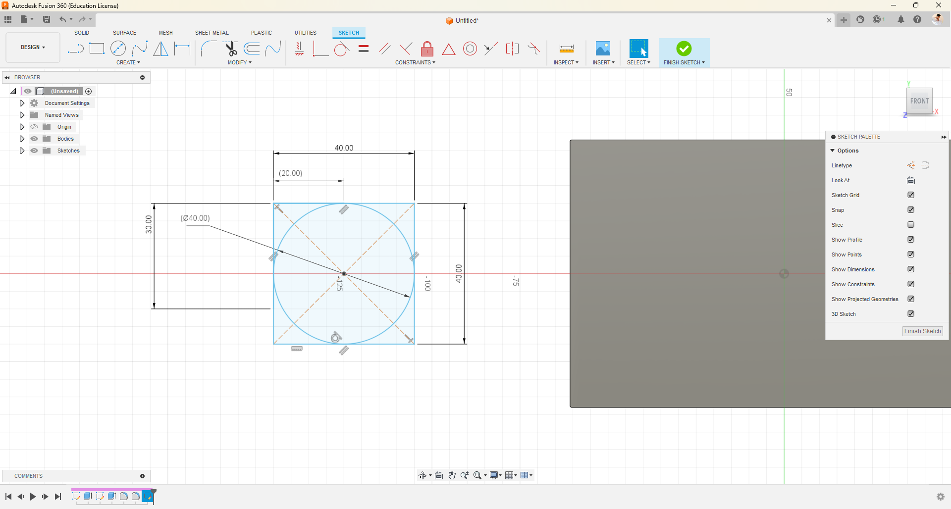
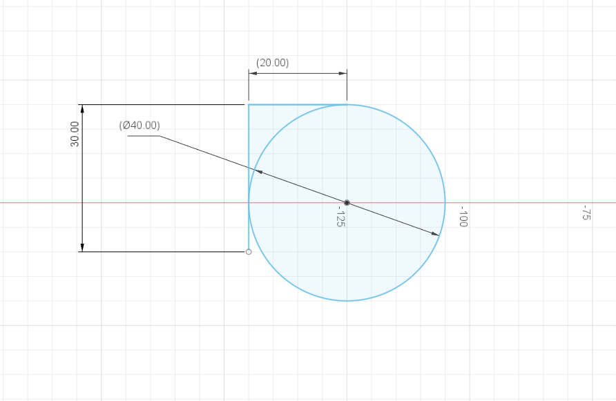
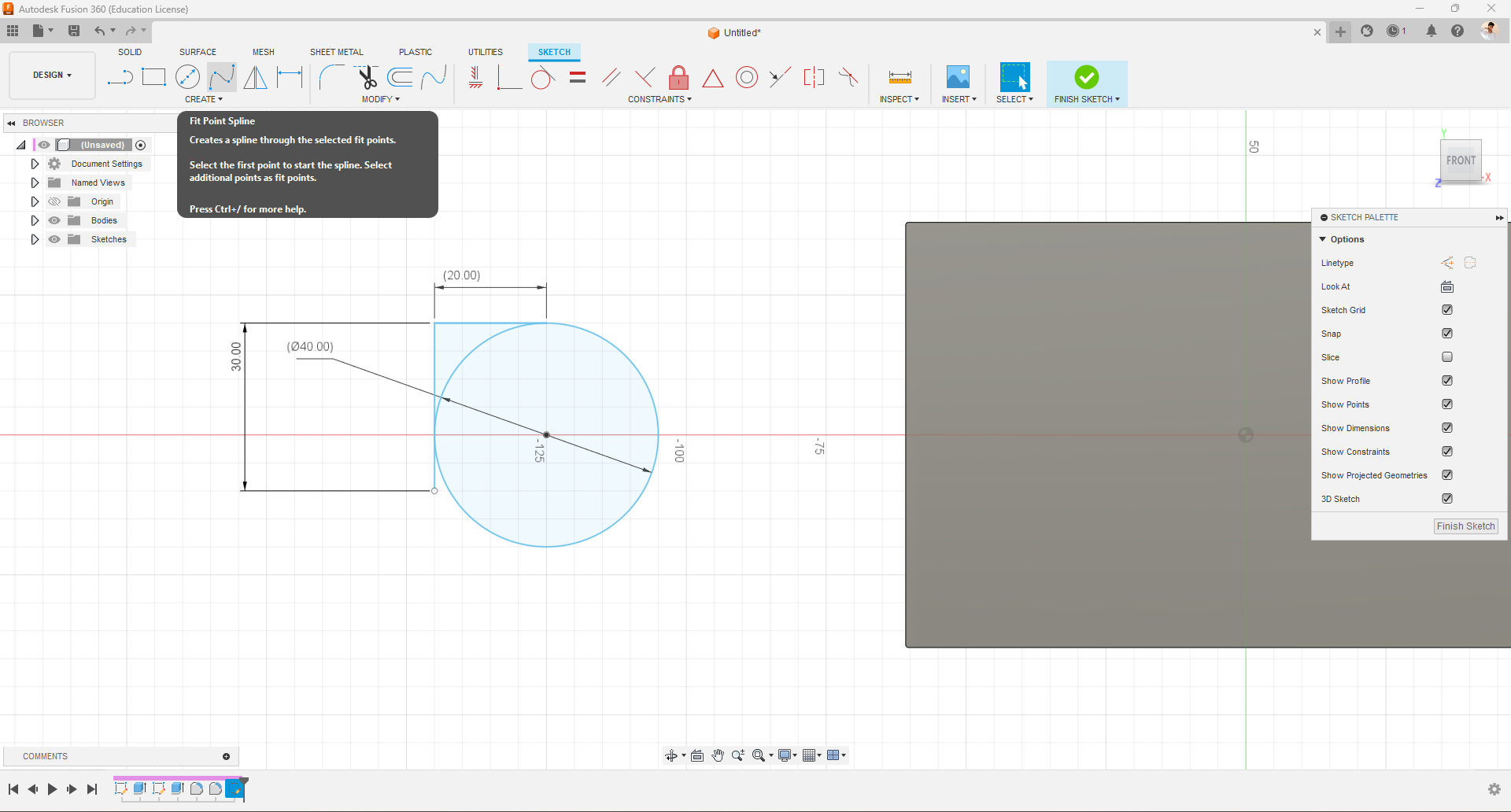
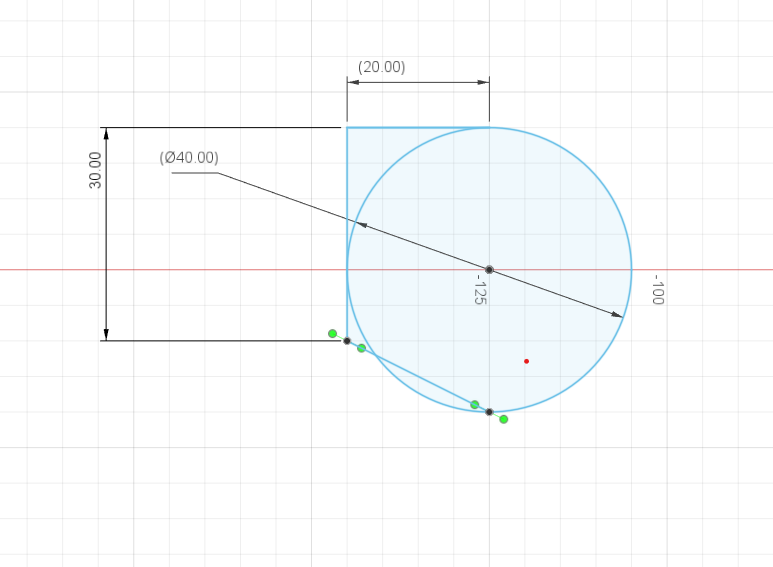
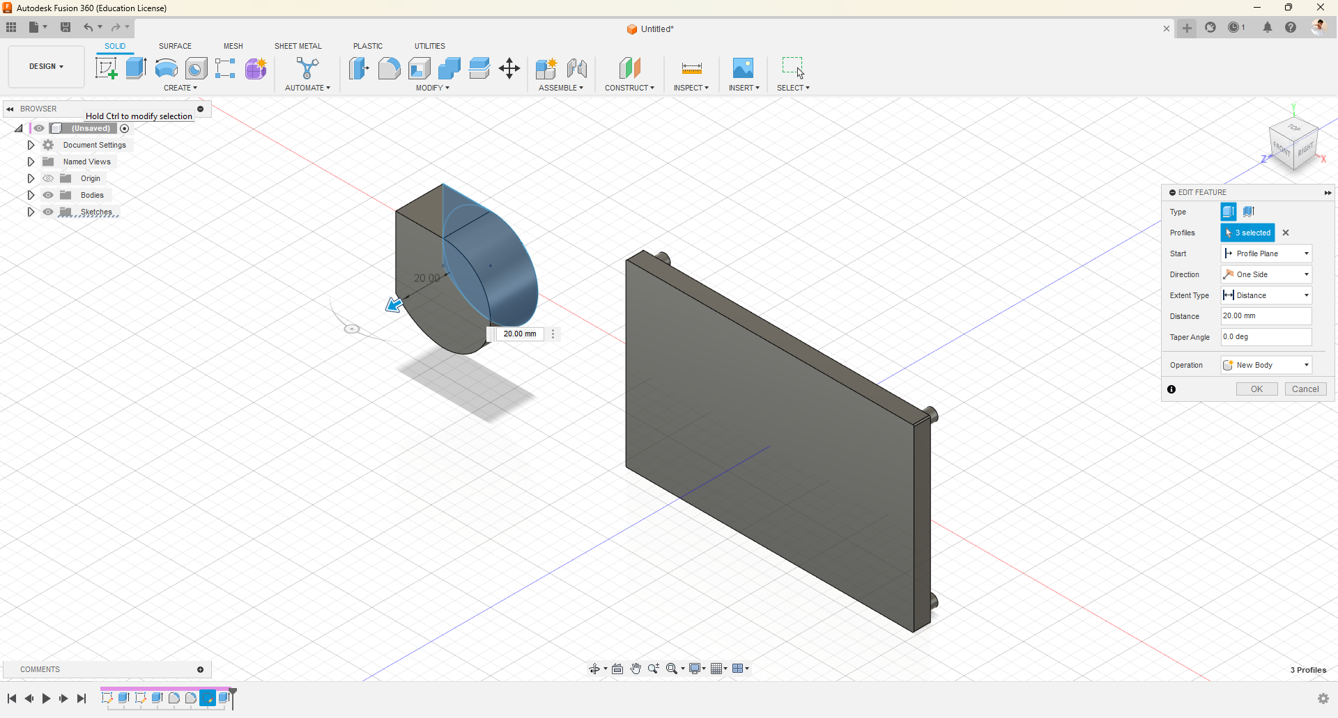
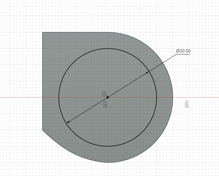
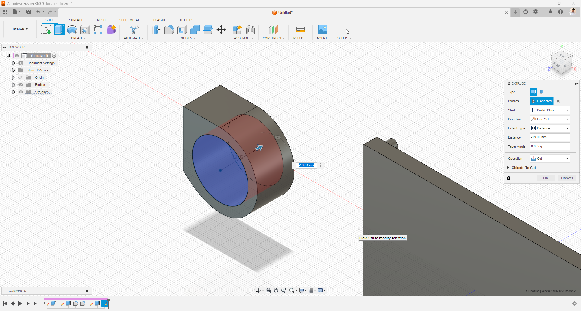
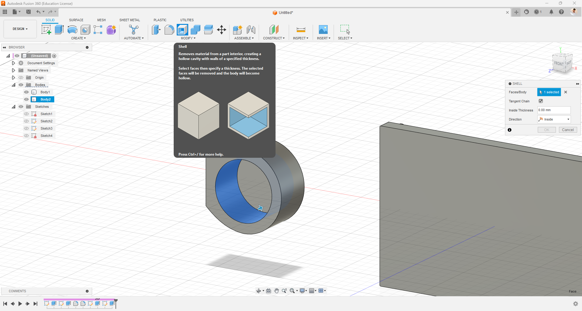
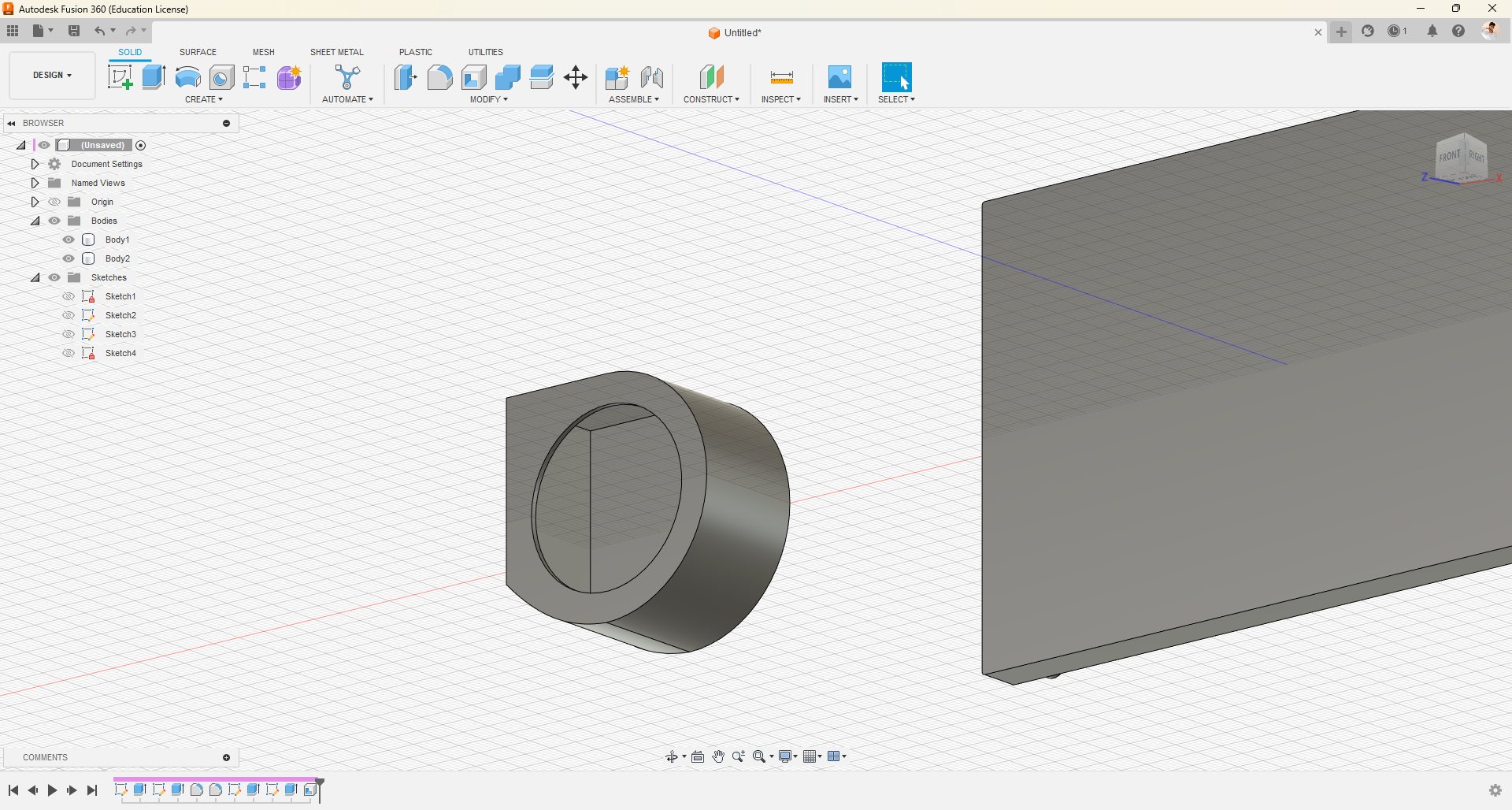
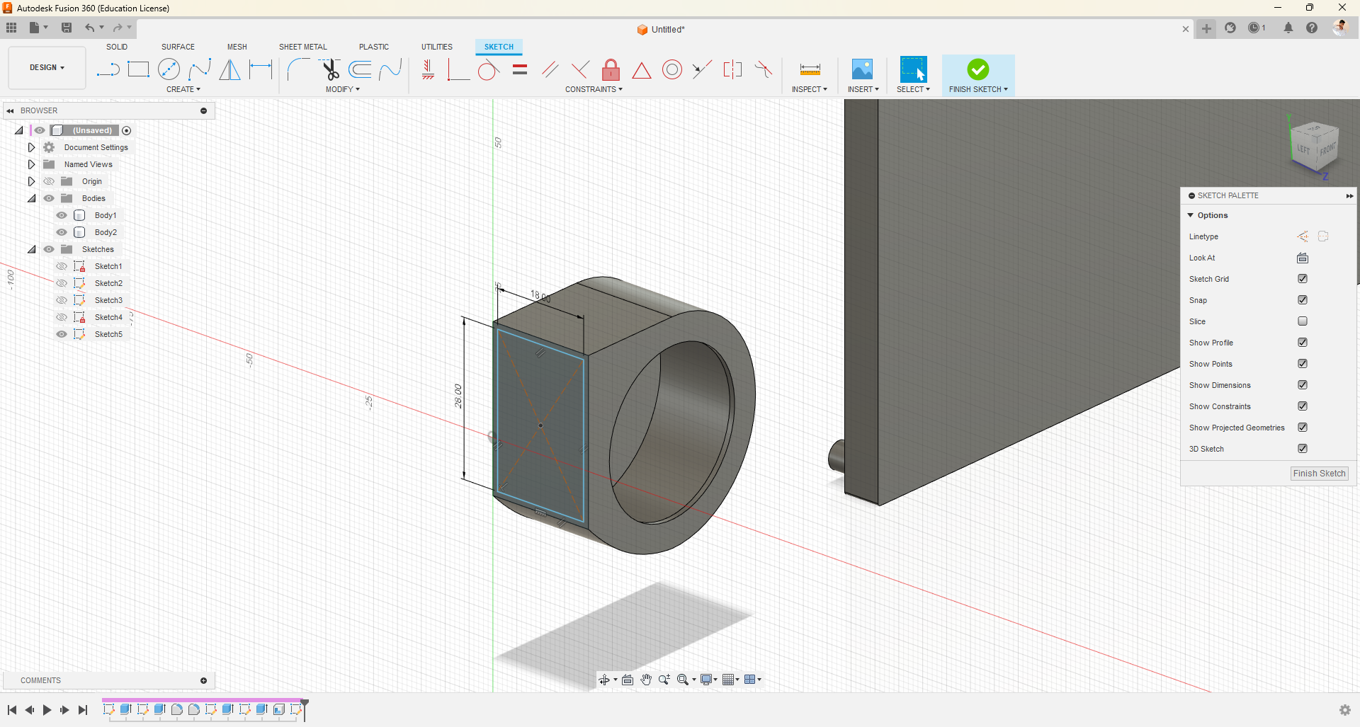
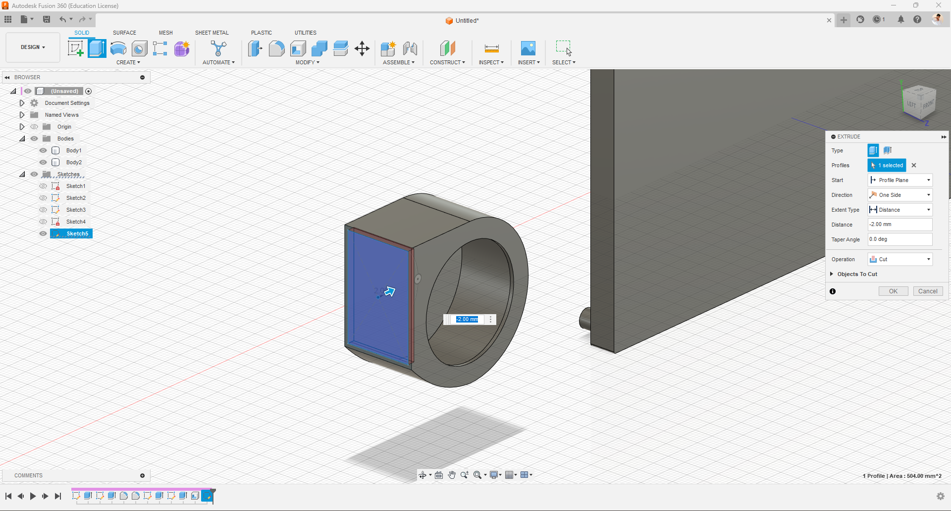
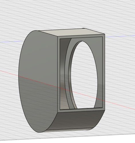
- To design the fan, first, I drew the outer dimensions of the fan as a 40x40mm rectangle and a 40mm diameter circle. I also drew two lines from one corner, measuring 30mm and 20mm respectively, and then deleted the rectangle as it was only for reference.
- To determine the length of the fan's opening, I measured it using a scale, and it was found to be 30mm.
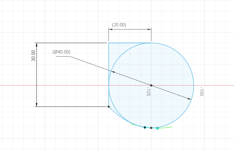
- Next, I used the Fit Point Spline option to draw a curved line. I utilized the green dots to create the curved shape, although it may not be entirely accurate, I attempted to match the desired shape as closely as possible.
- Subsequently, by selecting the surfaces using the Ctrl key and mouse, I used the "press pull" function to extrude the shape to a height of 20mm.
- Following that, I drew a 30mm circle on top of the object and pressed it to a height of 19mm.
- To make the object hollow with a 1mm wall thickness, I selected the inner surface and used the Shell option.
- Lastly, I drew a center rectangle with dimensions of 28x18mm and pressed it to create the opening of the fan.
Designing Fan Propeller
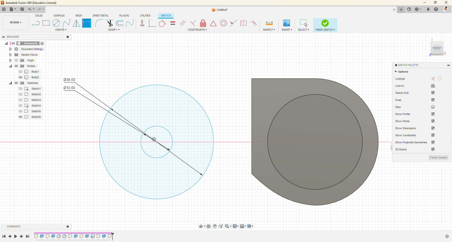
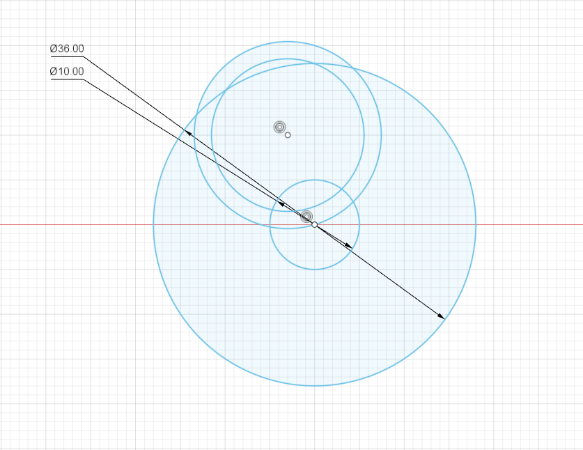
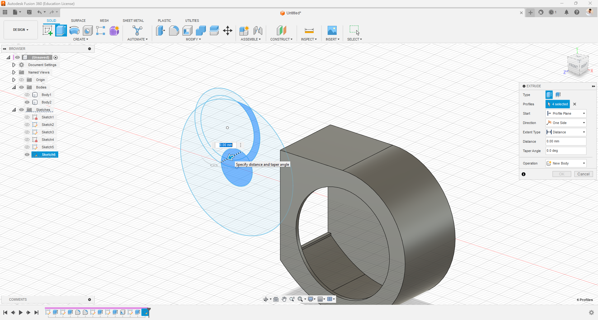
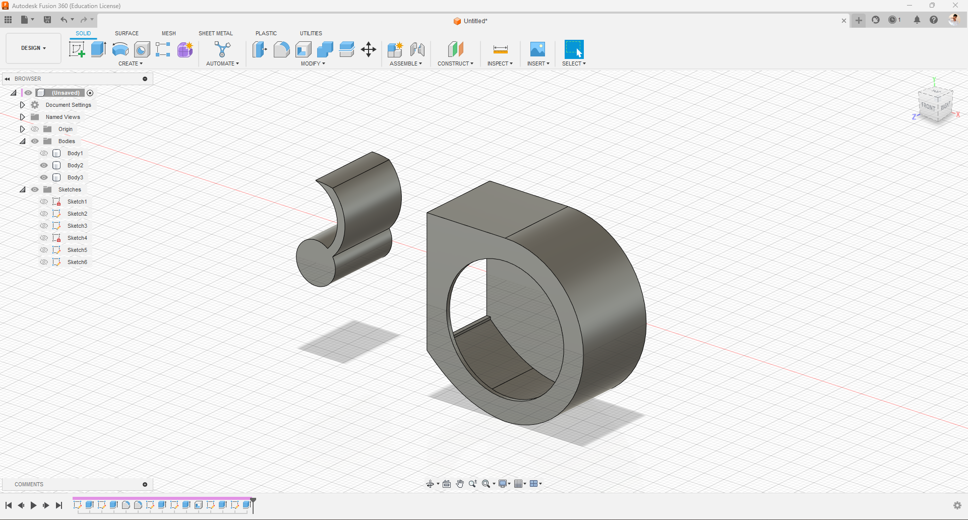
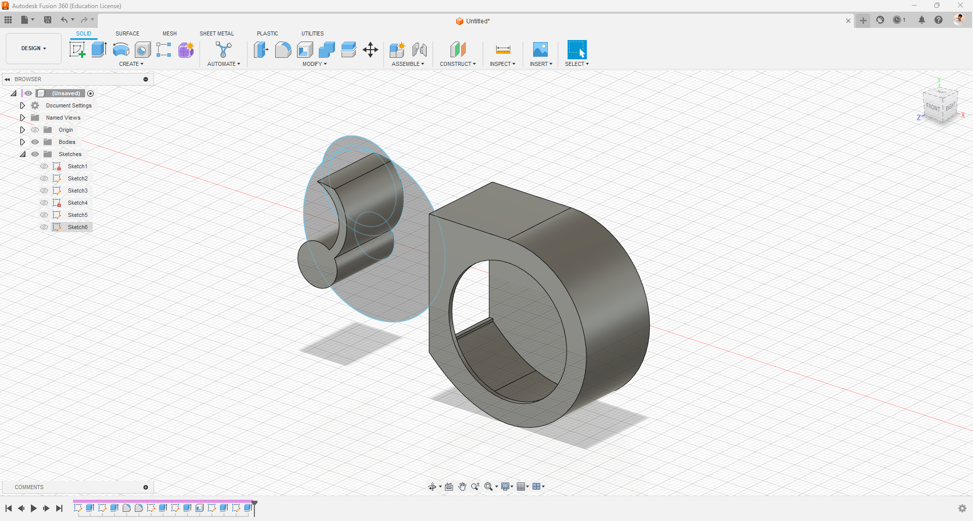
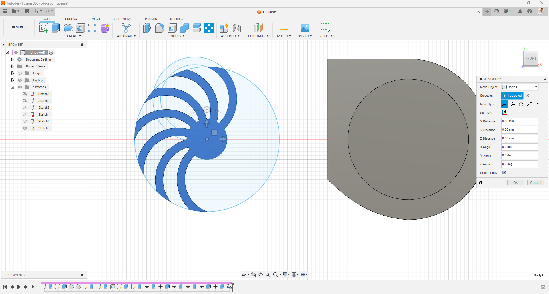
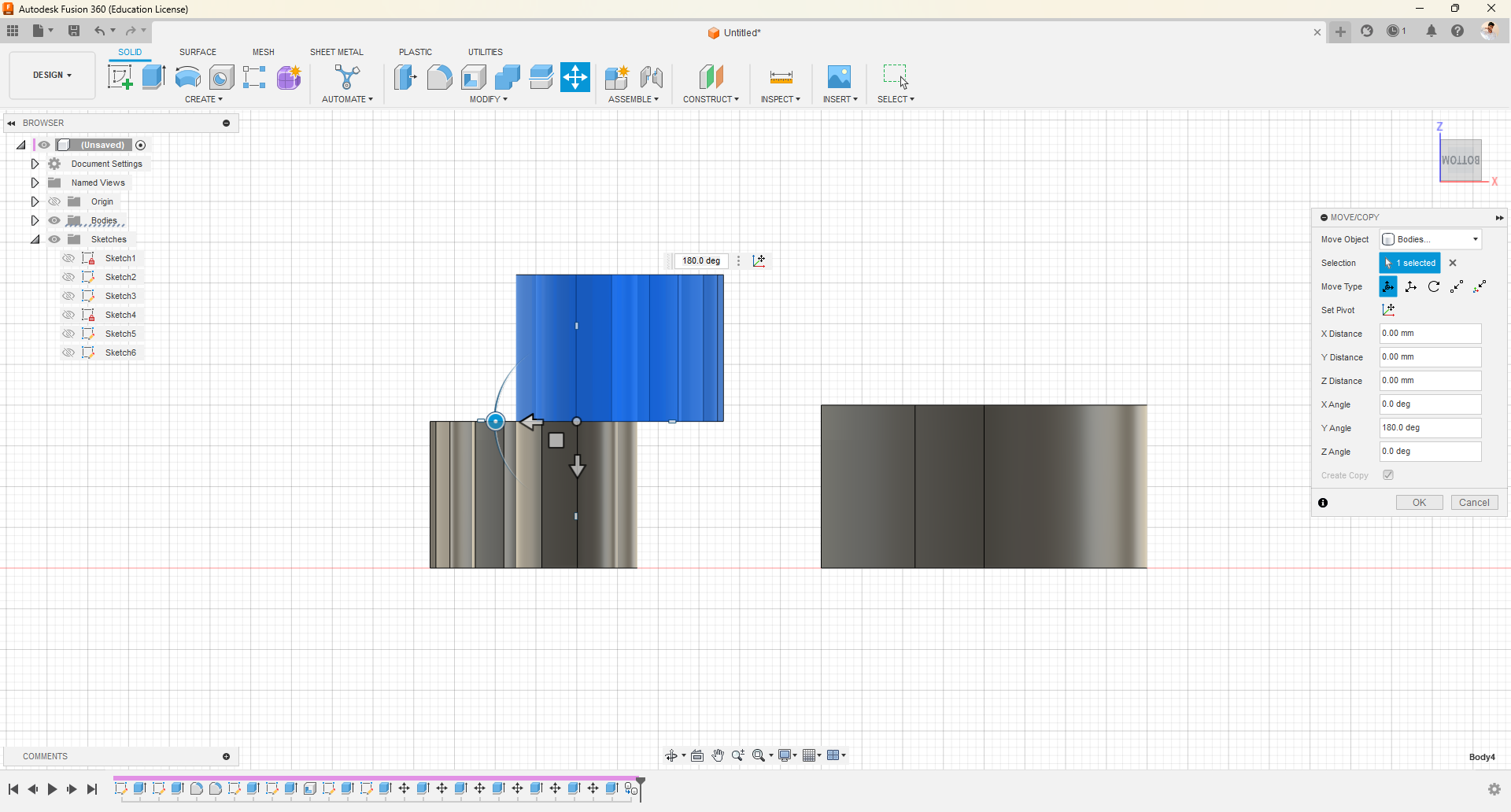
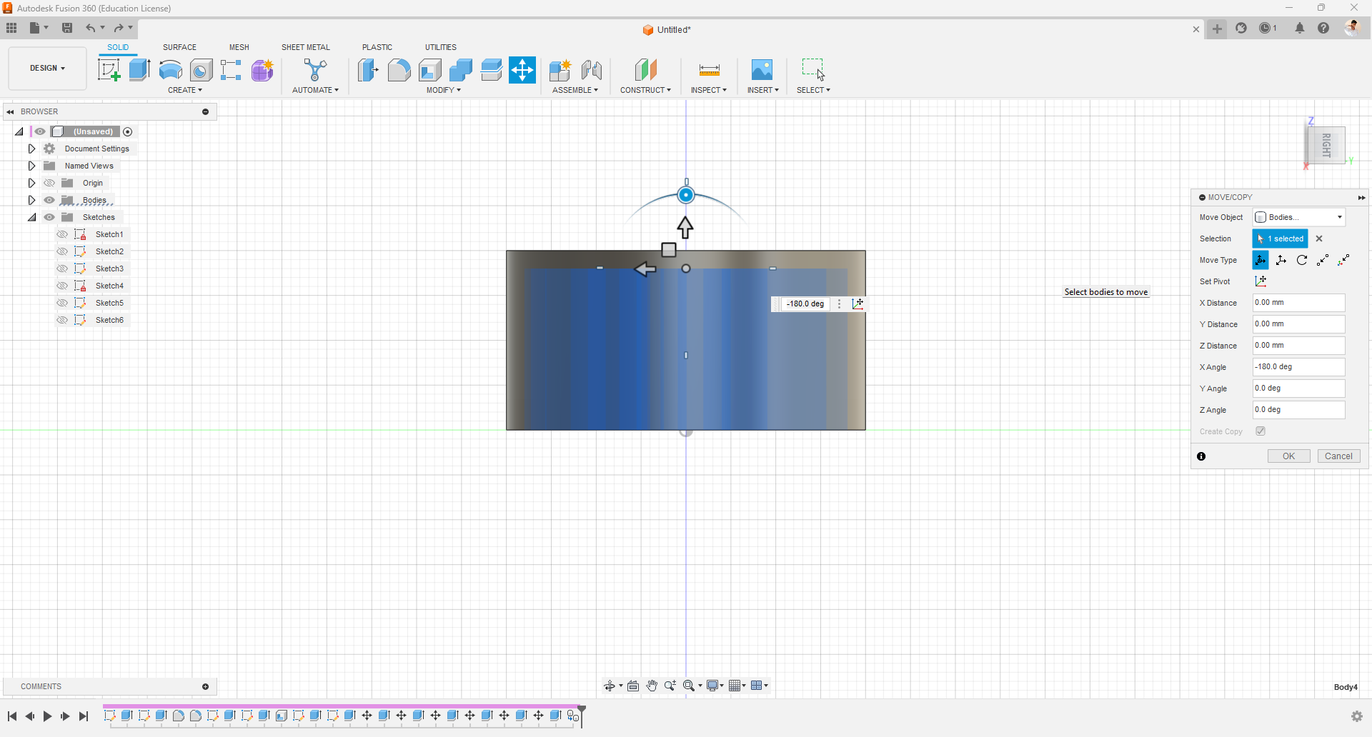
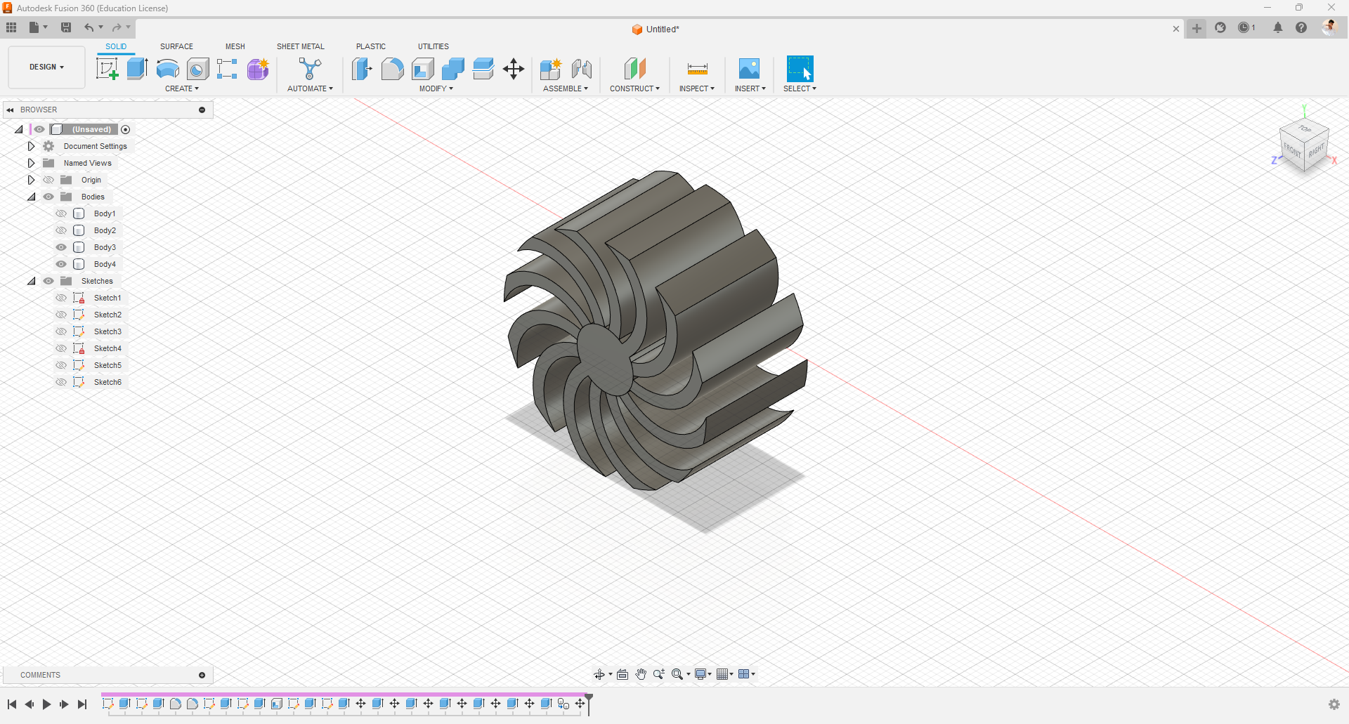
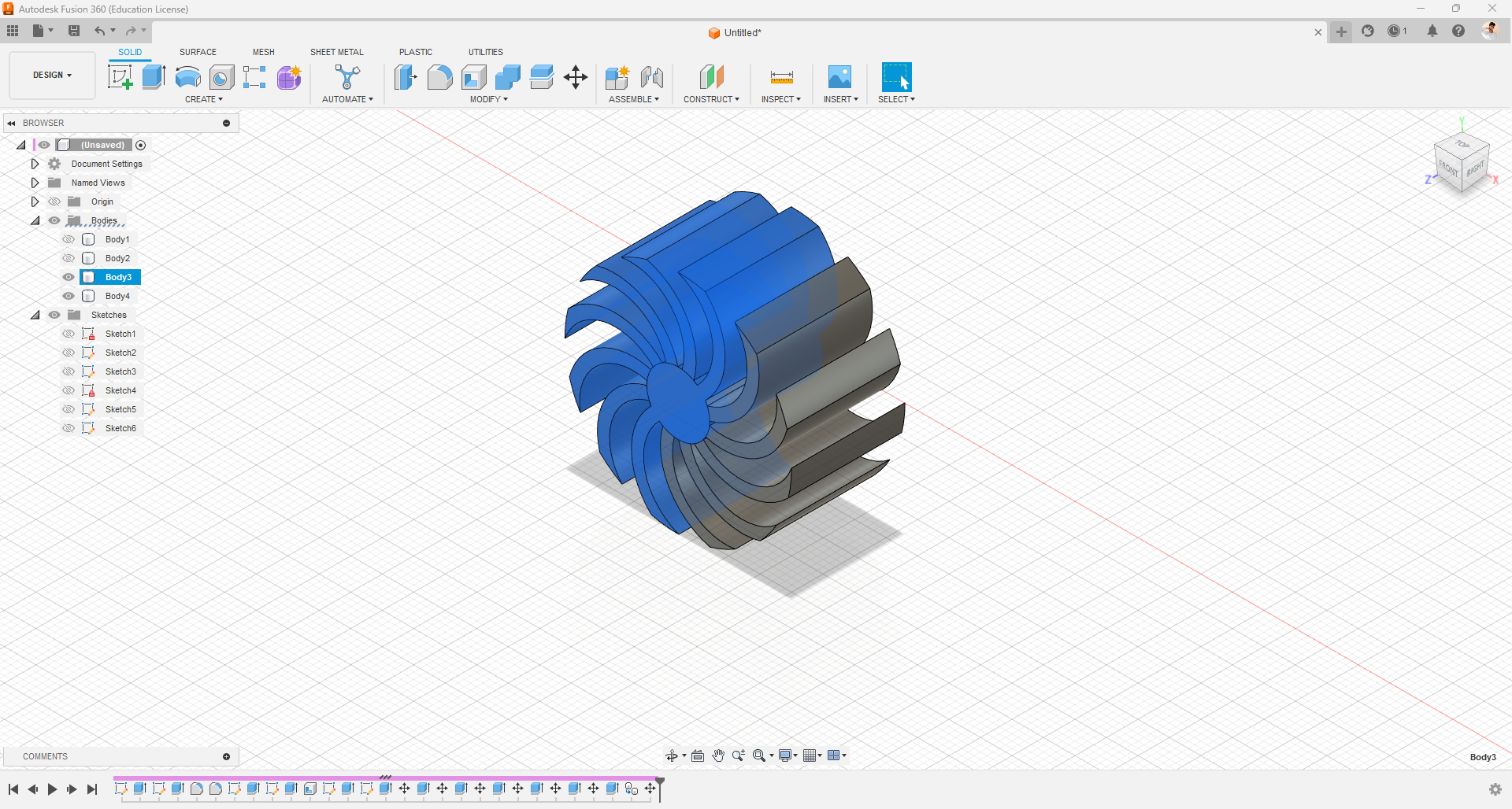
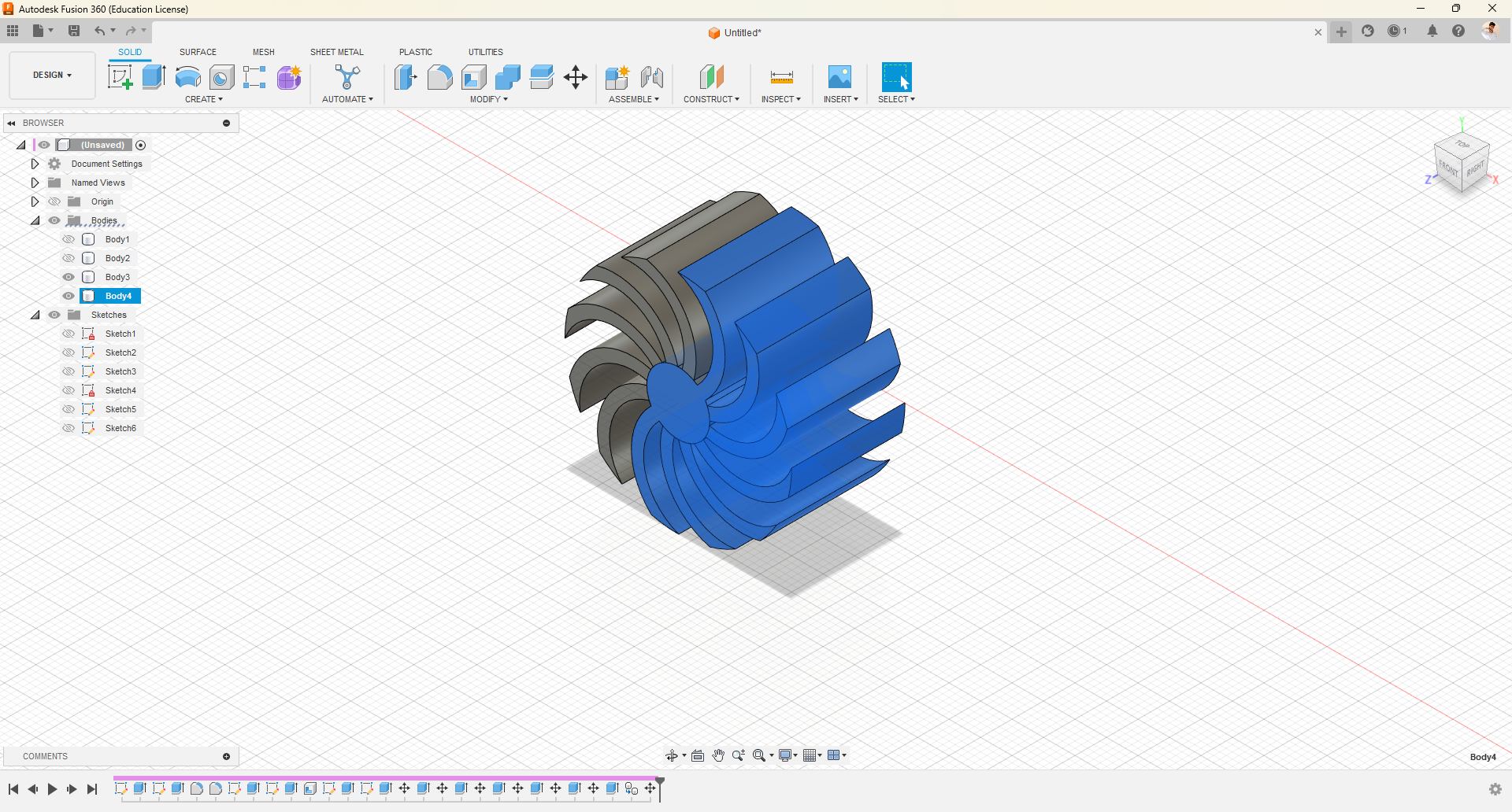
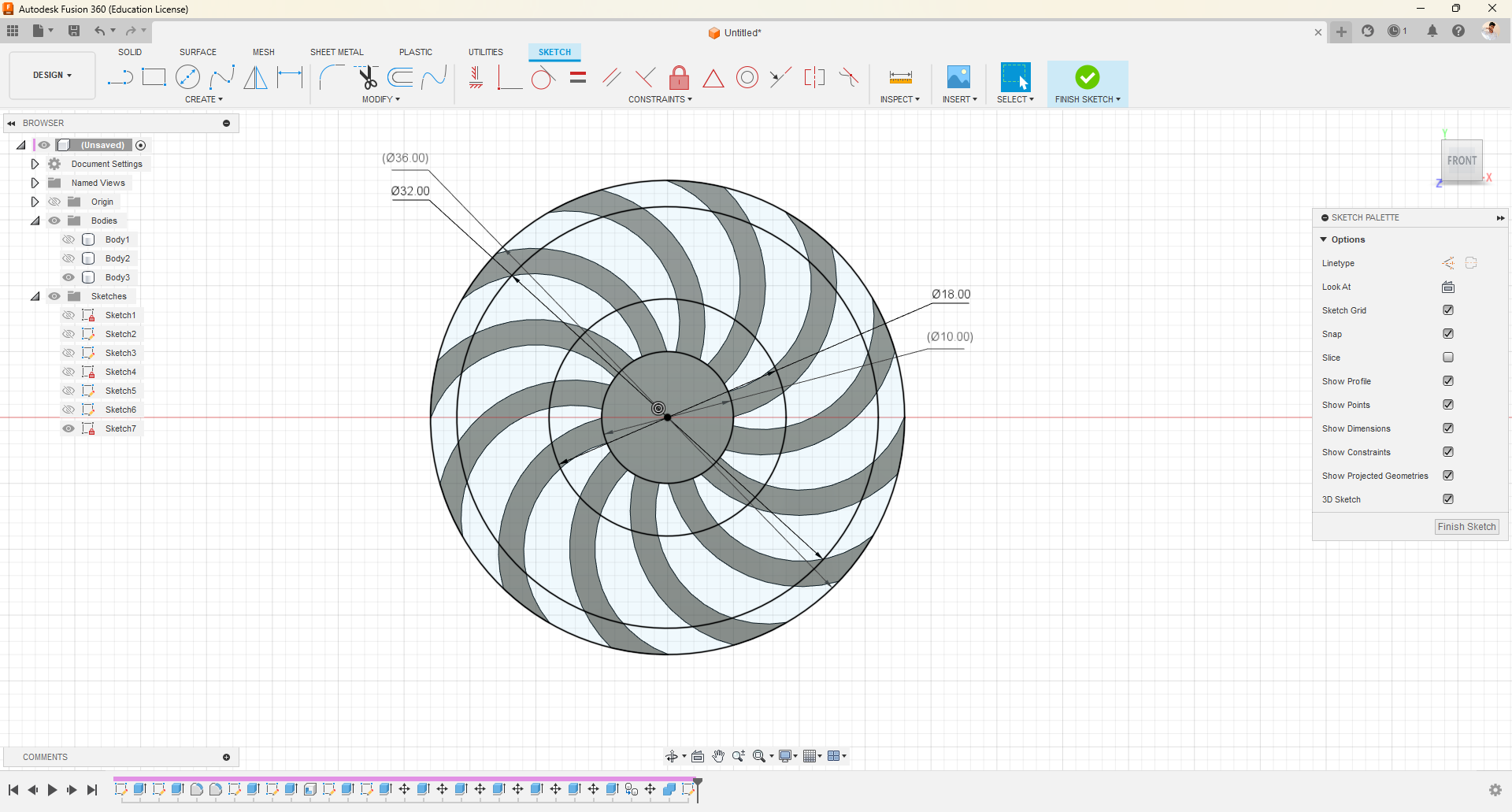
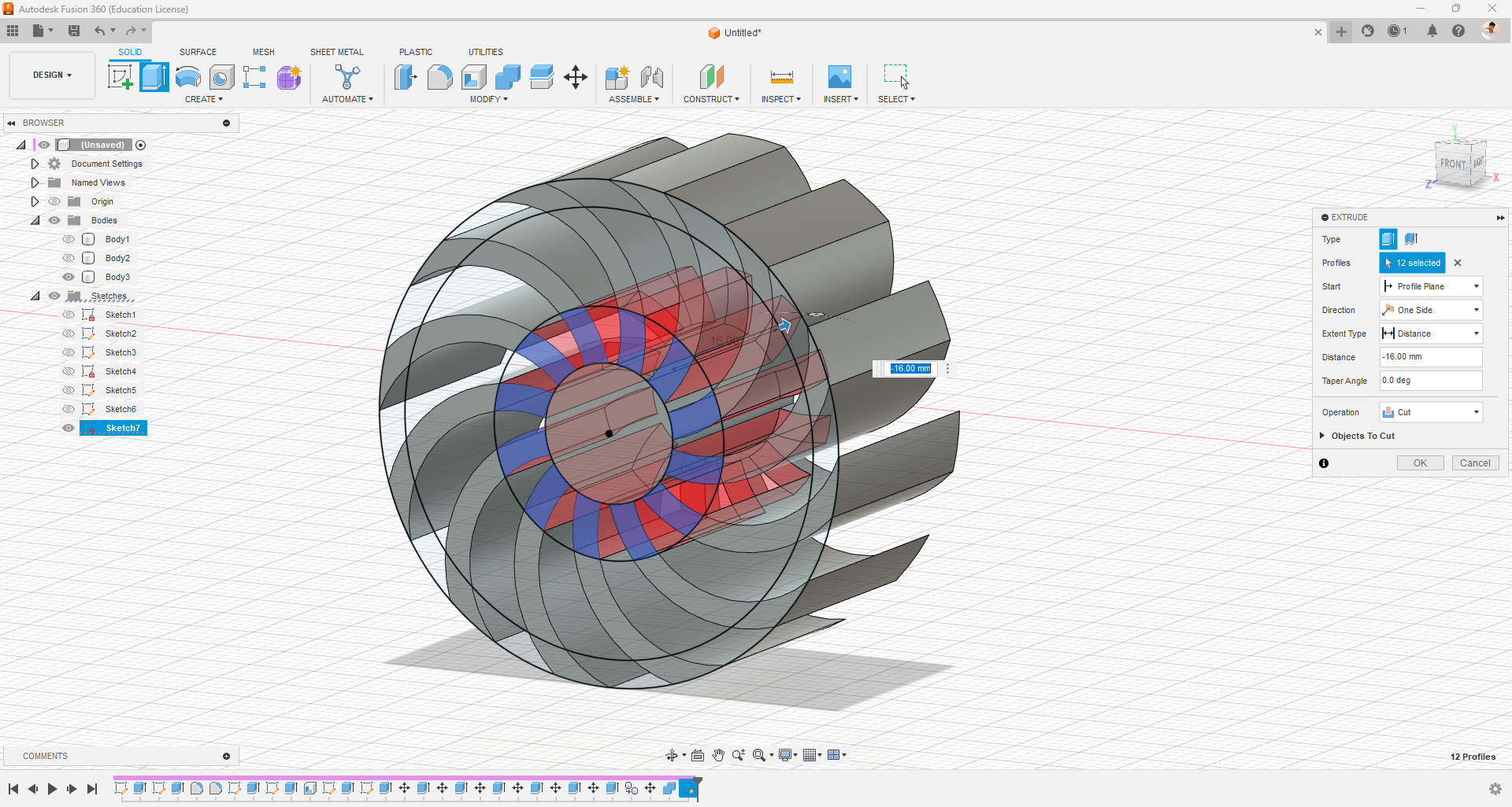
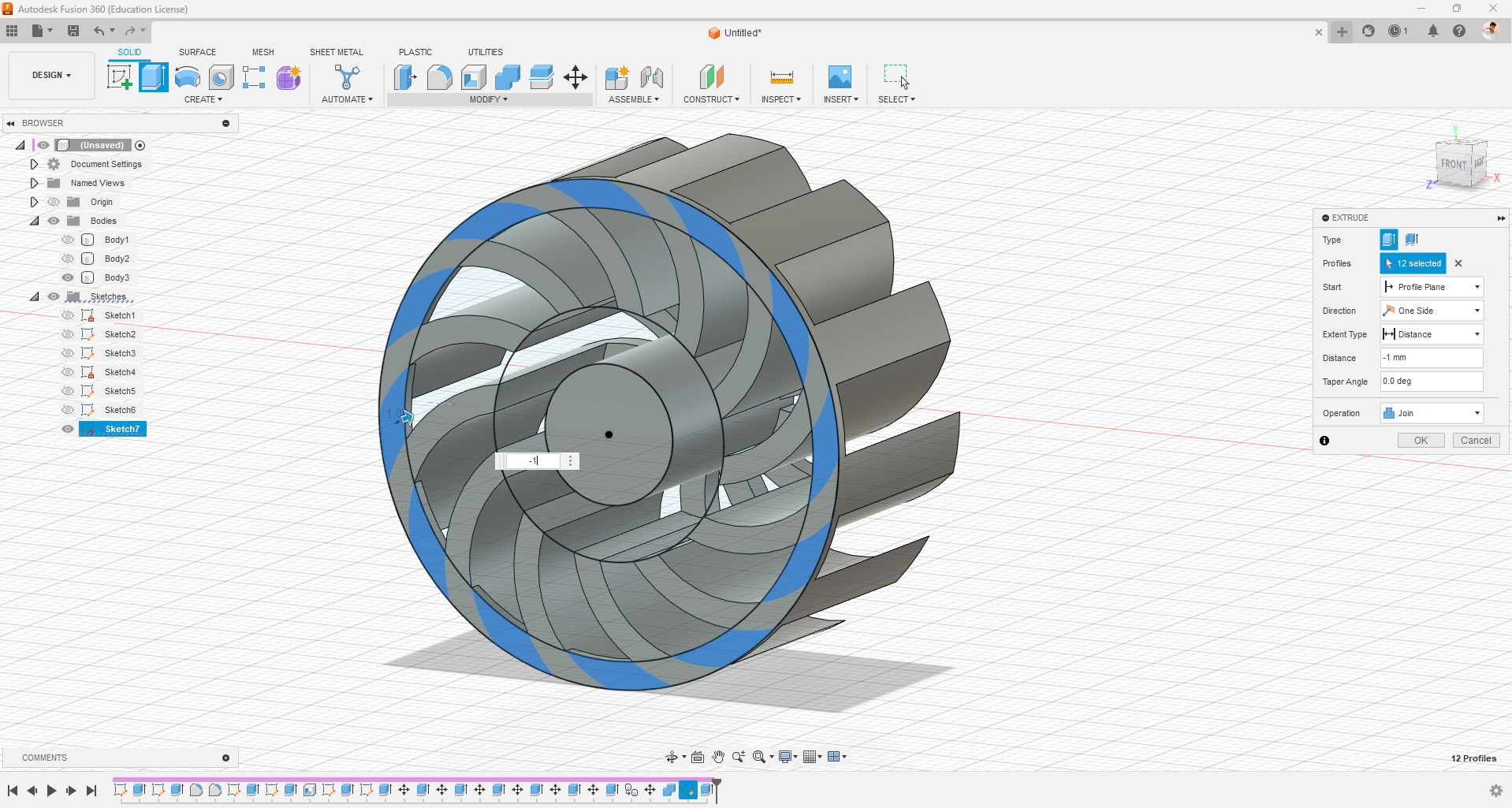
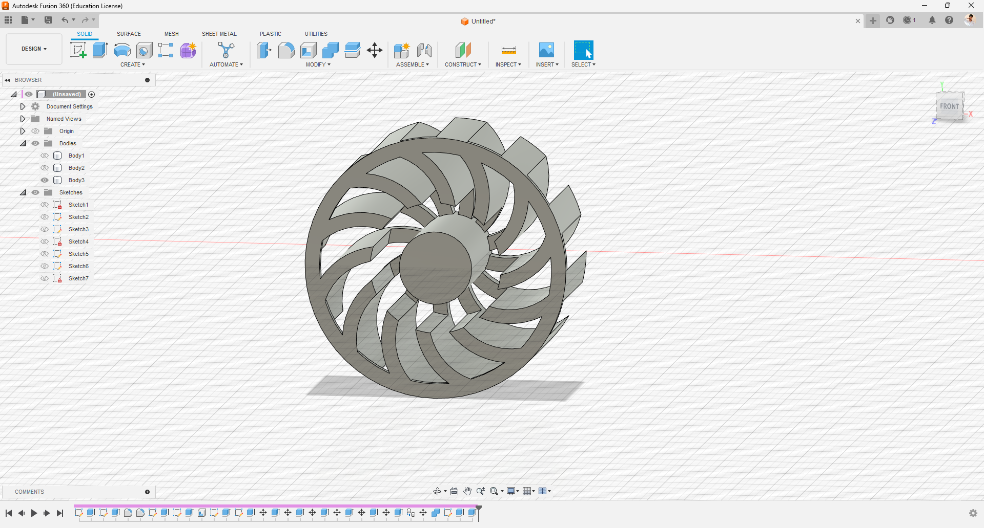
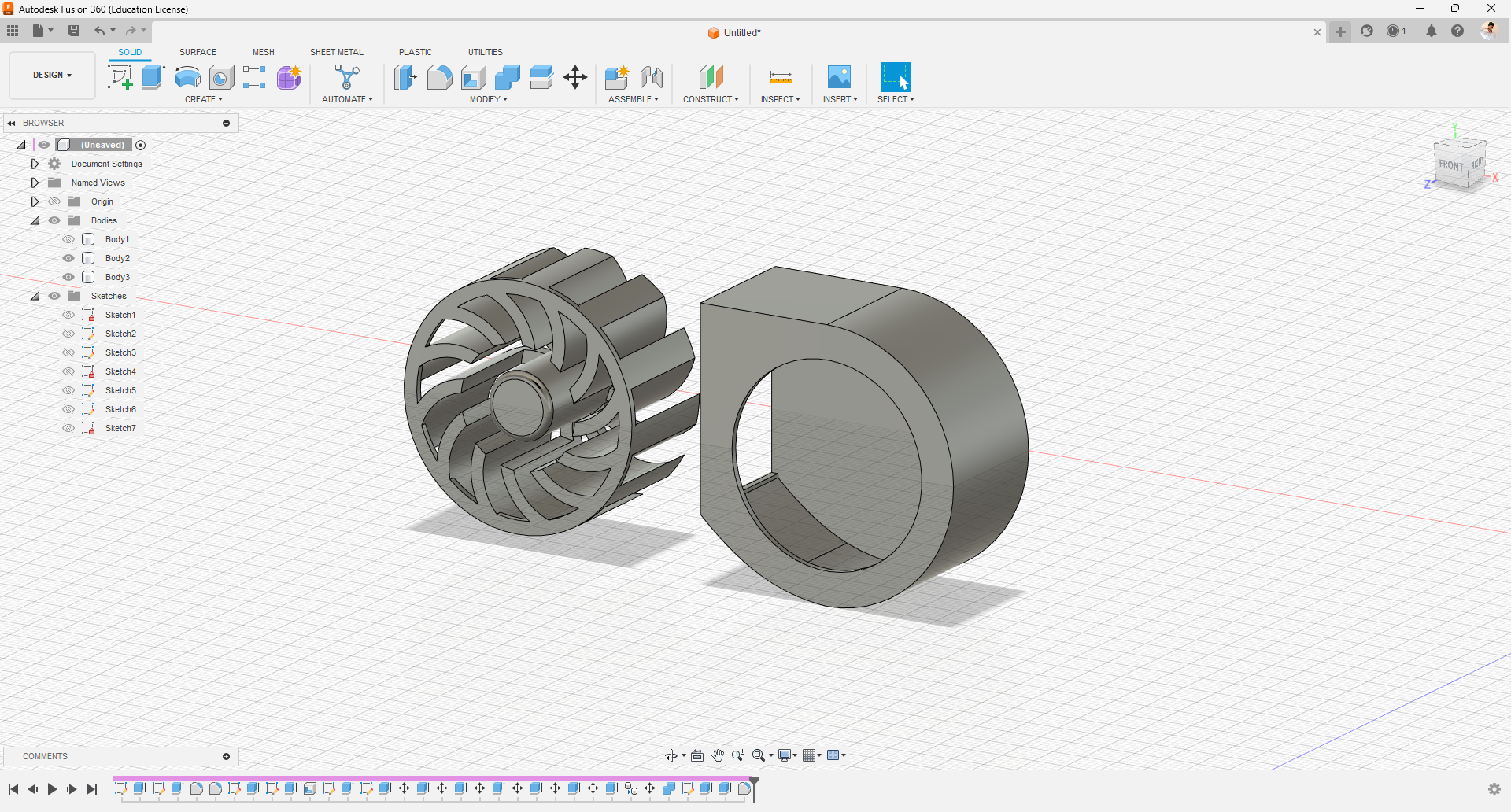
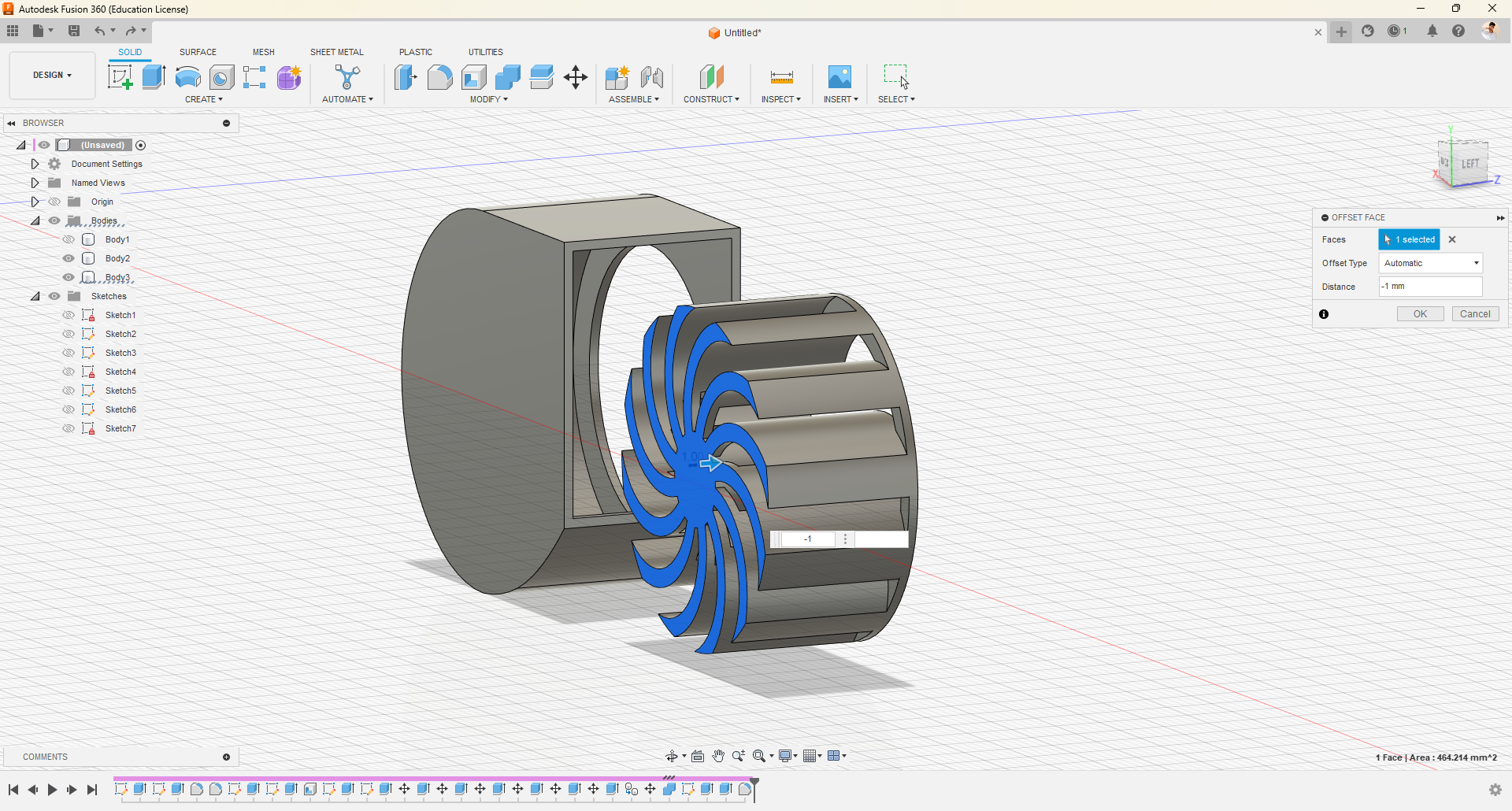
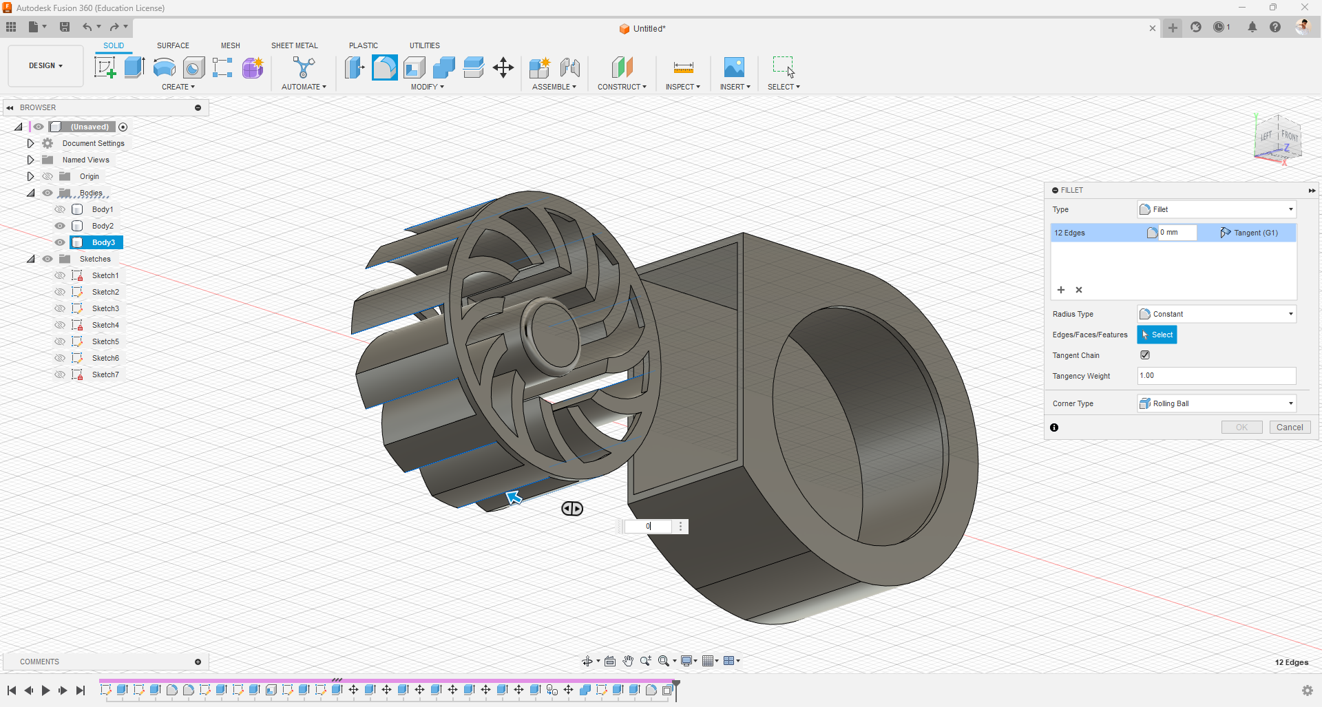
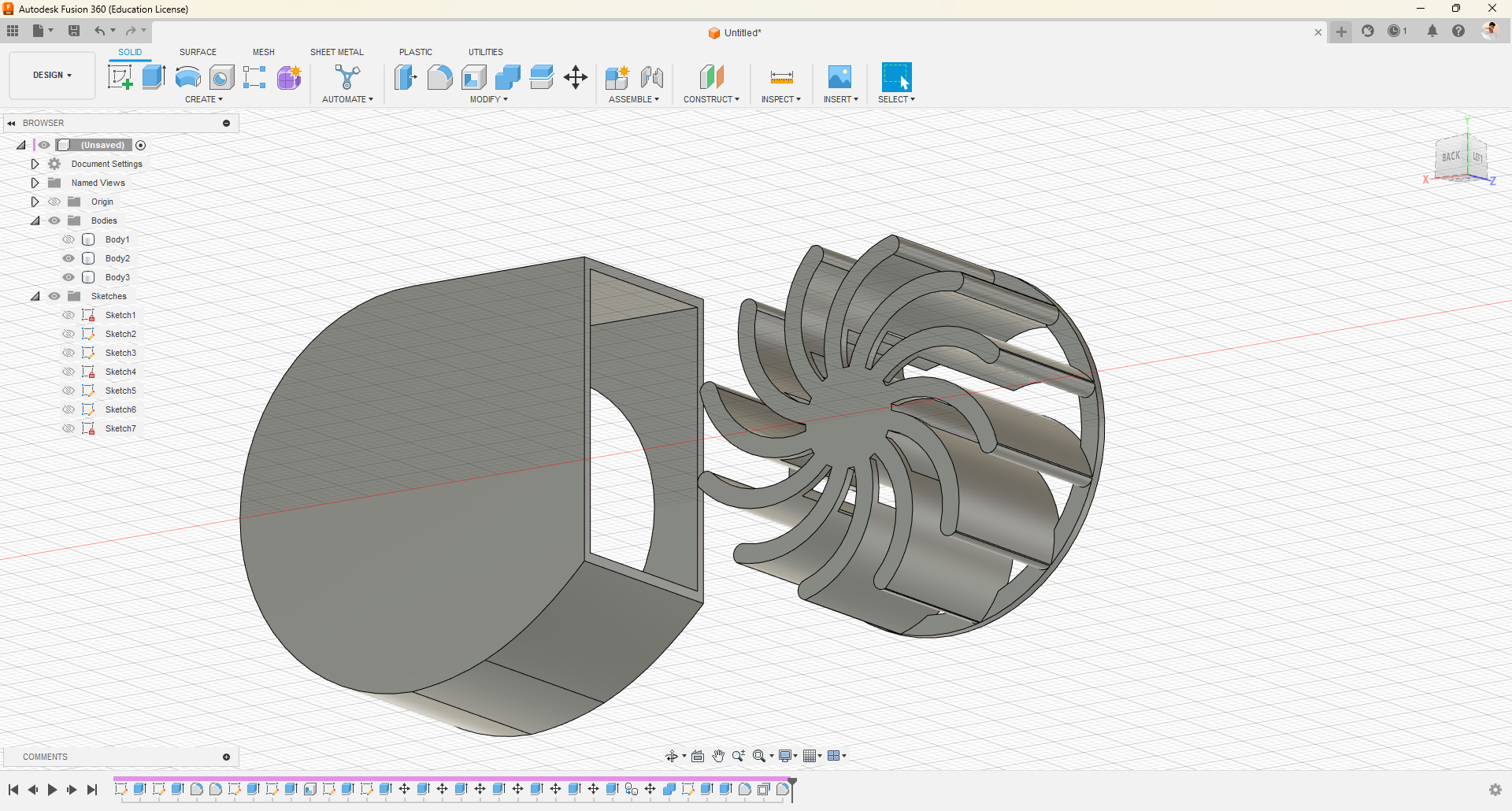
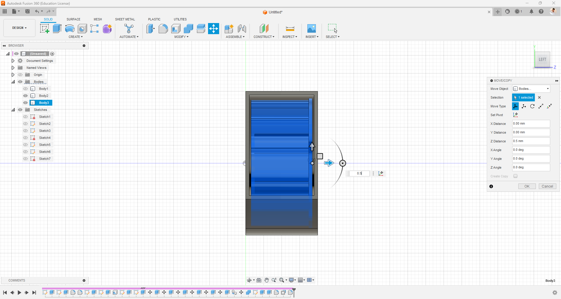
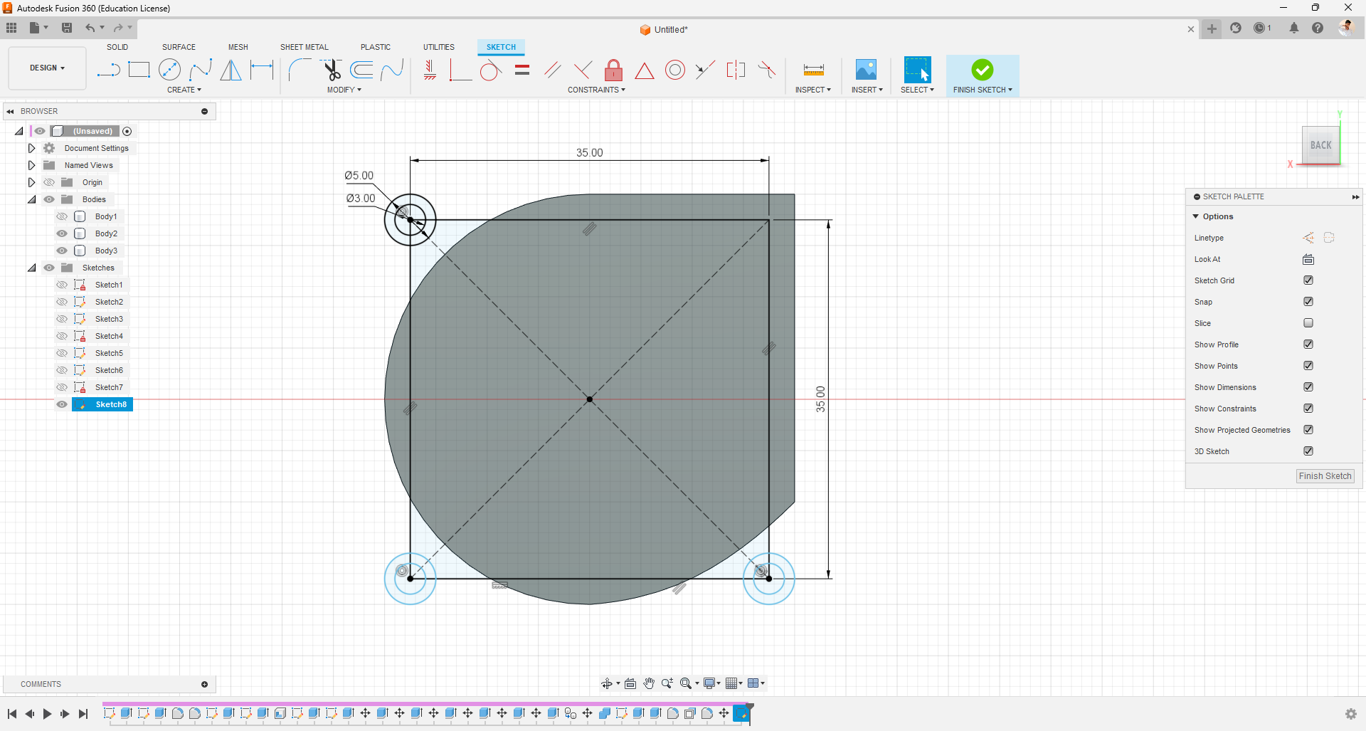
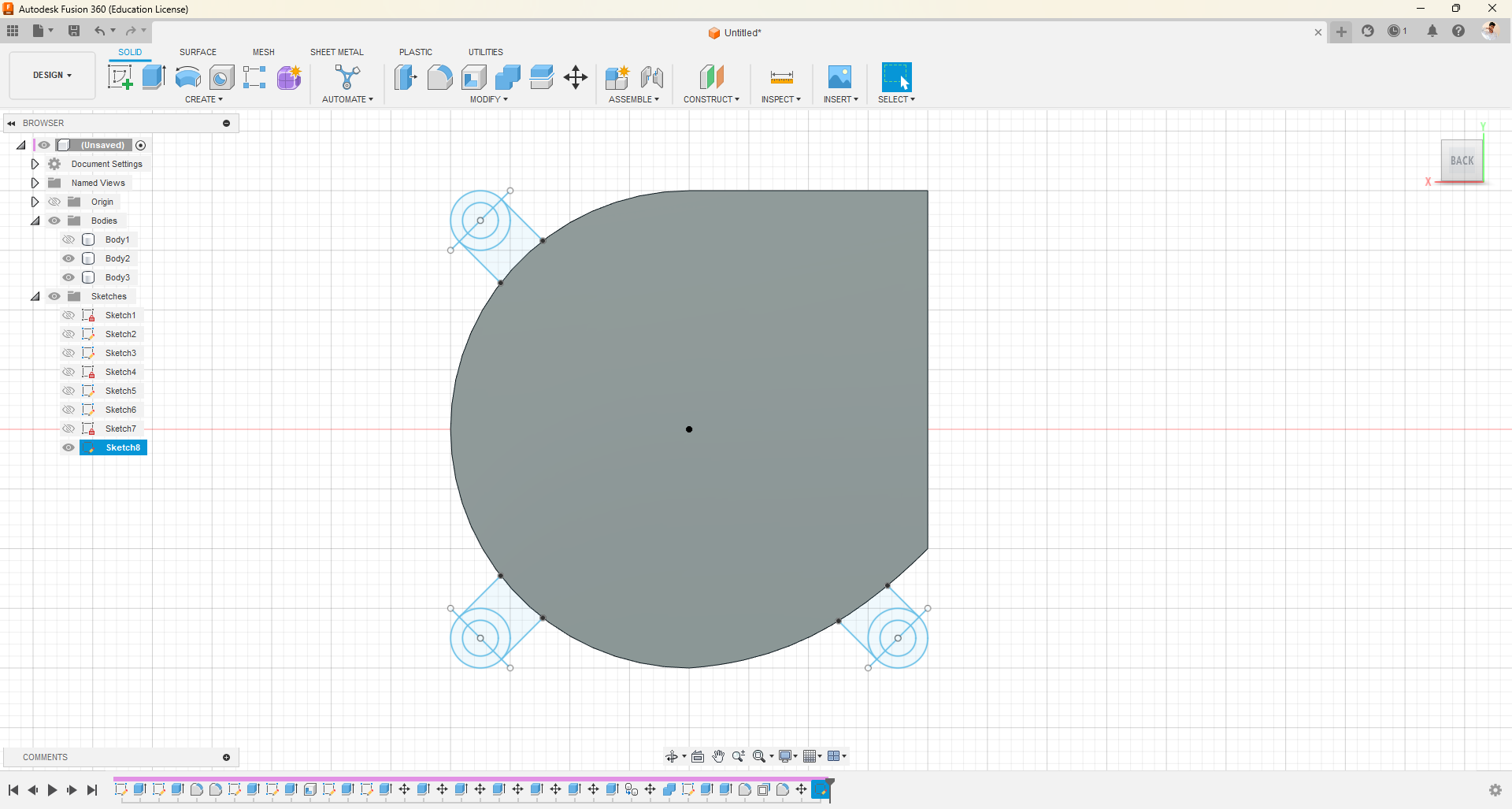
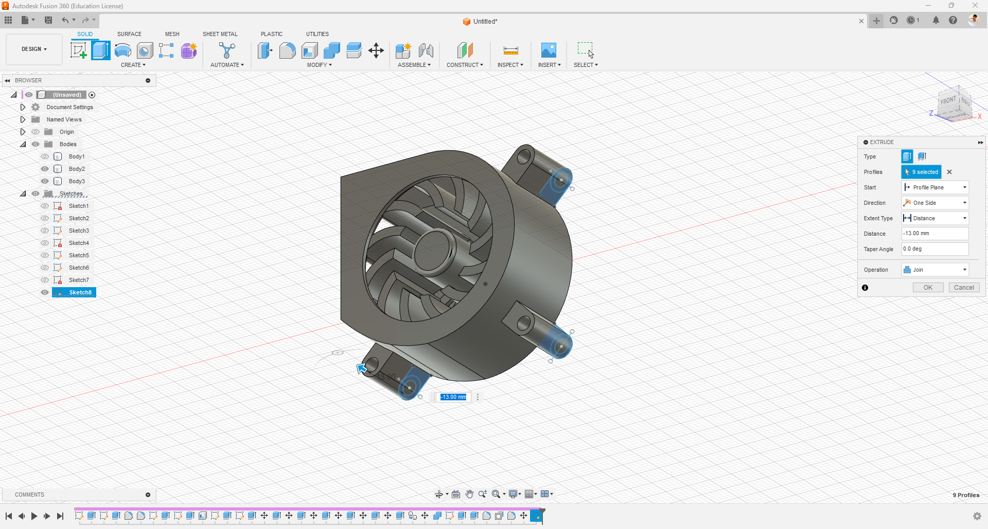
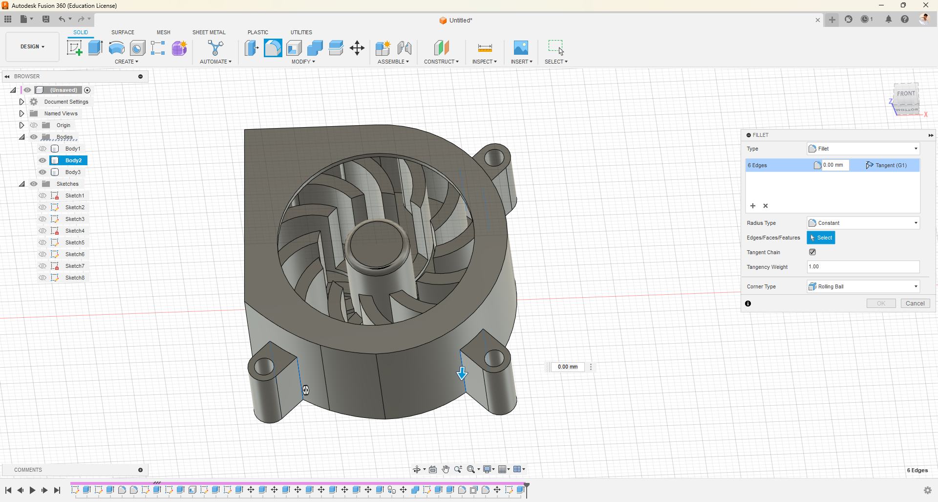
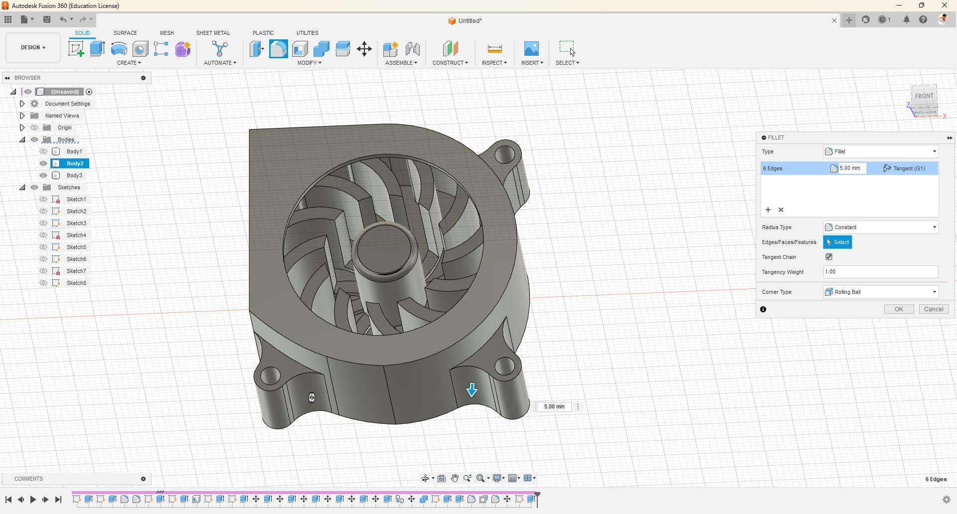
- First, draw the basic 2D drawing and use the press-pull option to create a single blade and the central shaft. Click on the eye icon of the most recent sketch in the left Sketches folder to view it.
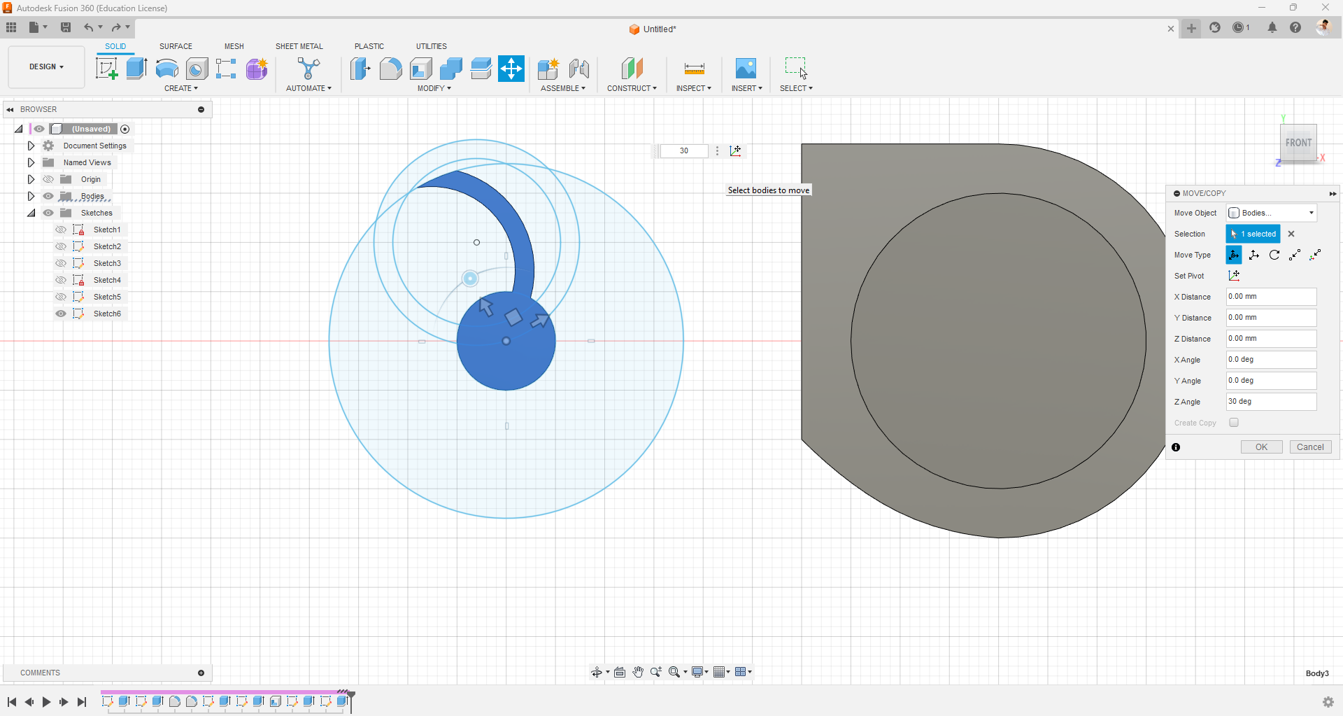
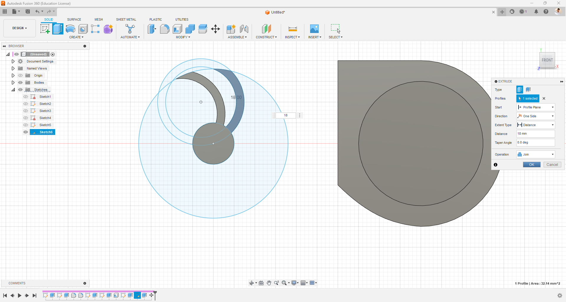
- Then, use the move/copy option (right-click -> move/copy) to rotate the object by 30 degrees from the center and pull the blade's drawing surface by selecting the operation as join.
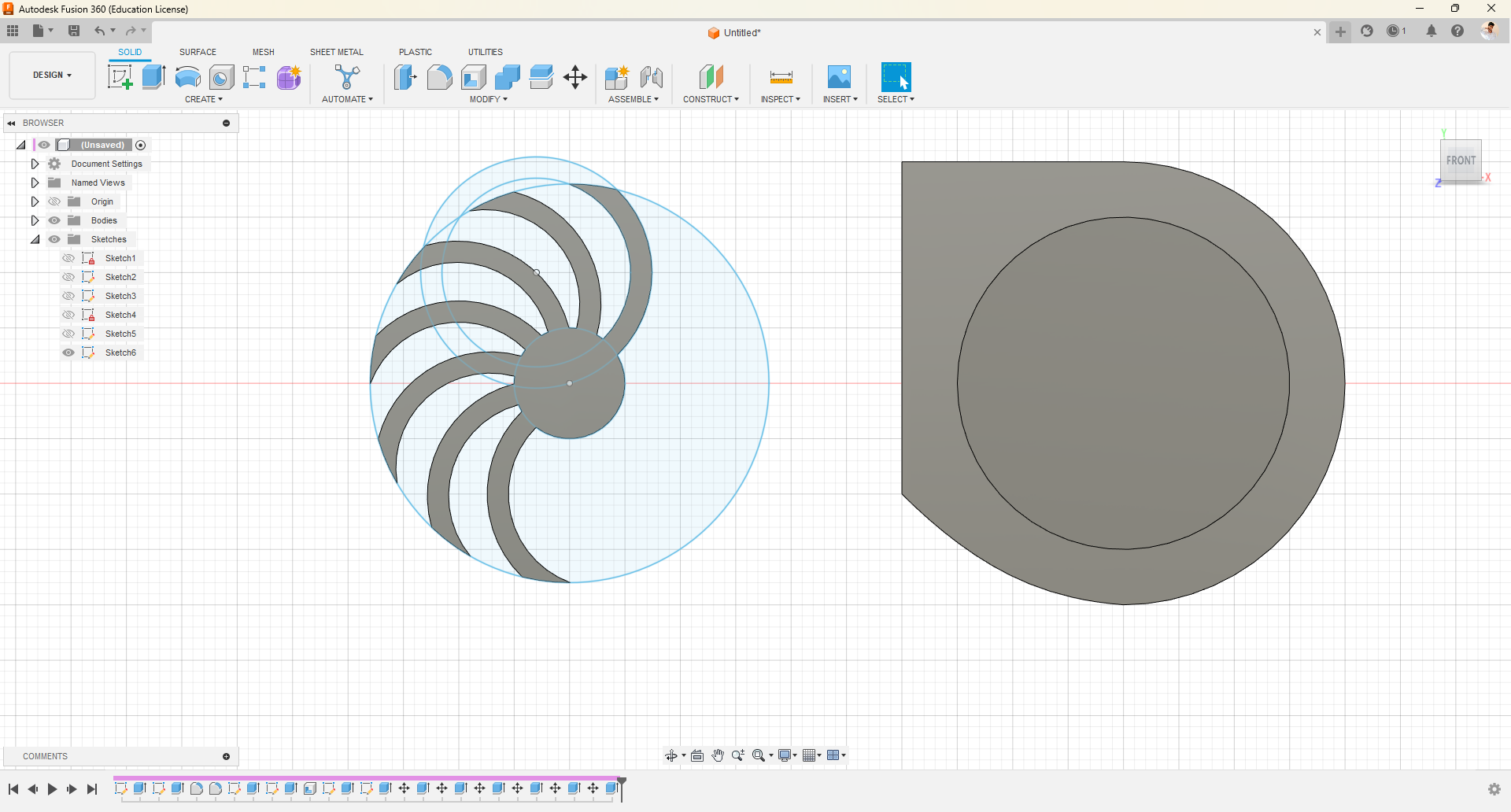
- Repeat the same steps for the other half, using the move/copy option to mirror it.
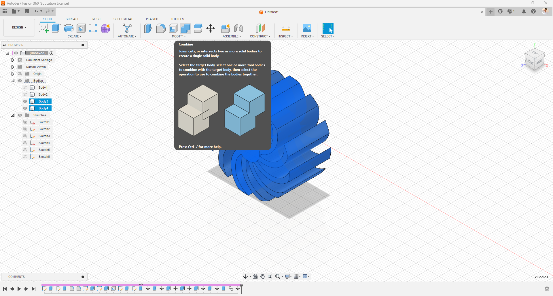
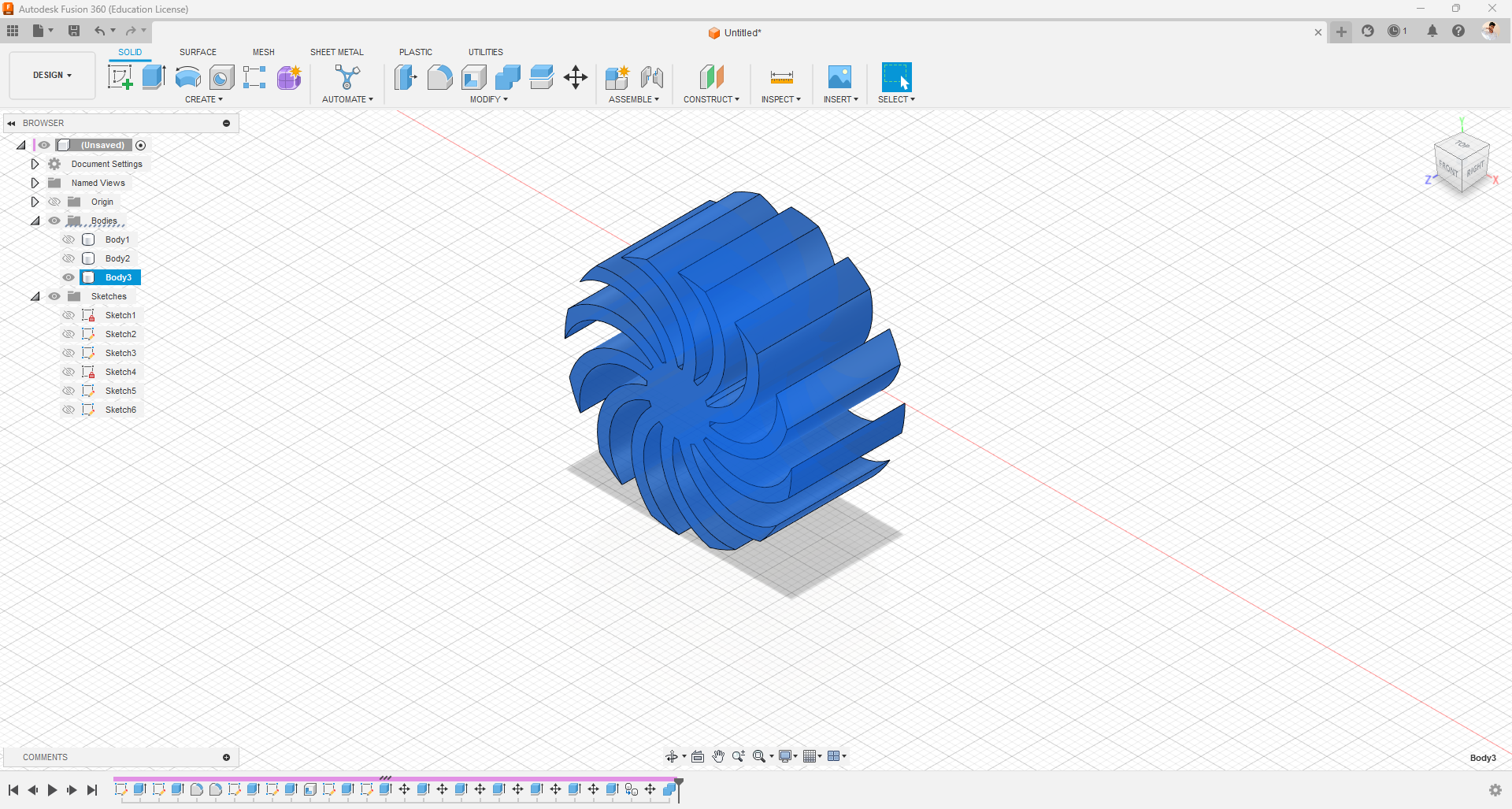
- Currently, we have two separate bodies of the propeller, which can be combined using the combine option.
- After the basic propeller is ready, make a few aesthetic changes using the draw and press-pull options.
- Once satisfied with the propeller, move the propeller body inside the fan cover.
- Then I designed this structures for screwing the fan.
Fusion 360 Materials & Colors
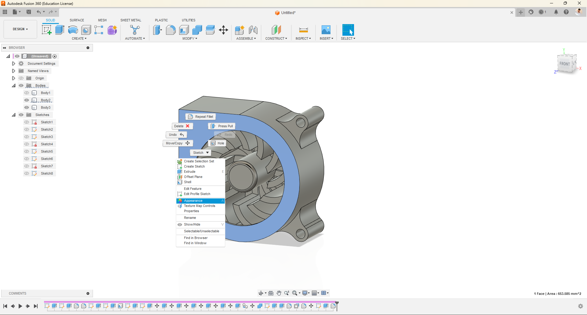
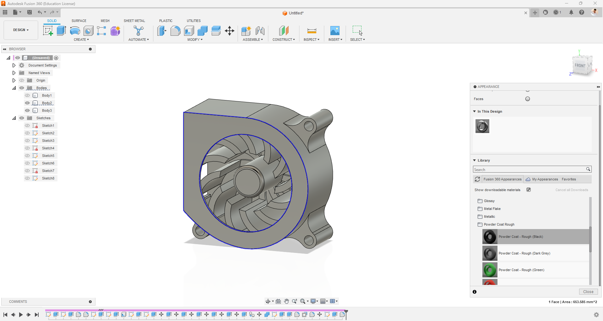
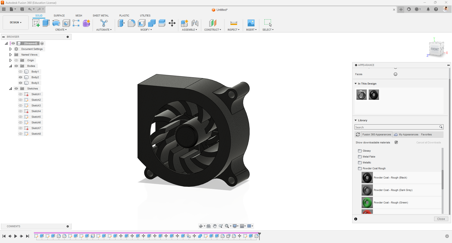
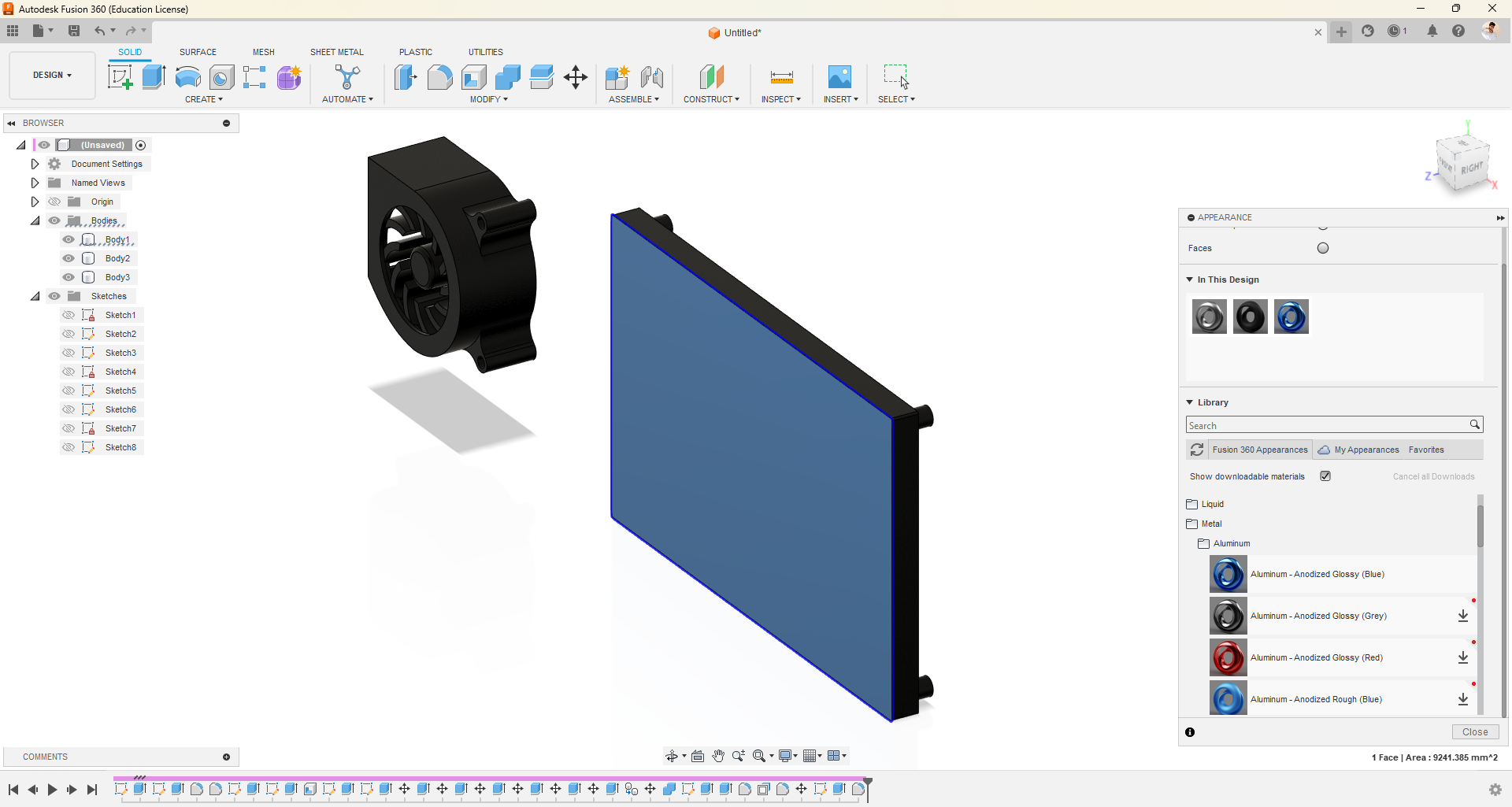
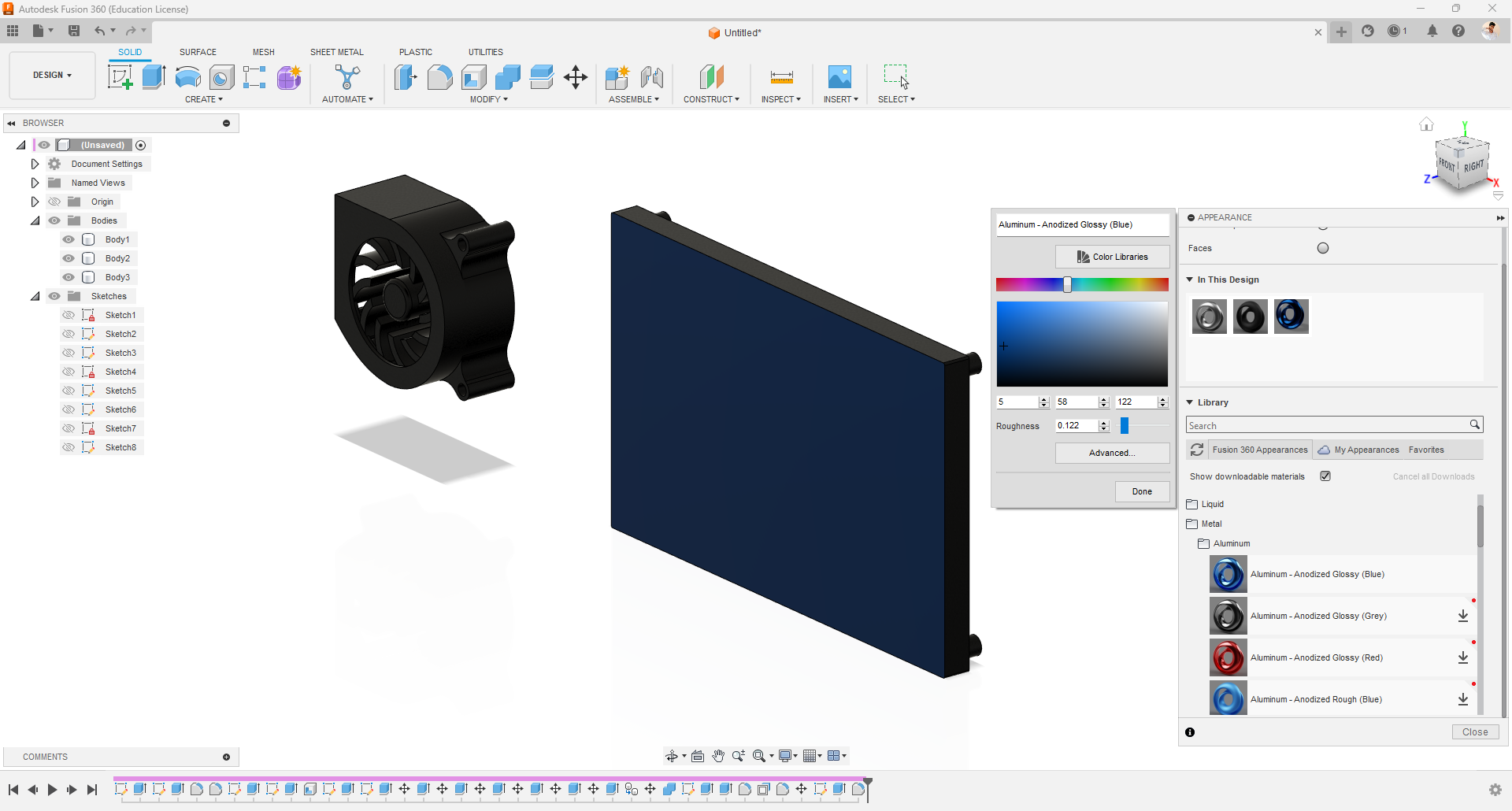
- By right-clicking, we can access the Appearance option, where we can find various types of materials and colors. We can either use the pre-downloaded default options or click on the download icon to acquire new ones.
- To apply a color or material to an object, simply drag and drop it onto the object.
- If we double-click on the applied material, we can adjust properties such as color, texture, and more to achieve the desired results.
- Instead of applying the material to the entire body, we can select a specific surface and apply the material to that particular area.
- Experimenting with these options will help us achieve satisfactory outcomes.
Importing Raspberry Pi 3D Model(STEP File)
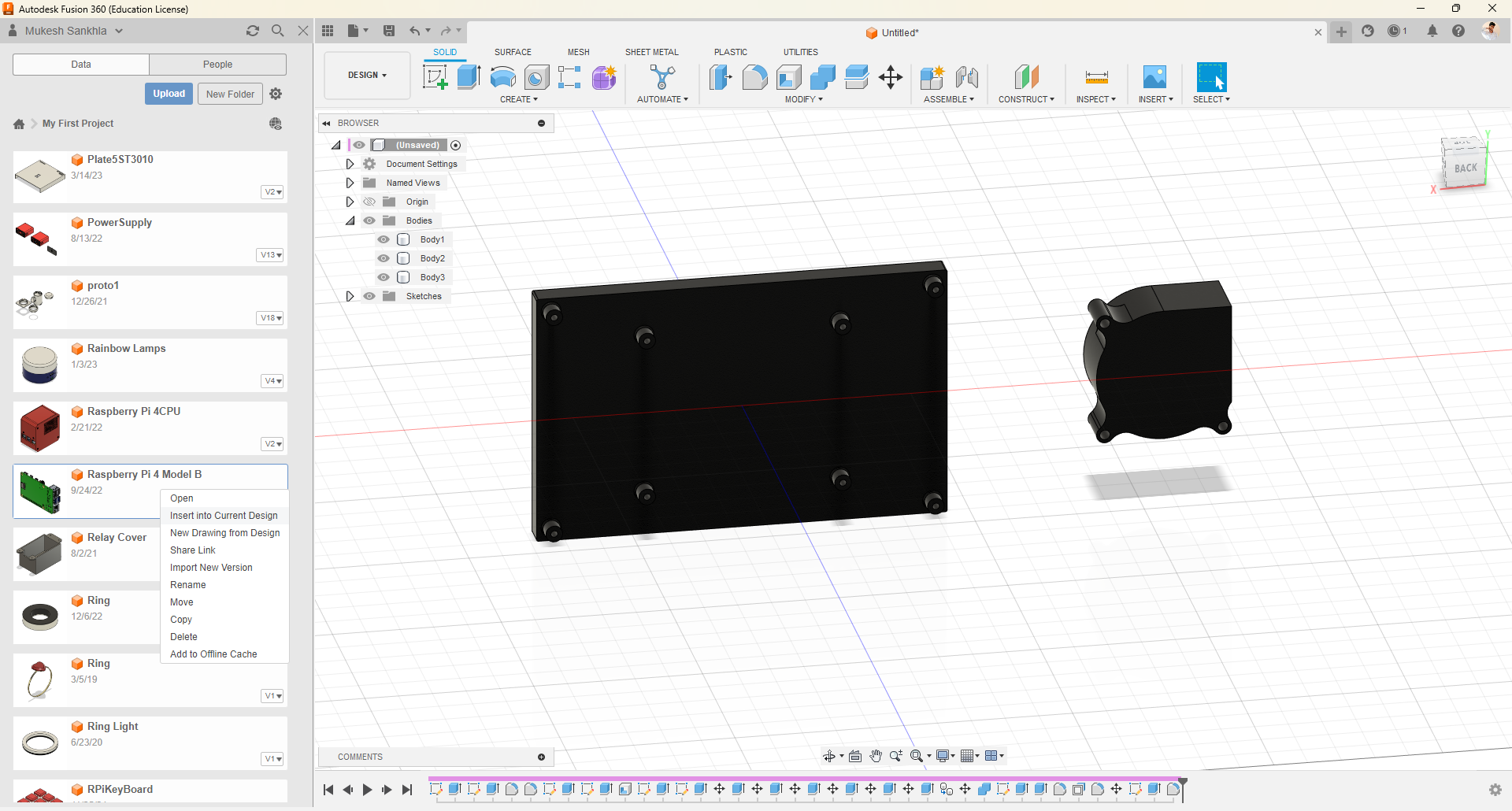
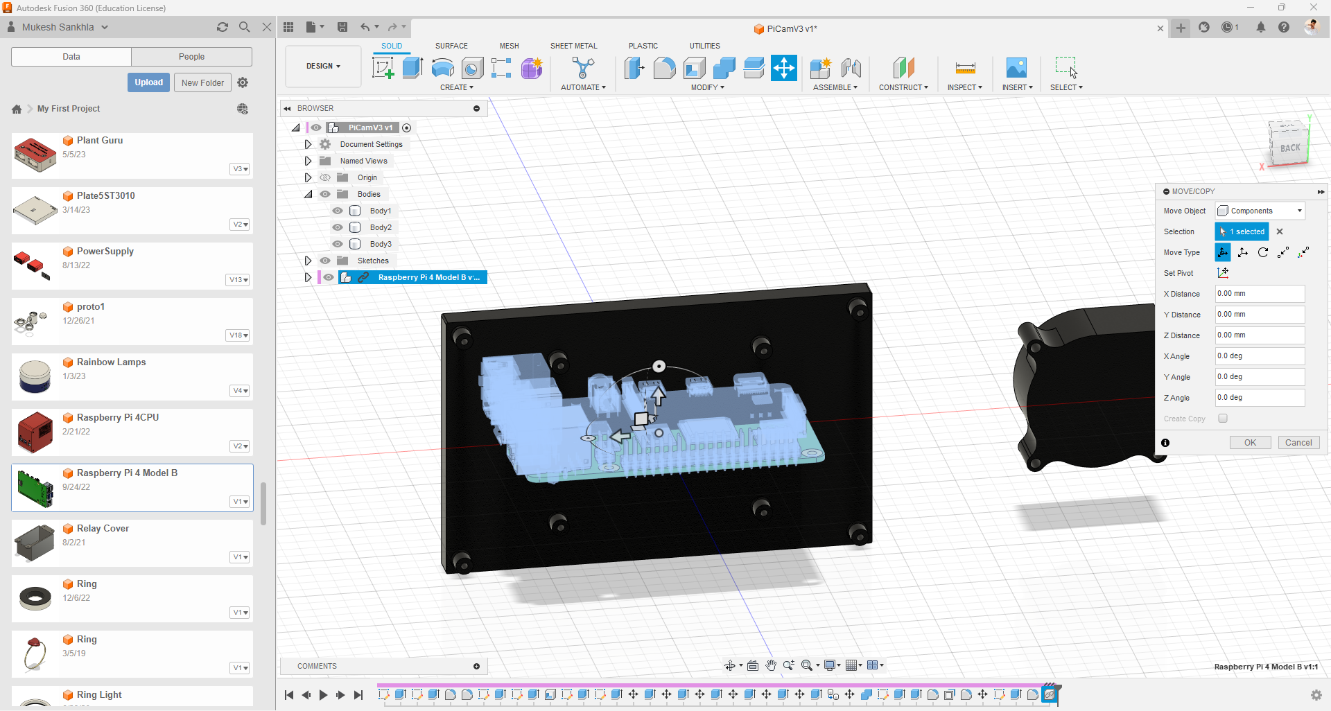
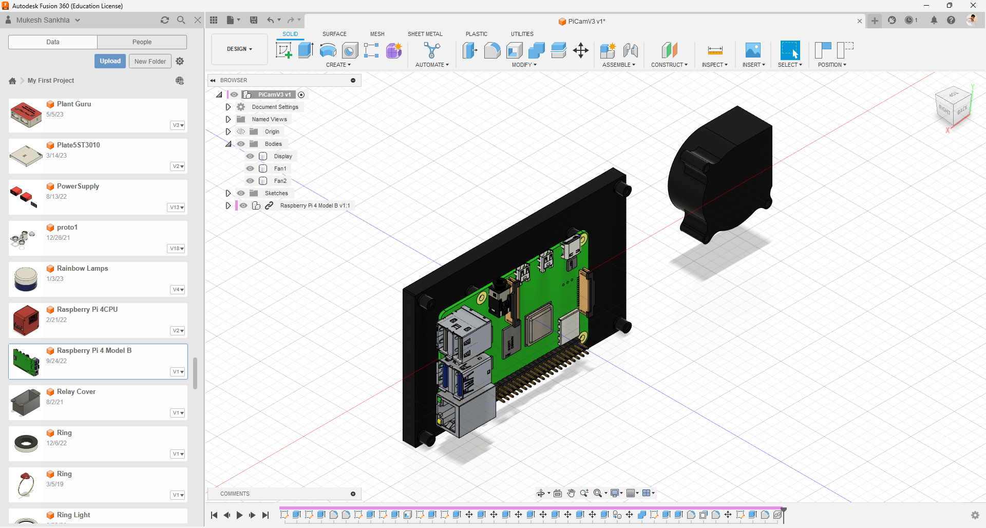
- I have already uploaded the STEP file of the Raspberry Pi to my Fusion360 directory. If you have found any other 3D model (STEP file), please do the same.
- Now, save the current project, right-click on the file, and select the "Insert into current design" option to position the imported object.
Importing 3D Mesh Models
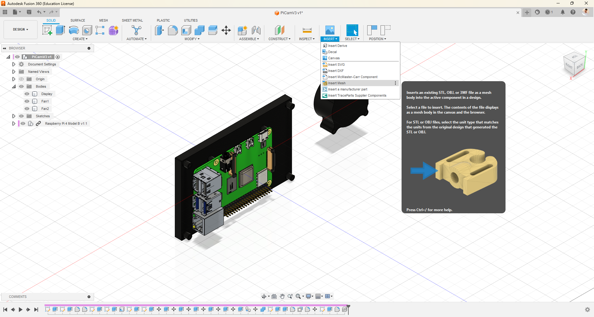
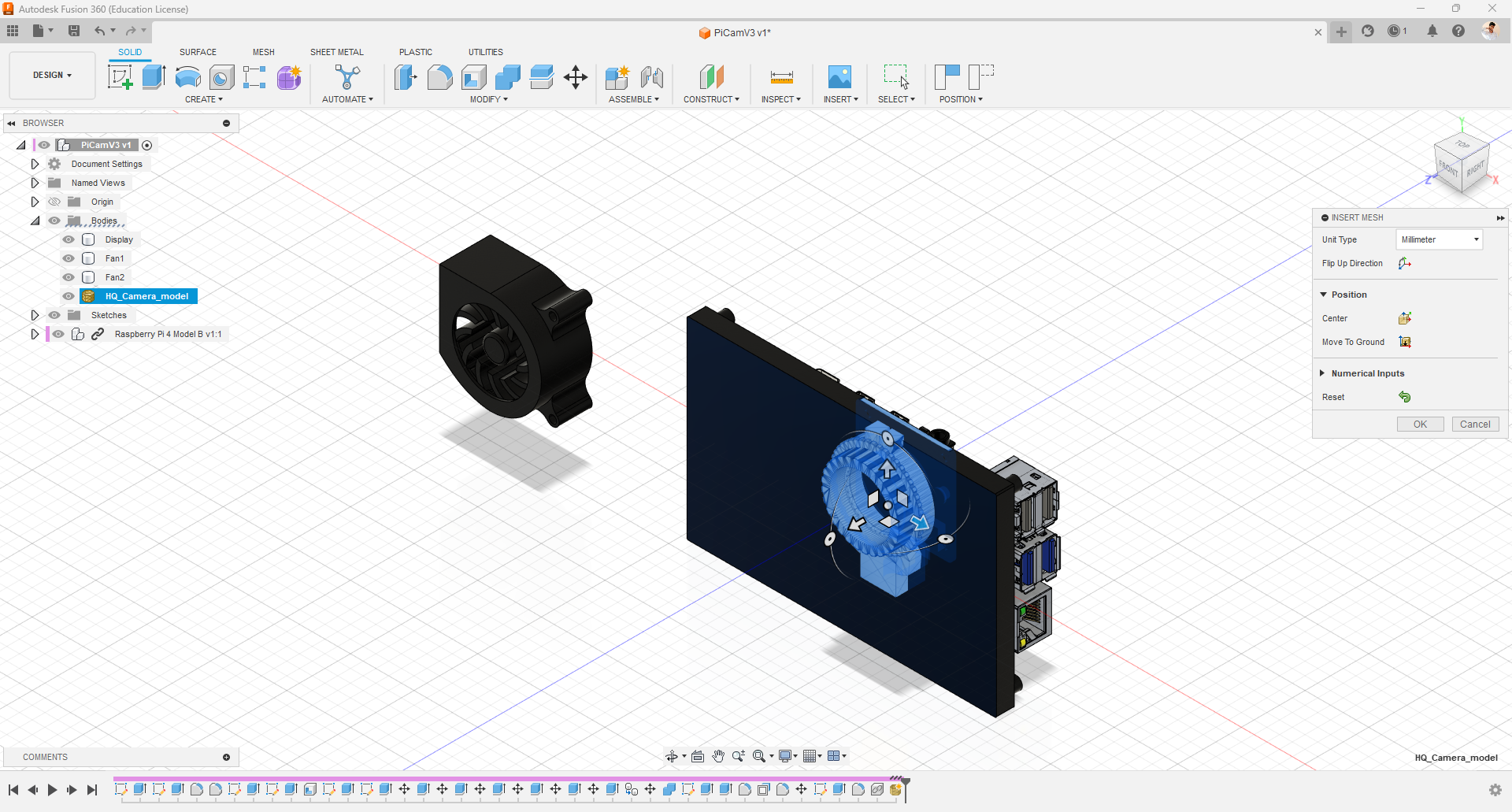
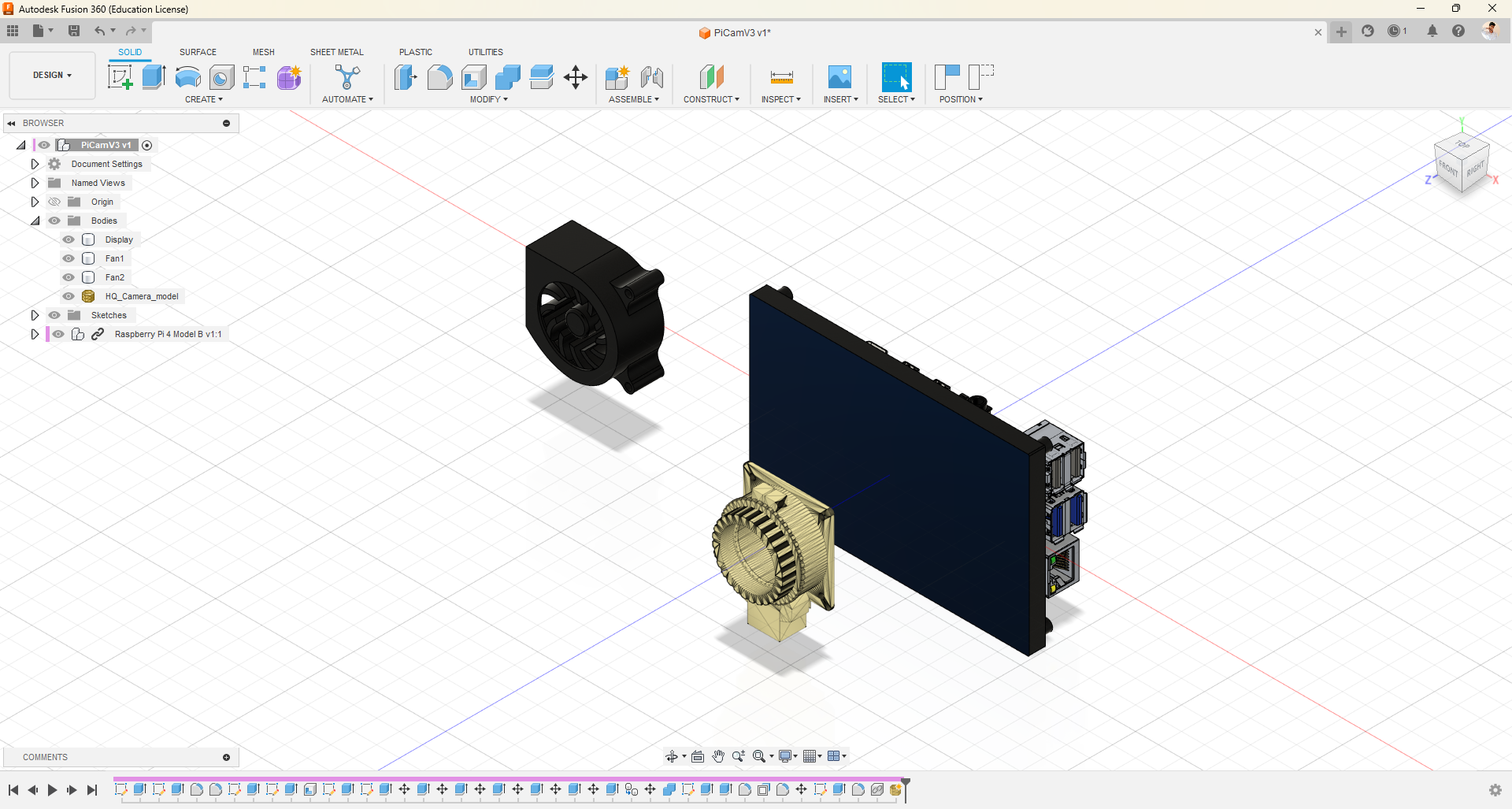
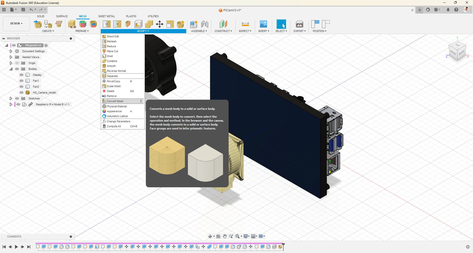
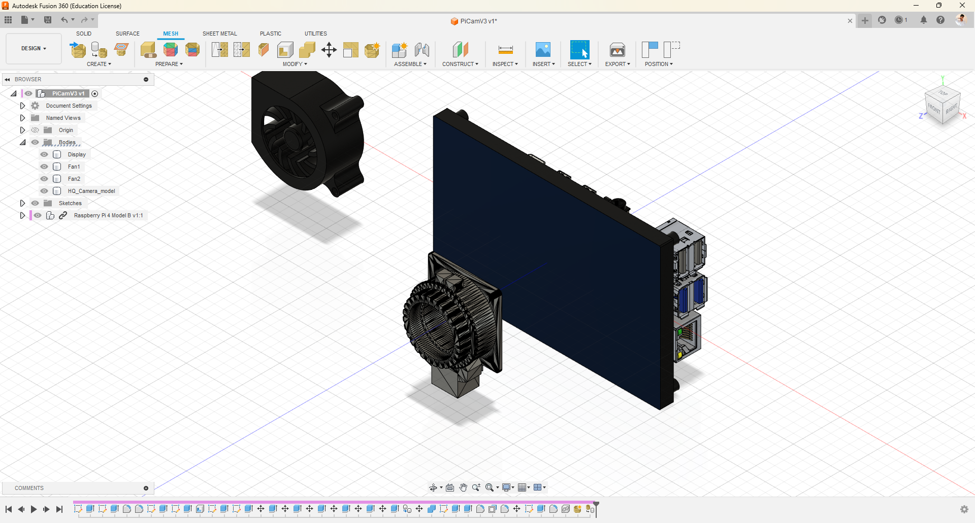
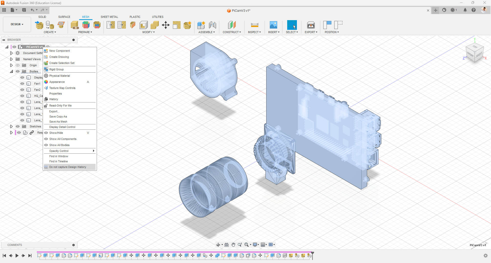
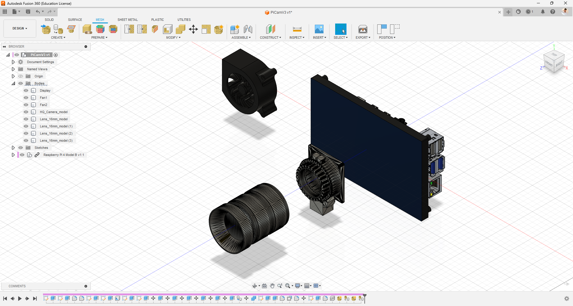
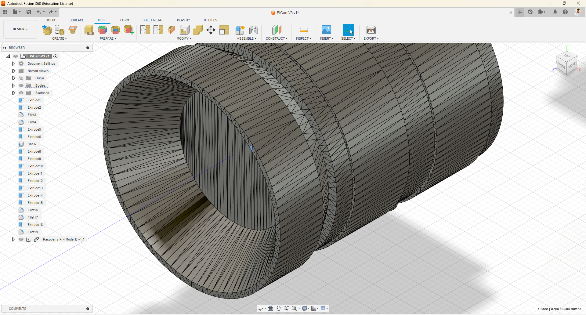
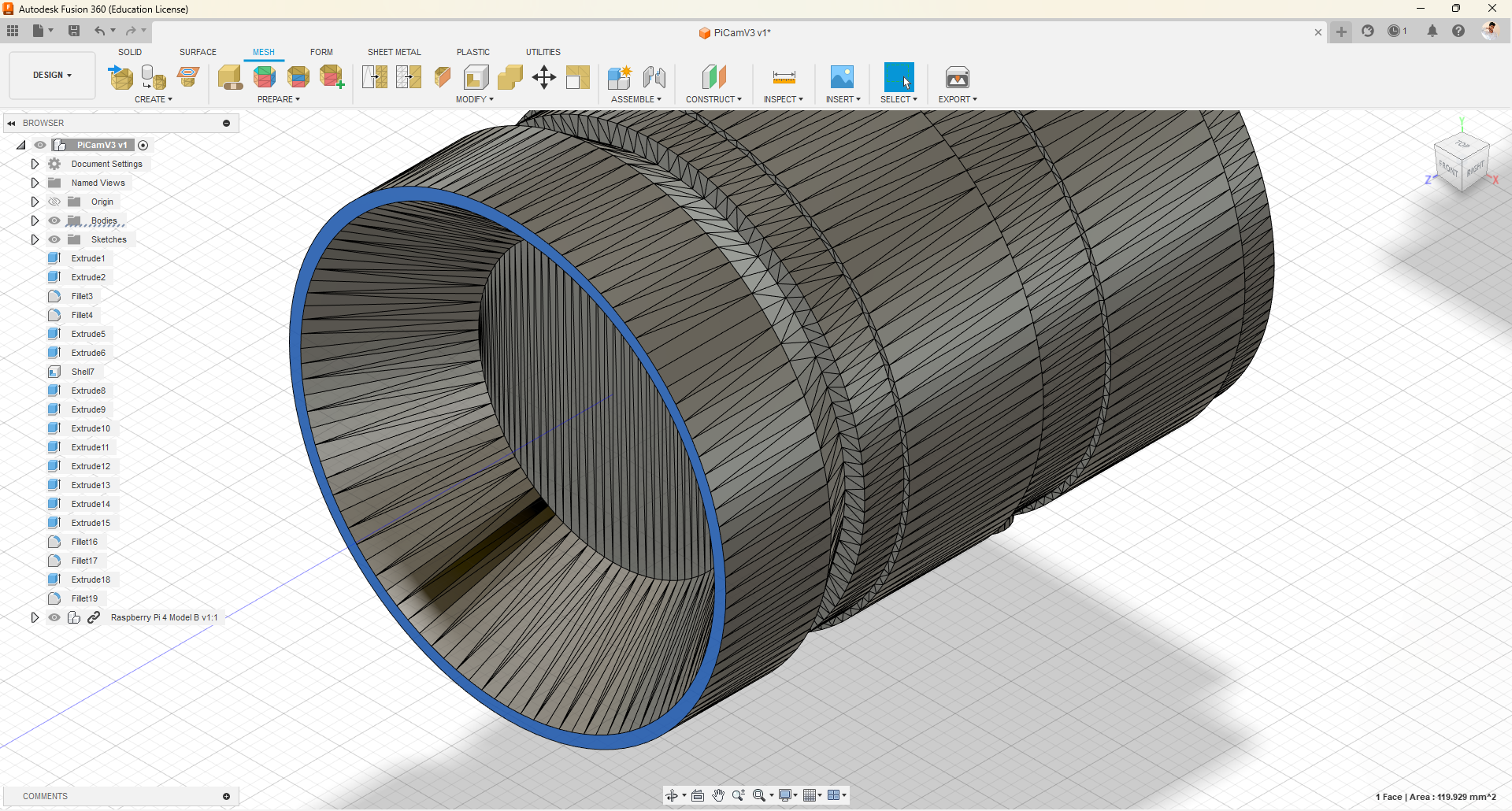
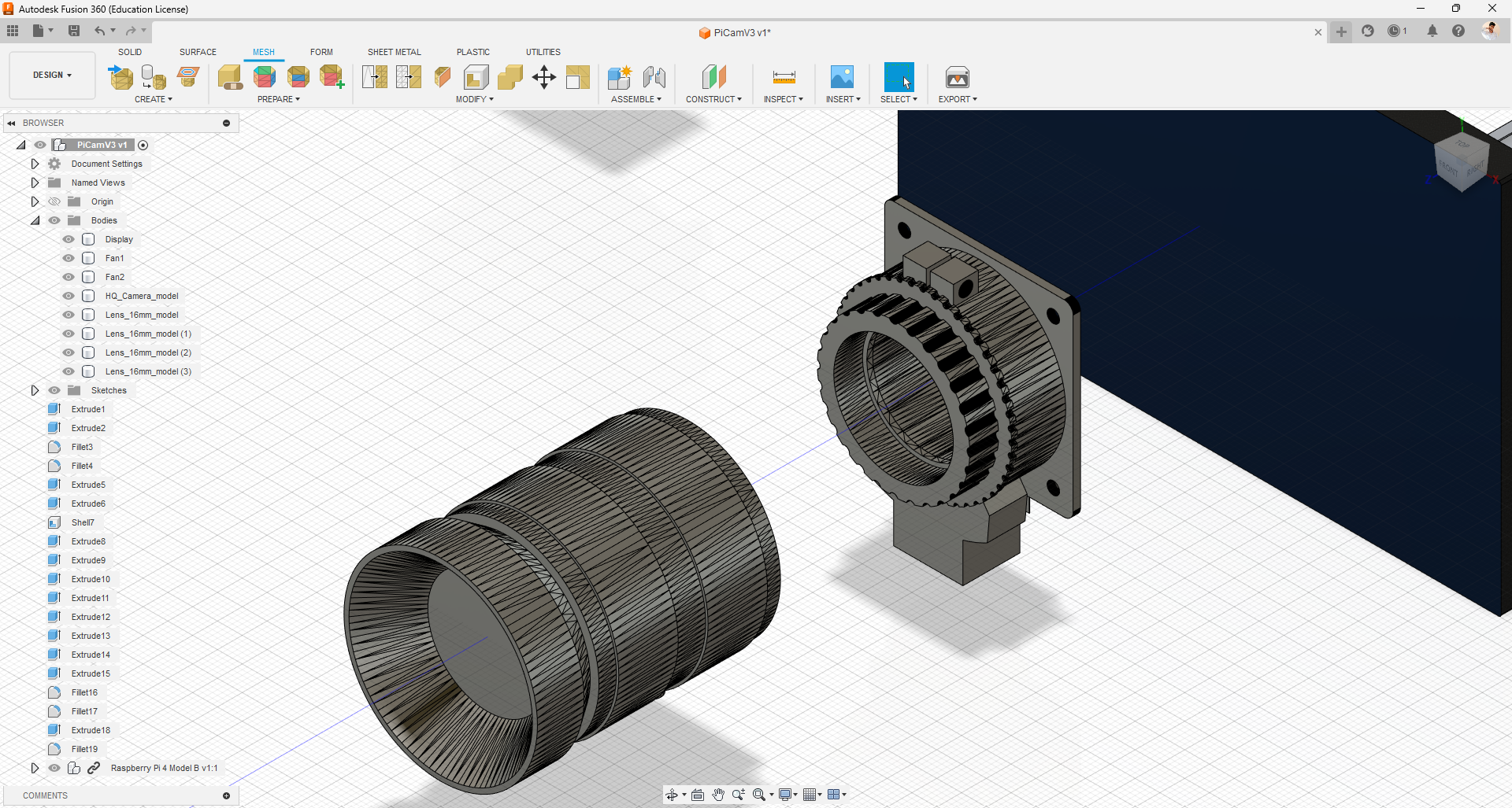
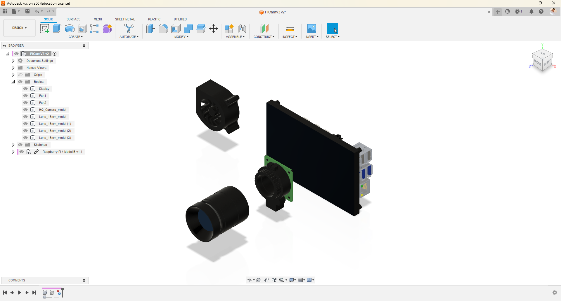
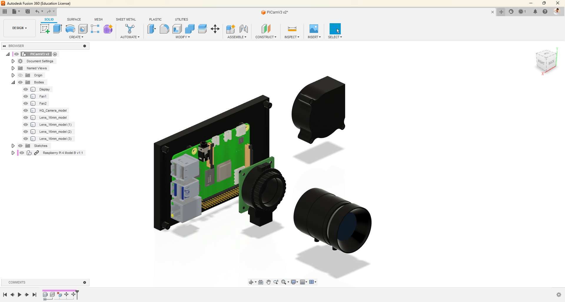
To incorporate a mesh object into our design, we need to import the mesh file. I have a camera module and its lens as a mesh file that I want to use in this design. To do this, follow these steps:
- Insert the mesh file and position it in the desired location.
- Click on the "Mesh" option in the top bar to go to the Mesh section.
- In the Mesh section, you will find a feature to convert the mesh body to a solid body. Use this feature.
- Right-click on the main folder on the left and select the "Do Not Capture Design History" option.
- We are doing this because the mesh solid bodies have many triangular patterns that need to be cleaned, and capturing them in the design history would add unnecessary steps.
- Select the triangles on the plane surfaces and delete them.
- Note that this process may take some time to complete, so please be patient.
- It is important to only delete triangular meshes from flat surfaces to avoid deforming the shape of the object.
- After completing the previous steps, apply colors and materials to the objects.
We are almost ready to start designing the camera enclosure, but first, let's perform these necessary steps.
Design Screws
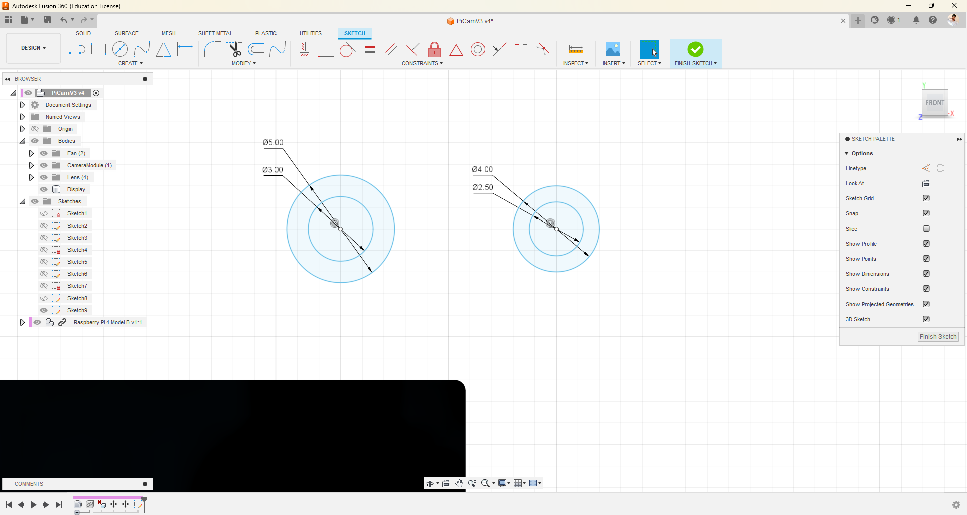
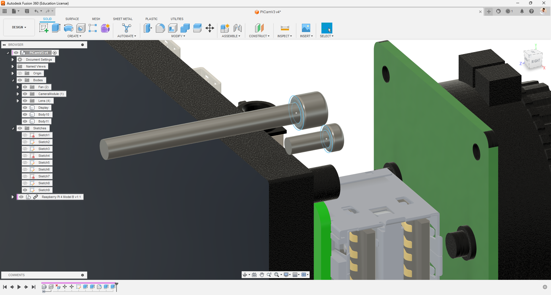
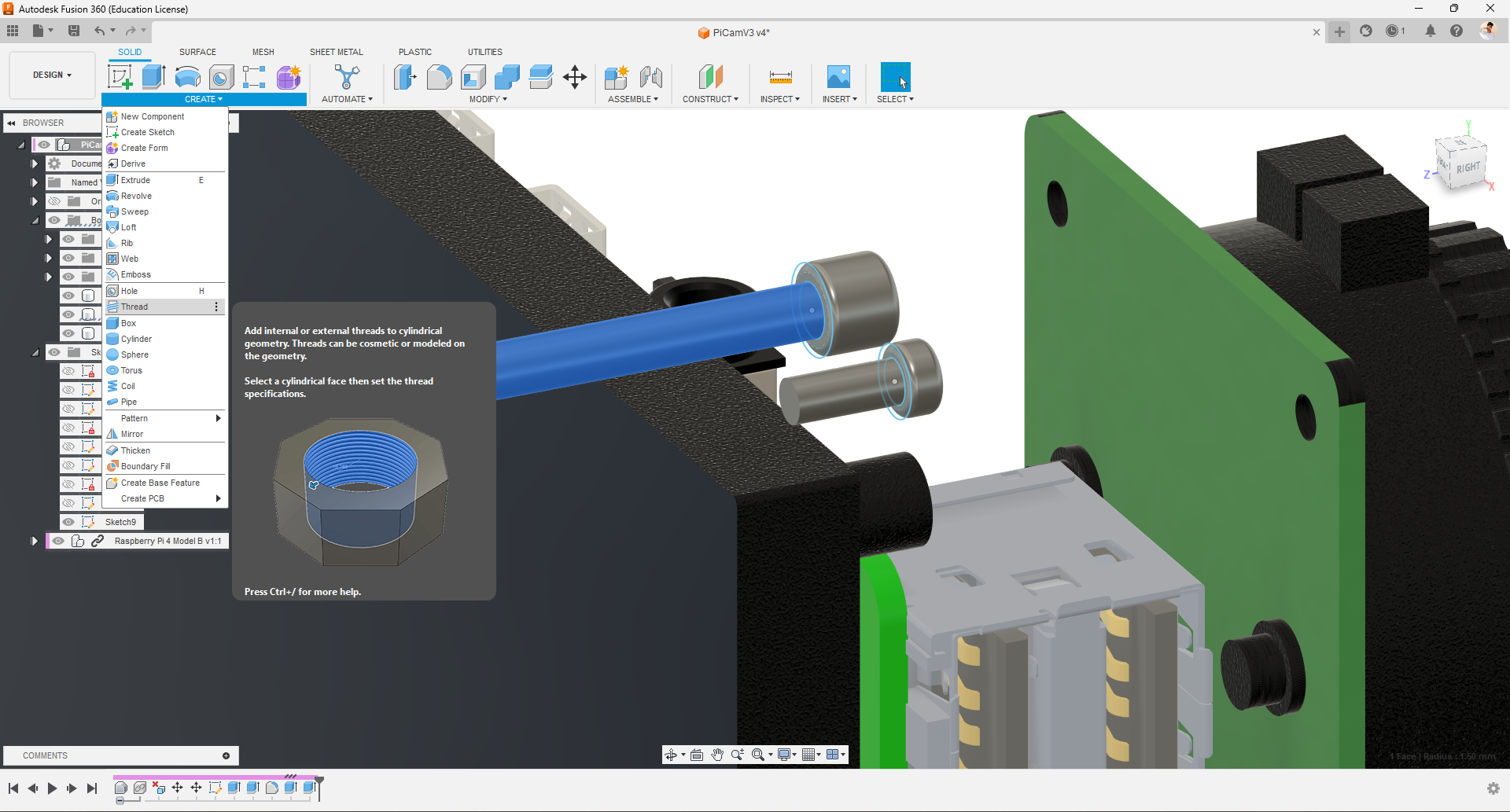
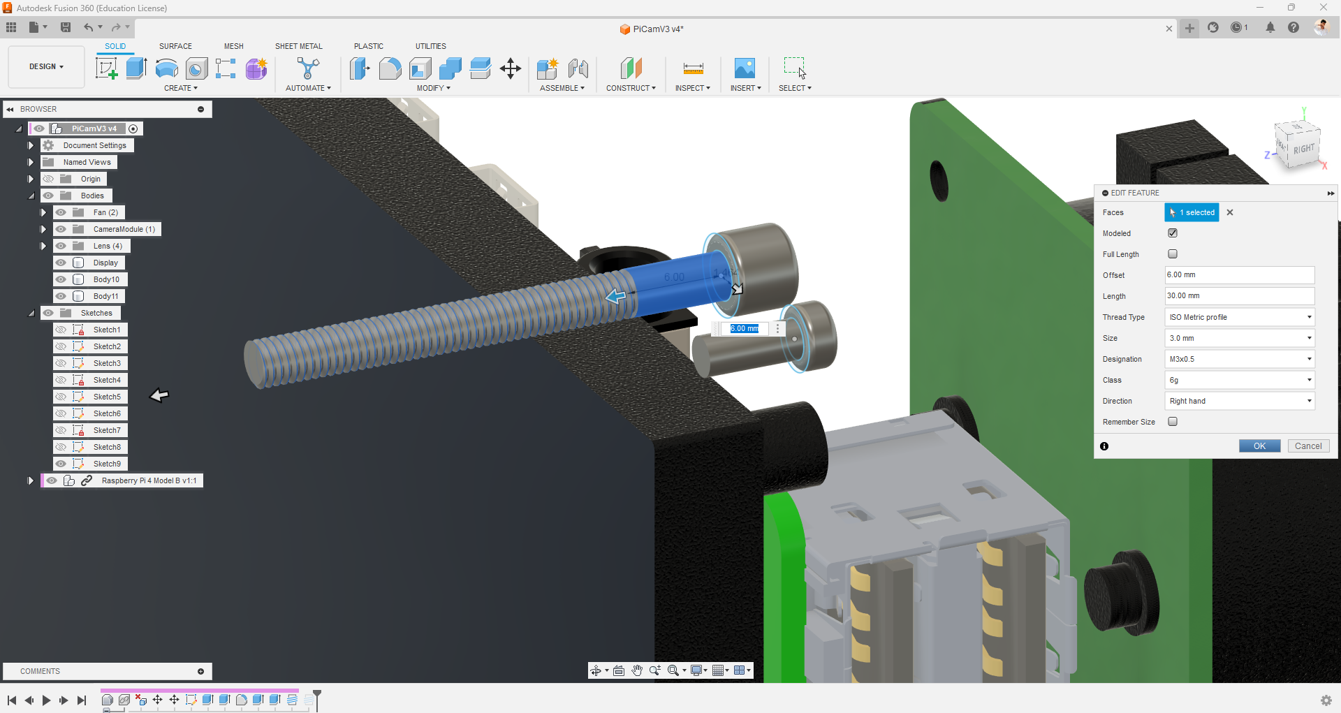
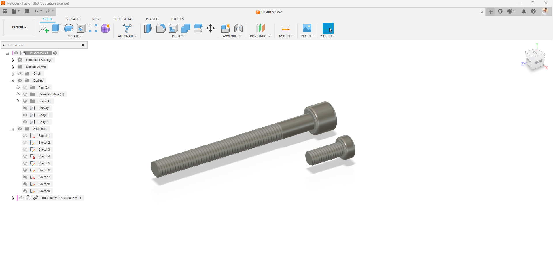
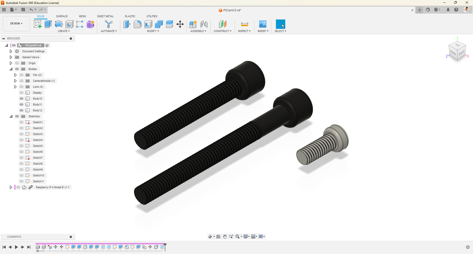
- Using the "Create Sketch" and "Press Pull" tools, I created two cylindrical shapes resembling screws.
- I applied a fillet to round the edges on the top portion.
- Next, I utilized the "Thread" option to add screw threads, making sure to check the "Modeled" option and experiment with the "Full Length" option.
- With these steps, I successfully created three screws of different sizes: 3x30mm, 3x20mm, and 2.5x6mm.
- I can now copy and paste these screws as needed for various purposes.
Designing Basic Case
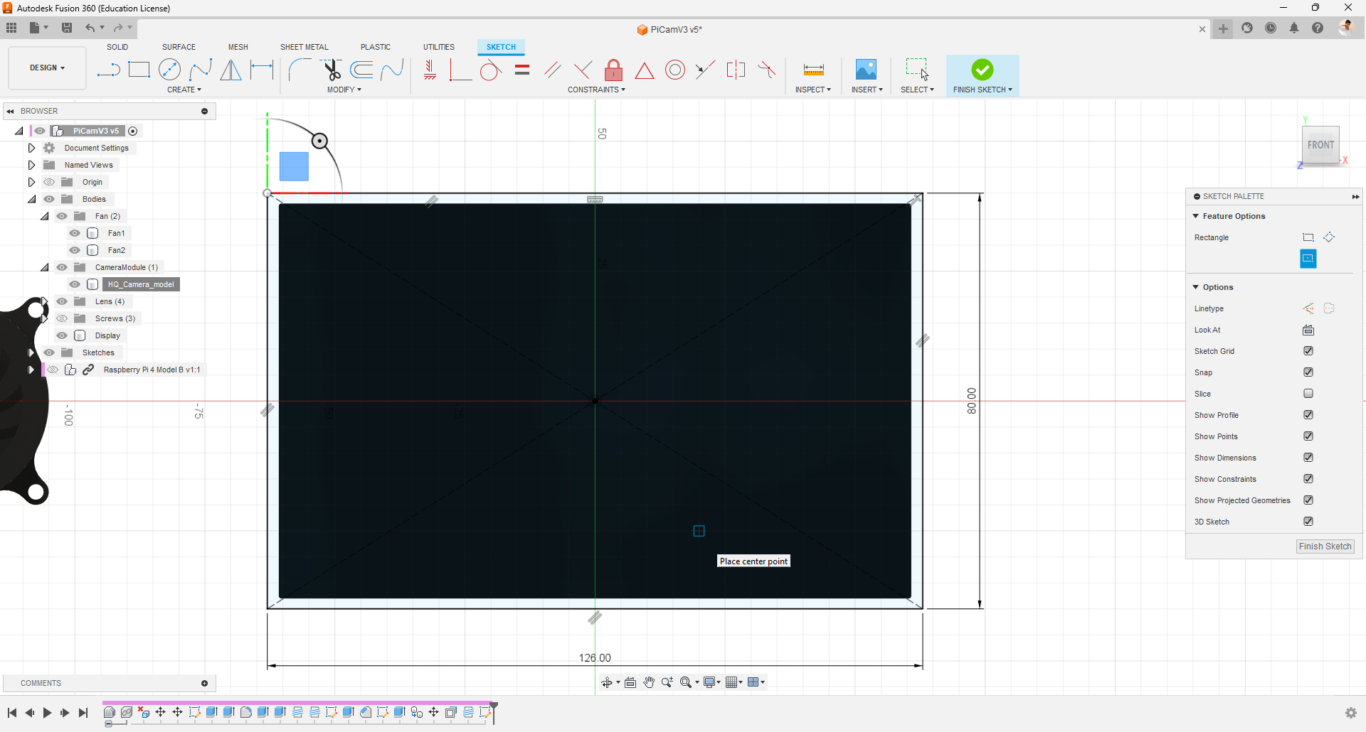
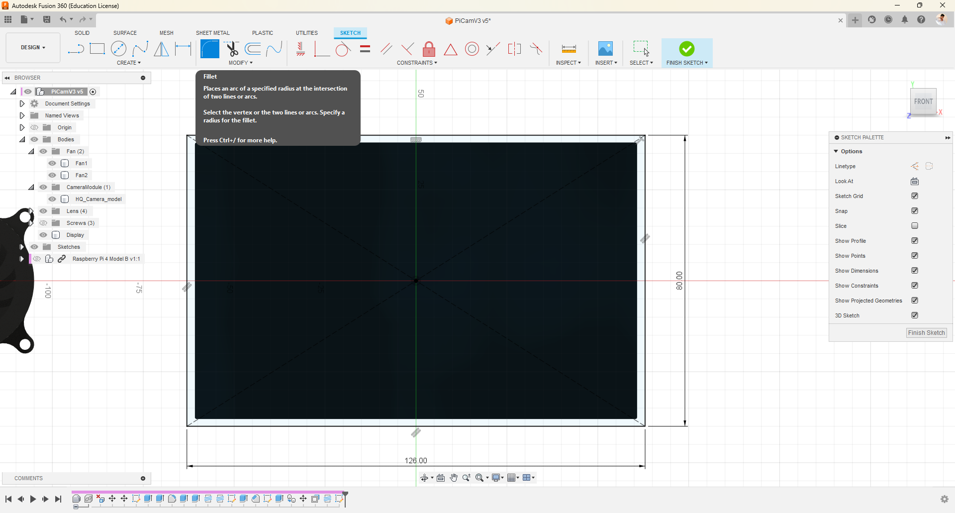
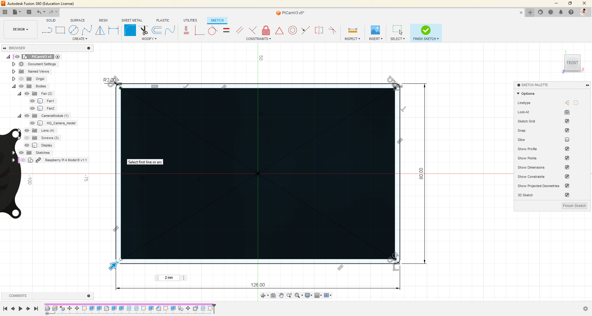
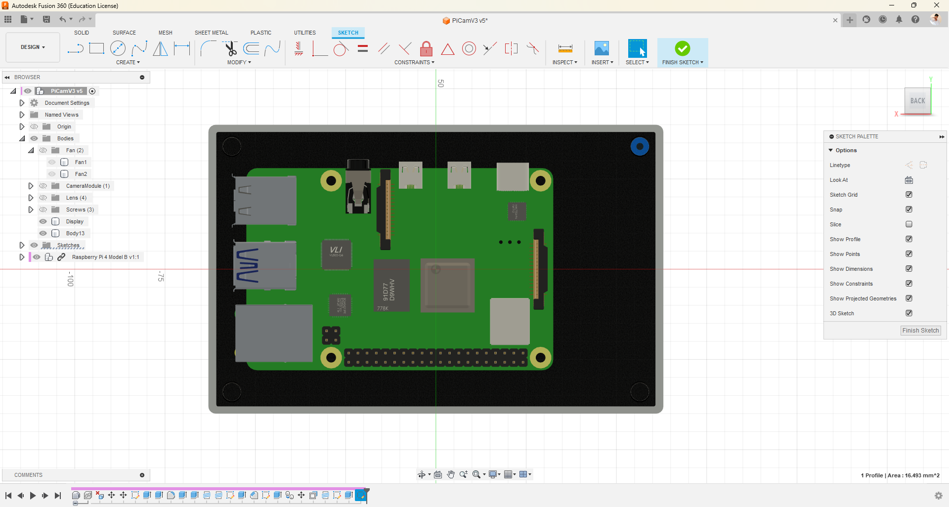
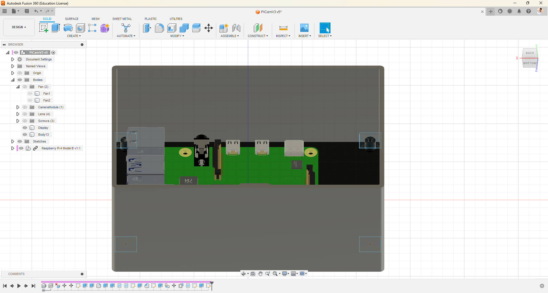
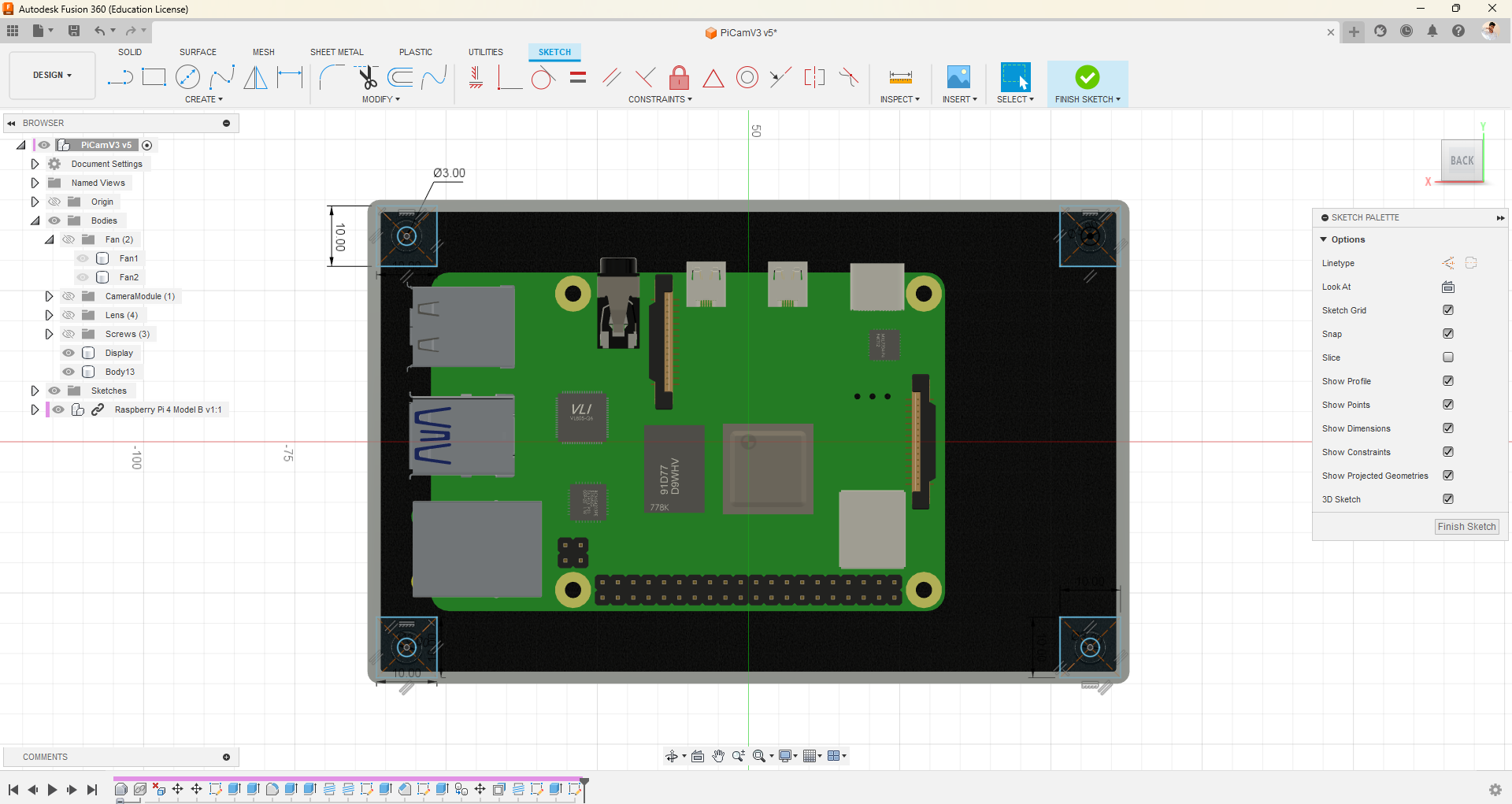
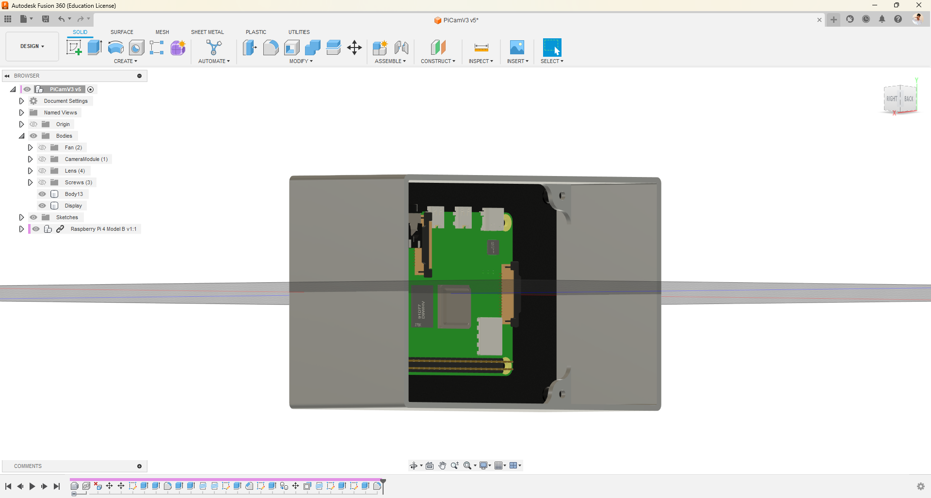
- First, draw a center rectangle on the display's front surface, with dimensions identical to the display but with an additional 2mm offset on all sides.
- You can directly use fillet in our 2D drawing.
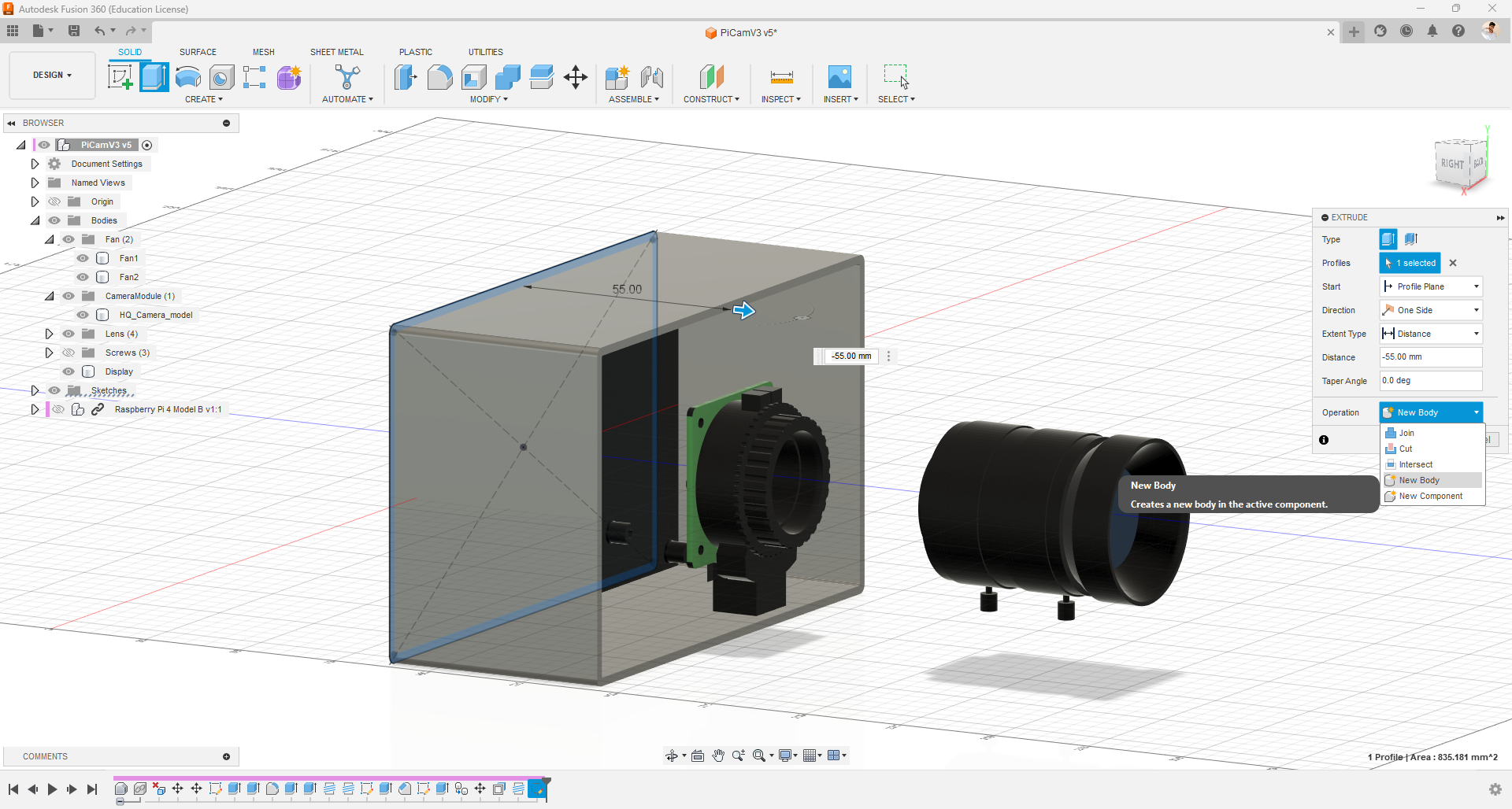
- Next, pull the drawing by 55mm.
- To mount the display on the case, I used the draw and press-pull method with the fillet option to design structures on all four corners, allowing me to mount the display using M2.5 screws.
Embedding Port Slots
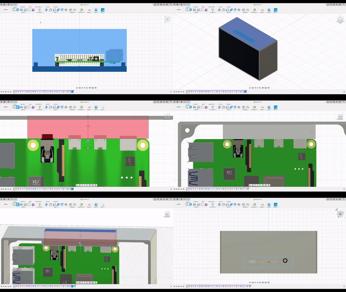
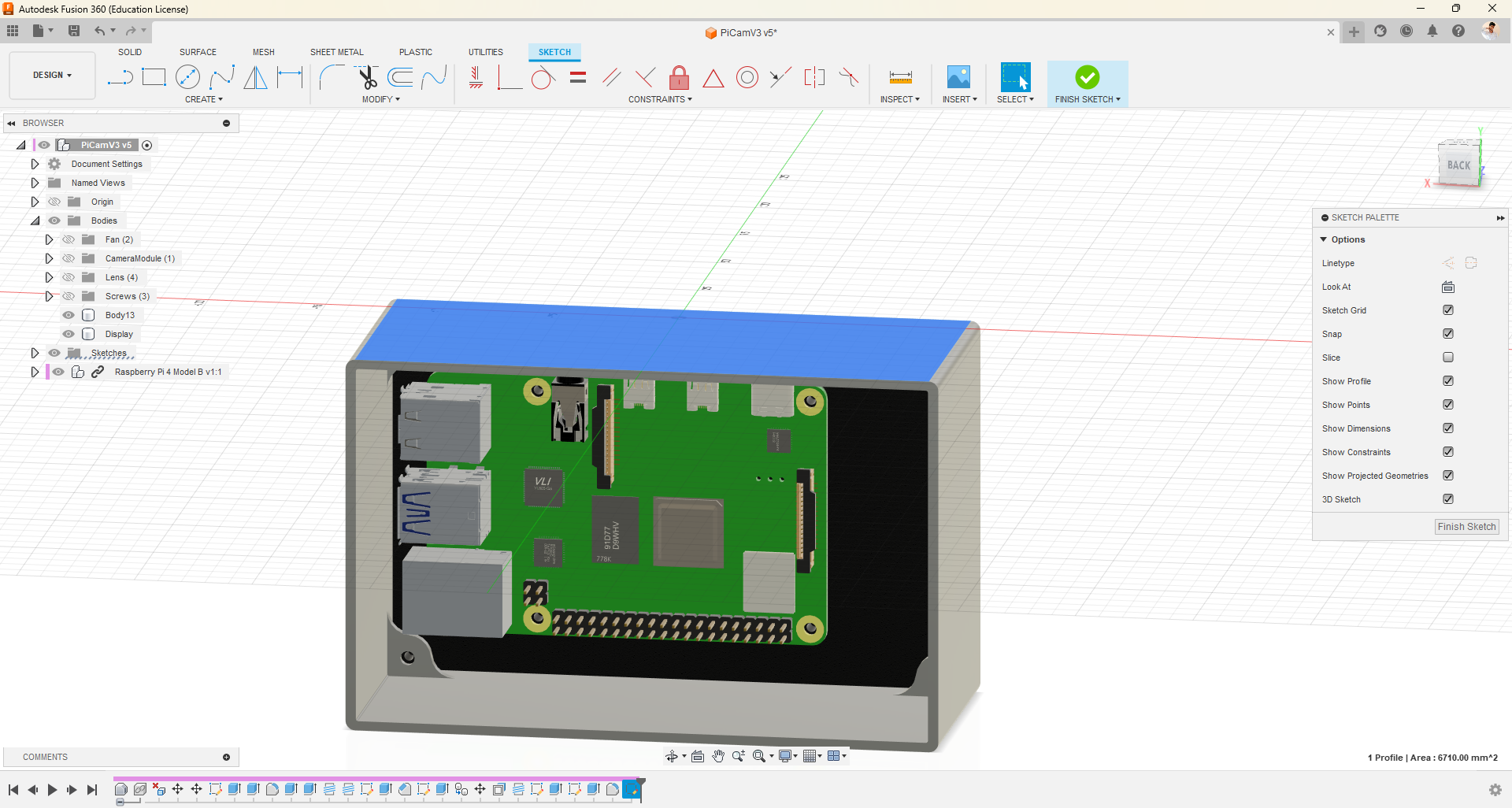
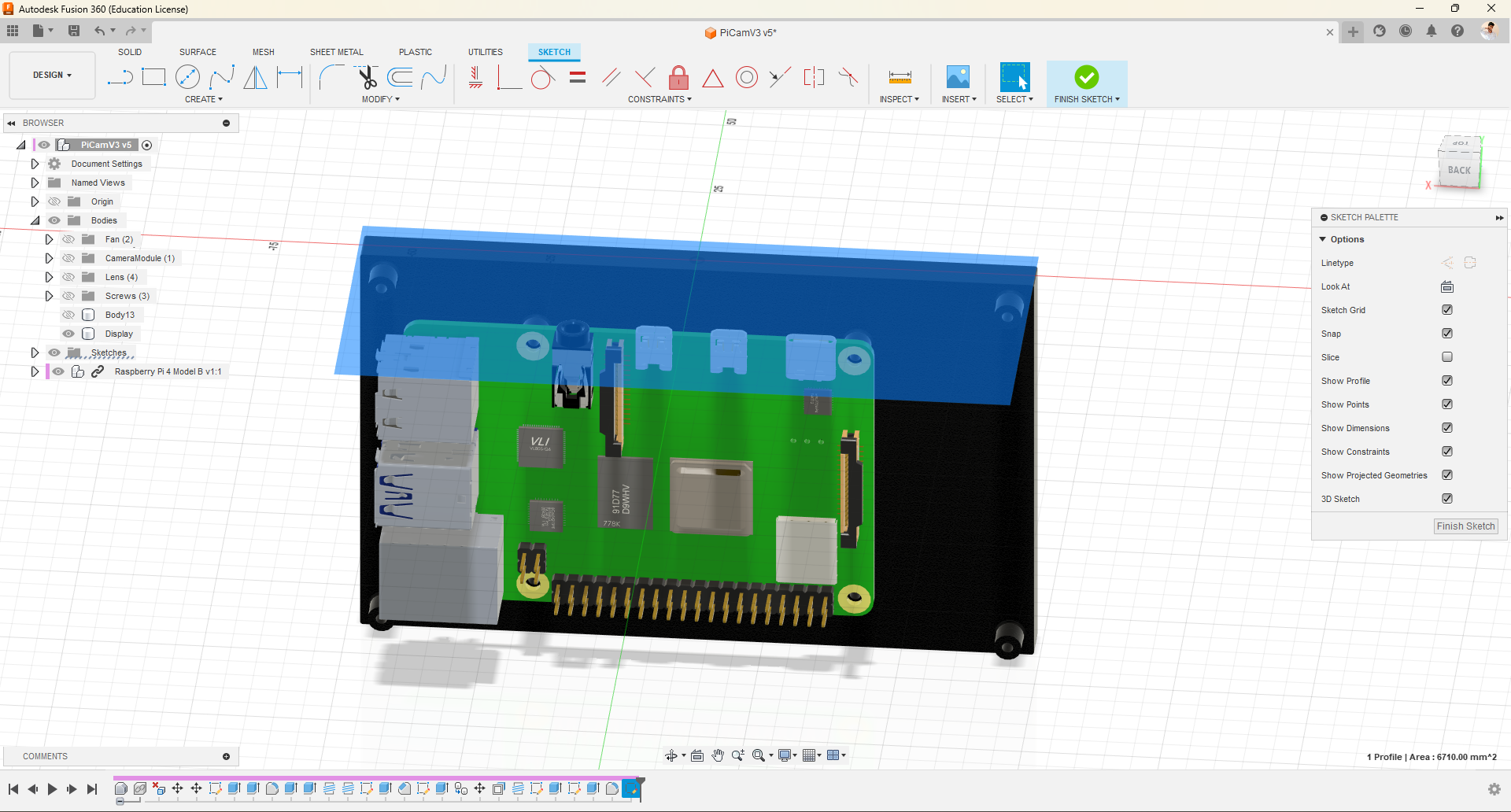
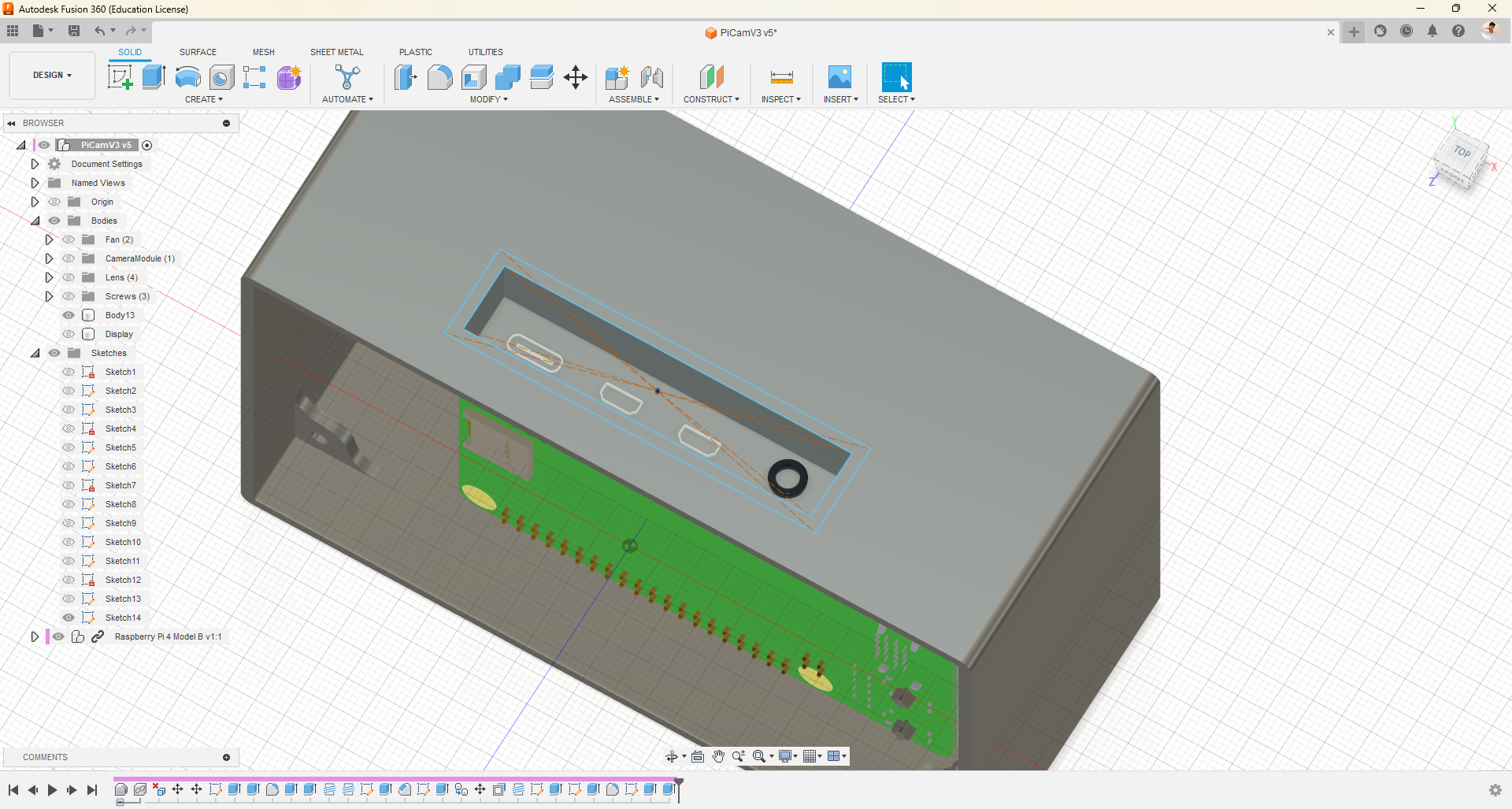
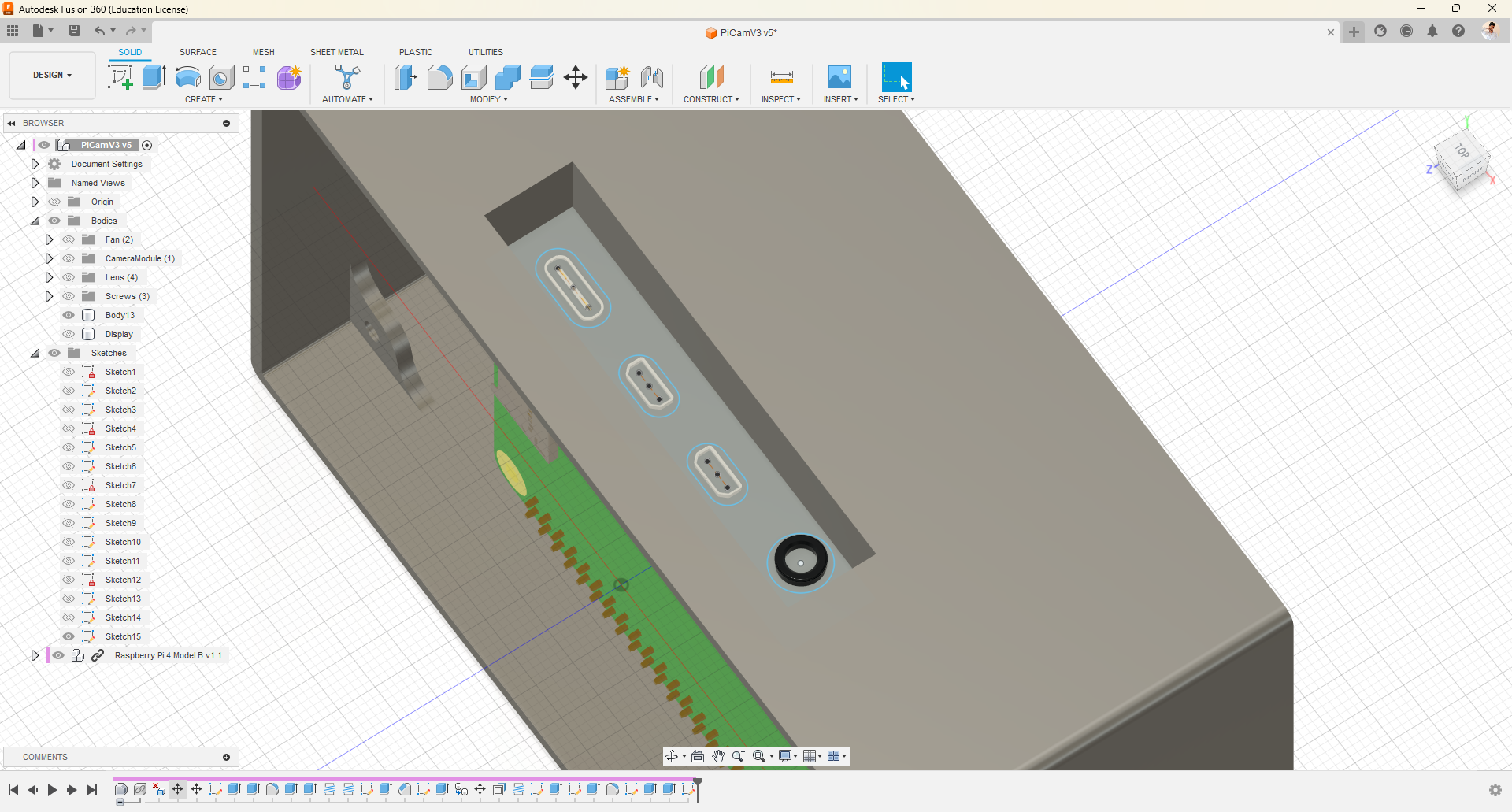
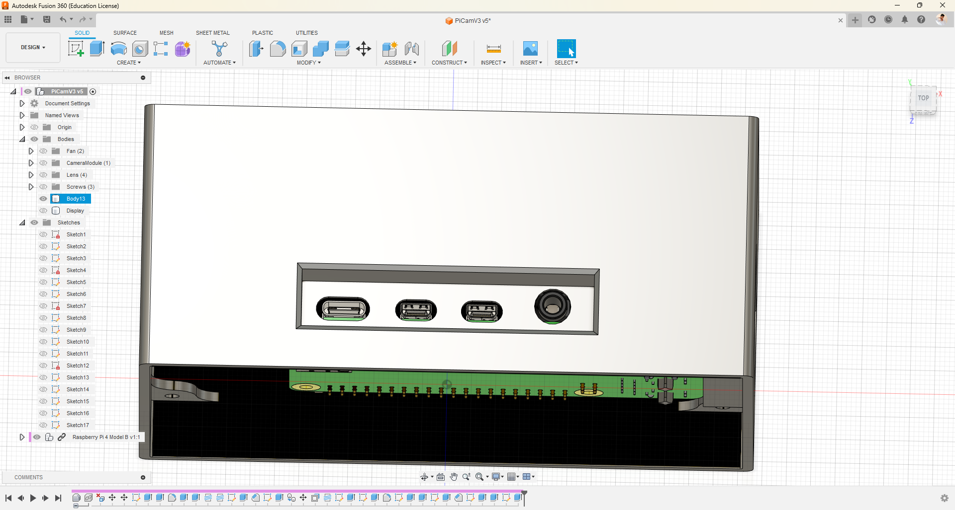
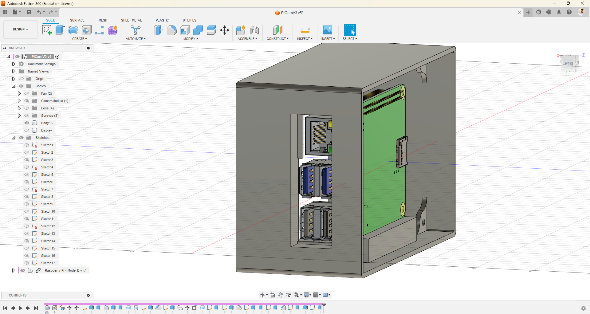
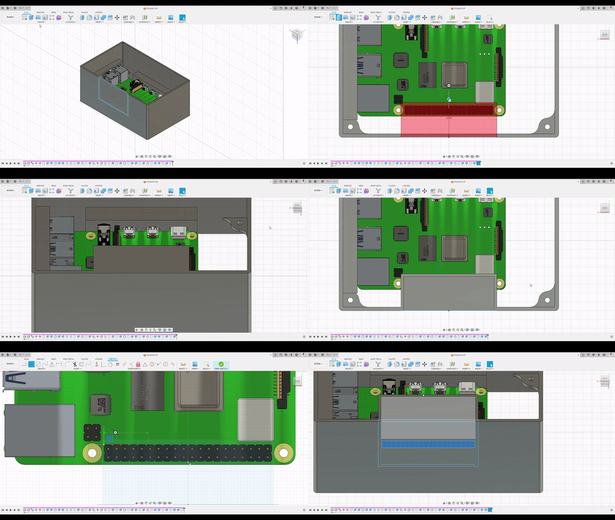
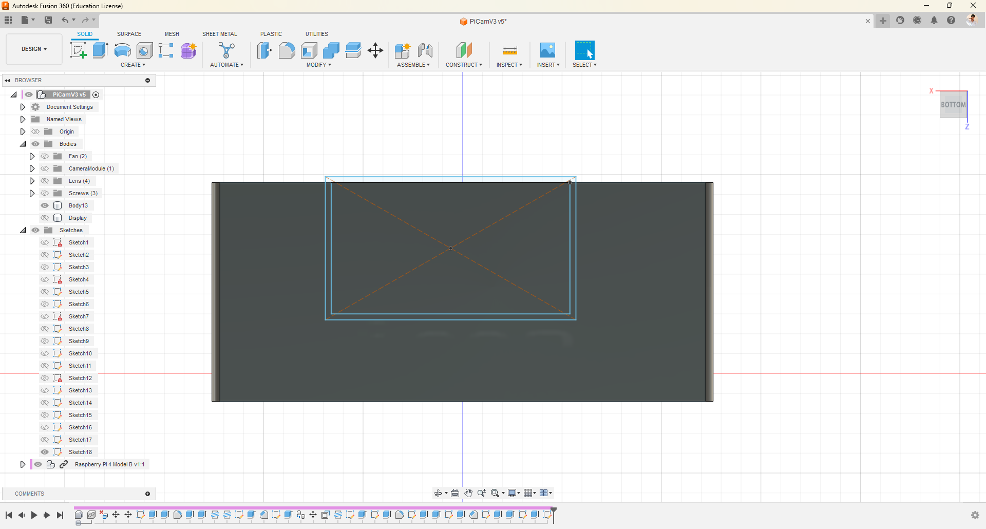
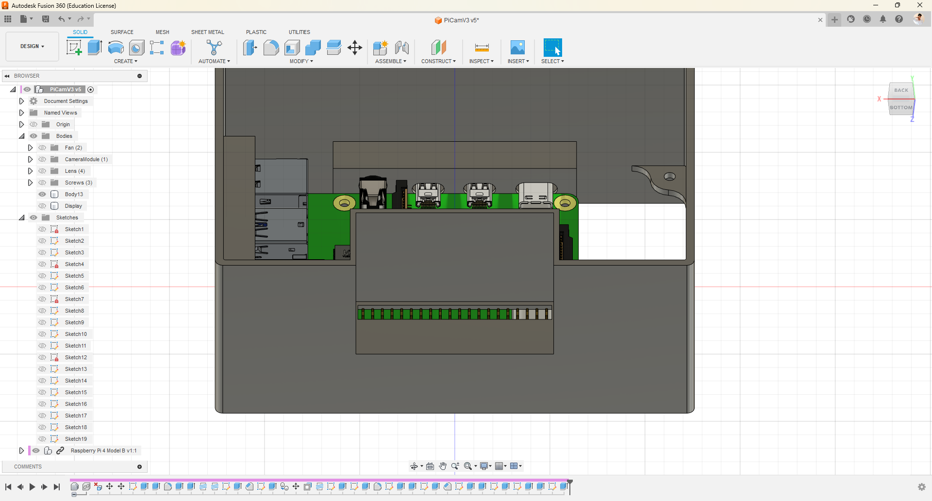
- Now, we need to provision access to the ports and pins.
- To accomplish this, utilize the drawing, pressing, and pulling features.
- Observe how I achieved it.
- Note that I am using the Raspberry Pi as a reference for drawing, pressing, and pulling.
Splitting the Body
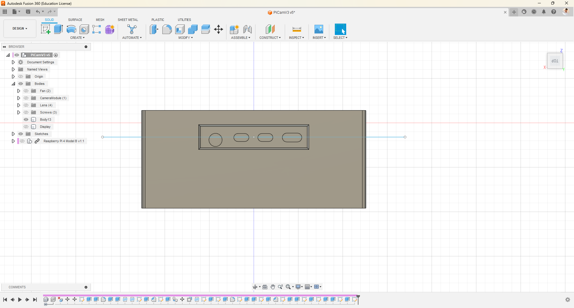
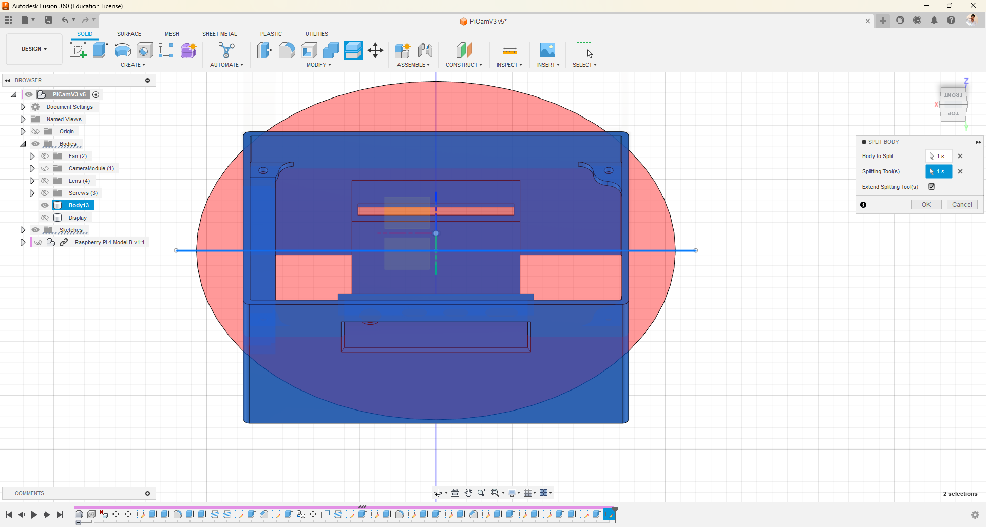
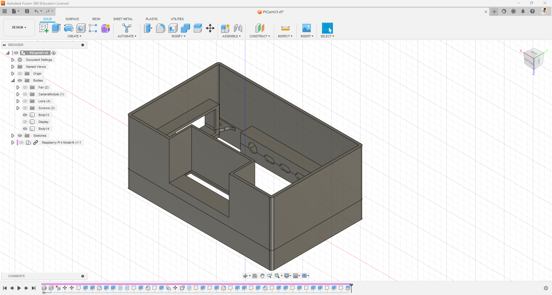
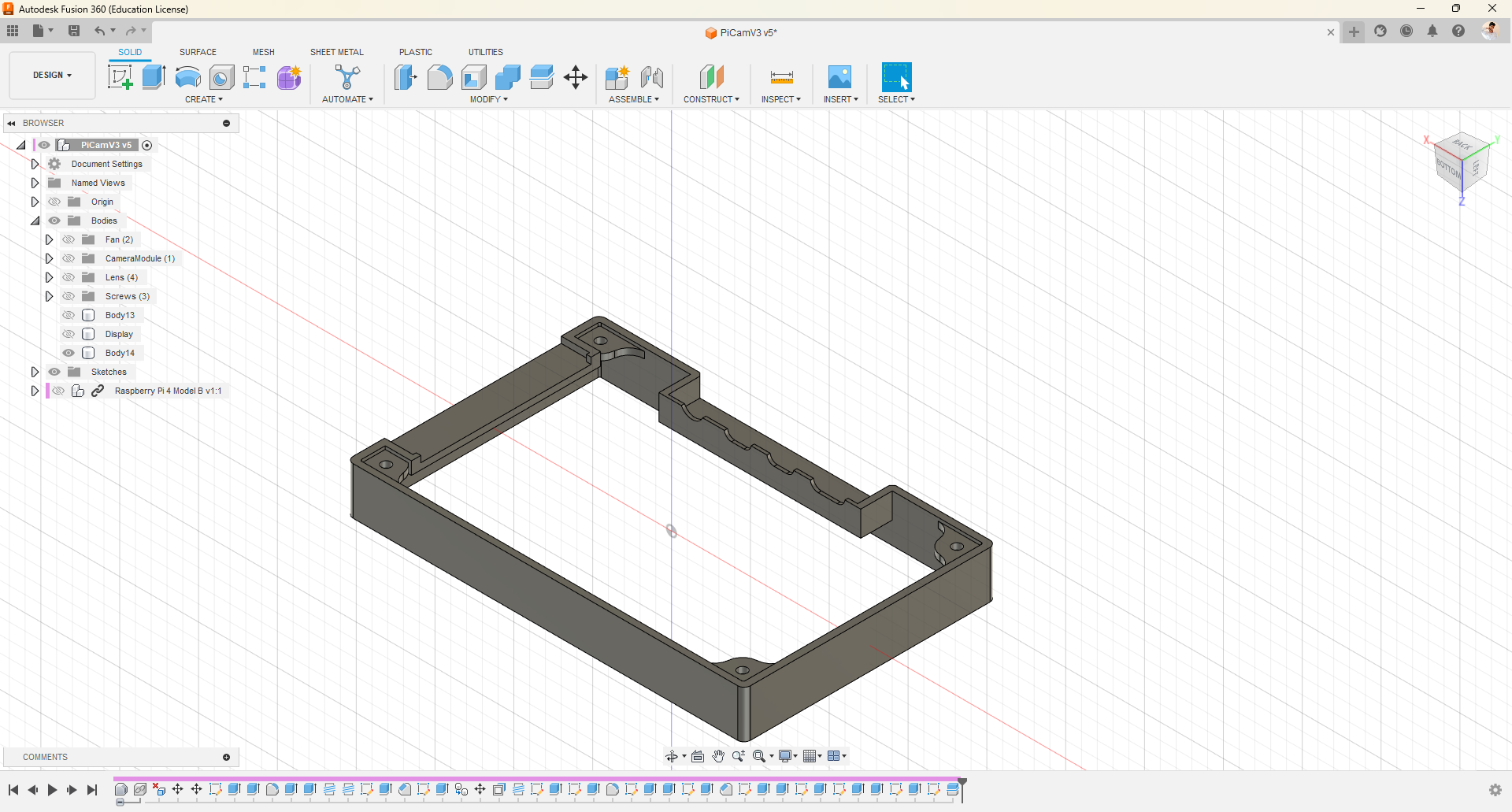
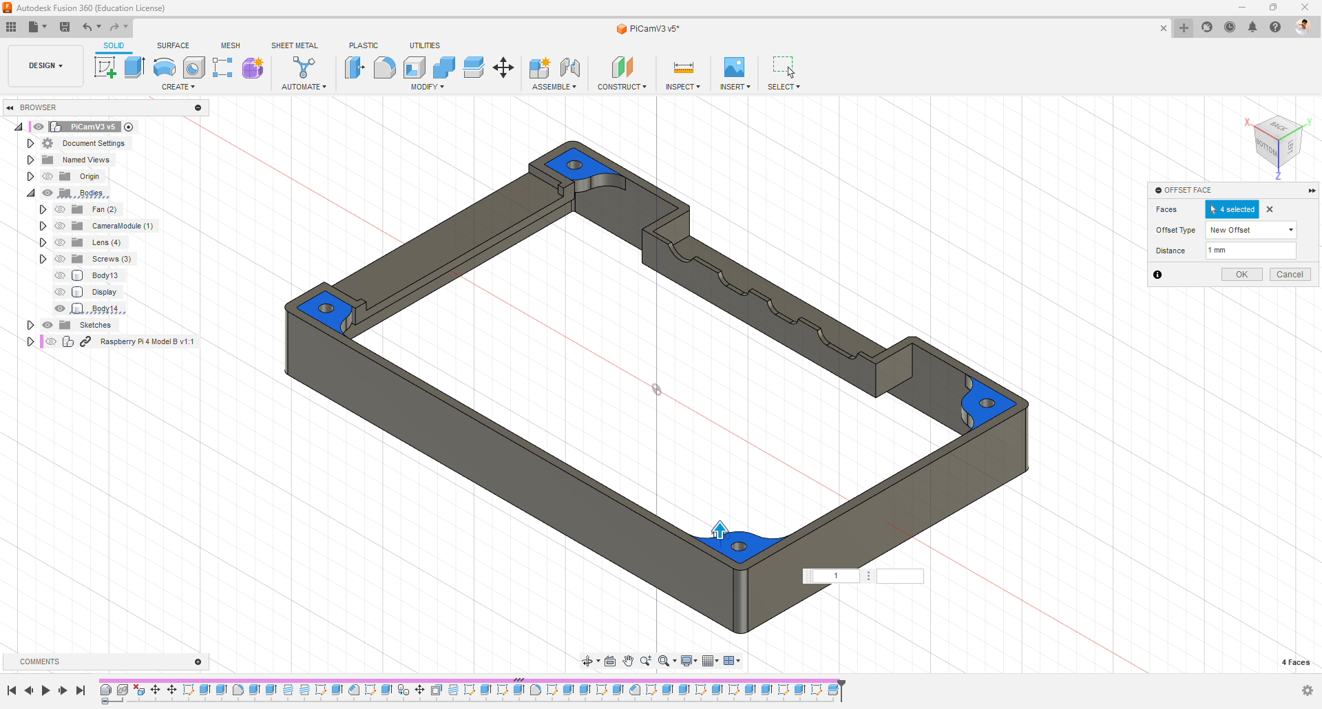
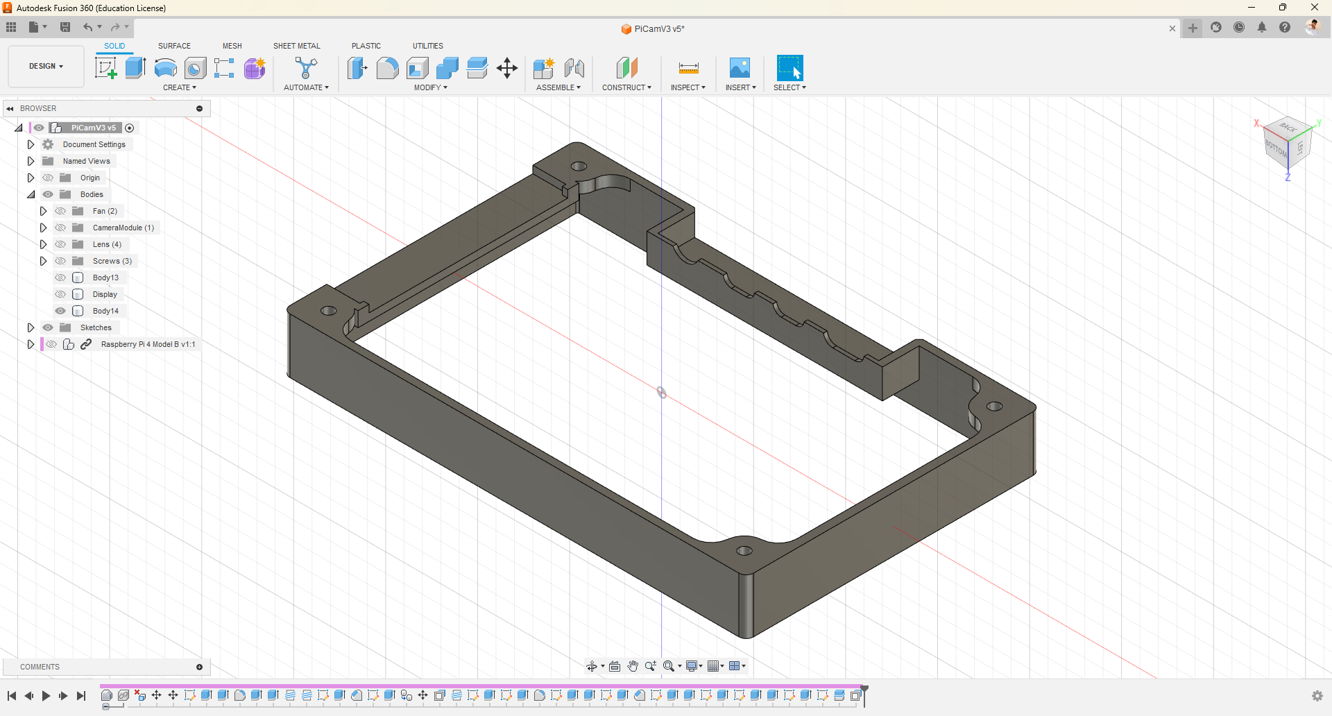
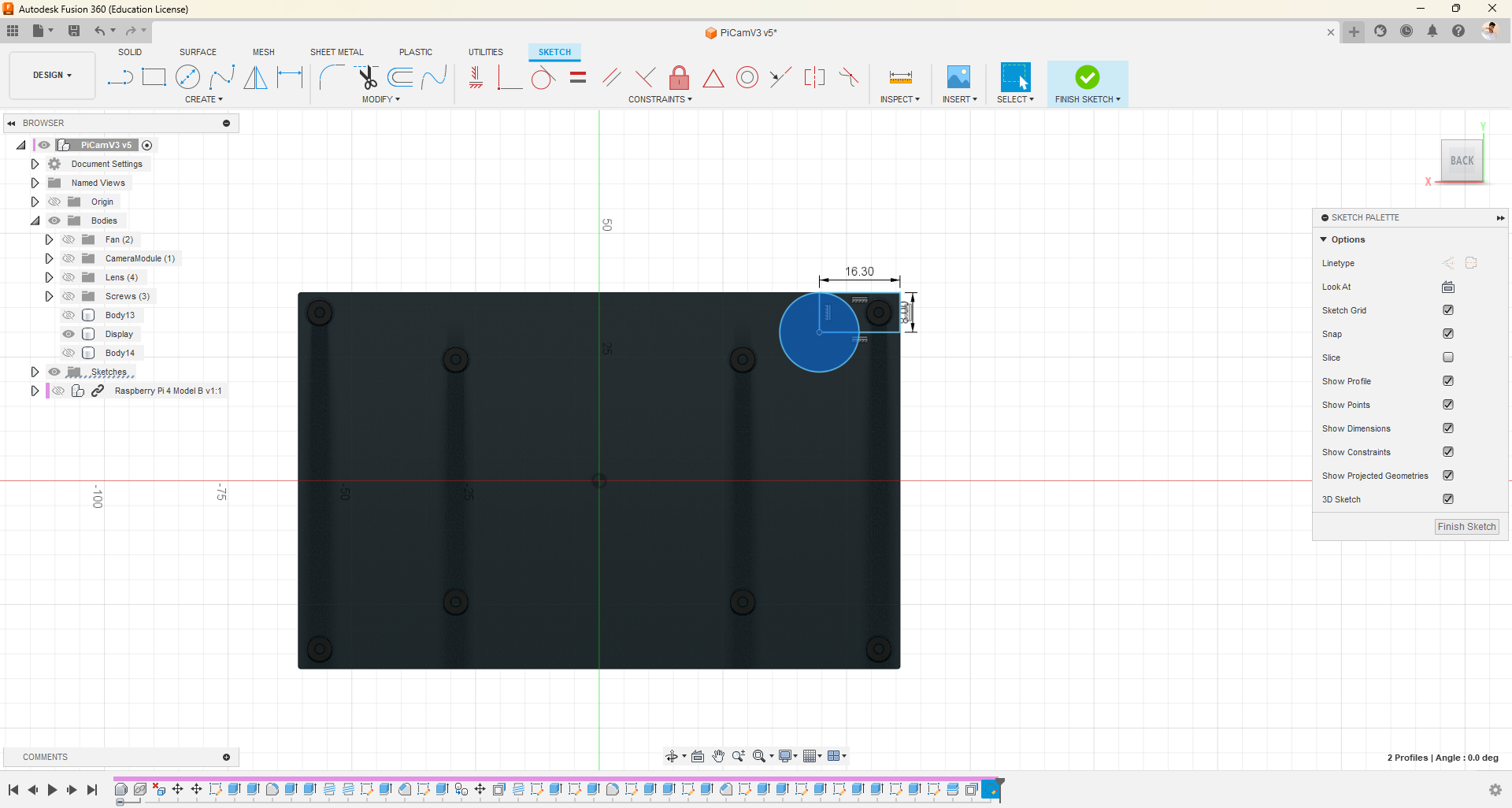
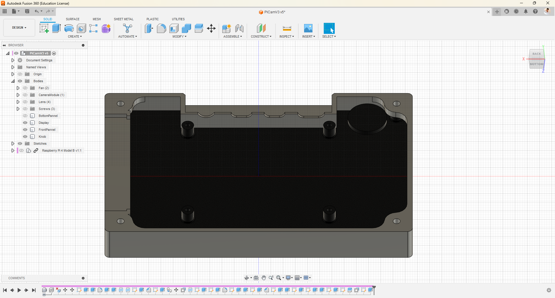
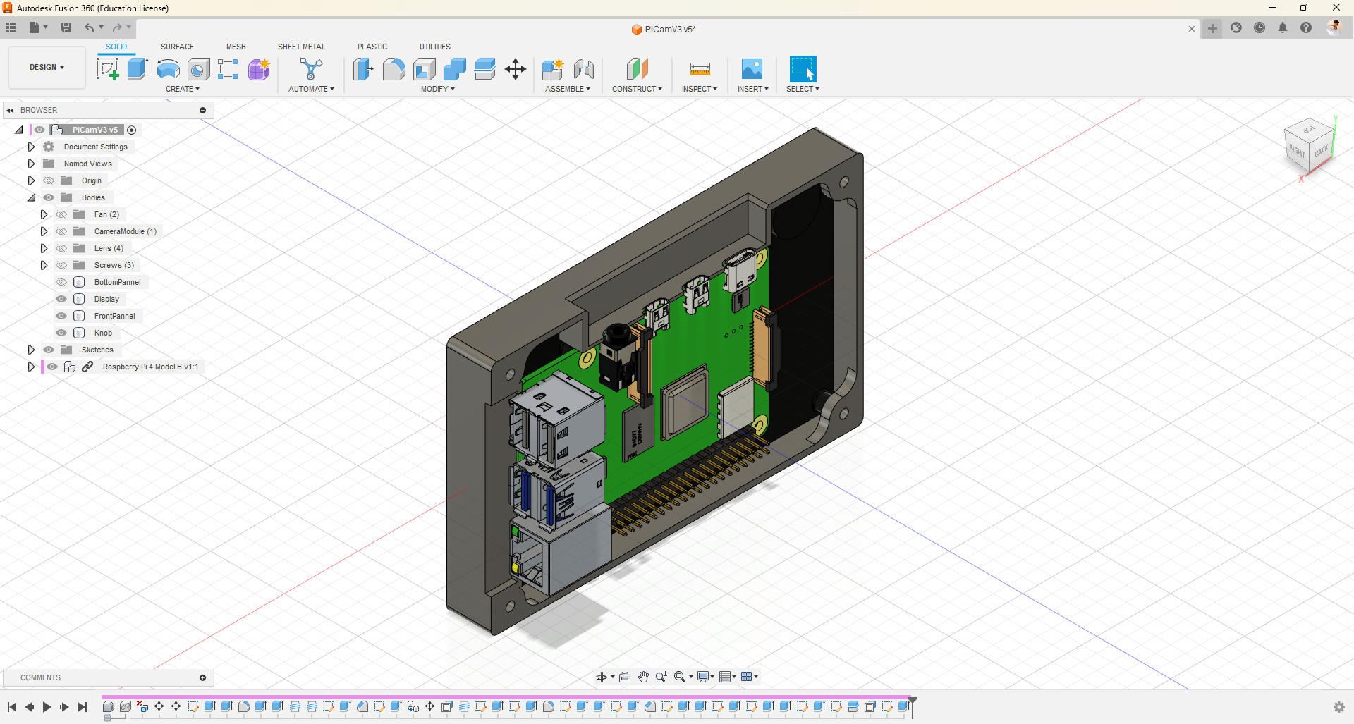
- In this step, we are going to use the Split feature to separate a single body into two halves.
- Draw a line on the surface where you want to make the cut.
- Next, select the Split Body option and choose the body you want to split, as well as the line we drew as the splitting tool.
- After the split, I made a few modifications for a better structure.
- Additionally, attach this knob so that we can ensure the new design components do not conflict with this element.
Providing Component Slots
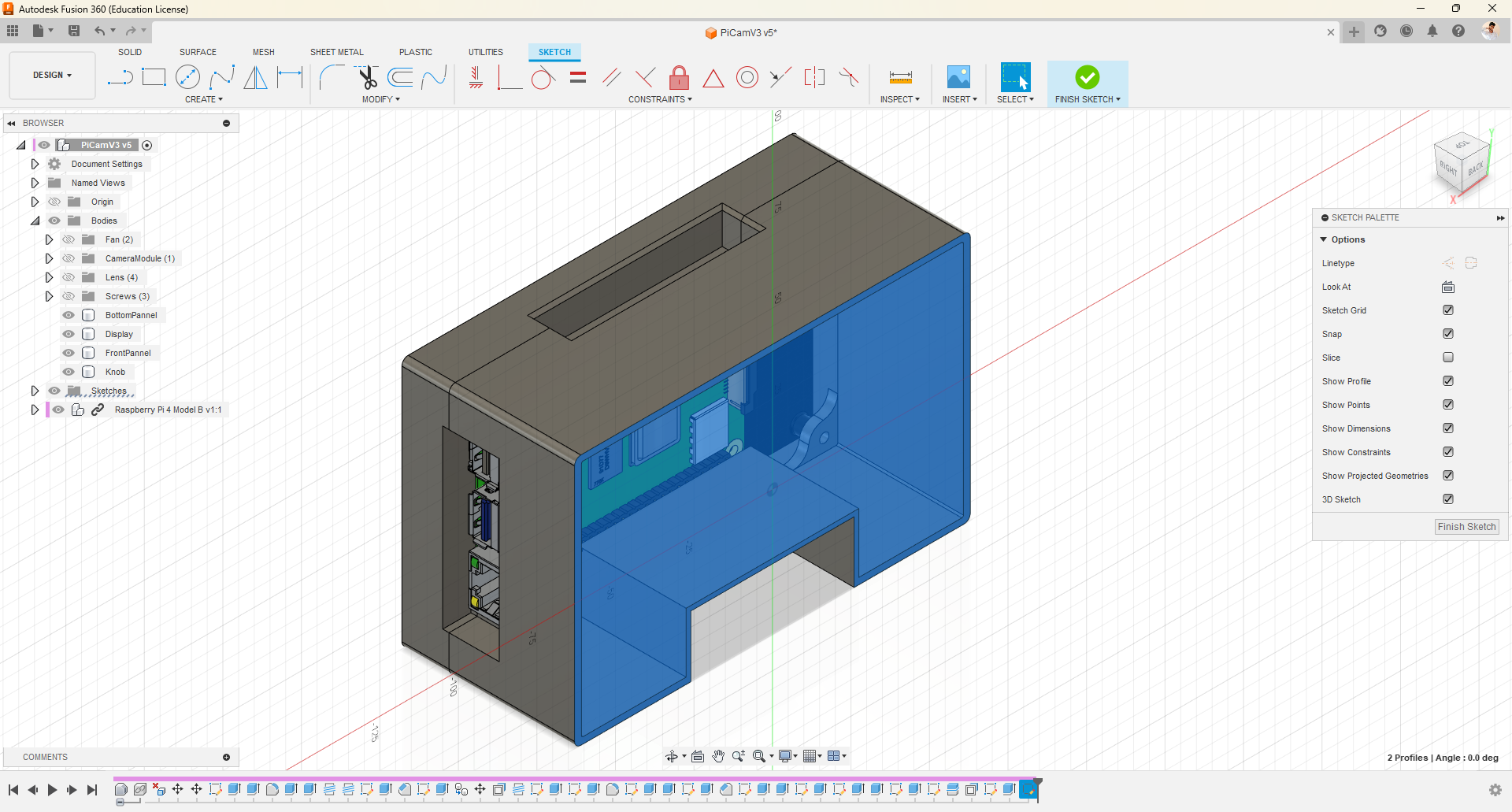
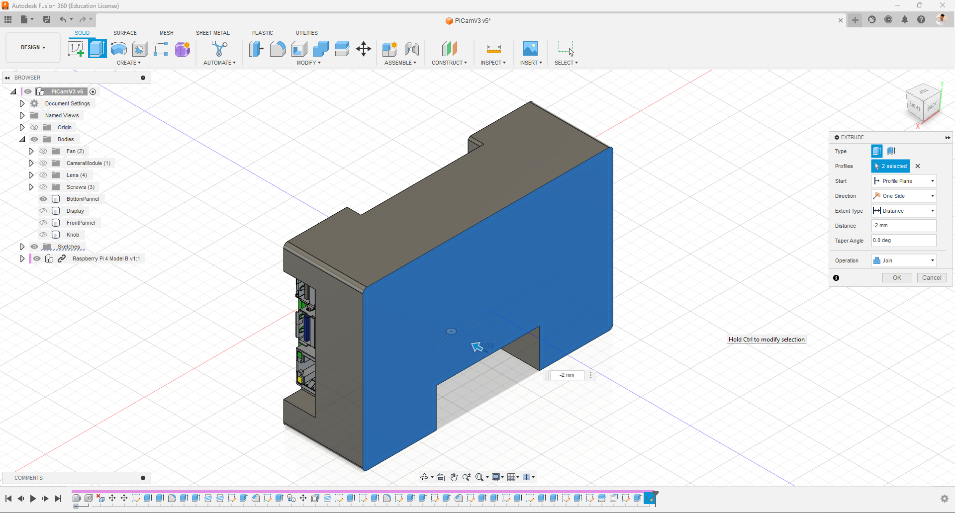
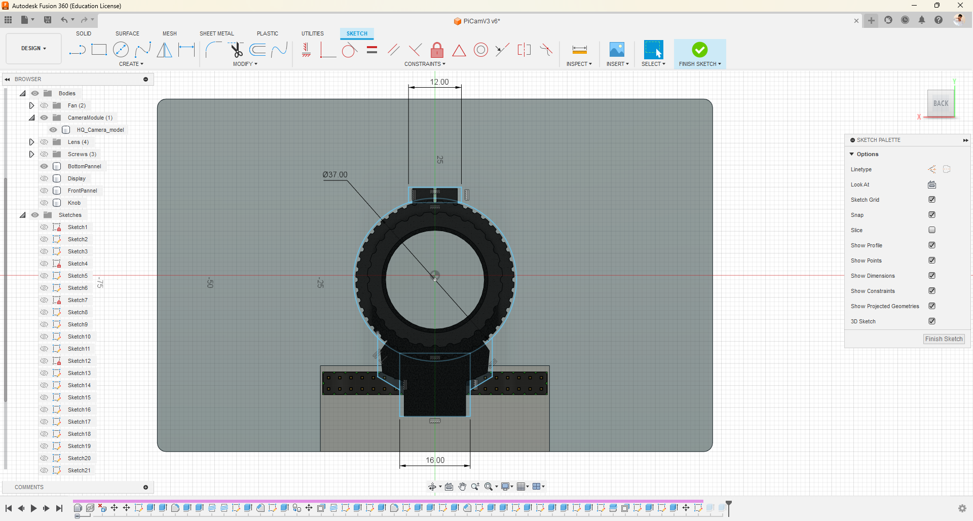
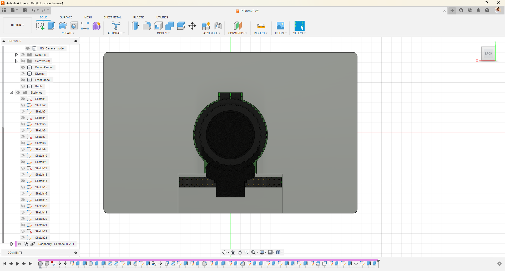
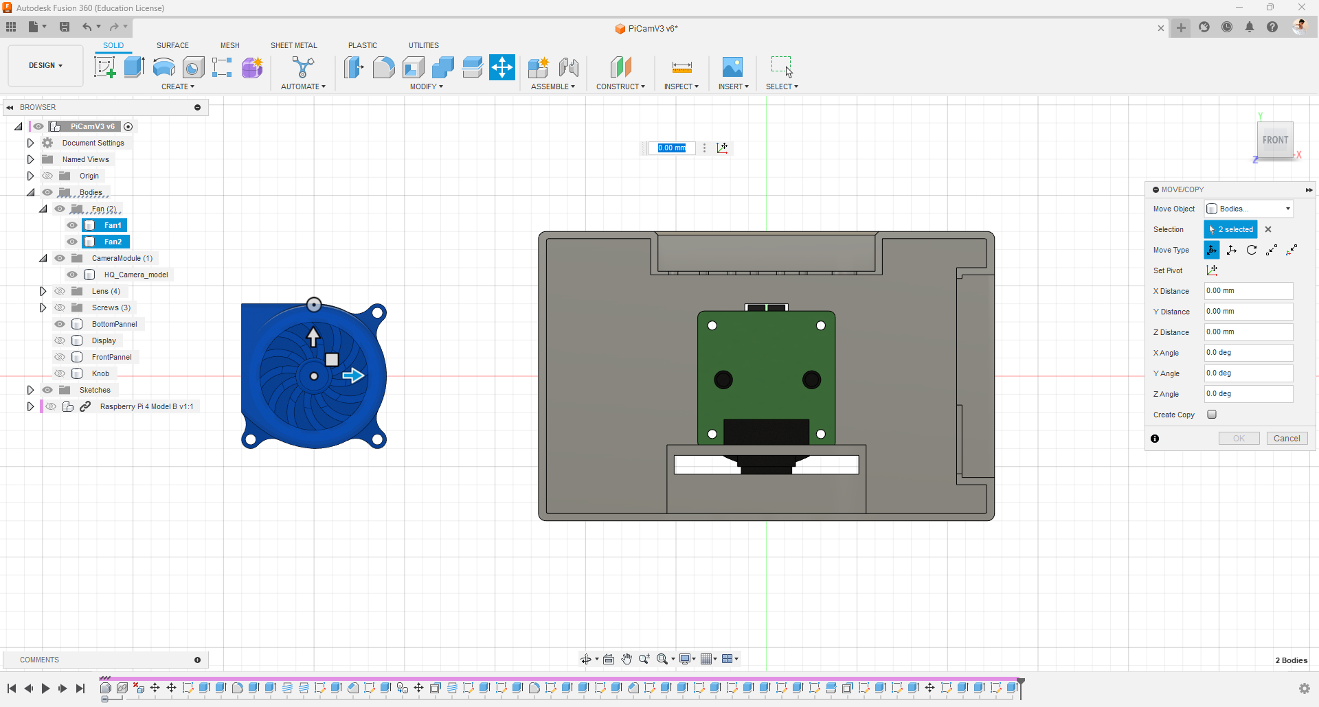
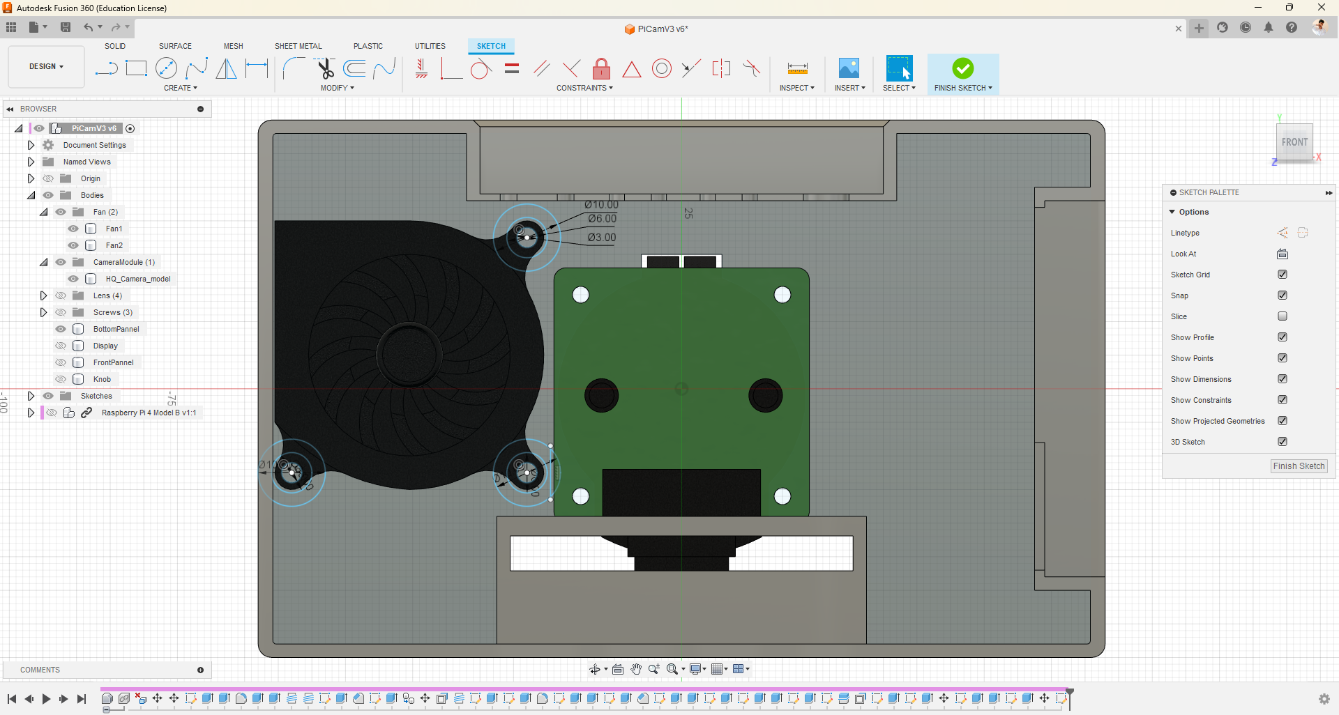
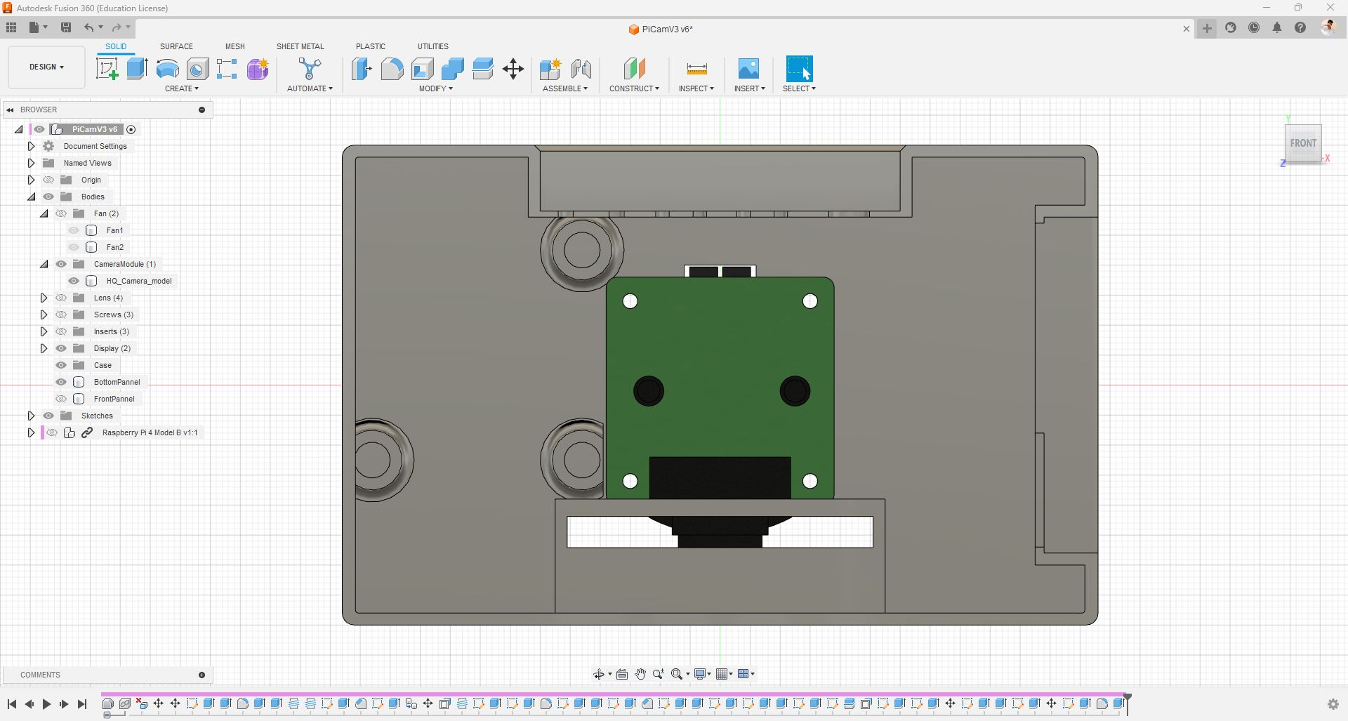
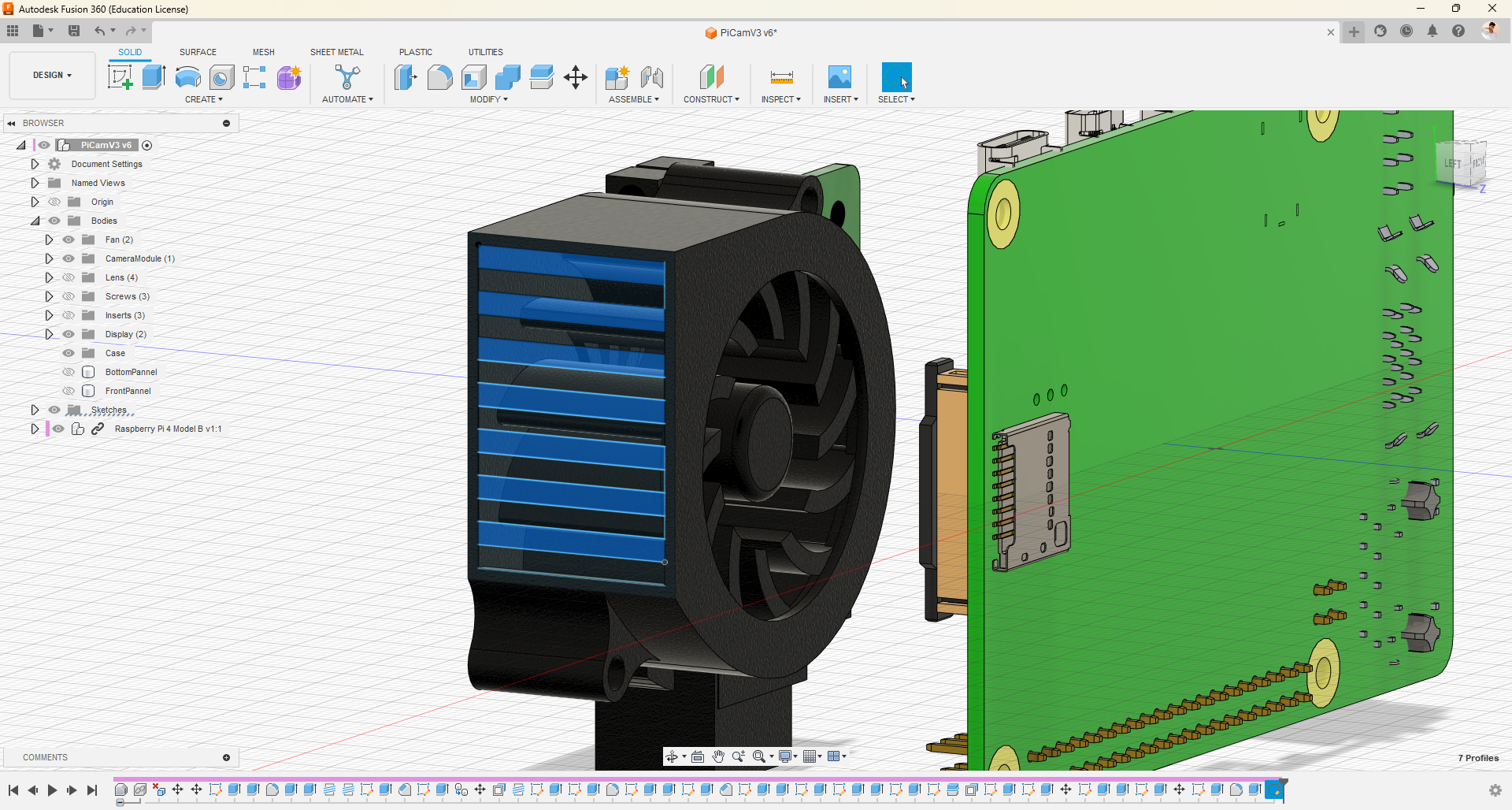
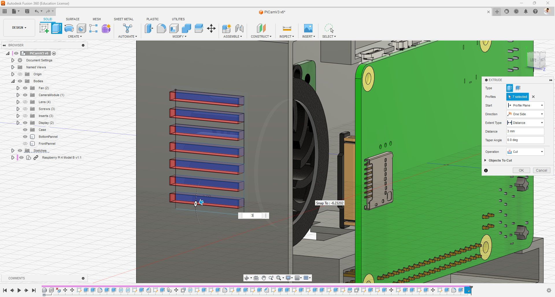
- Now, I closed the open surface of the base panel with a 2mm wall.
- Then, I drew the approximate size on the same surface for the Raspberry Pi HQ Cam module and pressed it in such a way that the HQ module can be mounted to the base panel.
- Also design the structure for putting metal inserts to put the fan with M2 20mm screws, use fan as reference.
- On the other side, towards the fan exhaust, I cut an opening to allow air to escape from the enclosure, using the fan as a reference.
Model Analysis
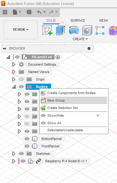
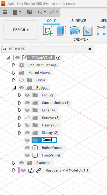
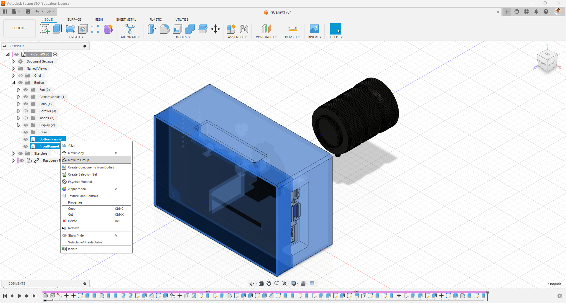
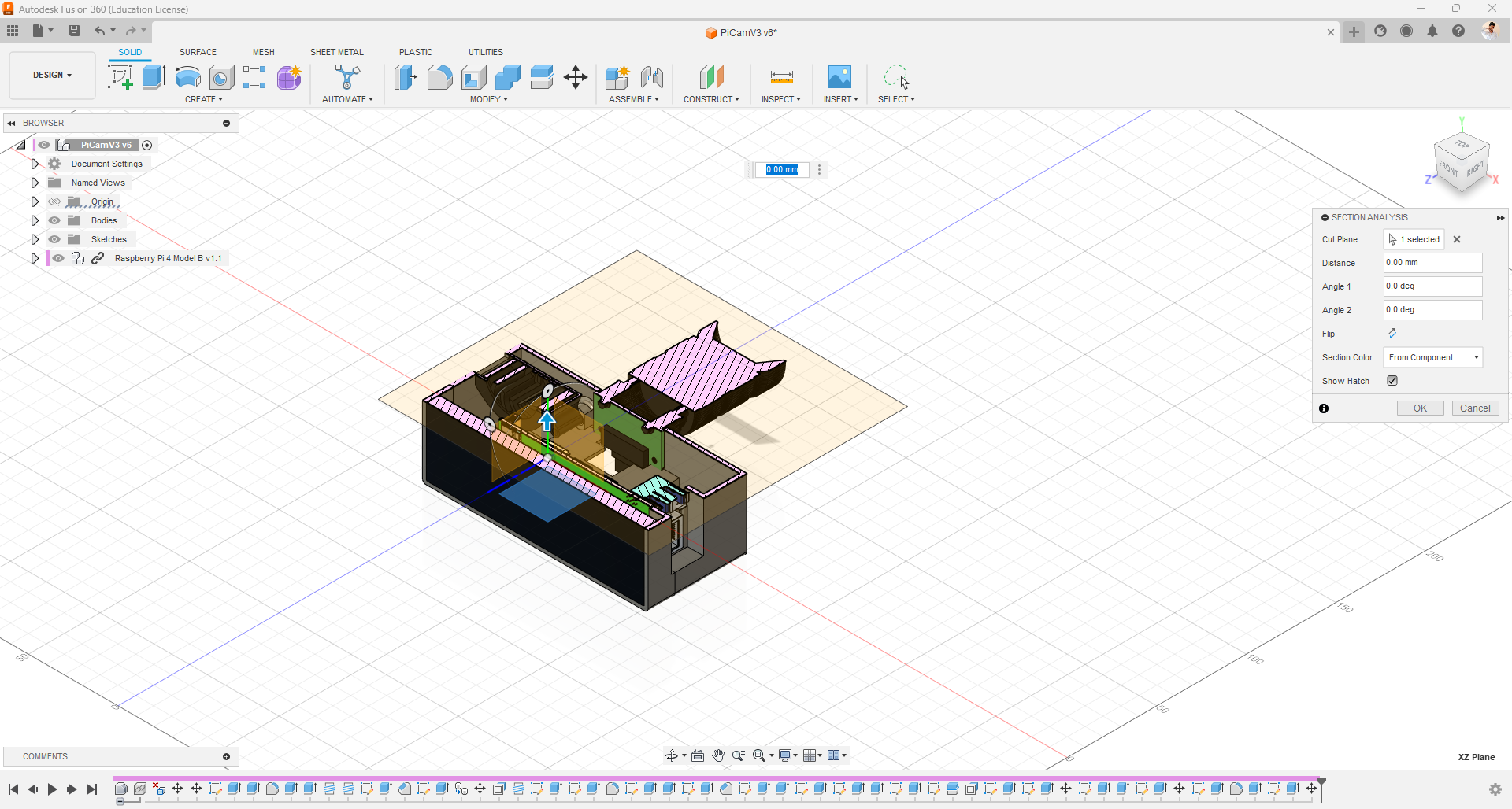
- In this step, we are going to organize various bodies and components by grouping them in a folder. This allows us to easily view or hide all the grouped components with just one click.
- To do that, follow these steps: right-click on the project directory, select the bodies you want to group, right-click again, choose "Move to Group," and select the desired group.
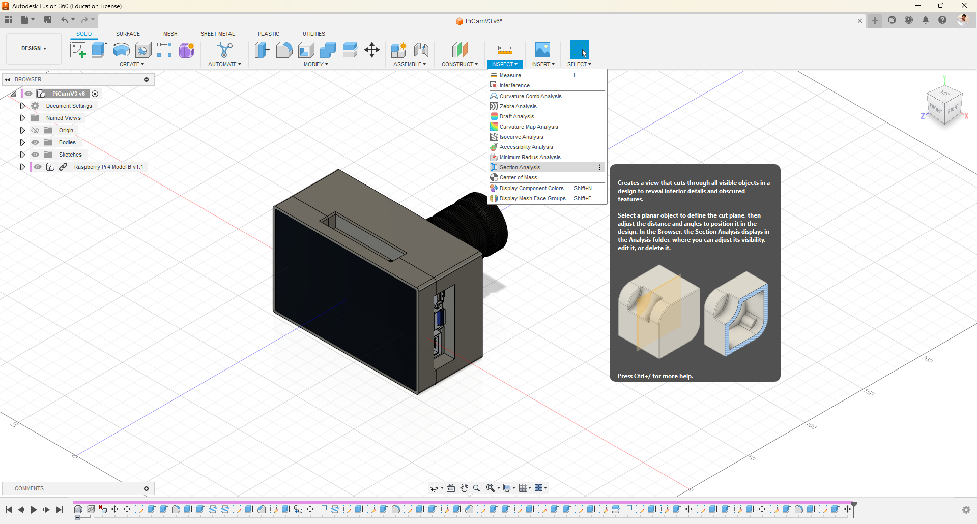
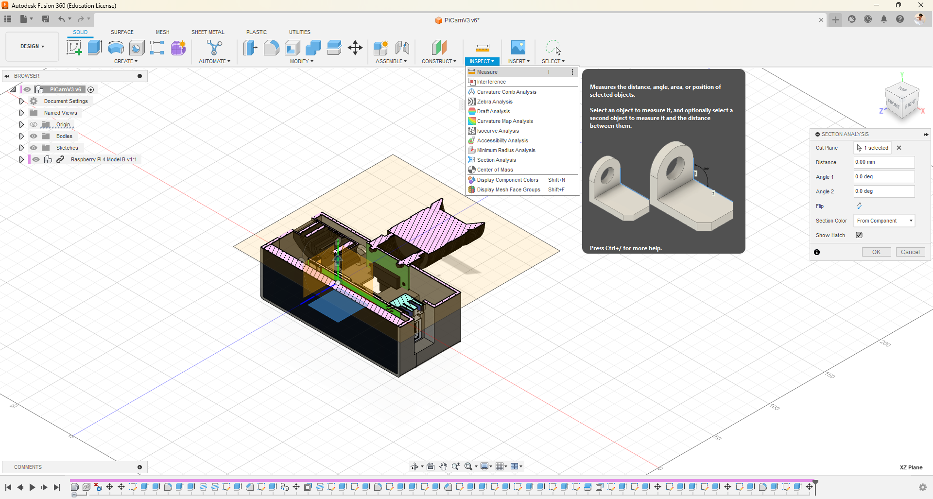
- In Fusion 360, we have a feature called section analysis, which enables us to view hidden parts of our design and inspect it thoroughly.
- Additionally, there is a measurement feature that allows us to measure different parameters such as length, radius, diameter, and angle.
Screw Fit
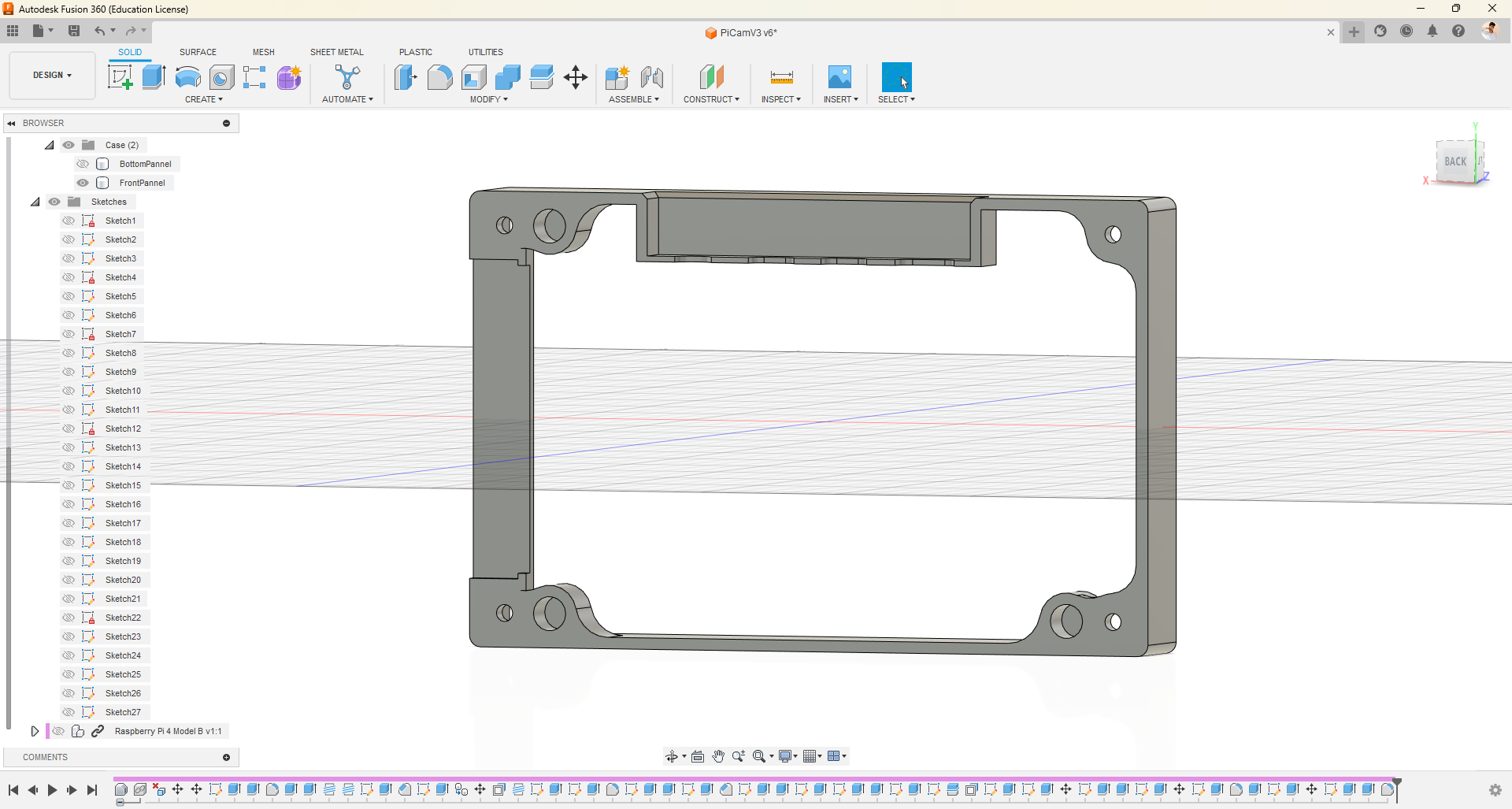
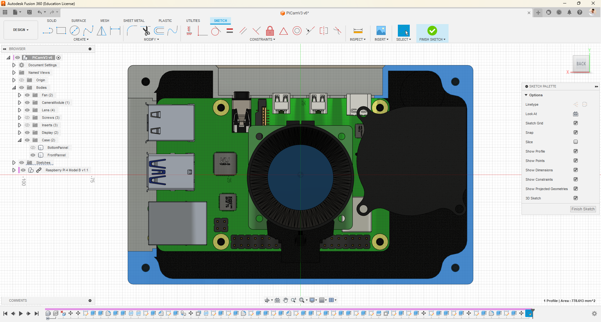
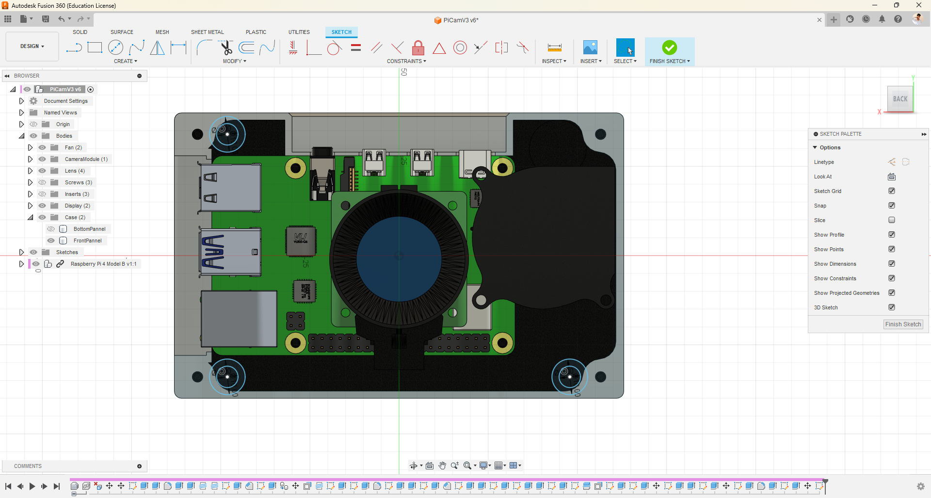
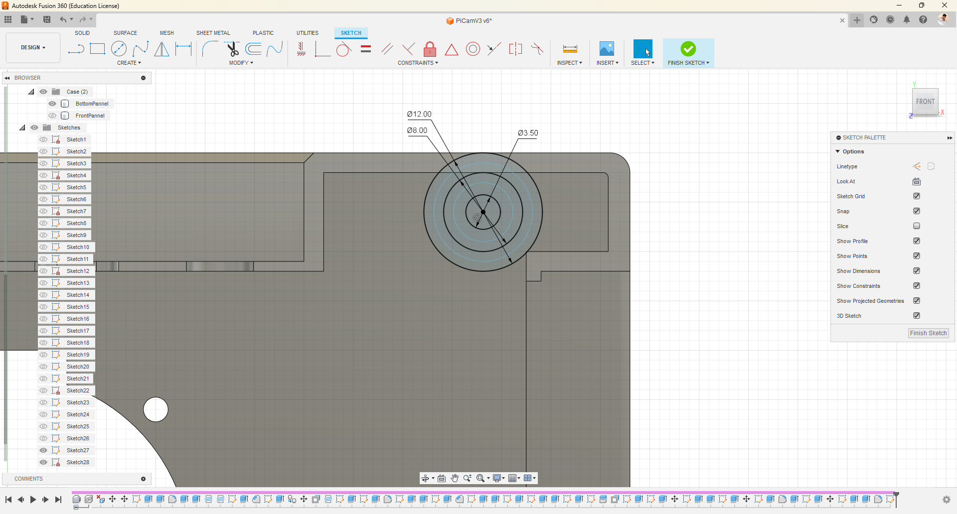
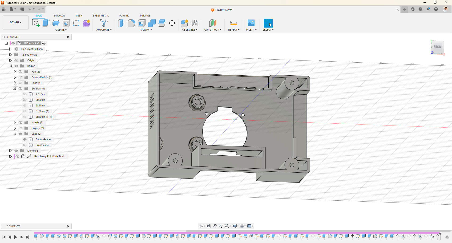
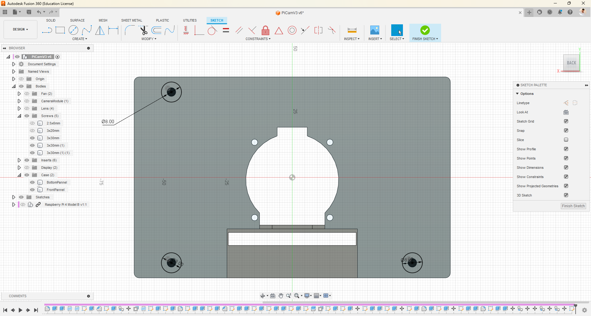
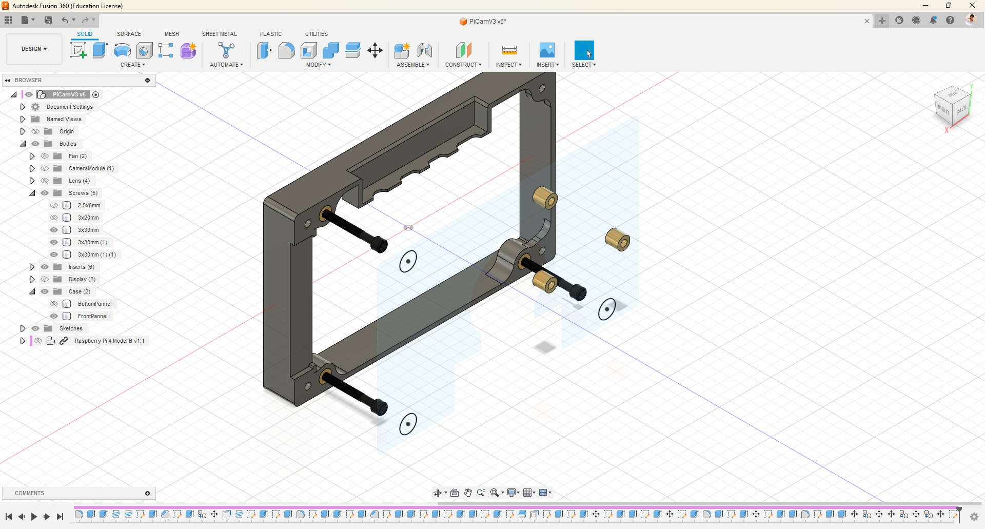
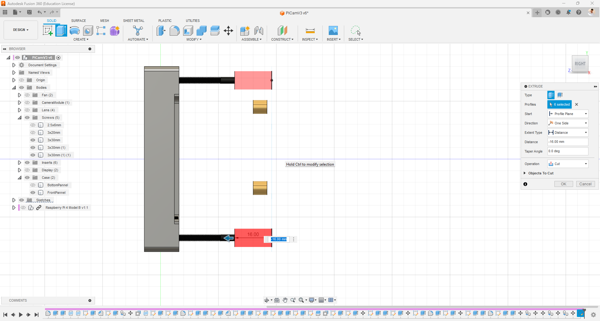
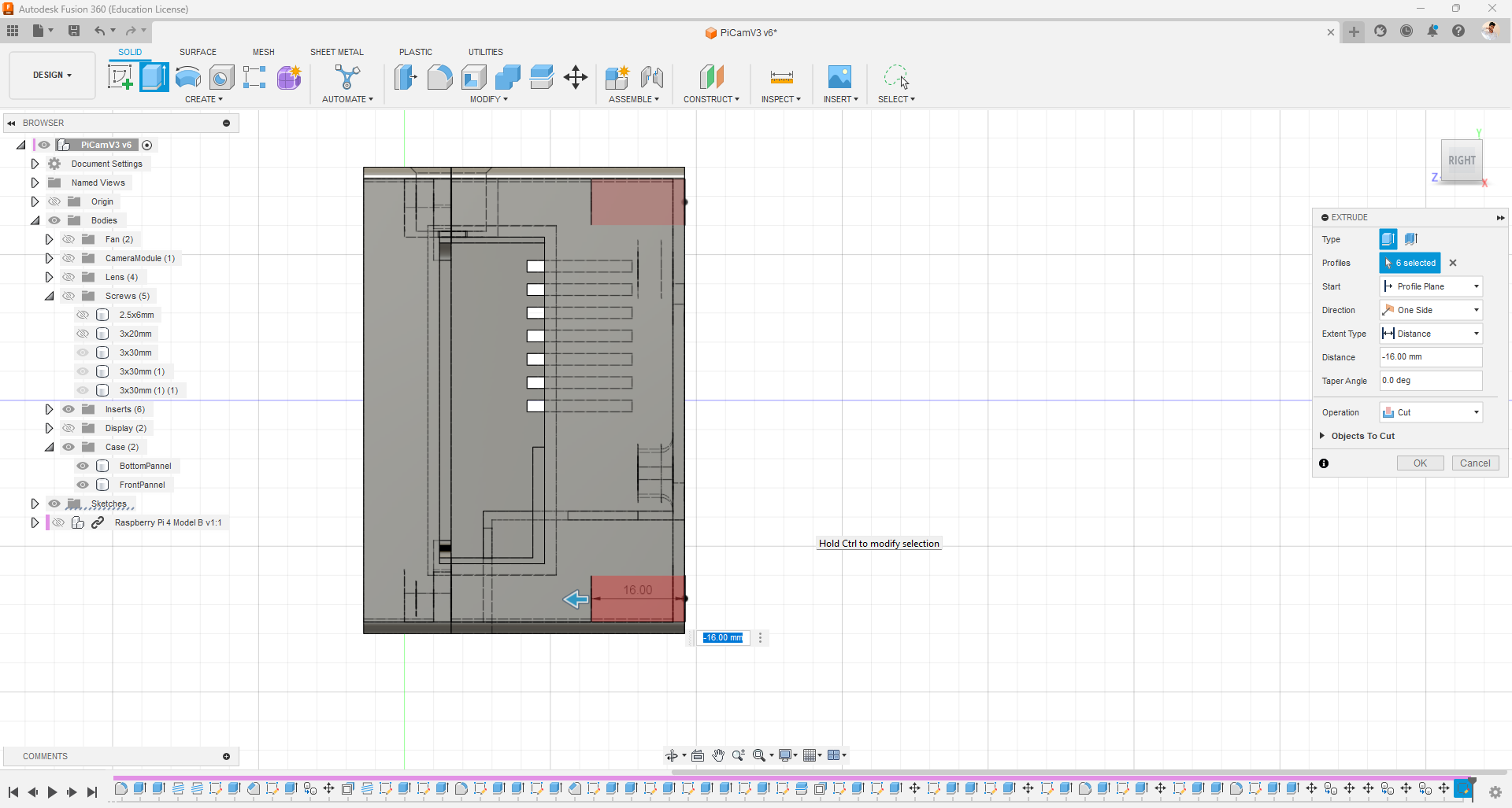
- Now it's time to put both enclosure pieces together. I have designed this screwing mechanism to join the components. Simply utilize the same basic features: draw, press, and pull.
Snap Fit
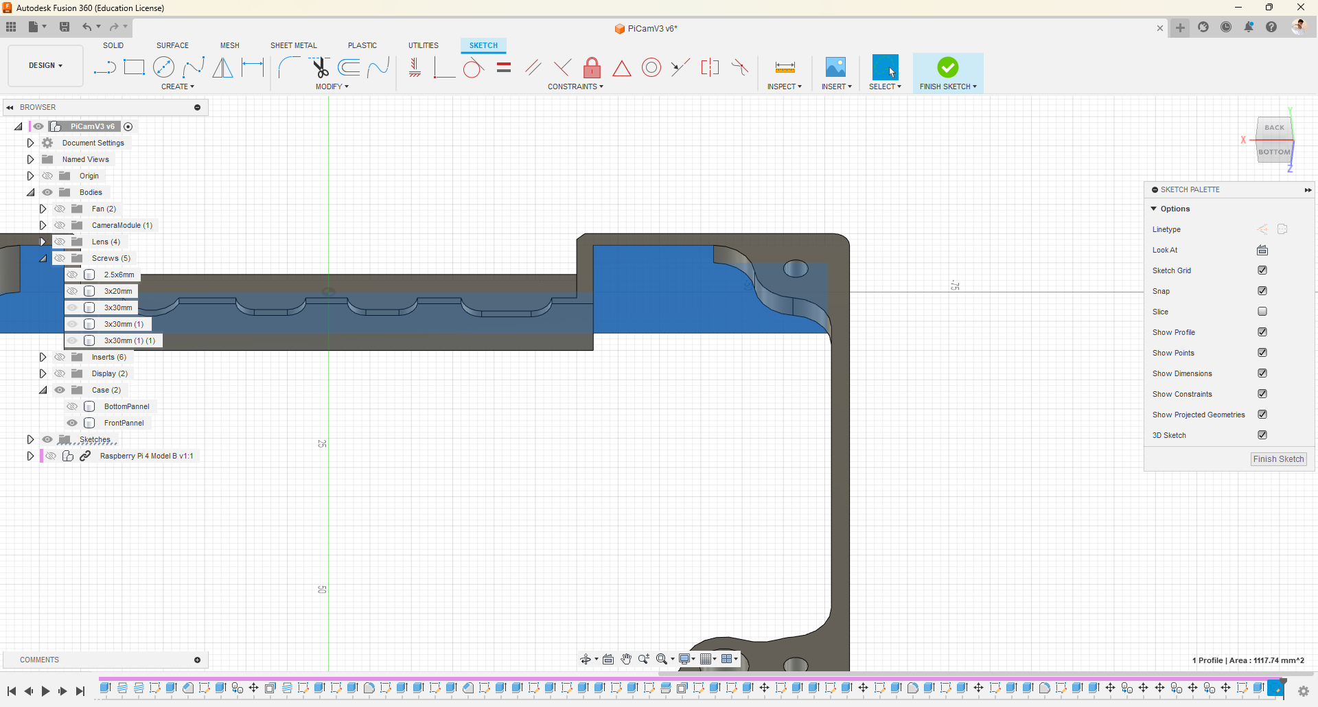
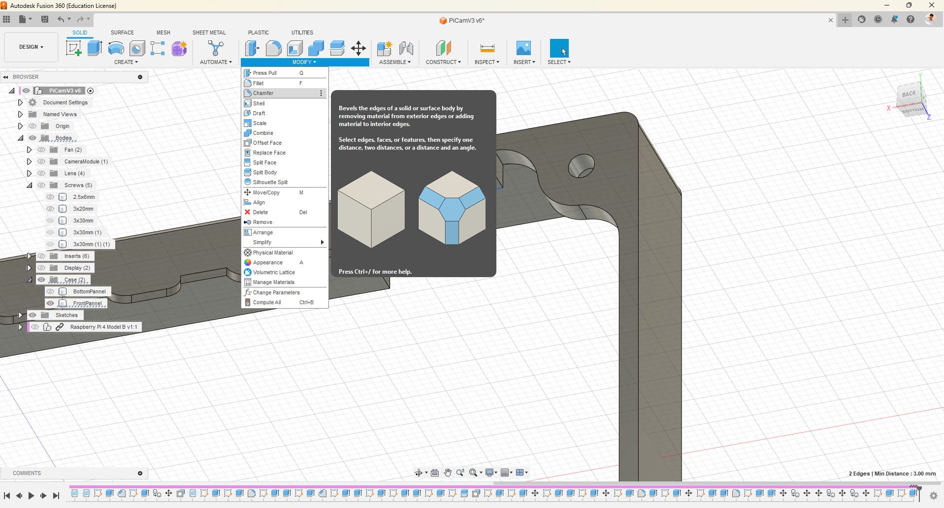
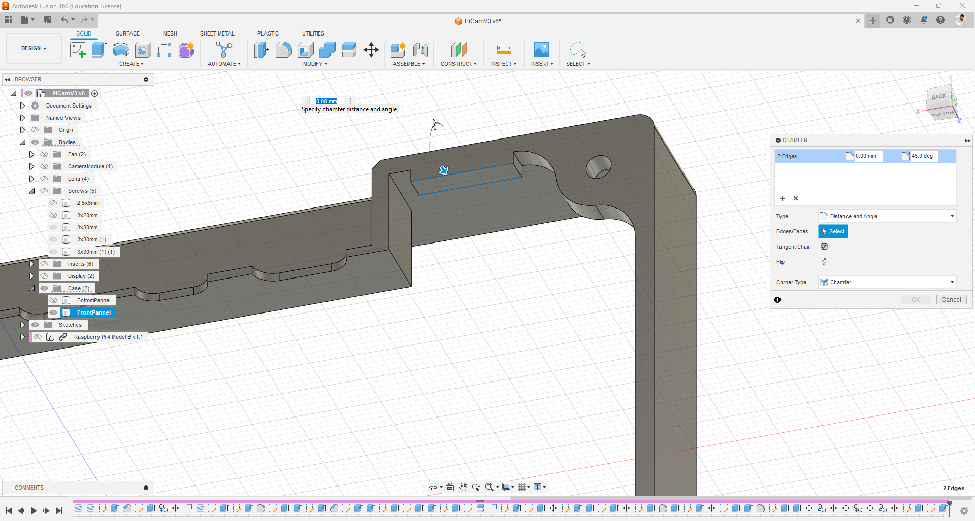
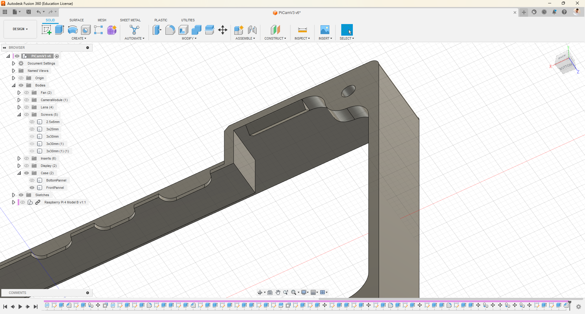
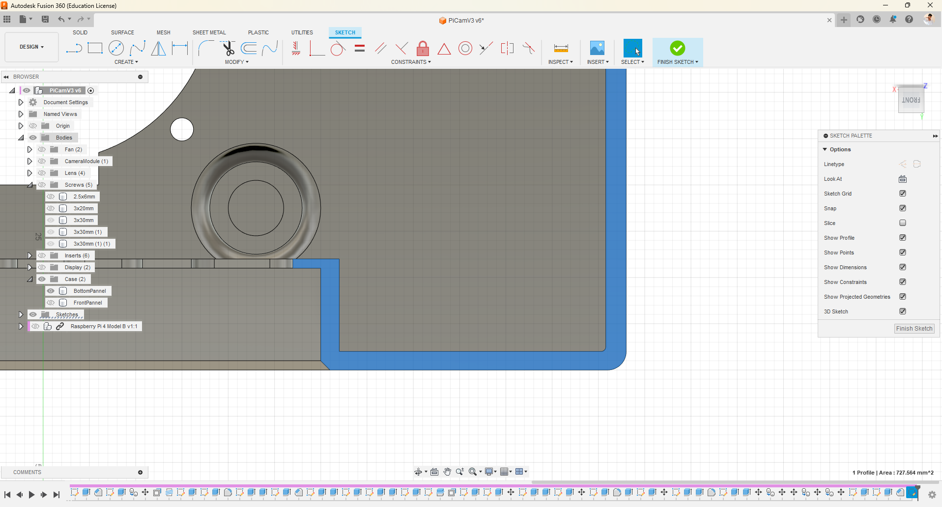
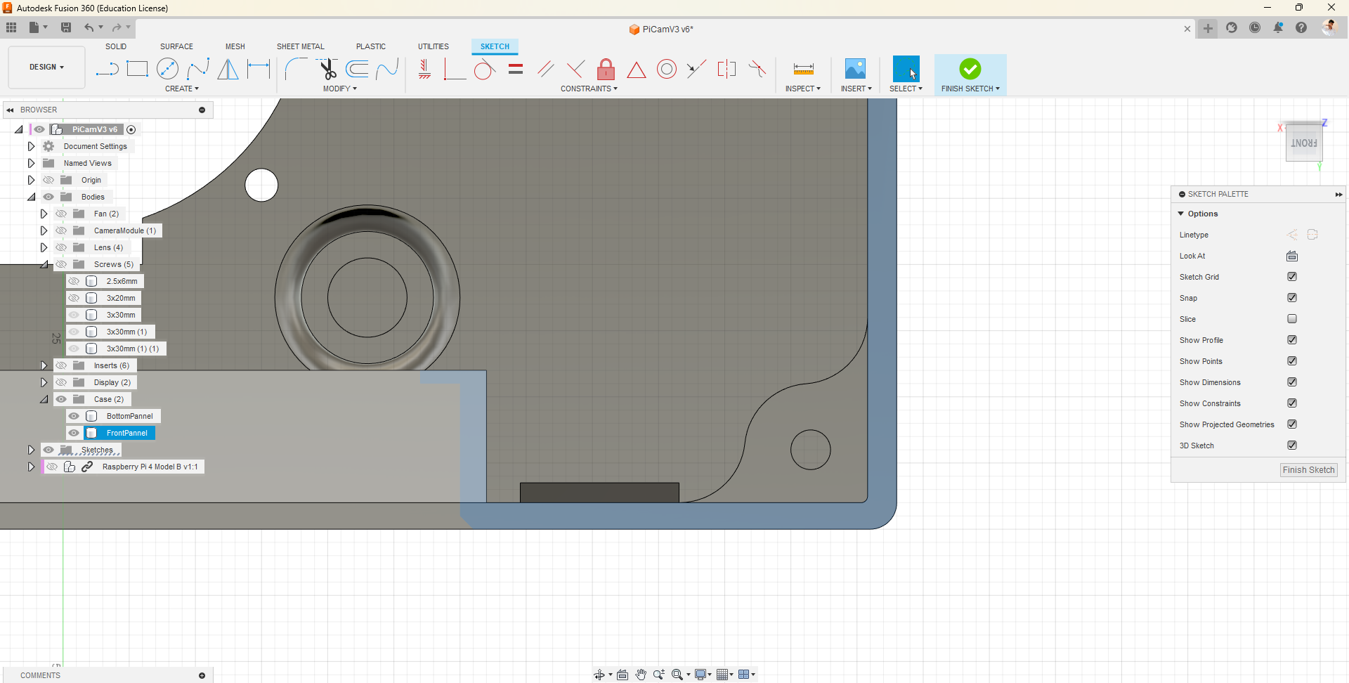
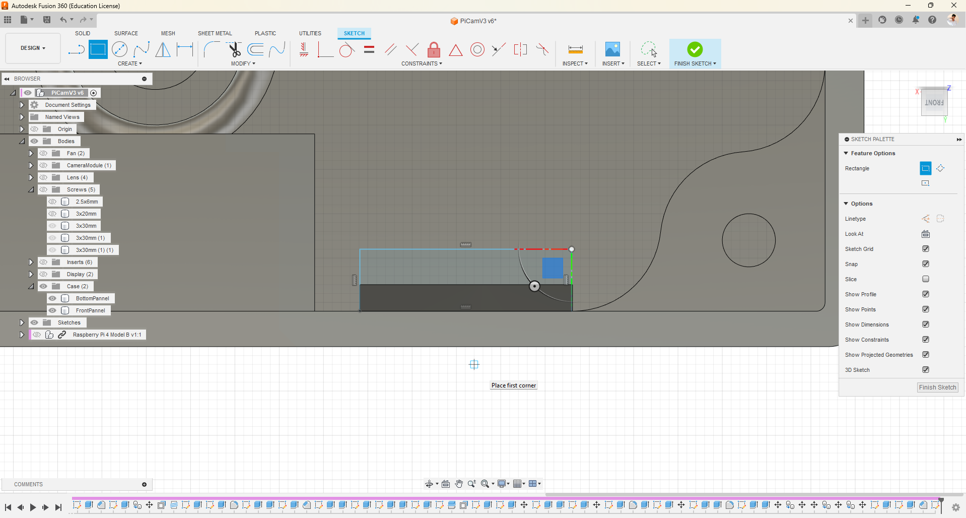
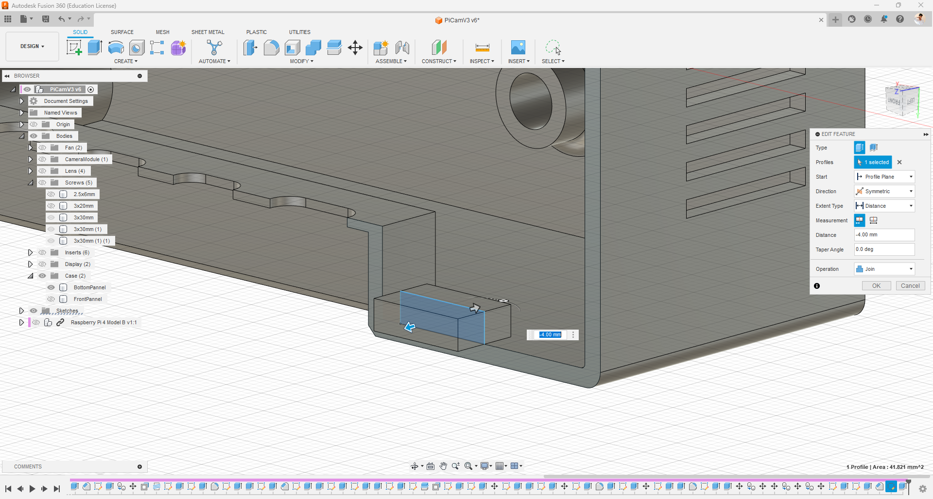
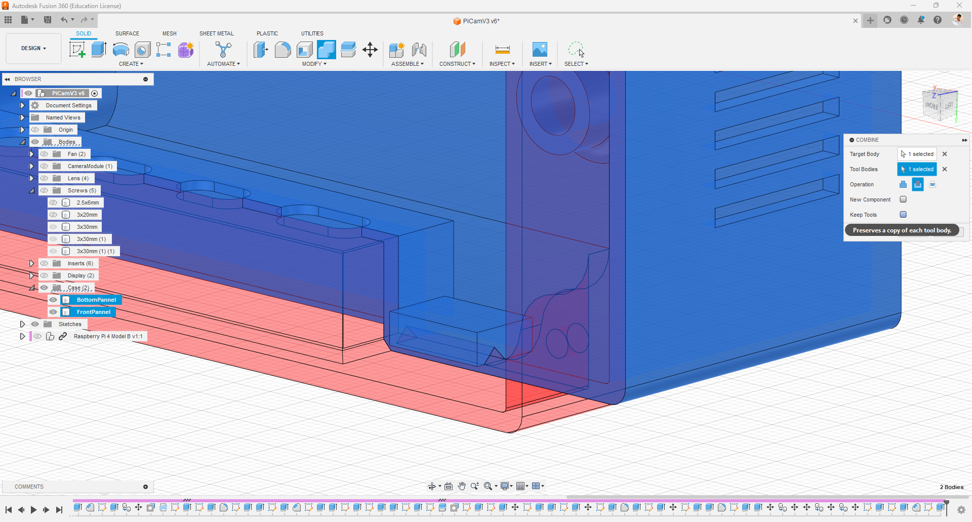
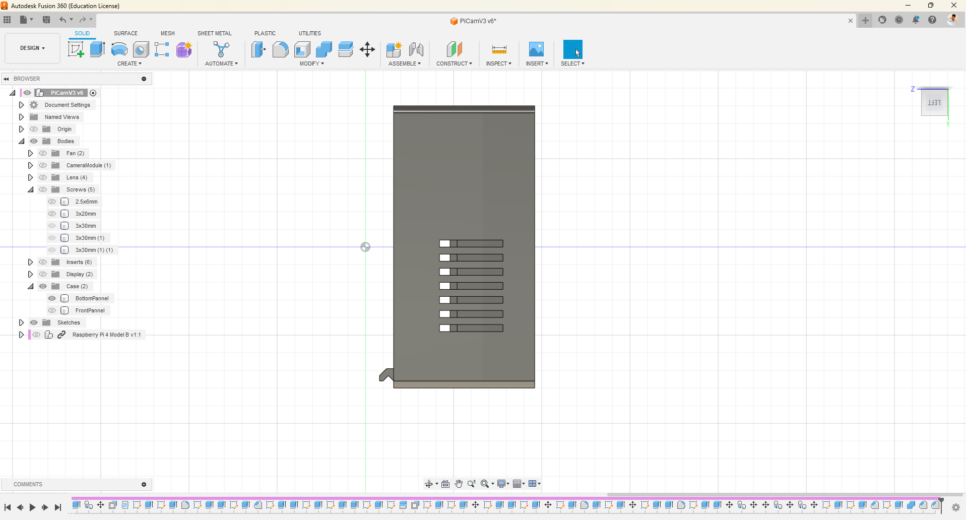
- Since we didn't have room for the 4th screw I desisted to use snap mechanism to lock the two Pieses together.
- In this case, I utilized two new features in Fusion 360 called chamfer and combine. With combine we can either cut one body into another or just join(combine) two bodies together.
- You can follow snap fit tutorial to use it in your projects.
How Can We Eliminate Support When 3D Printing
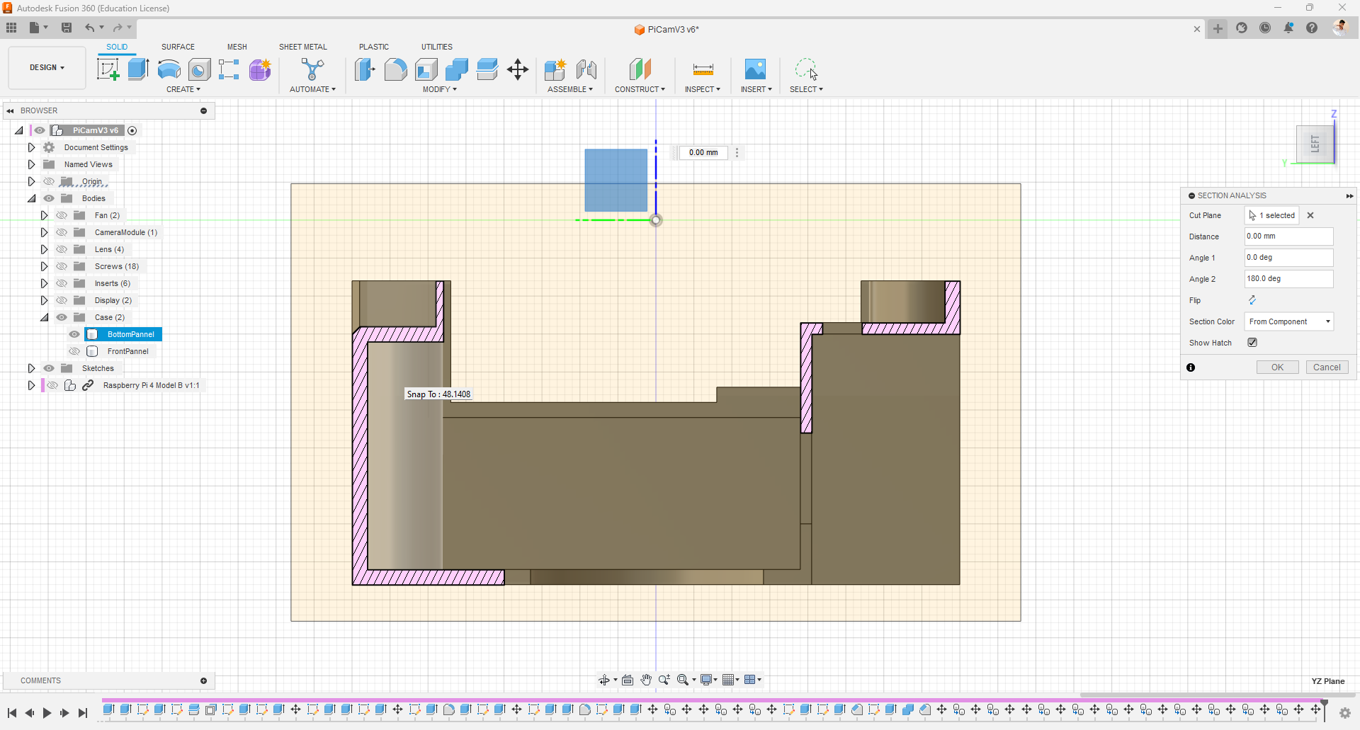
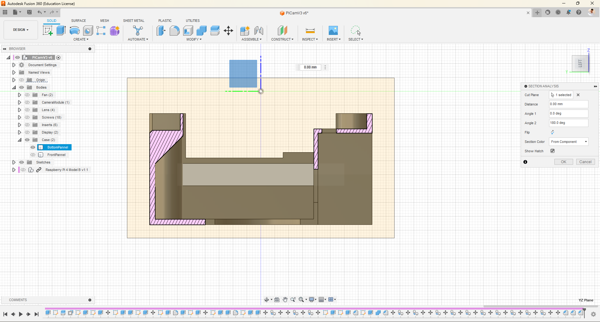
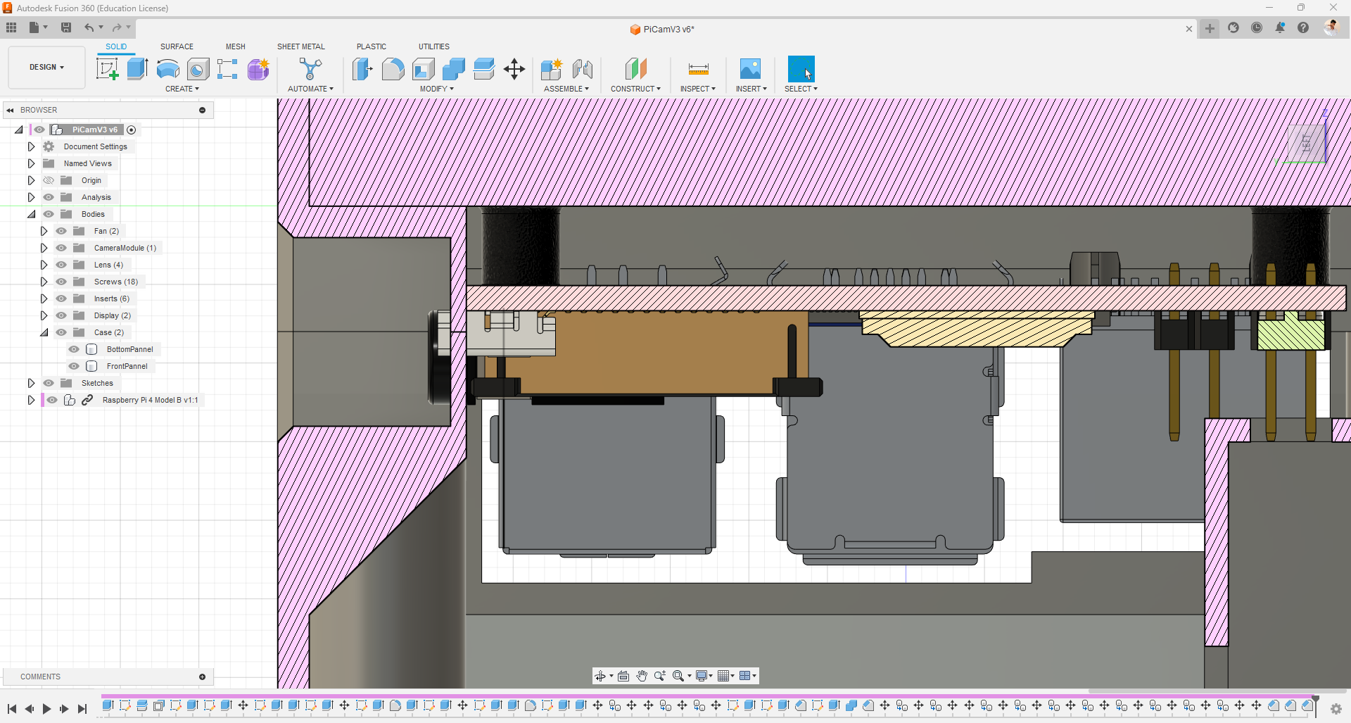
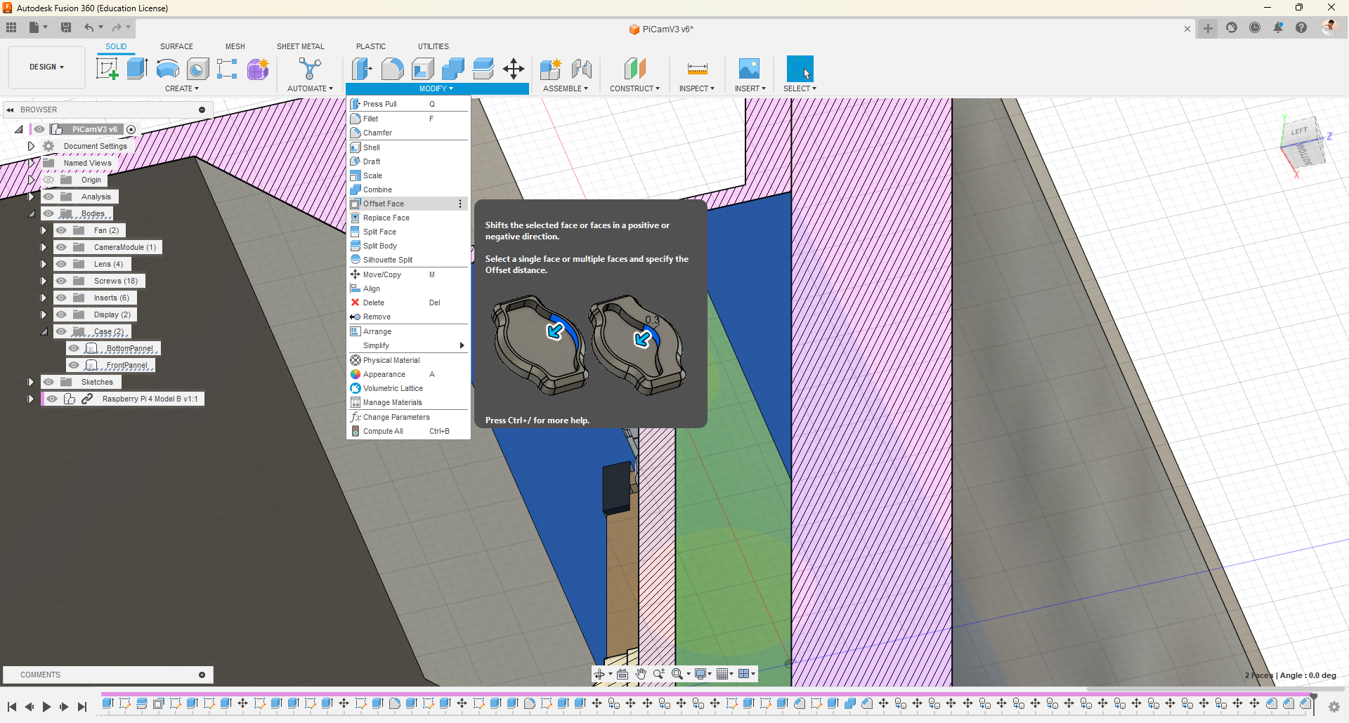
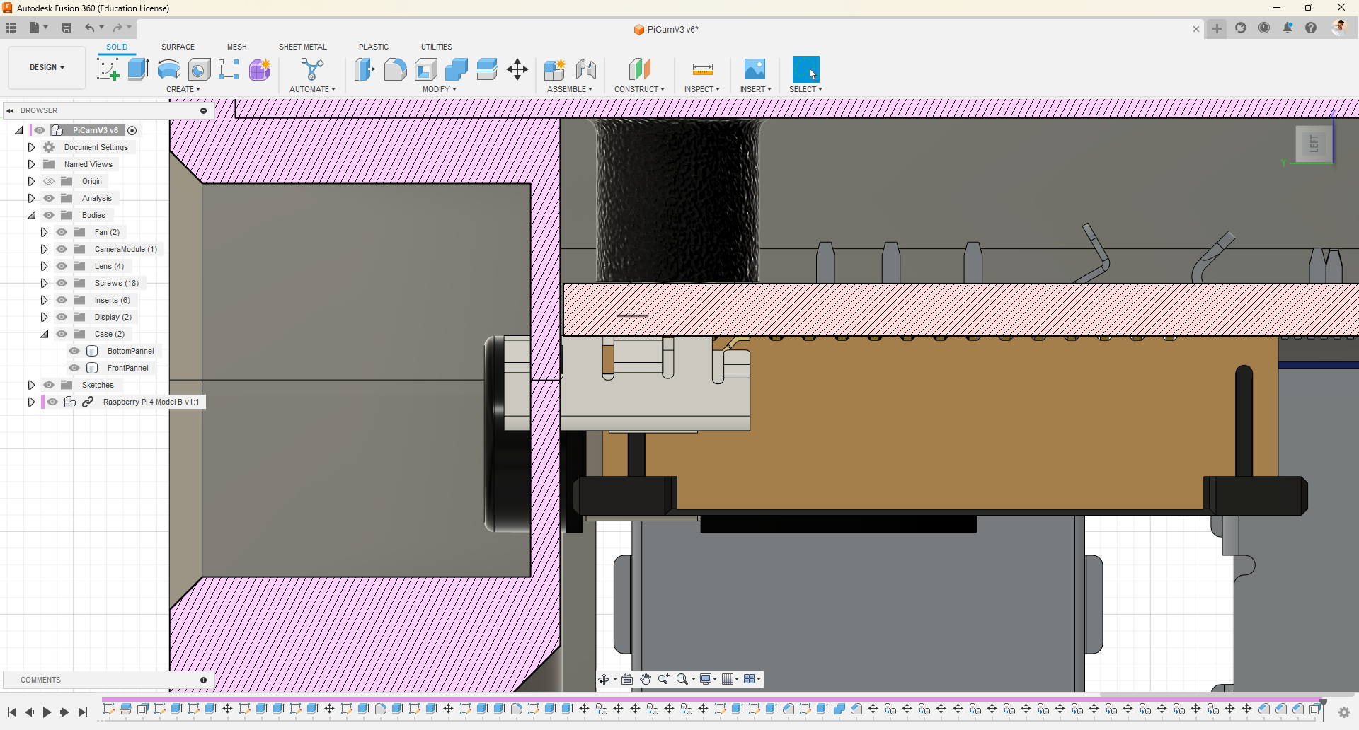
- By performing a section analysis, we can observe that there are several surfaces with overhangs.
- Consequently, during 3D printing, it becomes necessary to utilize supports to prevent deformation.
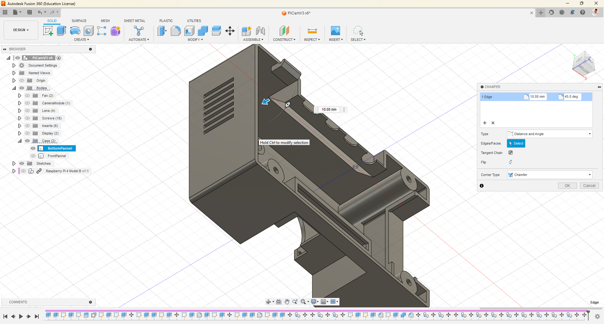
- However, by incorporating a 45-degree chamfer, we can eliminate the need for supports.
- This approach not only allows us to save on material but also eliminates the challenge of removing supports from inaccessible areas.
Final Touchup
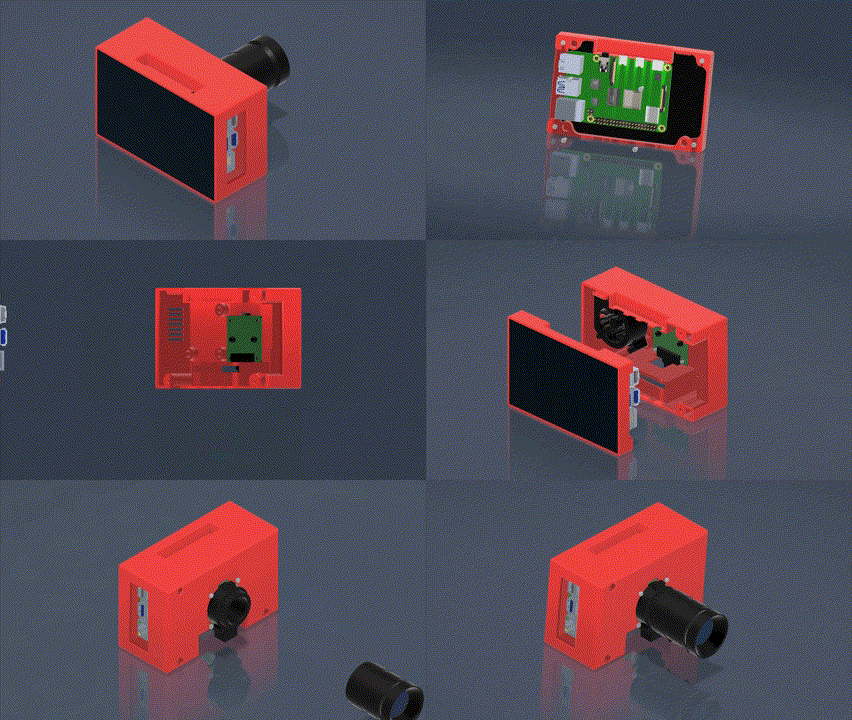
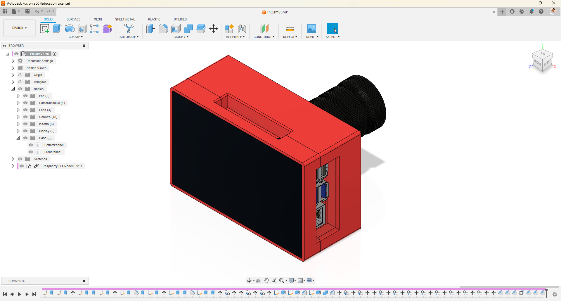
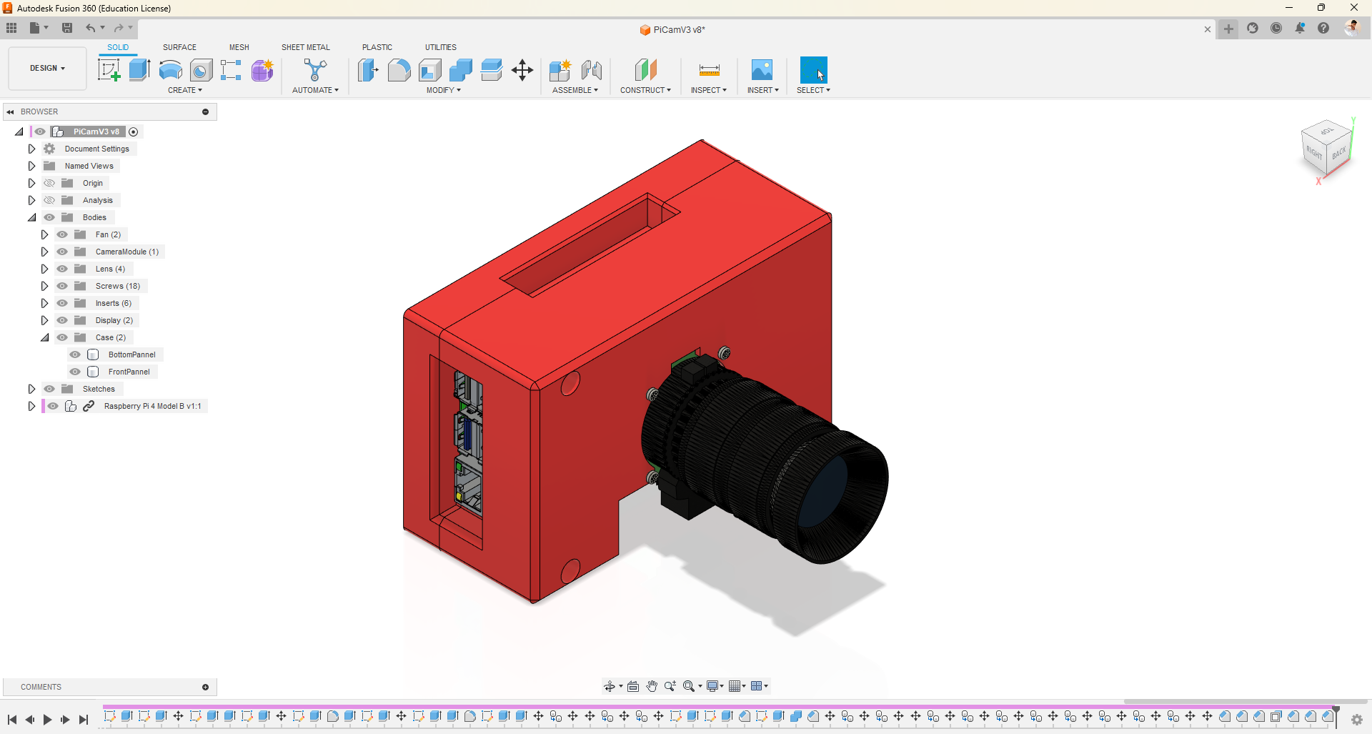
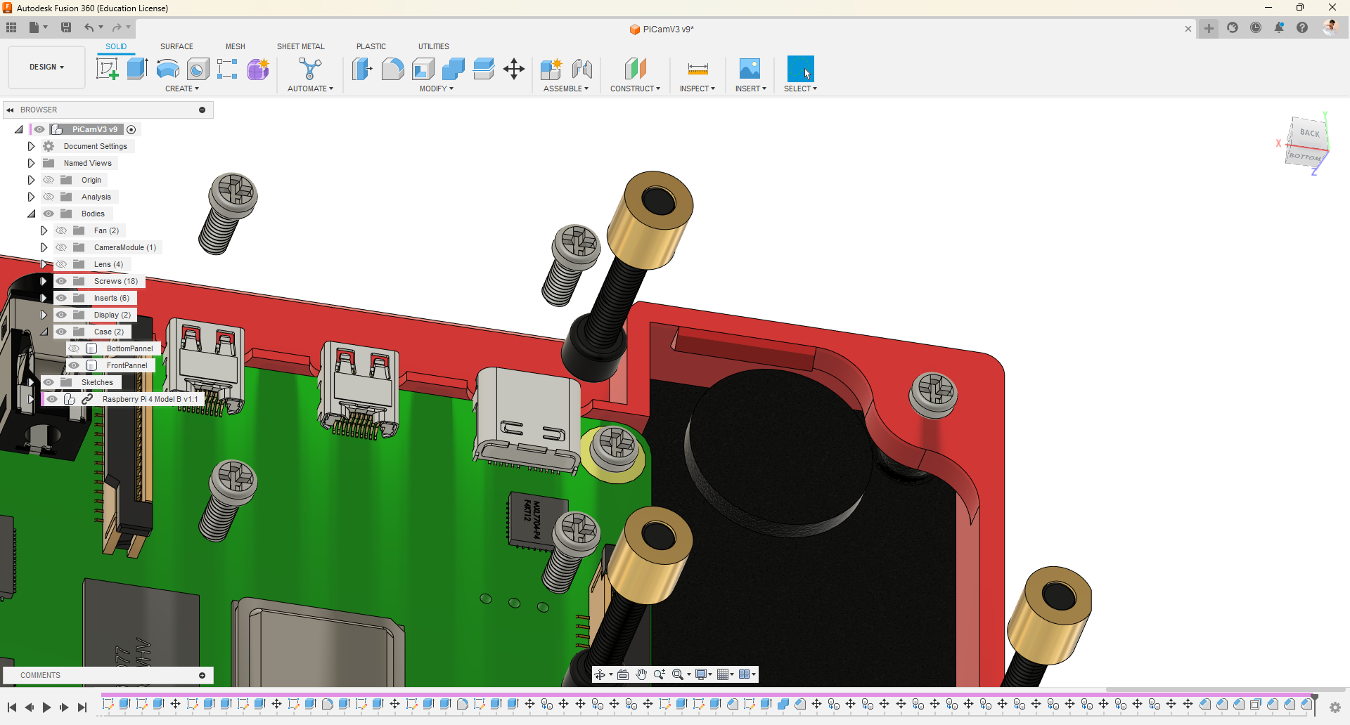
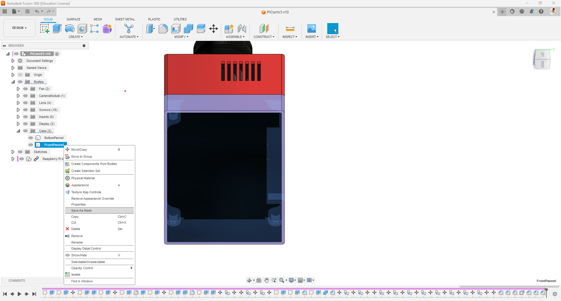
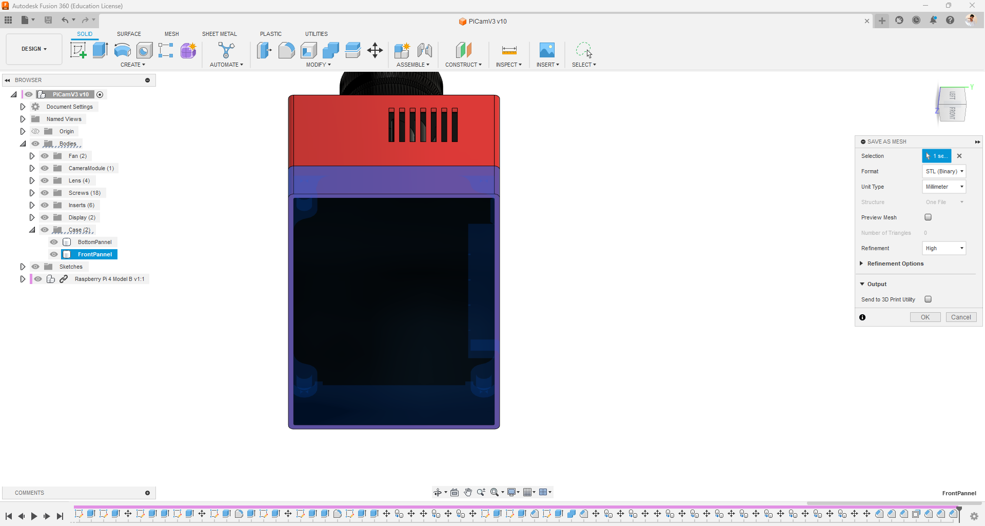
- Finally I just put the materials to remaining components and placed screws and inserts in their respective positions.
STL Export:
- Select the component or body you want to export as an STL file. If you want to export the entire design, make sure nothing is selected.
- Click on the "File" menu in the top-left corner of the Fusion 360 window or just right click.
- Choose the "Export" option from the drop-down menu, and then select "CAD Format."
- In the export dialog box, choose "STL" as the file format.
- Specify the desired export options such as units, refinement, and mesh density. Adjust these settings based on your specific requirements.
- Provide a name and choose a location on your computer where you want to save the STL file.
- Click on the "OK" button to start the export process.
3D Printing
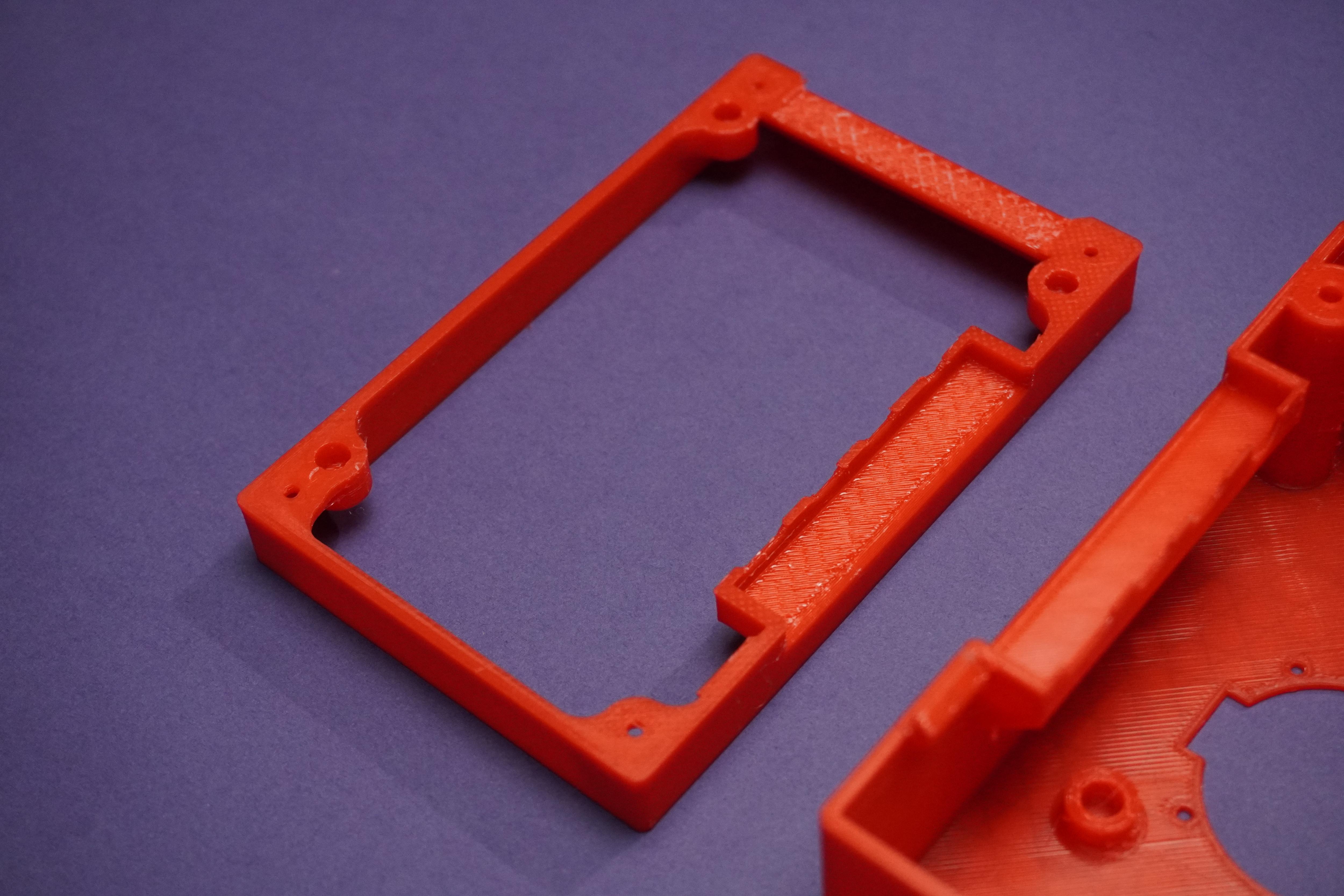
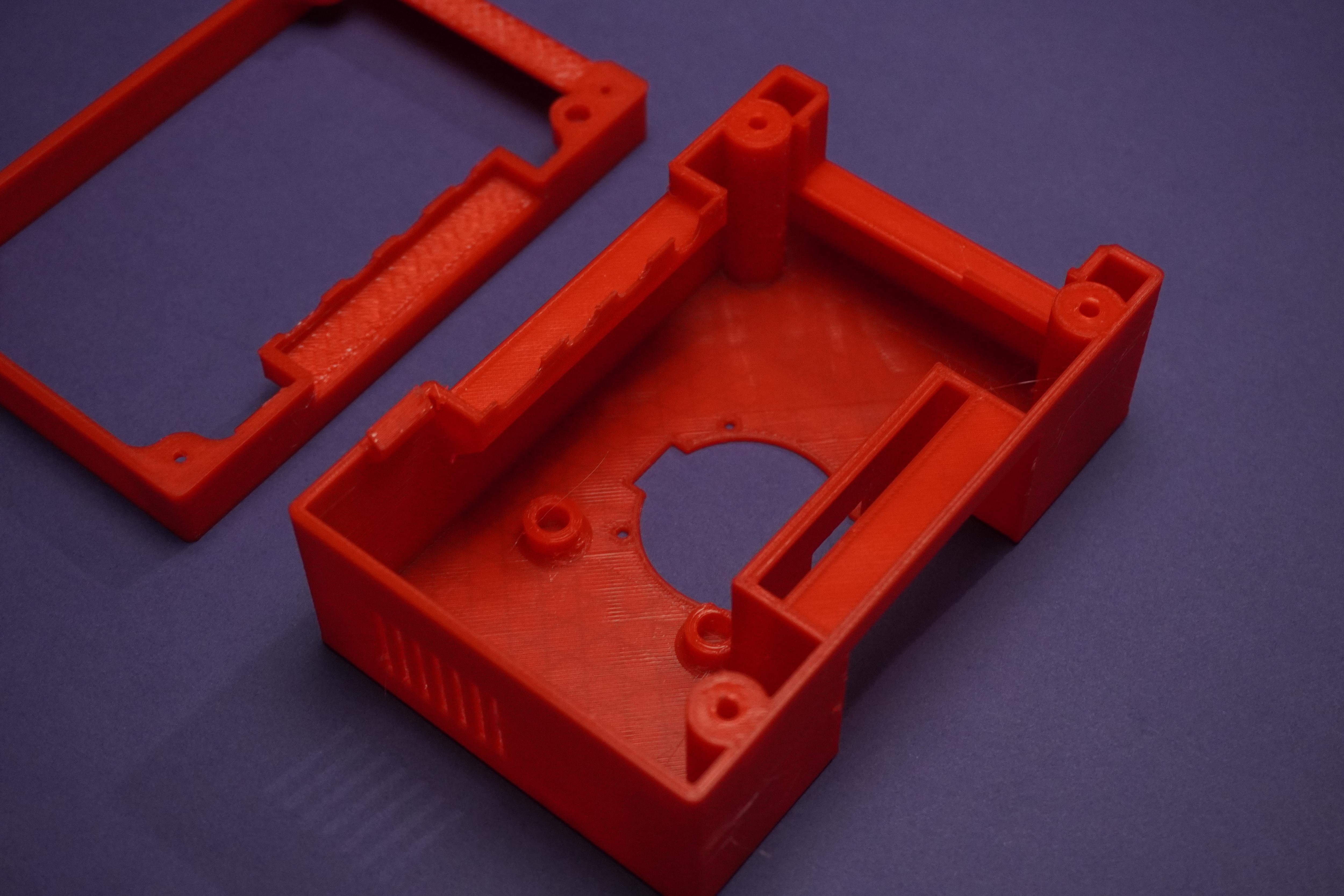
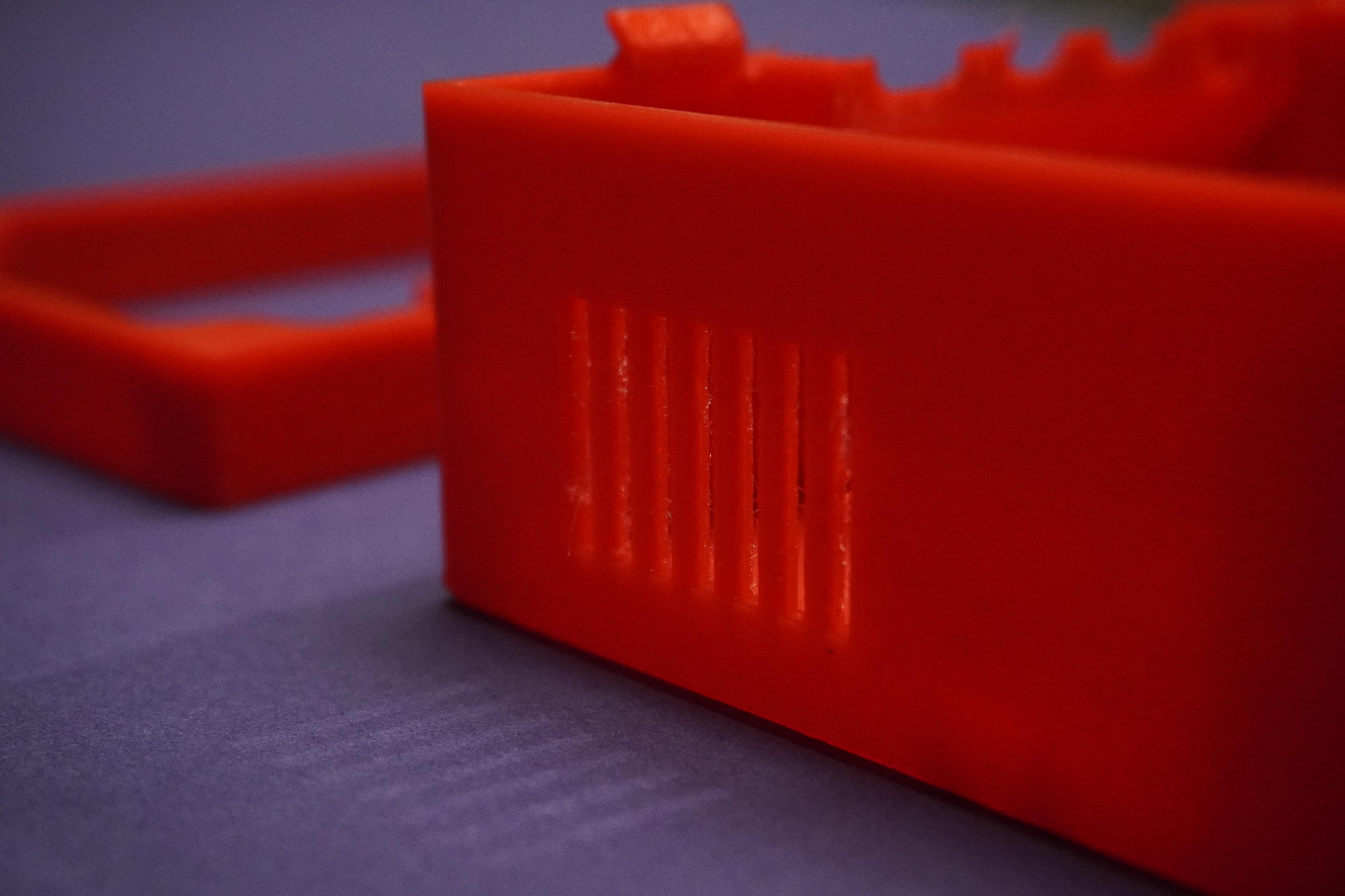
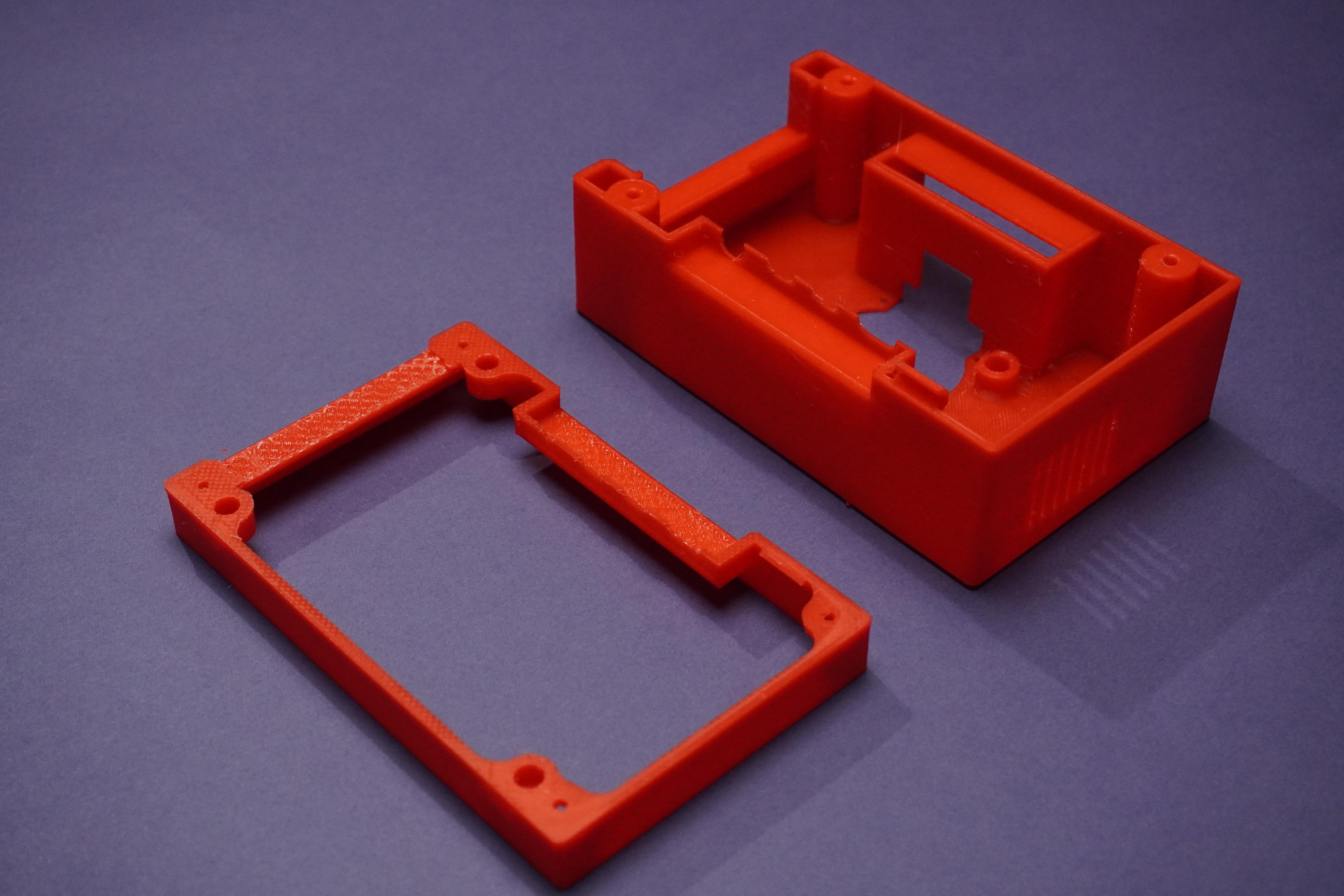
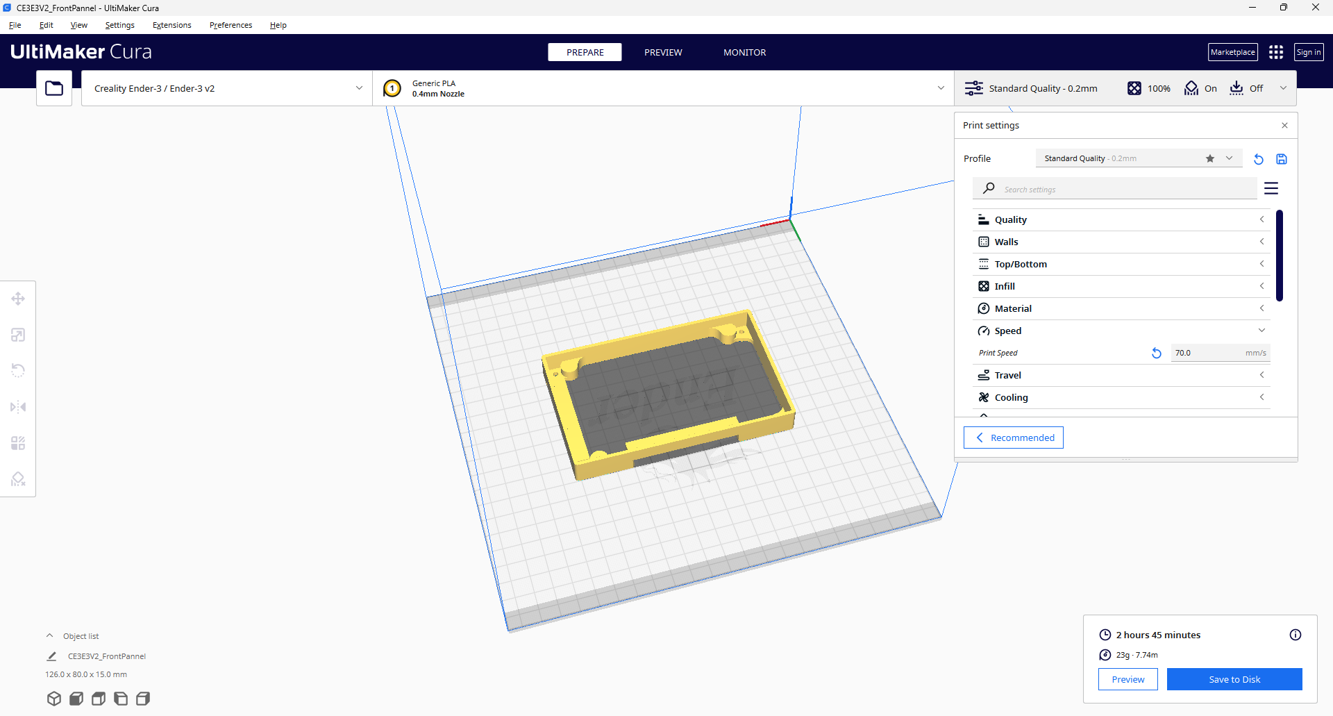
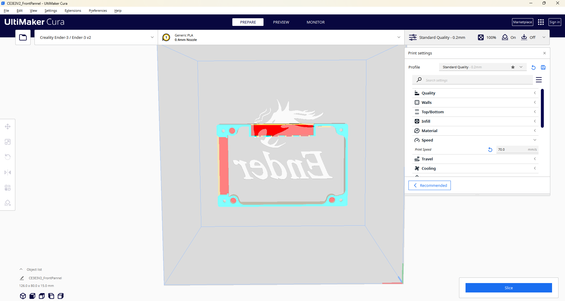
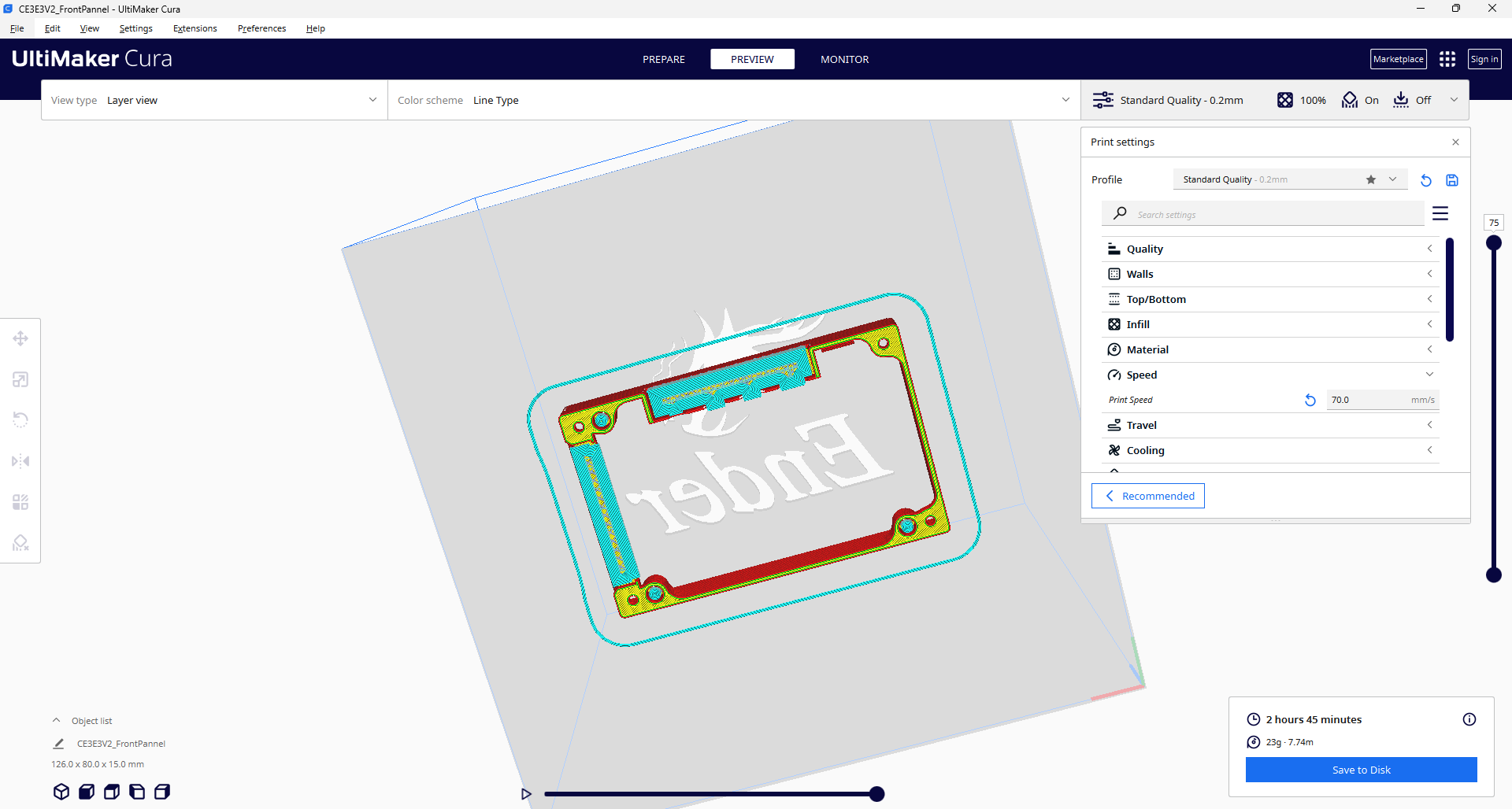
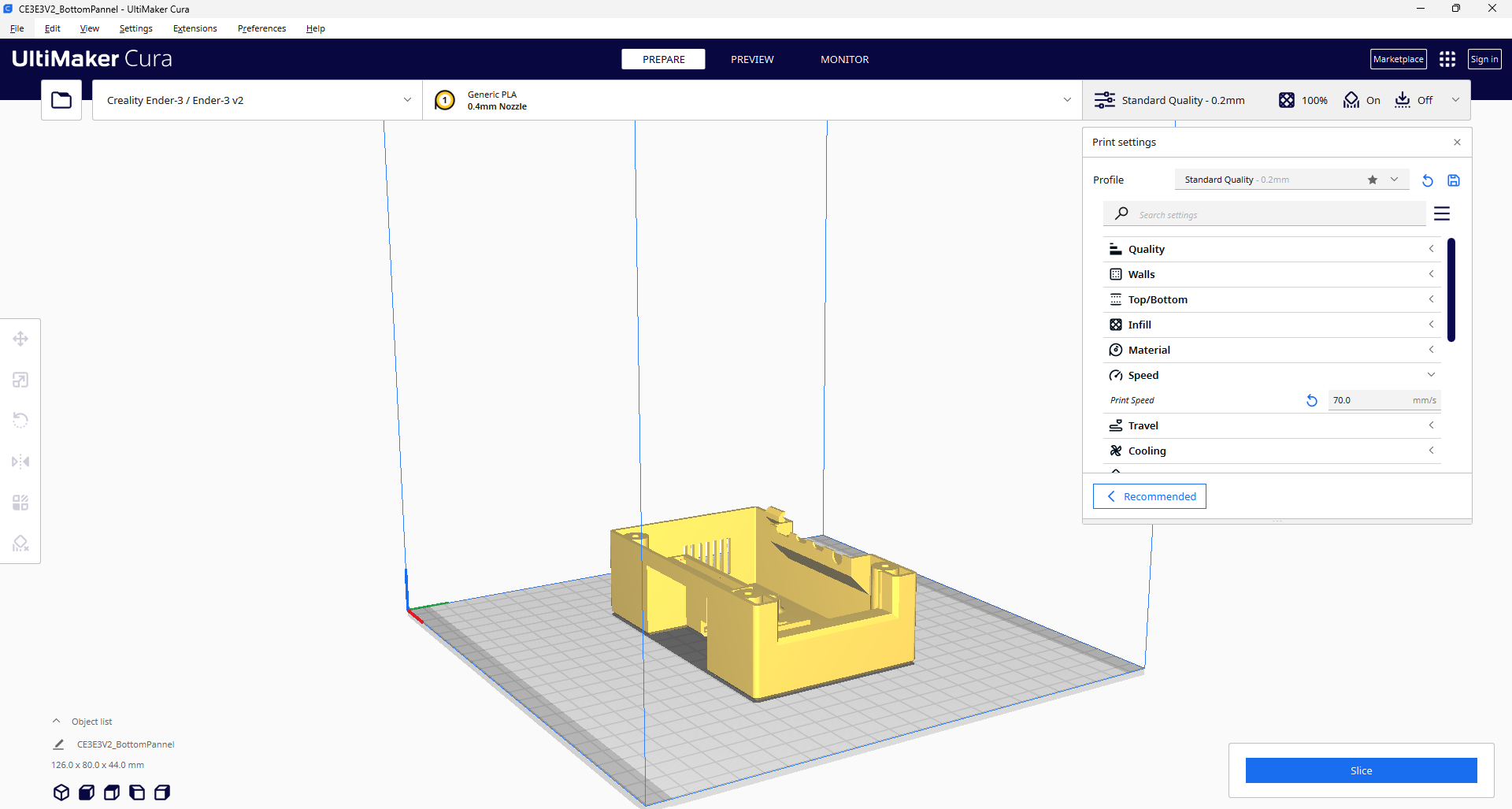
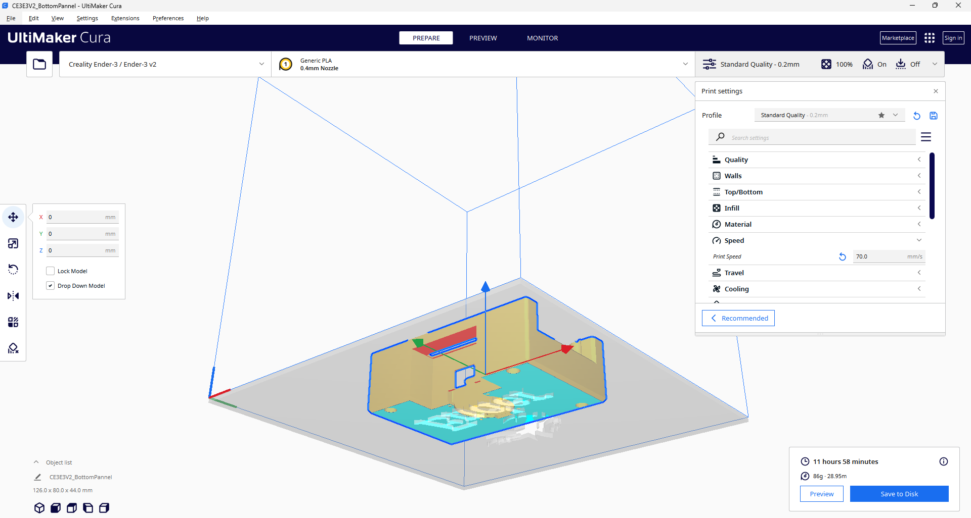
- After exporting the stl files open them in Cura software, slice them and 3D print them.
Or
- My stl files:
You don't have 3D Printer? Not to worry!
Here I would recommend getting it done from PCBWAY
Why them? They provide the best 3D Printing Service and The quality is just amazing compared to other providers in the market
Its definitely the right time to use their service as they are raining offers due to 9th-anniversary check offers here https://www.pcbway.com/activity/anniversary9sales.html
Free coupons, Anniversary sales, and blind boxes are live, Checkout the free coupons they are offering upto 200$
Don't miss to check their blind boxes, with this game you can try your luck by participating in their lucky draw.
How to play? Just click here and open any of the boxes! also, earn coupons by sharing the links with your friends, refer the last visual of this step for the same
Get your 3D Printed parts from here https://www.pcbway.com/rapid-prototyping/
Assembly Part-1
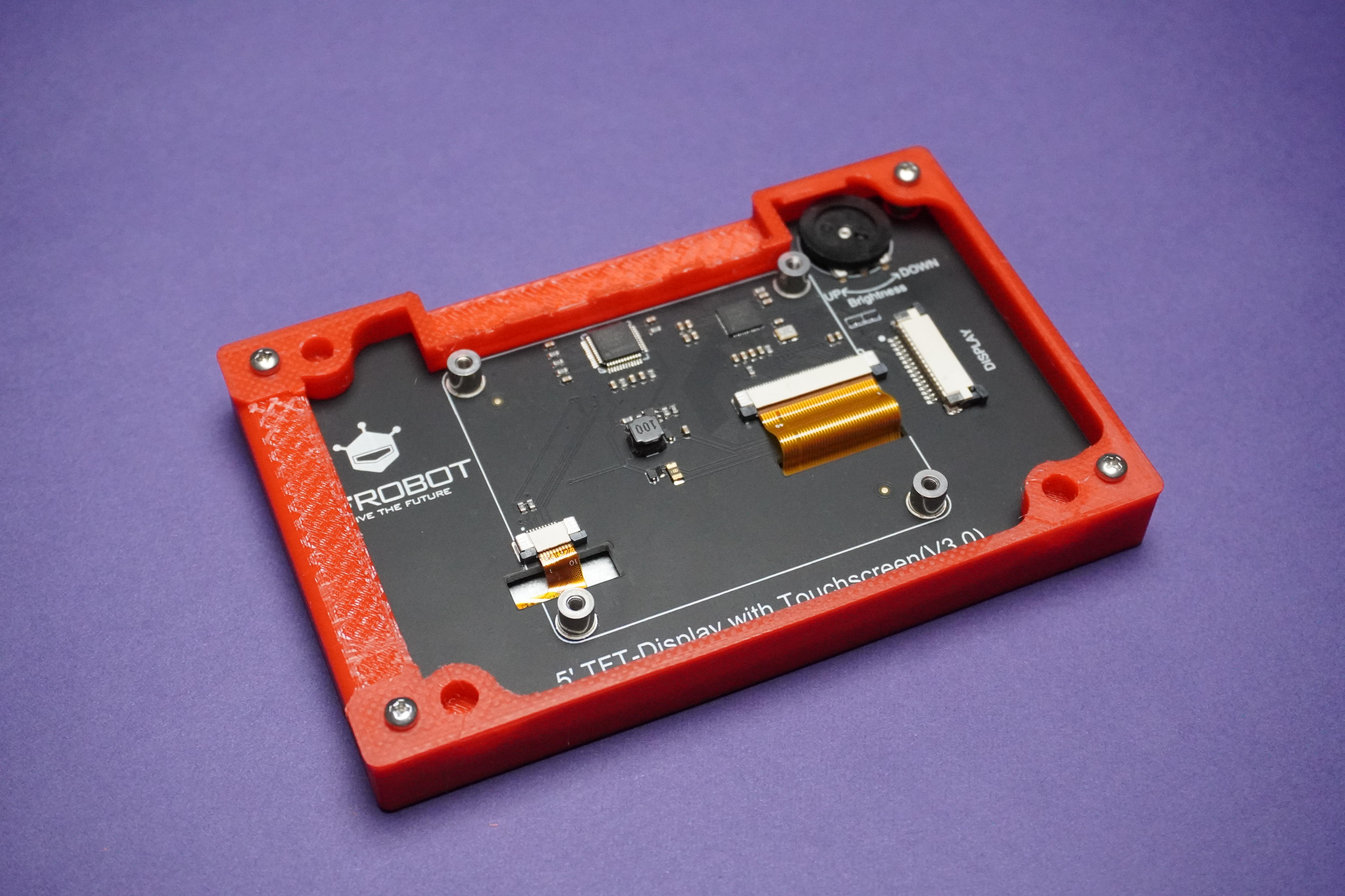
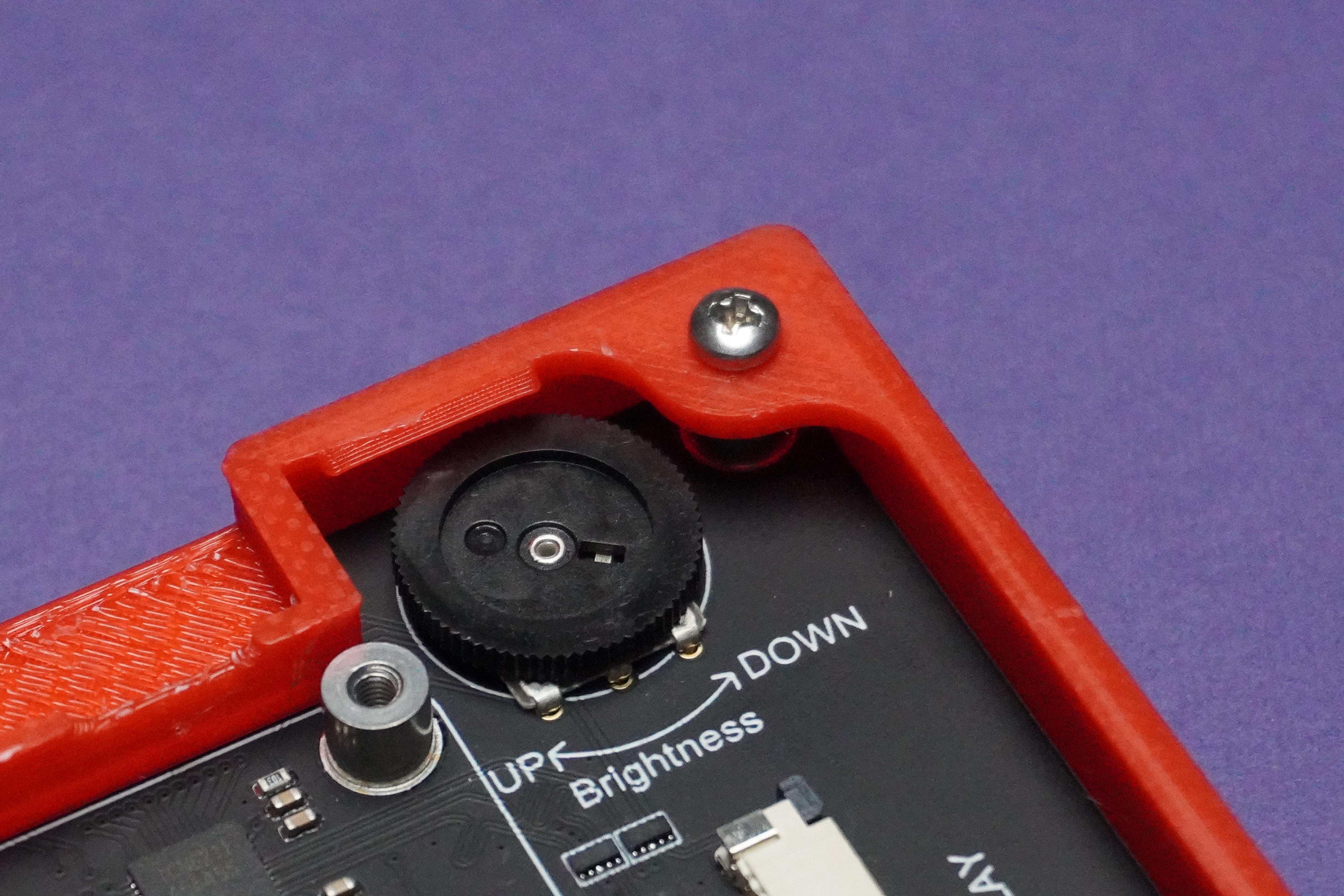
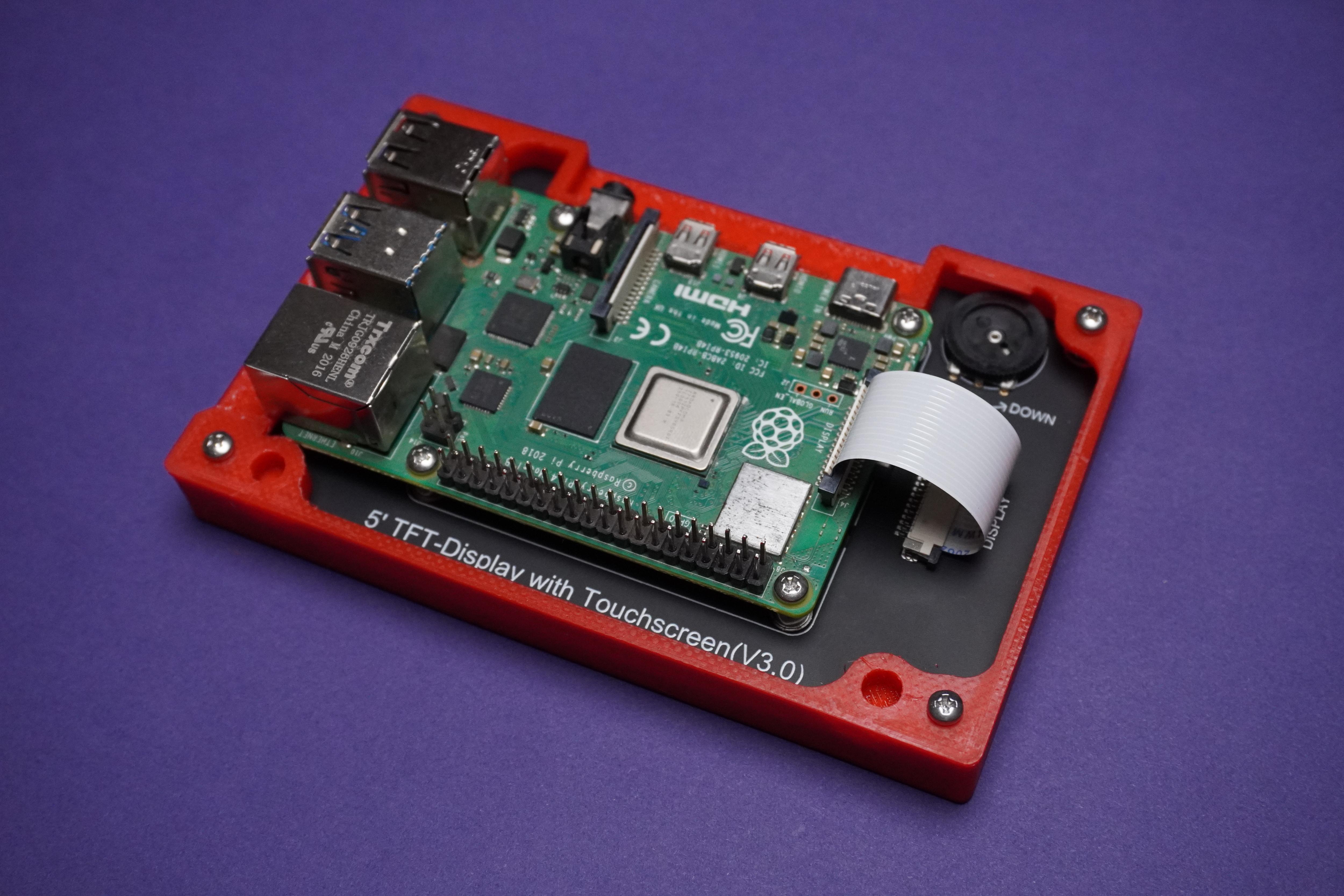
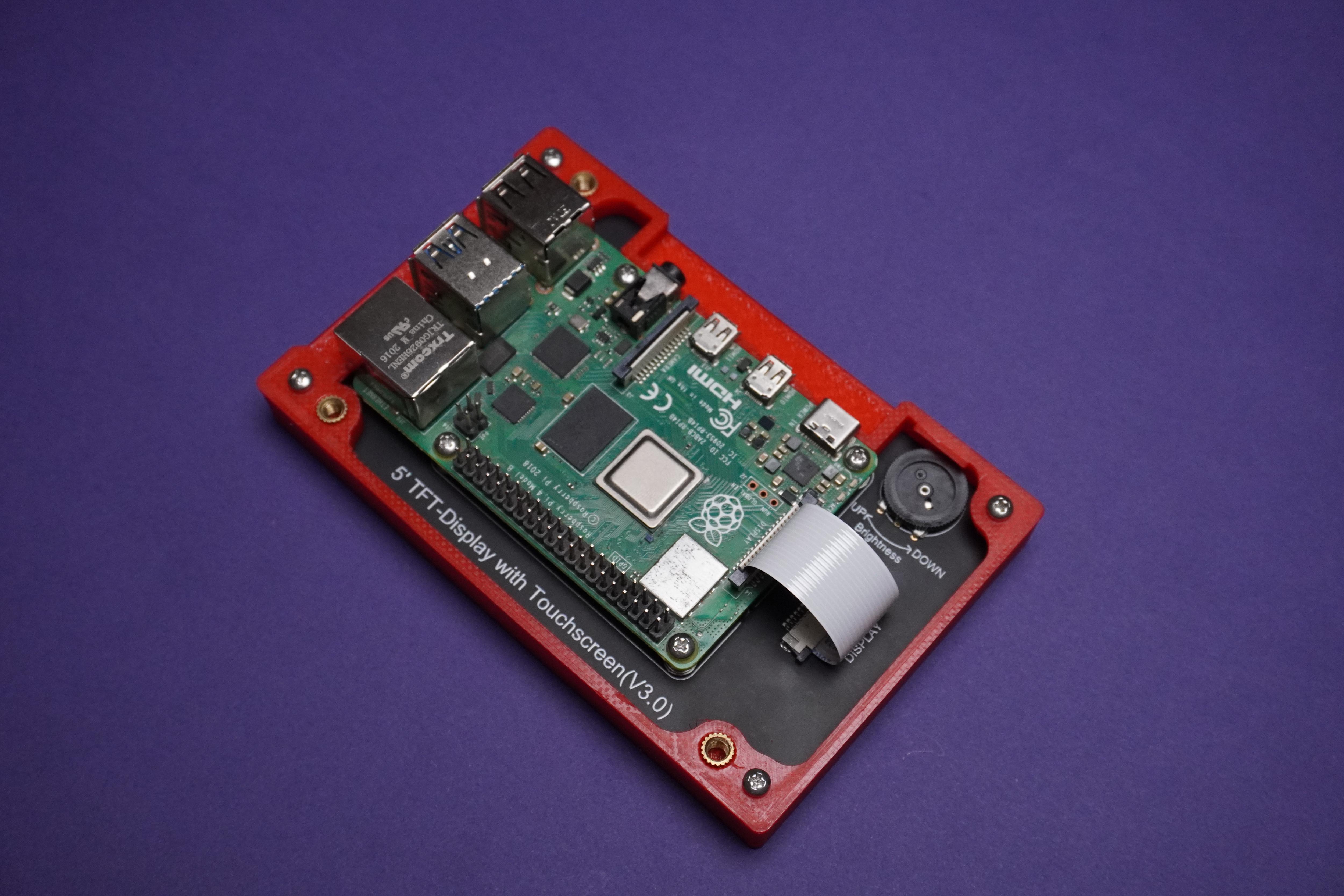
- Put the display into front panel with M2.5 Screws.
- Install the Raspberry Pi Operating System on to SD card using Raspberry Pi Imager Software and insert it into Raspberry Pi.
- I am using Raspberry Pi OS(32-bit) Recommended by the software.
- Then put Raspberry pi onto the screen using screws and connect the display cable that came in the box.
How to Use Metal Inserts in 3D Printed Parts
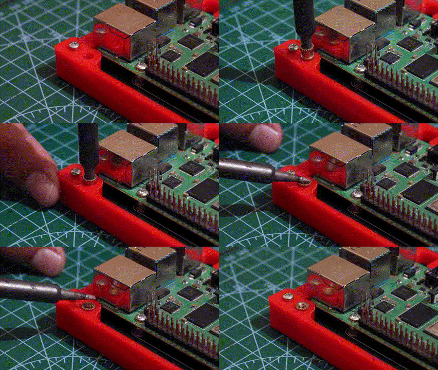
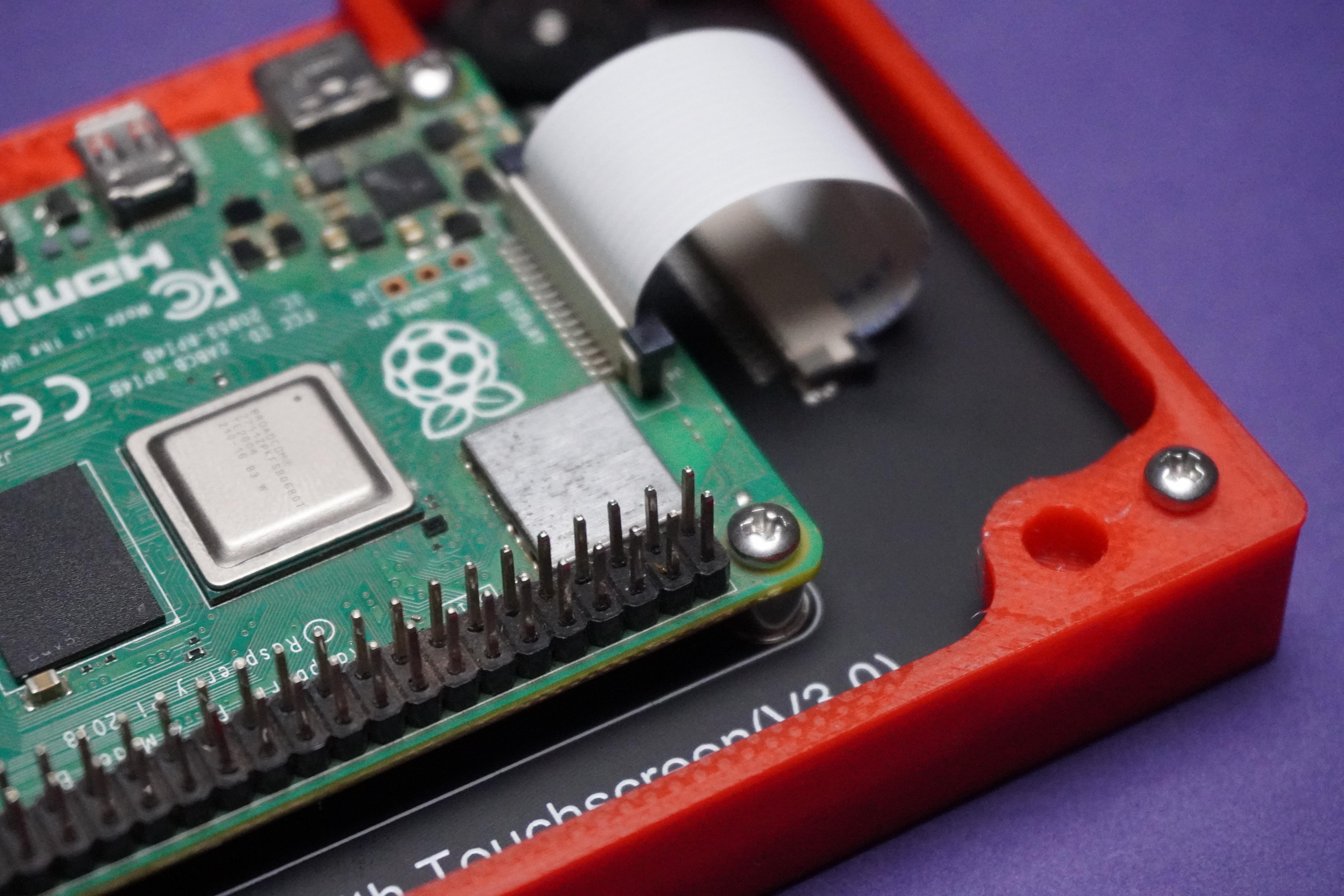
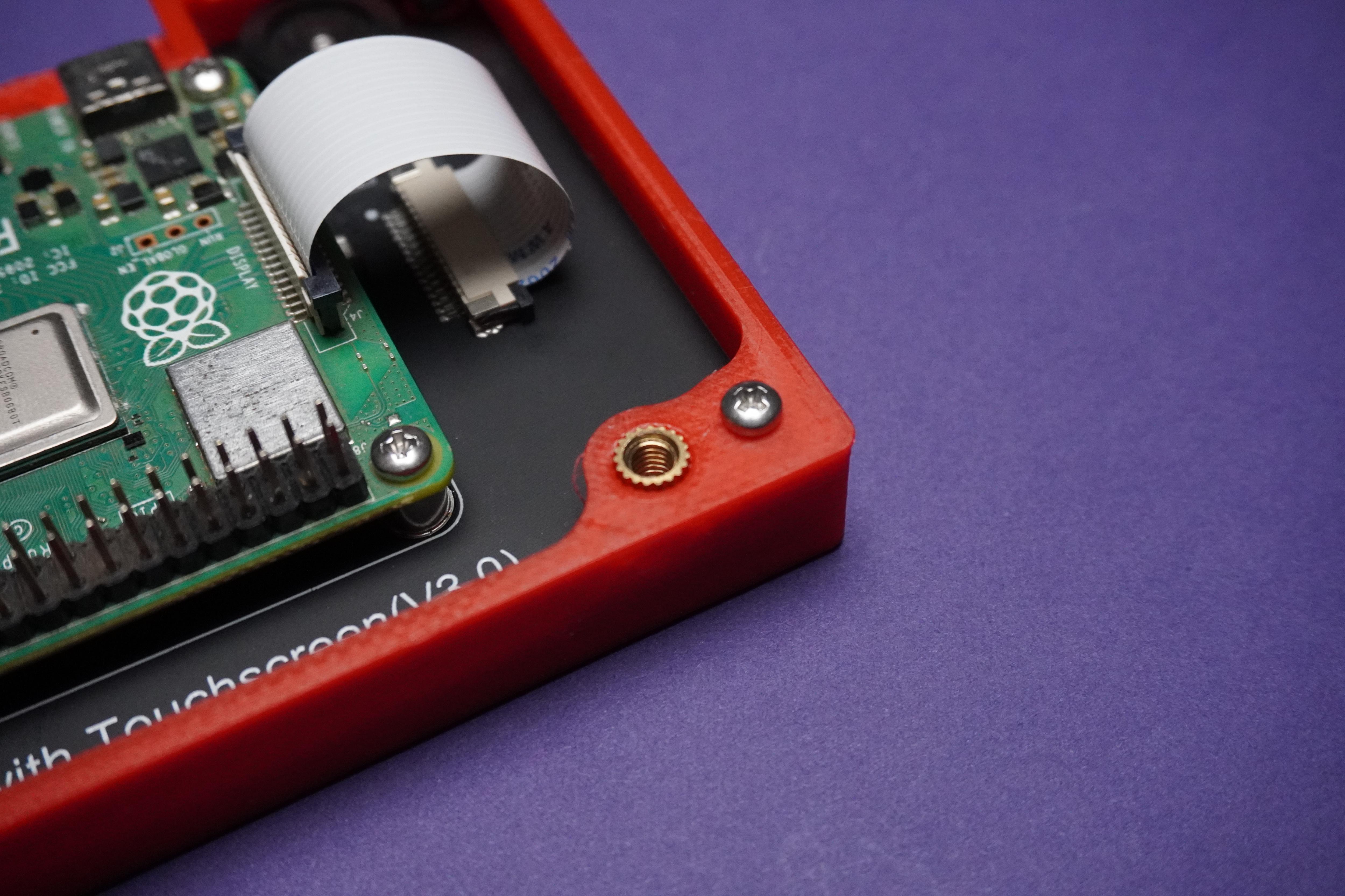
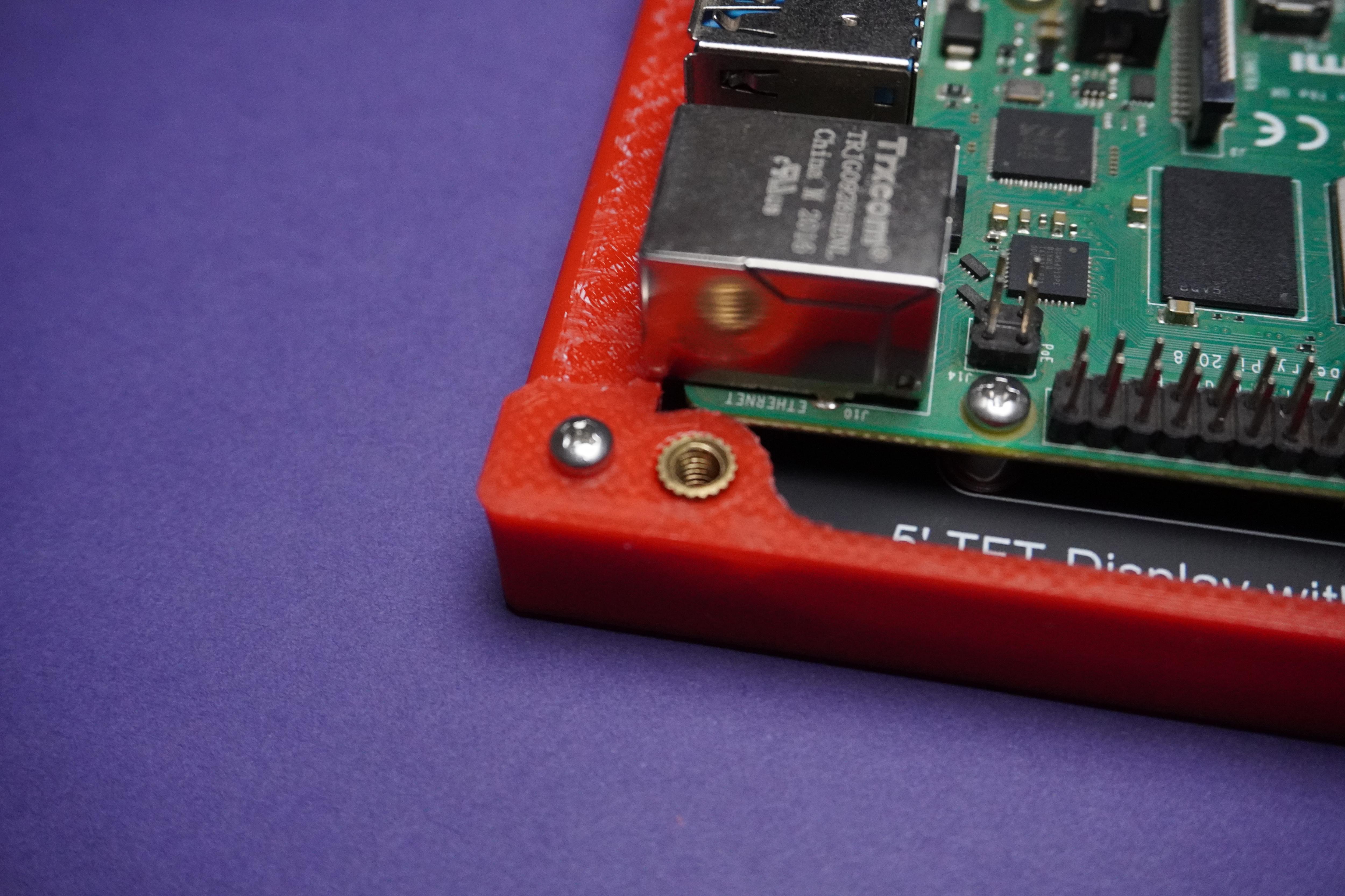
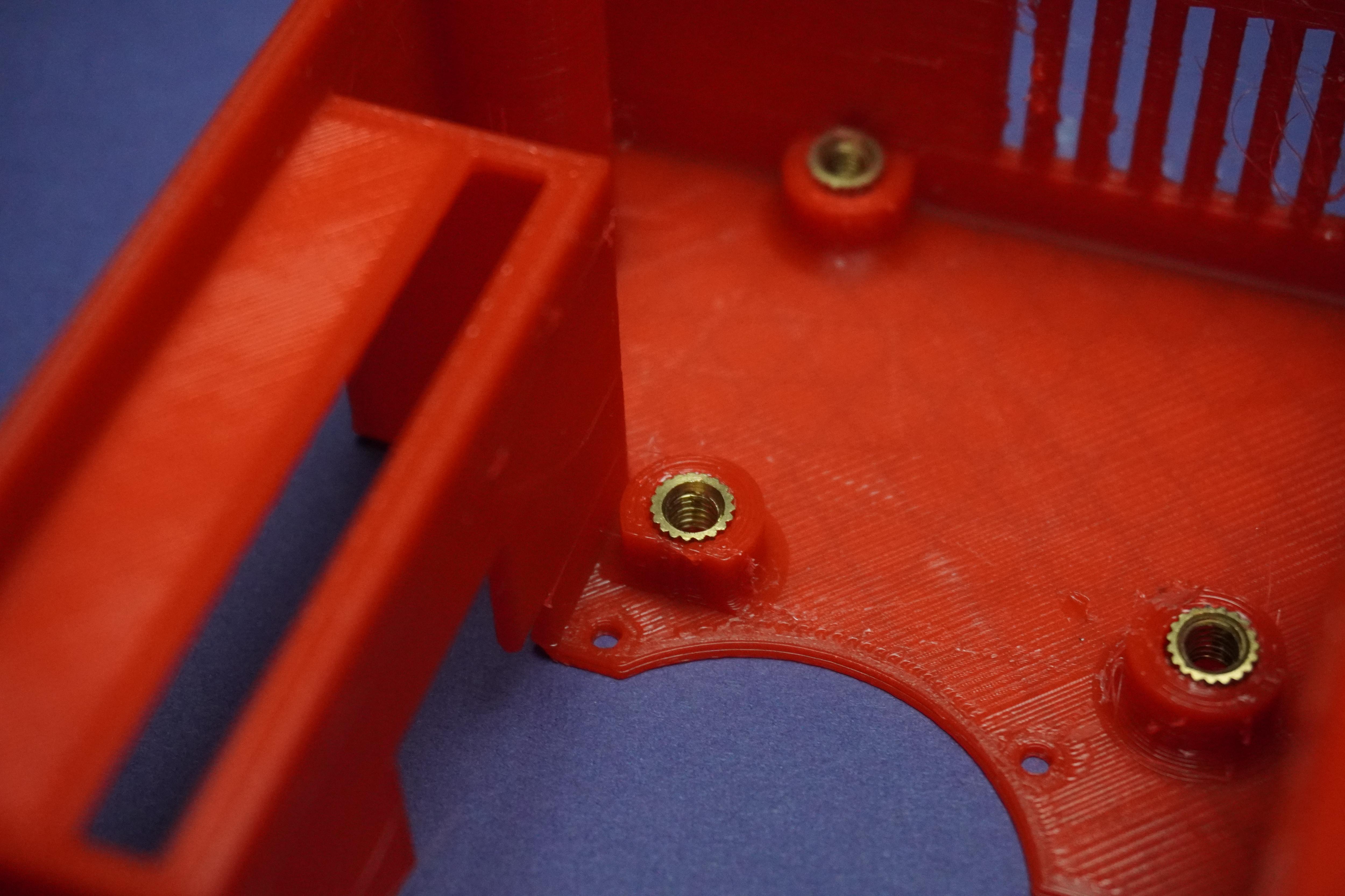
- This step should be done before(Step 20) we installed display and raspberry pi.
- Using soldering iron I heated the metal inserts and inserted them into my 3D prints.
Assembly Part-2
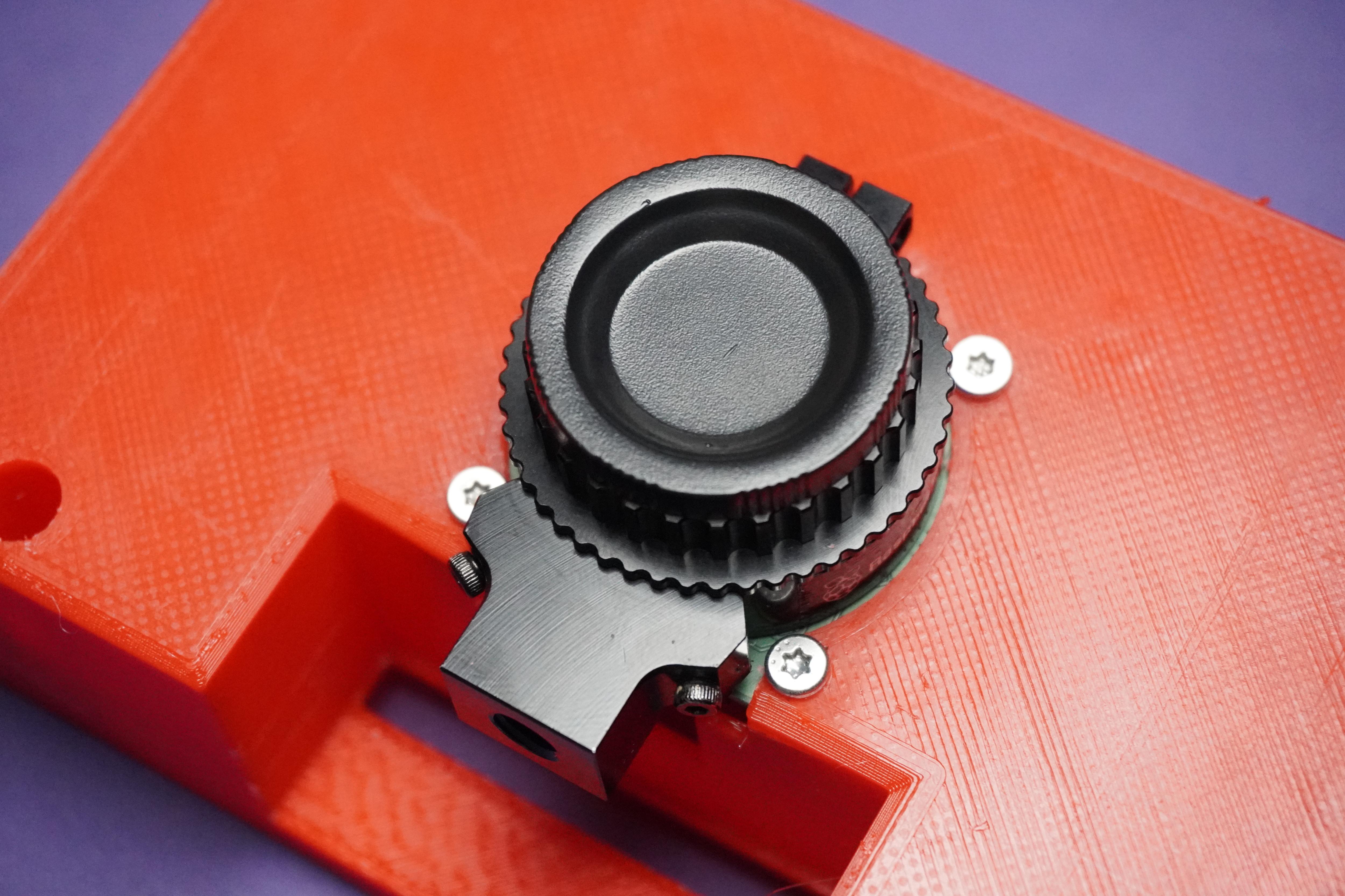
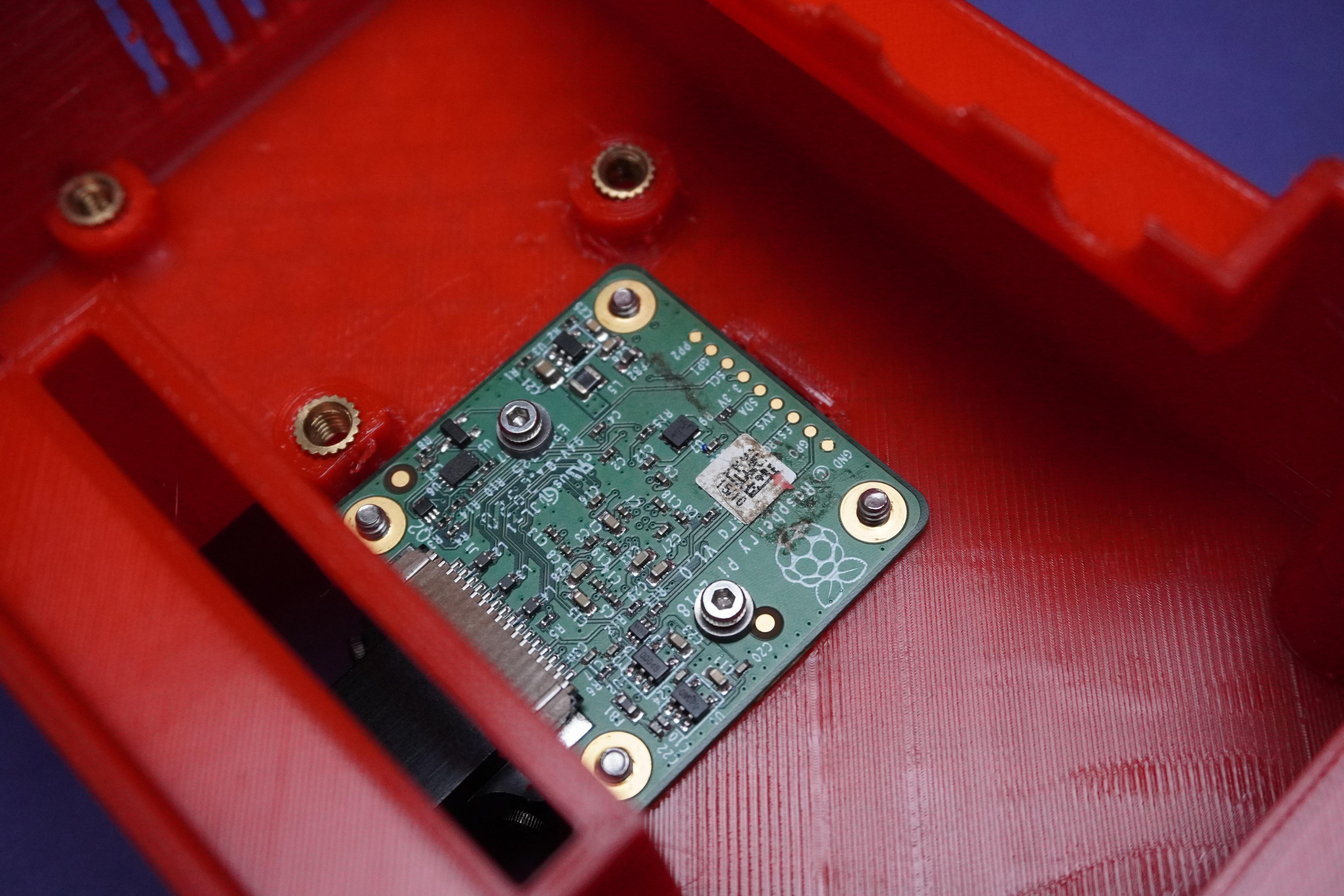
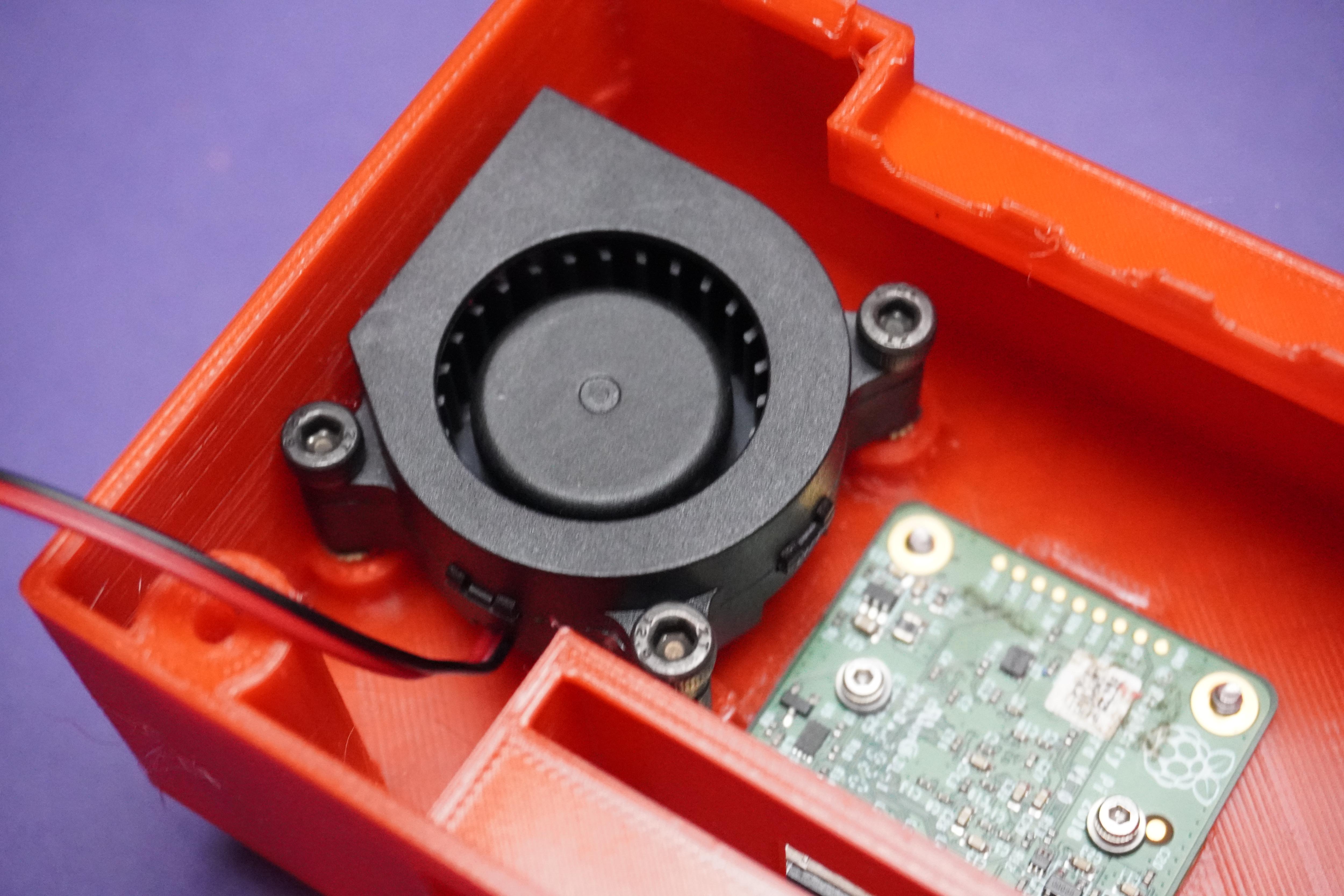
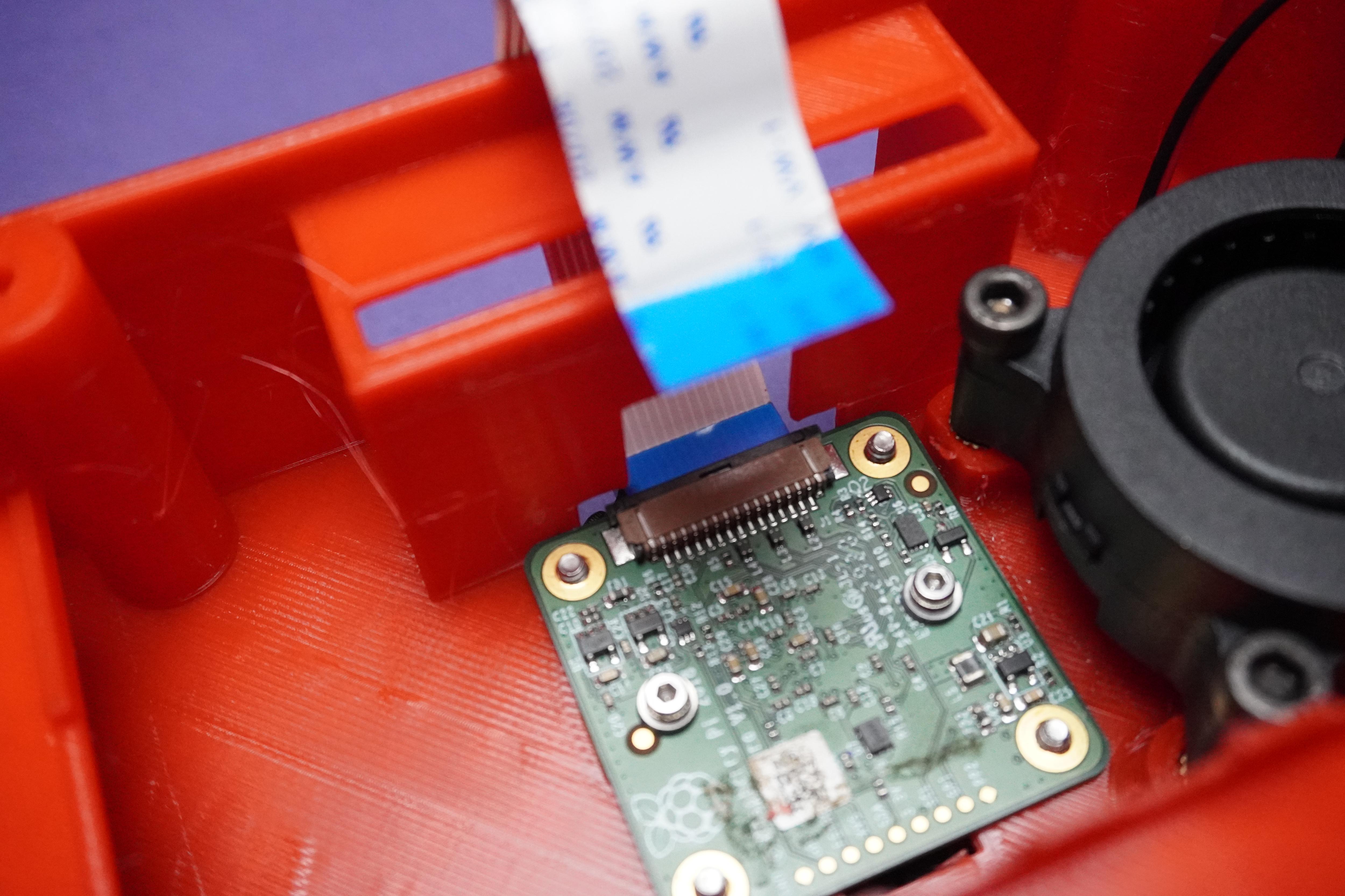
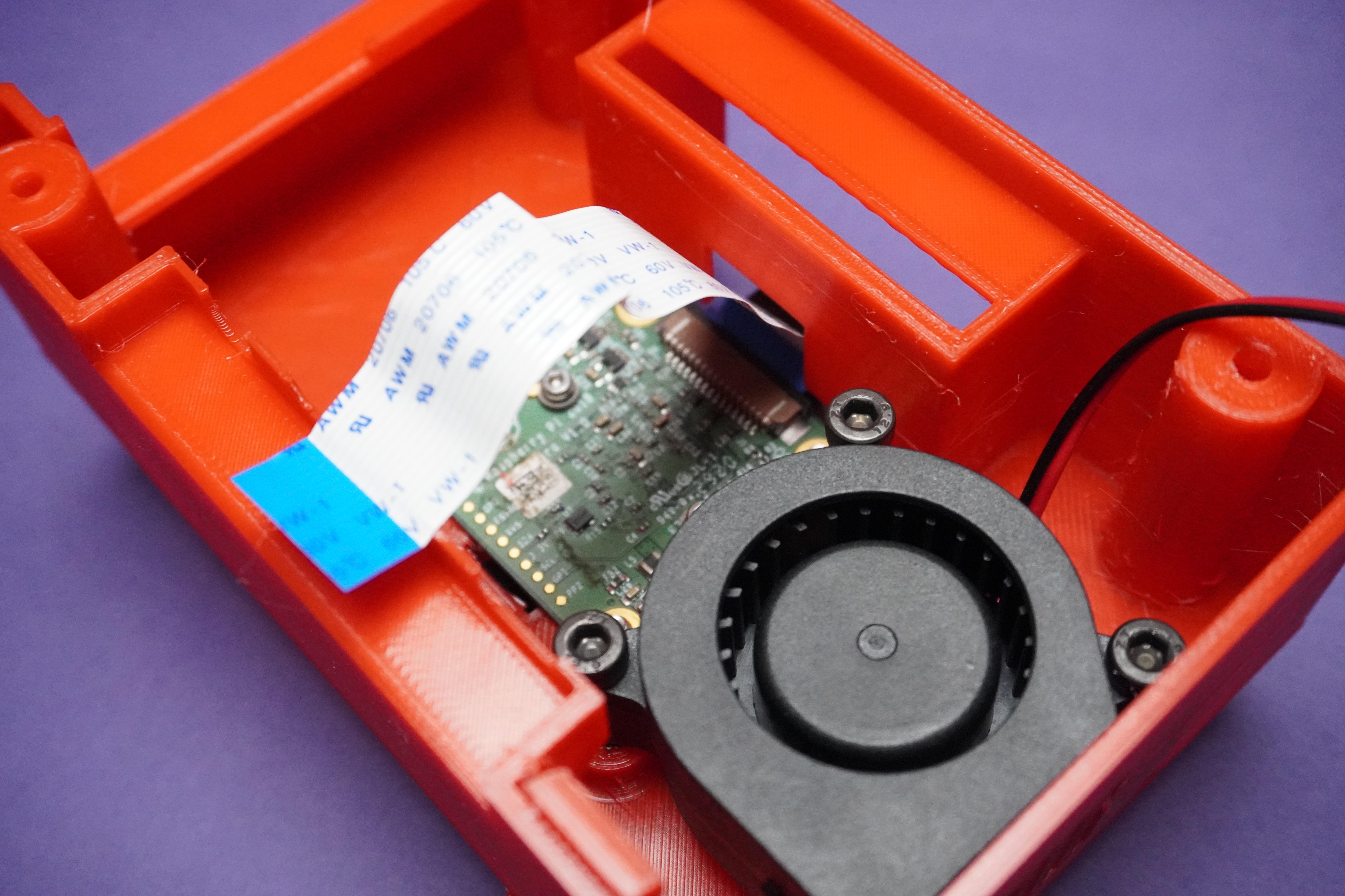
- Fix the Camera module and fan in their places using M2.5 screws and M3 screws.
- Connect the camera cable from outside and tuck it inside.
Circuit Connections
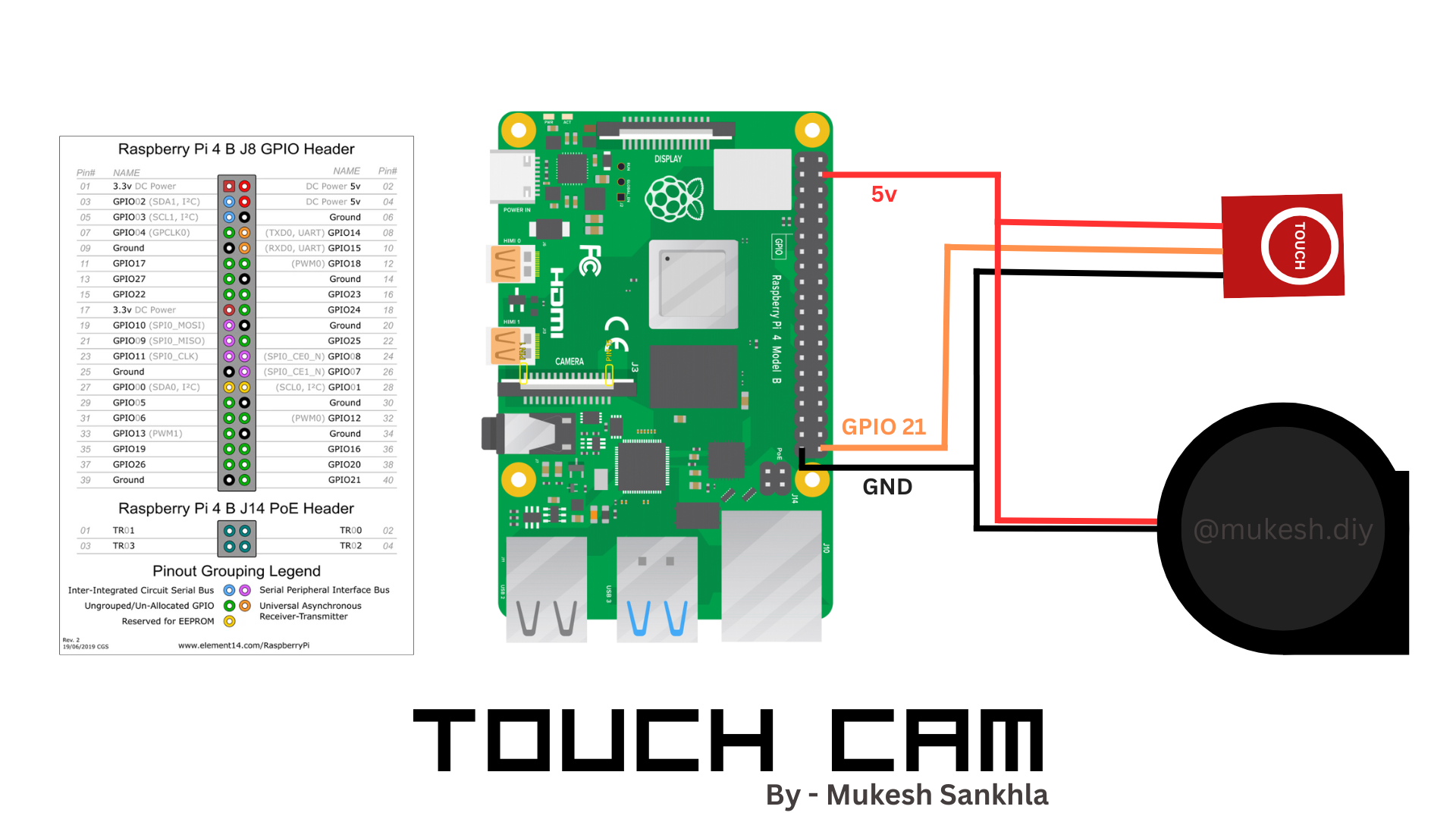
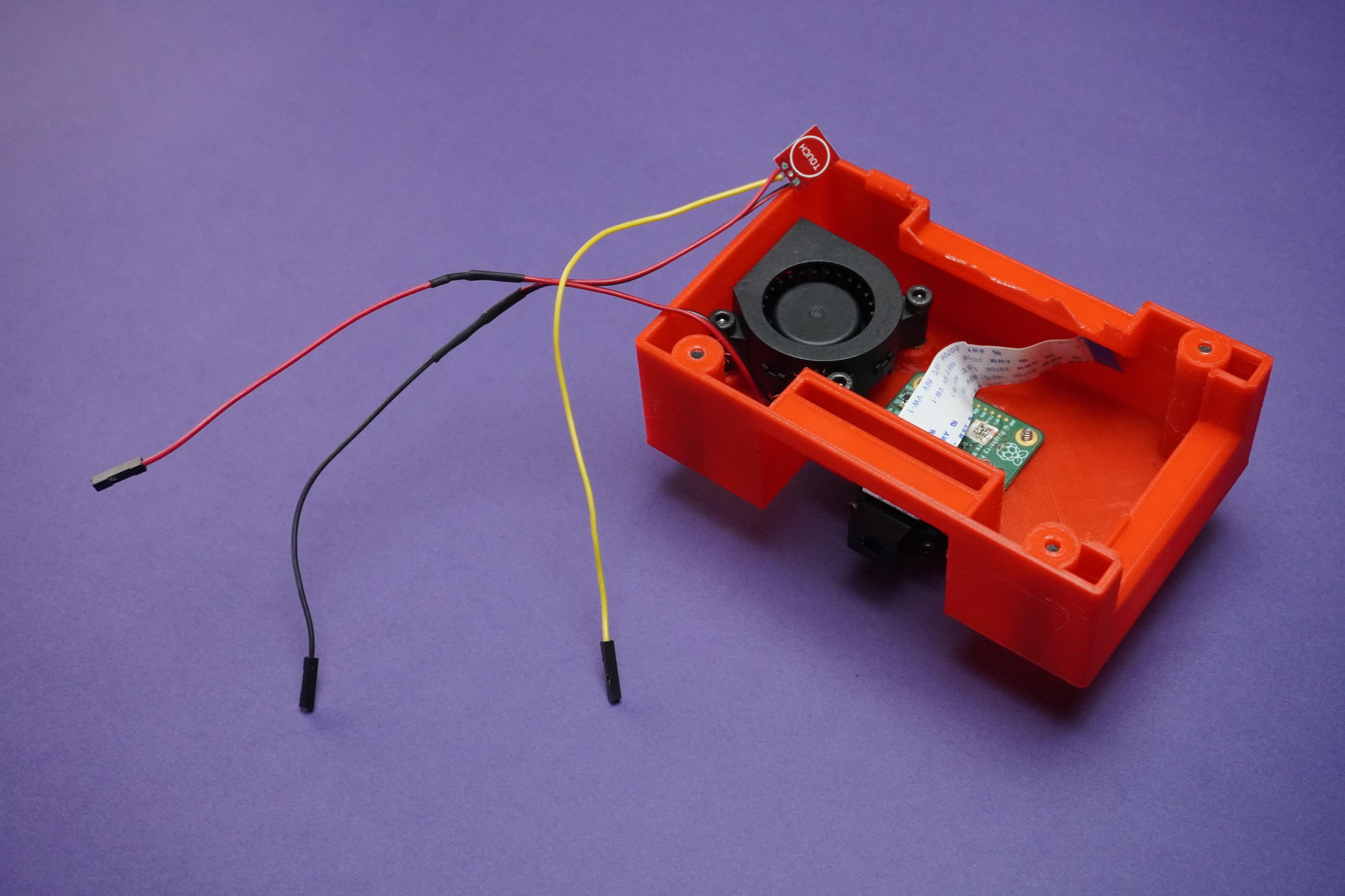
- Make the connections as shown for touch sensor input and powering the fan.
Assembly Part-3
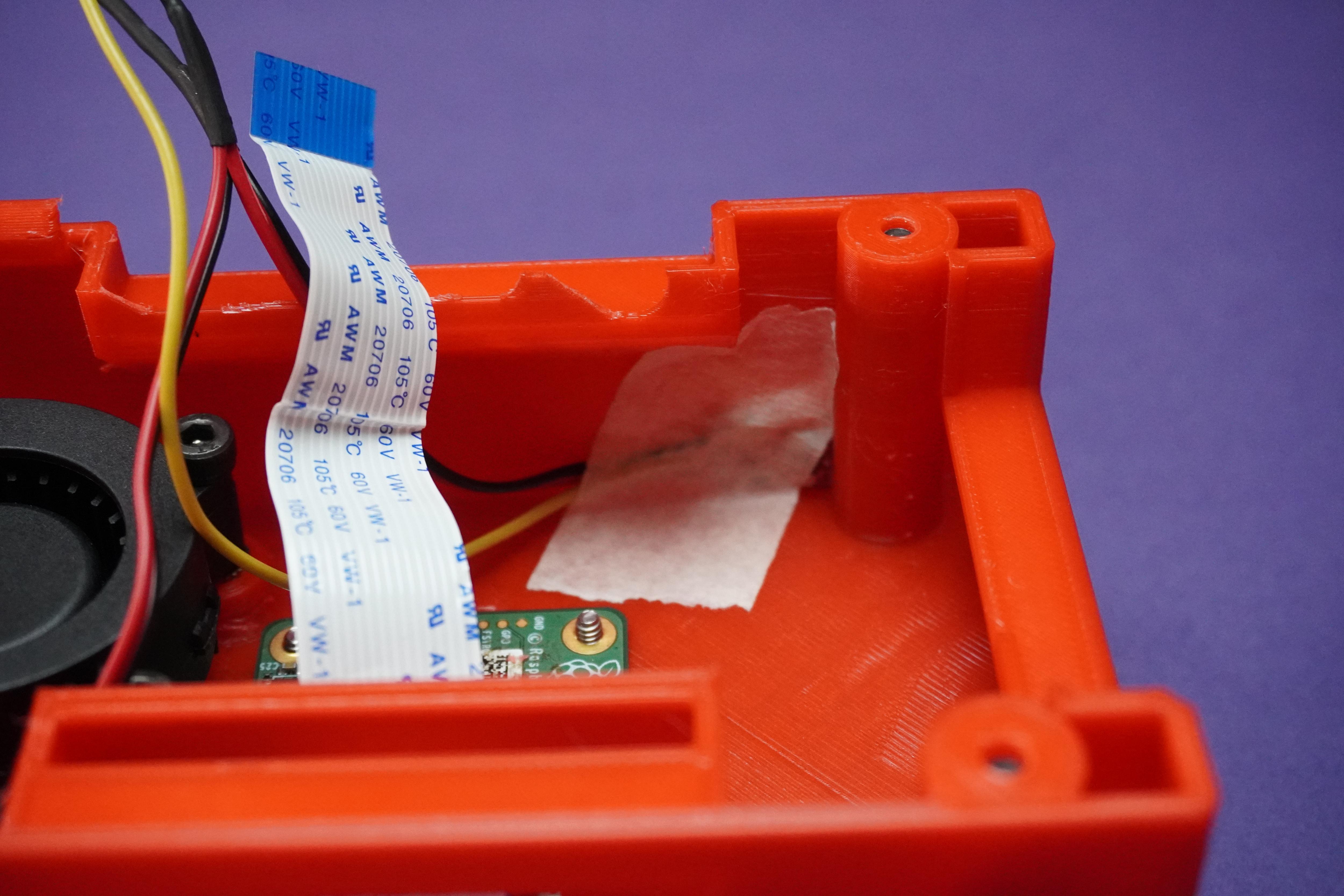
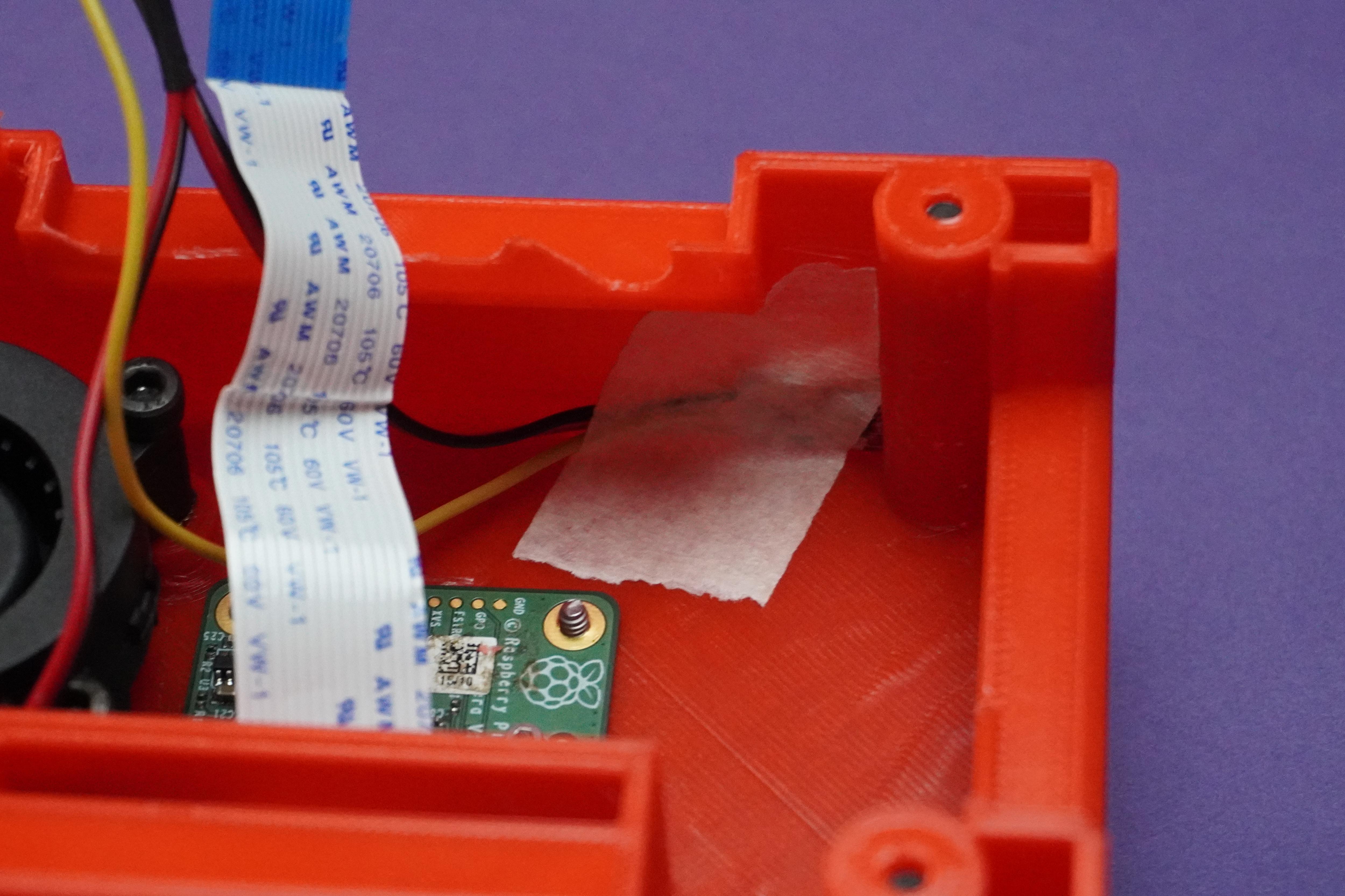
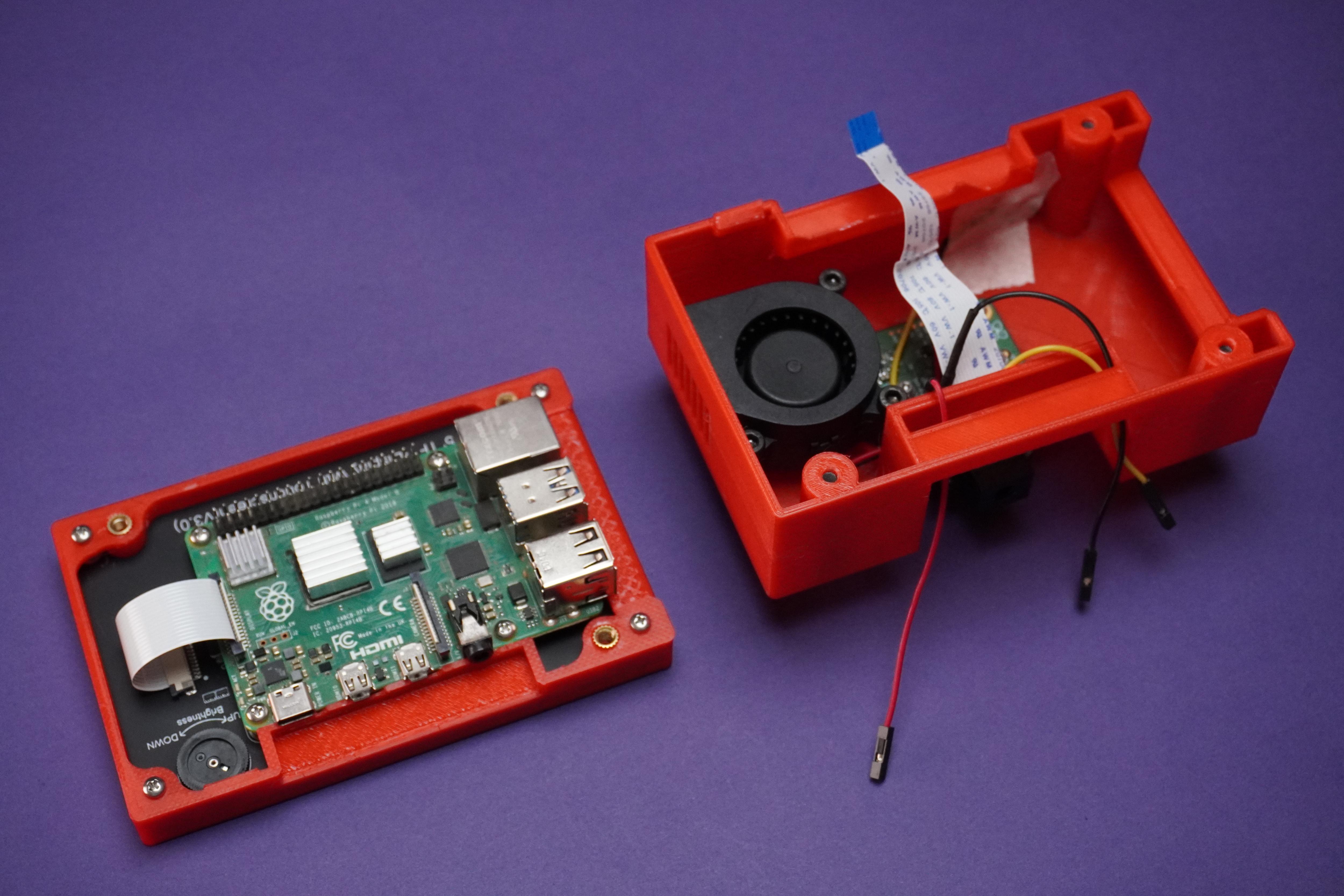
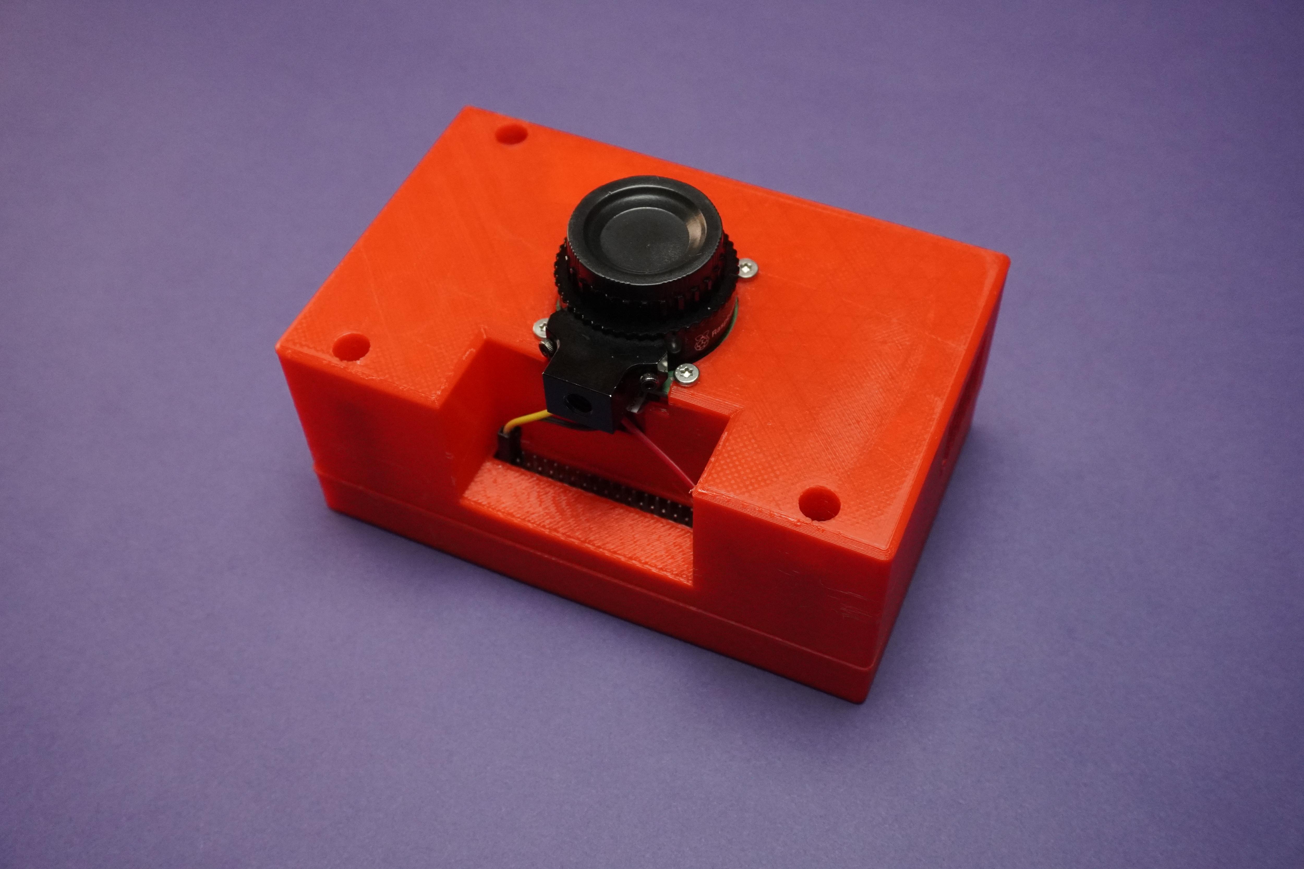
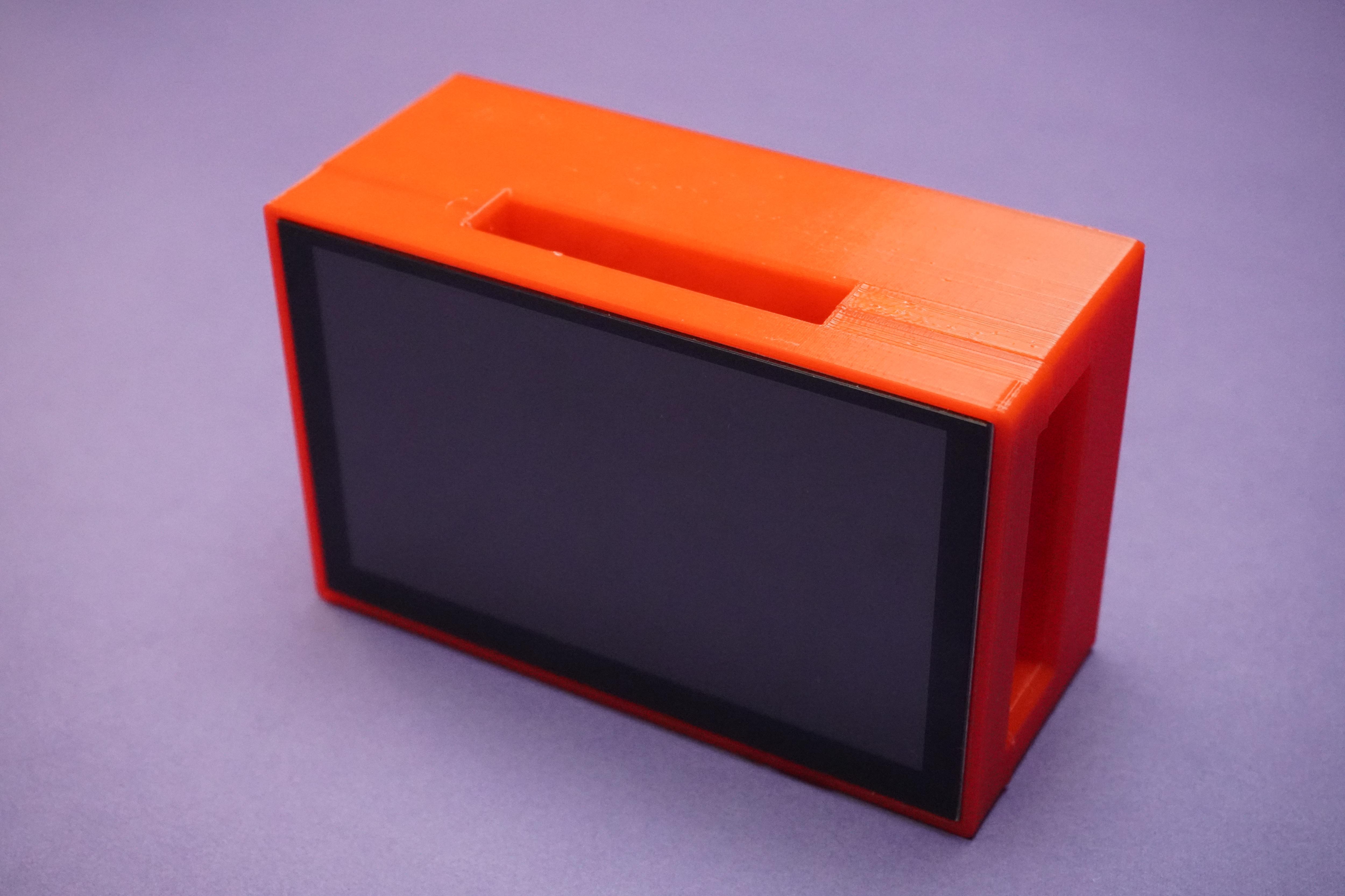
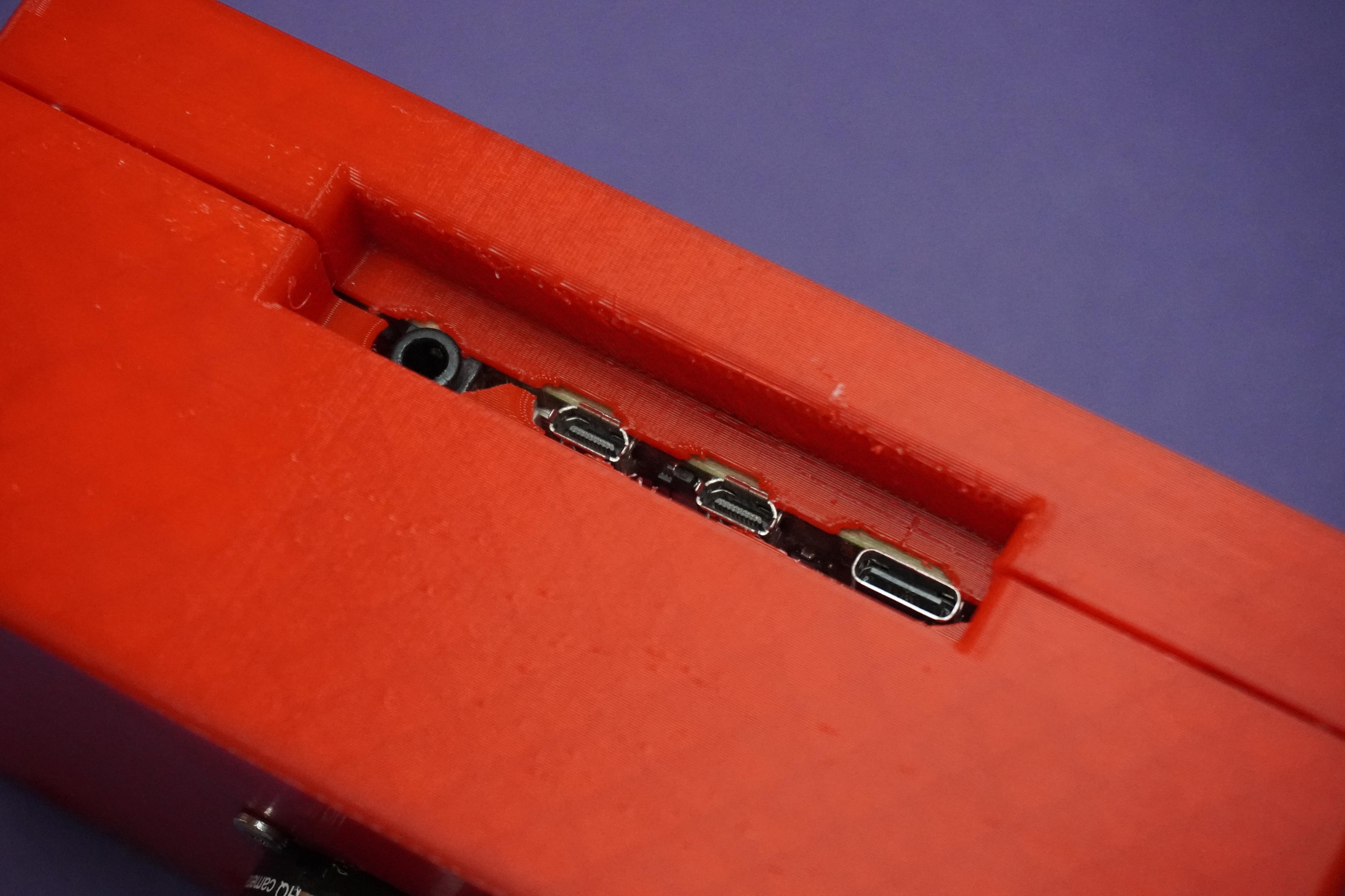
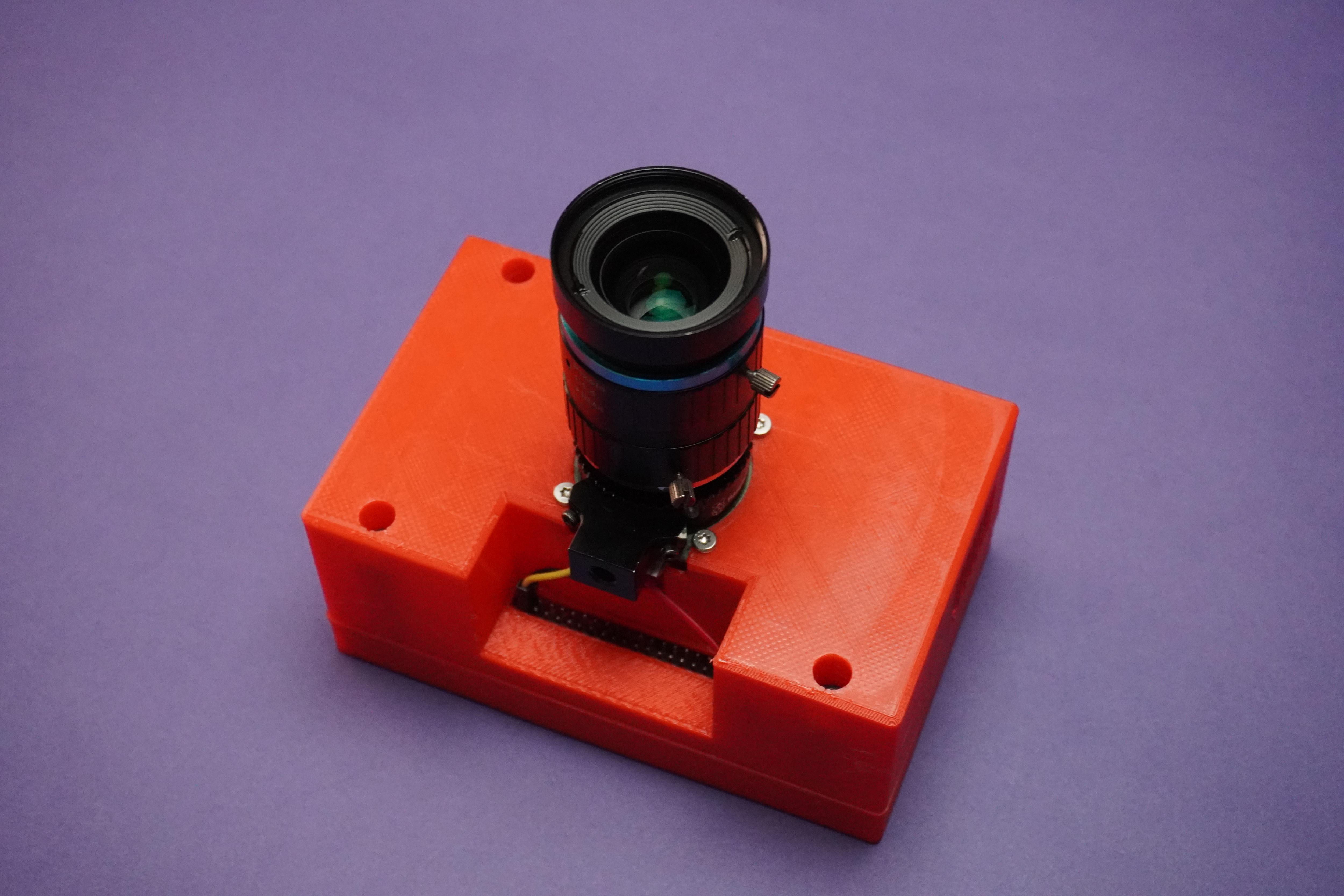
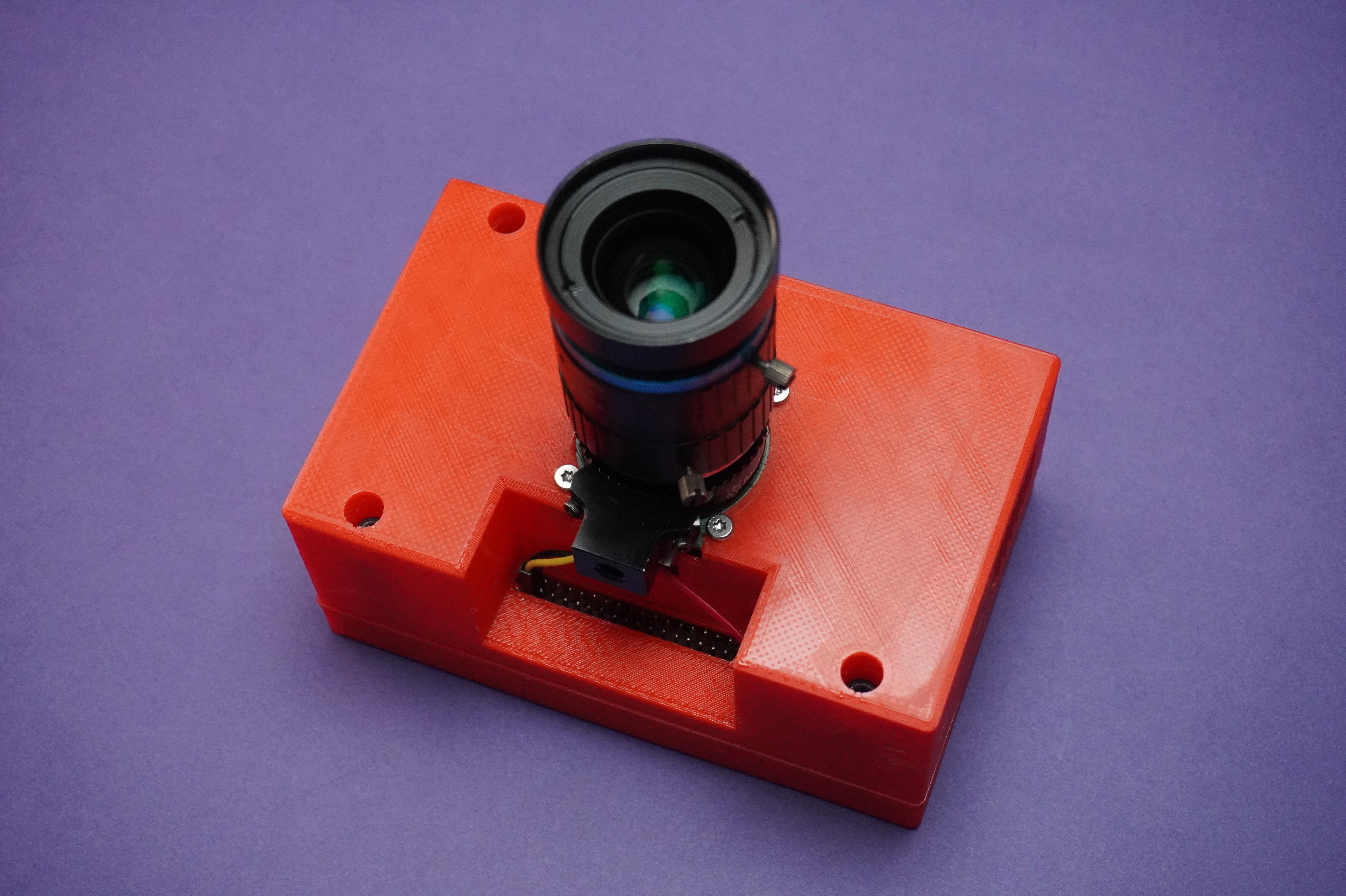
- I have used no masking tape to put the sensor.
- Now assemble everything together using M3 screws and connect the wires.
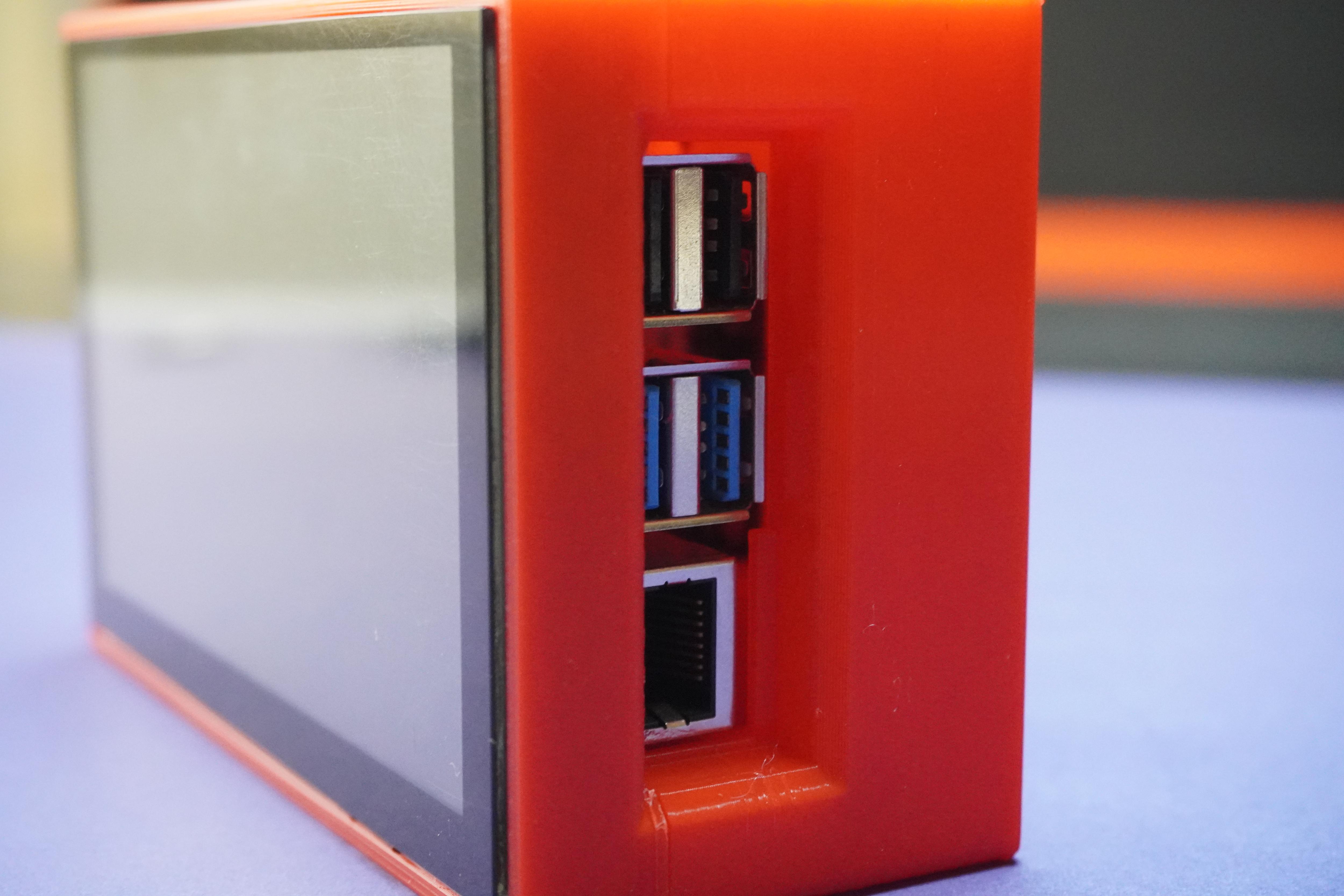
- There is a error of 2mm in the design because of which I have to adjust the Ports opening by trimming the plastic. But don't worry for you I have fixed this error in My stl files download from step19.
Software Setup
- Copy the below code into Raspberry Pi and save it as Any_File_Name.py
- Open the code in Geany and run it.
- If you get any error it might be because of picamera python package not installed, to solve this put the following command in terminal.
pip install picamera
- Now you can run the code successfully.
- The functionality of this code is when we run it will start camera preview and when we touch the sensor it will capture the photo and save it to the same directory as the python code.
import RPi.GPIO as GPIO
import time
from picamera import PiCamera


# Set the GPIO mode to BCM
GPIO.setmode(GPIO.BCM)


# Set up GPIO pin 21 as input
GPIO.setup(21, GPIO.IN)


# Create an instance of the PiCamera
camera = PiCamera()


def capture_picture():
    # Get the current timestamp for the picture filename
    timestamp = time.strftime("%Y%m%d%H%M%S")
    image_filename = f"picture_{timestamp}.jpg"

    # Capture the picture
    camera.capture(image_filename)
    print(f"Picture captured: {image_filename}")


try:
    # Start the camera preview
    camera.start_preview()


    while True:
        # Check if GPIO pin 21 is high
        if GPIO.input(21) == GPIO.HIGH:
            # Call the capture_picture function
            capture_picture()


        # Add a small delay to avoid excessive checking
        time.sleep(0.1)


except KeyboardInterrupt:
    # Stop the camera preview
    camera.stop_preview()


    # Clean up GPIO on program exit
    GPIO.cleanup()
- I would personally recommend you to use the software from My Previous Pi Cam - a Remote Raspberry Pi Desktop/Camera/Server
- Follow the instructions from Step 8 of the Pi Cam to set the remote.it platform on raspberry pi for remote access.
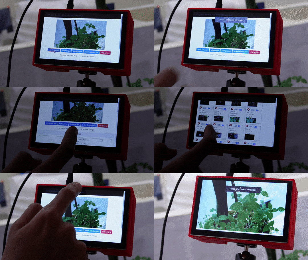
- With this software setup you would be able to access your Raspberry Pi and its camera remotely from any desktop and handhelds, you can also access the camera interface directly from bowser and photos, videos, timelapse directly to your device this makes everything easy and hassle-free, no codes and no further commands.
- Just after setting up the software bookmark localhost:80 into your Raspberry Pi's Browser and run the browser in full screen mode by clicking the 3dots on right hand side corner.
Conclusion


I hope you found this tutorial help full, if so please let me know below in the comments. If you have any questions or suggestion please feel free to drop down below and also if you made Touch Cam for your self just showcase in the below I Made It! section.
Thank You!
See you with another project ;)