Touch Board + Ableton Live
by Bare Conductive in Circuits > Audio
3163 Views, 14 Favorites, 0 Comments
Touch Board + Ableton Live
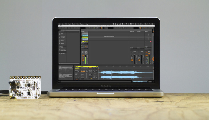
Ableton Live user? Cool! The Touch Board works great with Live. The following tutorial shows you how to get your board set up and gives you a brief introduction to our basic Live project.
For more project ideas visit www.bareconductive.com
Materials
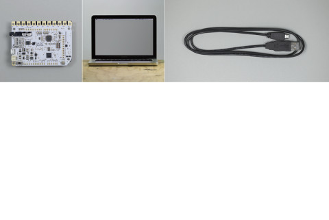
To begin you will need:
1 x Touch Board
—
1 x USB A to Micro B cable
1 x Computer running Ableton Live 9.0 or later
—
1 x Internet connection (but you are reading this, so I guess you must have one!)
Upload the MIDI Controller Code to Your Touch Board
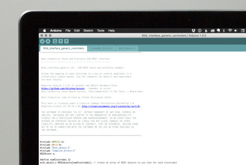
Your Touch Board will need our Touch and Proximity USB MIDI interface code to communicate with the Live project. A link to the code is below. Before hitting upload make sure to select “Bare Conductive Touch Board (USB MIDI, iPad compatible)” under Tools/Board.
If you haven’t set up the Arduino IDE to work with your Touch Board yet, make sure to complete our “Setting up Arduino with your Touch Board” tutorial first (link below).
Download the Live Project
To download our Generic MIDI Controller Ableton Live project, click the link below and unzip it to a convenient location. Our project runs on Live 9.0 or later. If you don’t already have Live installed you can find a link below.
Start It Up
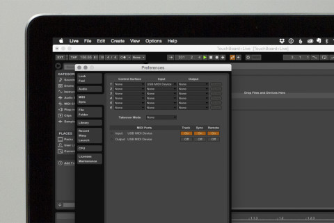
Make sure that the Arduino programming environment is closed. Plug in your Touch Board and open up the Live project. Navigate to Live/Preferences/MIDI Sync. You should see yout Touch Board under Input as “USB MIDI Device.” Lower in the dialogue box, in the MIDI Ports section make sure to turn sync and remote on.
Exit the Live preferences and take a look at upper right hand of your project. You should see a blinking light every time you touch one of the electrodes on the Touch Board. You will probably also have noticed that your project is now making noise! If so, move onto the next section.
MIDI Mapping
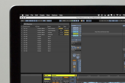
*Before you move to this step, we would suggest unplugging anything connected to the electrodes on your Touch Board – Electric Paint, crocodile clips, tea kettles, whatever – unplug! The reason for this is that the Touch Board creates very sensitive sensors and even getting near them can create a signal which makes the re-mapping process a huge pain. So unplug/unclip/unstick everything before moving onto the section below.
Our Generic MIDI controller Arduino code and Live project are intended to give you a basic idea of whats possible when you combine a Touch Board with this powerful piece of software, so we’ve kept the mapping simple. Each one of the Touch Board’s electrodes is mapped to a different function in the project. You can identify this mapping by clicking the “MIDI” box in the upper right hand corner.
You’ll notice that some of the blue boxes have alphanumeric symbols on top of them that correspond to the list on the left. This is the mapping that defines what the Touch Board’s electrodes are assigned to within Live. You’ll notice that there are a range of options available to change range and mapping.
If you want to re-map one of the electrodes simply click on what you want to map in the Live interface (when the MIDI button on the upper right corner is selected) and then touch the electrode that you want to assign it to. You should see the alphanumeric code change. Click the MIDI button on the upper right again to finish the mapping process.
Want more info about MIDI mapping in Live? Check out the link below for an awesome tutorial by Ableton about how this all works.
Experiment! Changing the Range and Sensitivity of Your Sensors
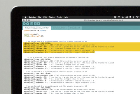
Want to get more out of this basic project? Cool. First step is to take a look at the Arduino code that you uploaded in step one. Each electrode has a range of adjustments available. Best place to start is to adjust the “inputMin” and “inputMax.” We would suggest leaving the other variables alone initially as that way Live is more likely to get information it can work with.
Now that you have a Touch Board connected to Live you’ve got a great platform for making some amazing projects. Have fun and let us know how you get on!
If you liked this tutorial visit www.bareconductive.com for more!