Topology Optimisation for Beginners (Custom Monitor Stand)
by tin-foil-hat in Workshop > 3D Printing
4612 Views, 41 Favorites, 0 Comments
Topology Optimisation for Beginners (Custom Monitor Stand)
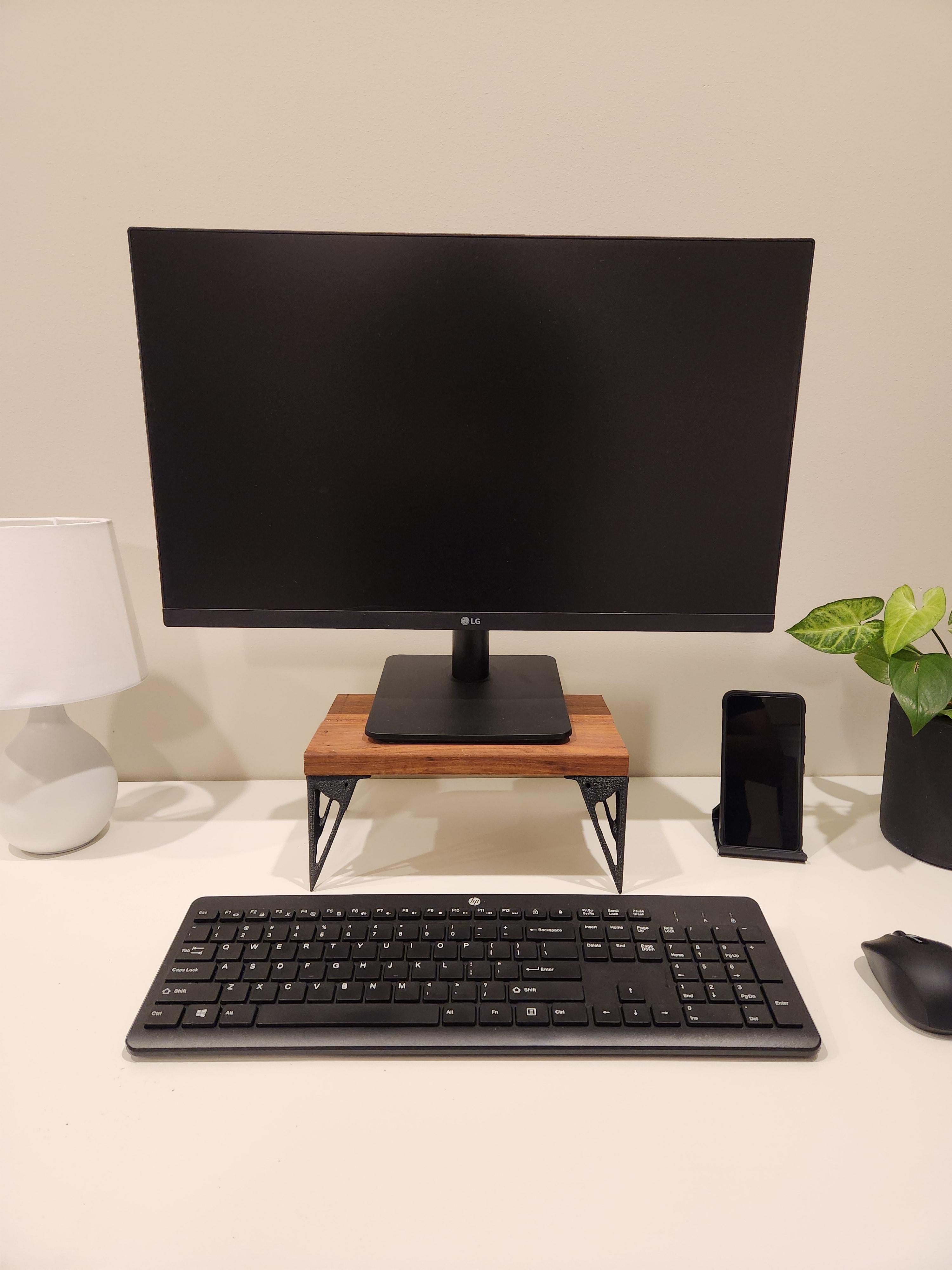
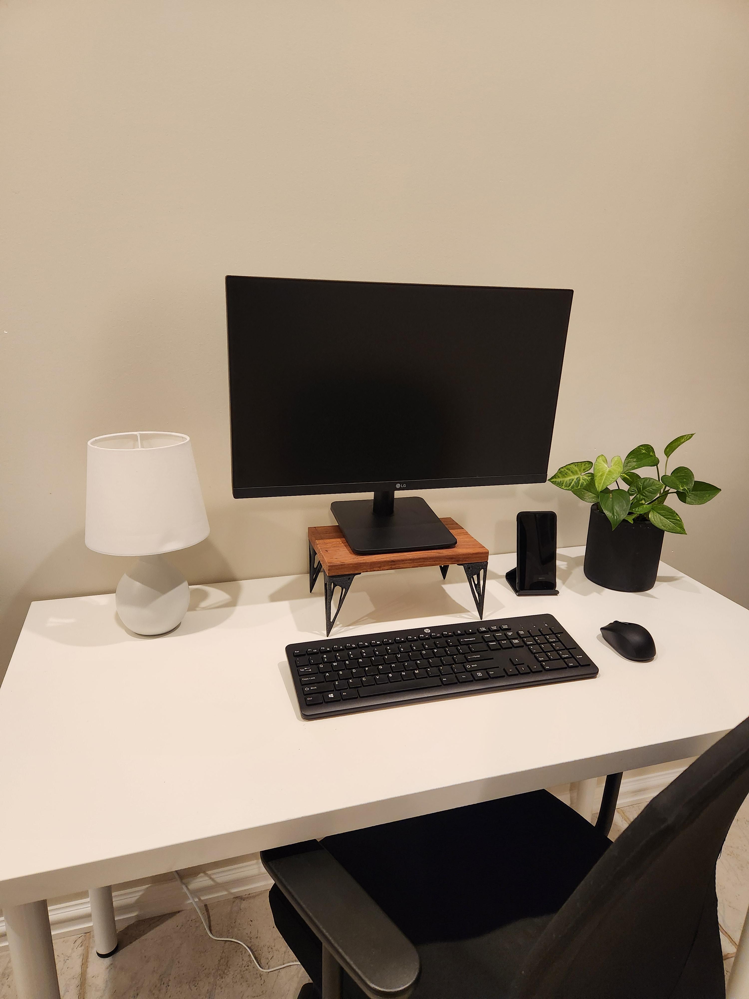
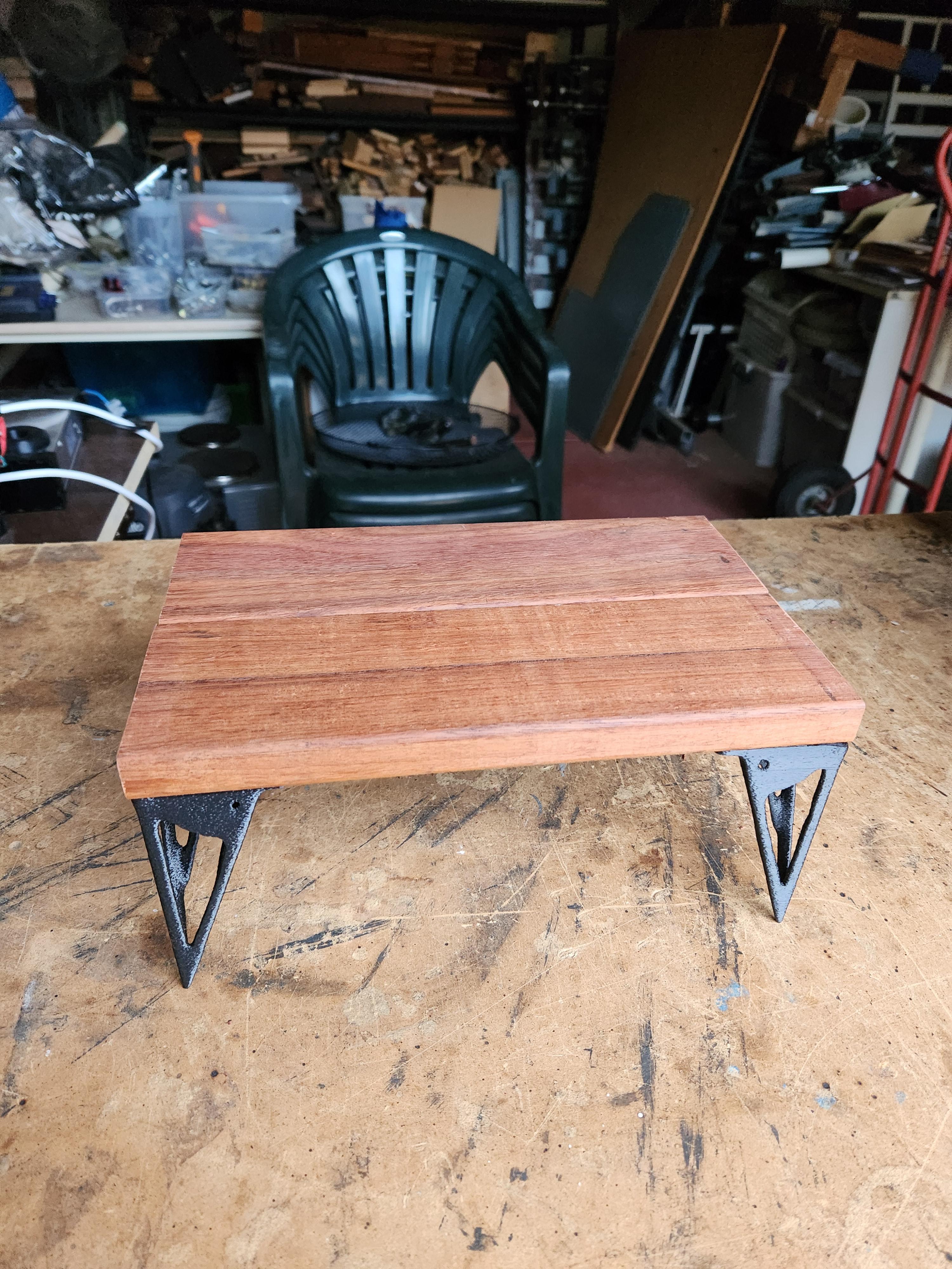
Having your monitor at the correct height can lead to a huge benefit in workflow and is an easy fix to your posture. So what better way to raise your monitor's screen than designing and 3D printing a futuristic-looking monitor stand? This is a quick tutorial on how to use Fusion360 to generate topology-optimised parts for 3D printing!
I am an Australian high school student who has a passion for engineering, woodwork and electronics. I hope this tutorial can help teach you the basics of topology optimisation and get you thinking about how the simulations tab in Fusion360 alongside AI and other complex algorithms can assist you in your designs.
Supplies
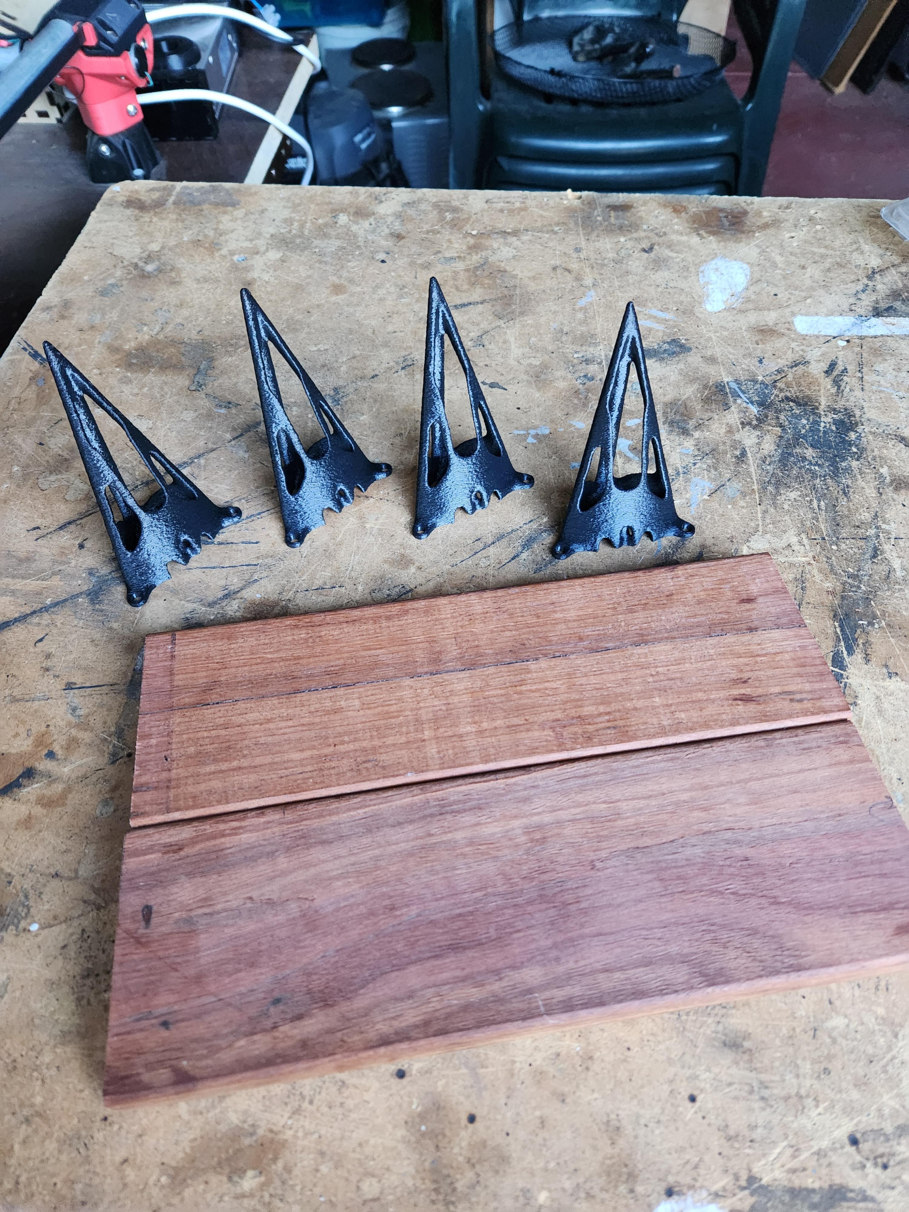
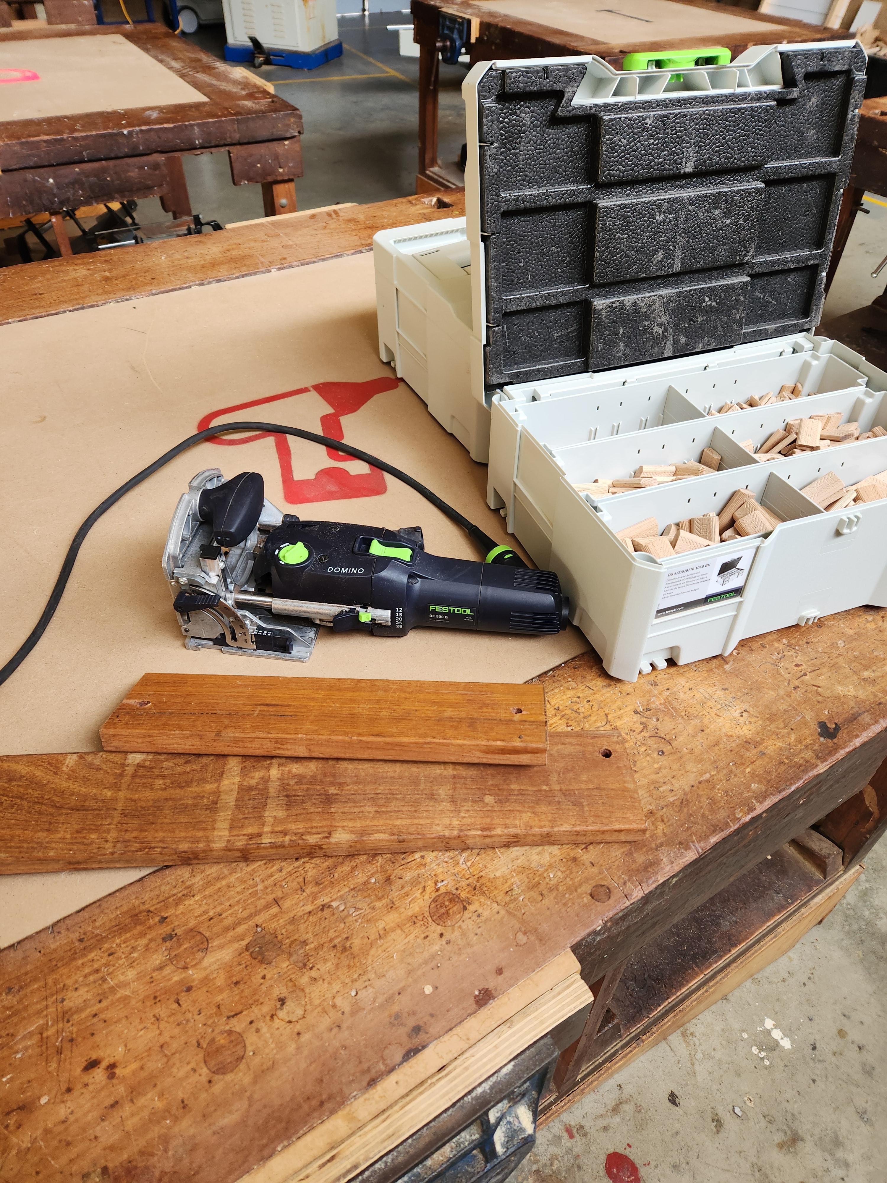
Materials:
- 3D printing filament (I used PLA)
- 8 Small Screws (To secure the legs to the top plate)
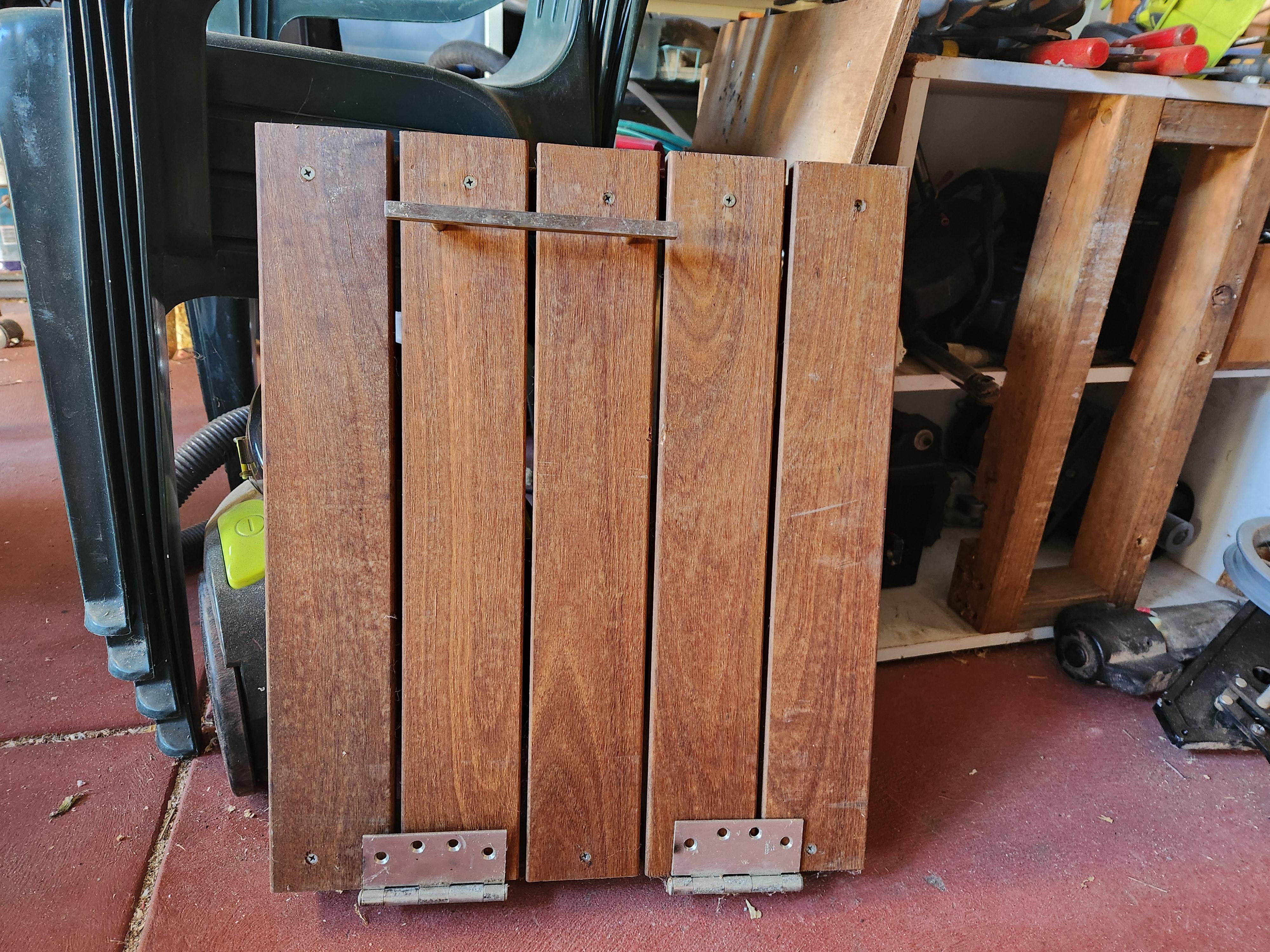
- Planks of wood (Enough to build the size of top you need) - I used two 85x270x19mm salvaged planks
- Wood Glue
Tools:
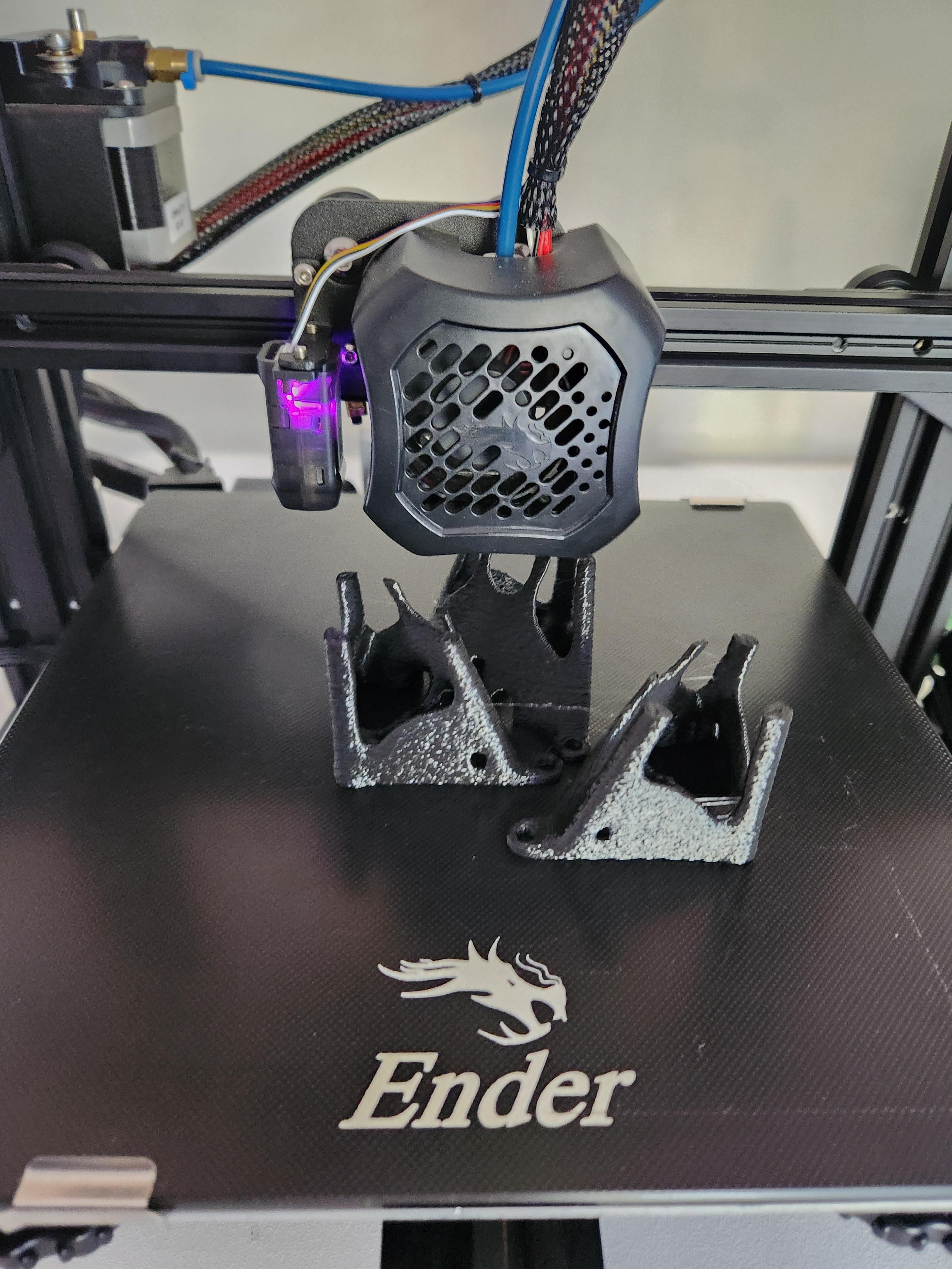
- 3D printer
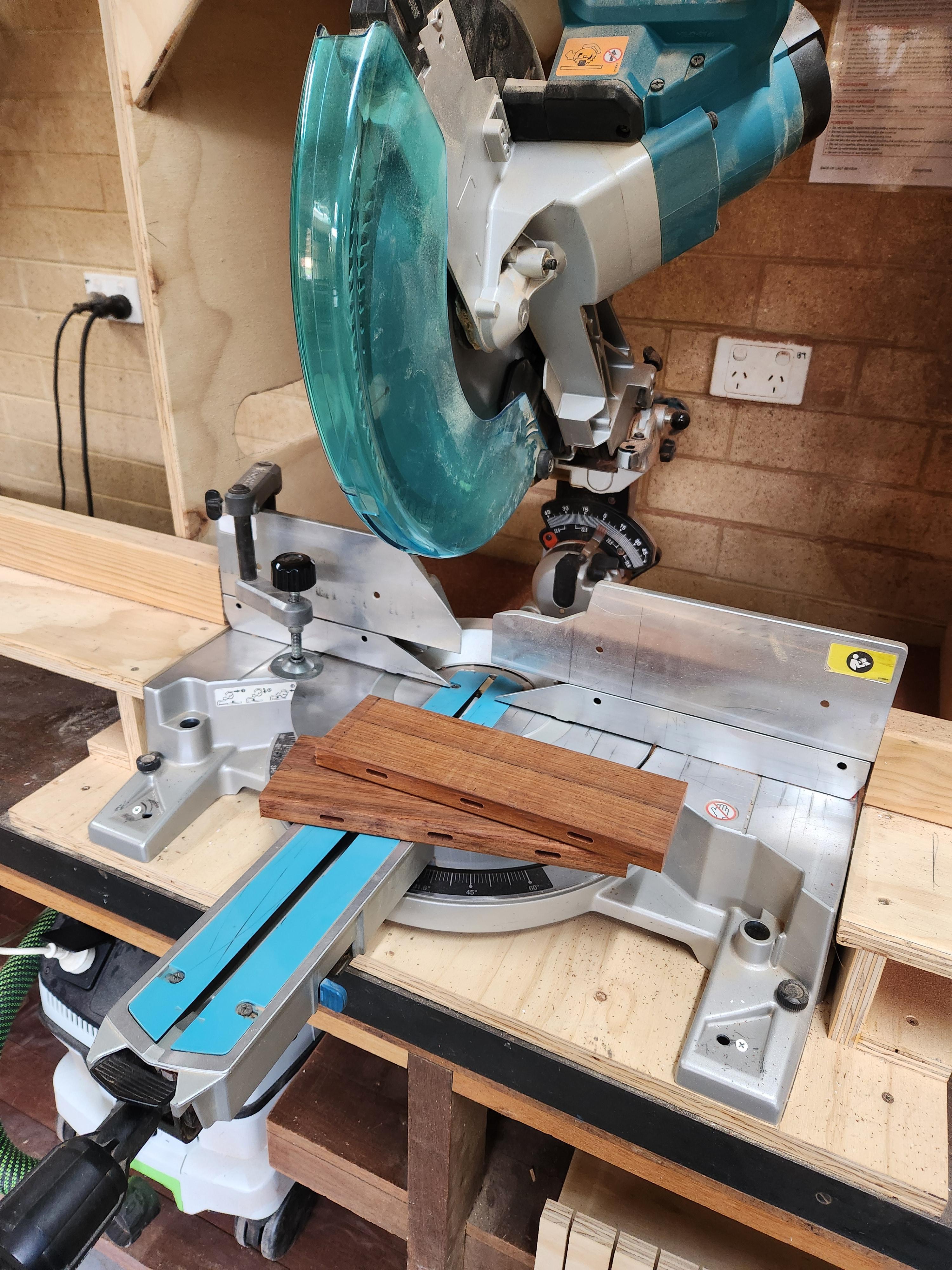
- Wood saw, Drop Saw or similar machine to cut wood planks to length
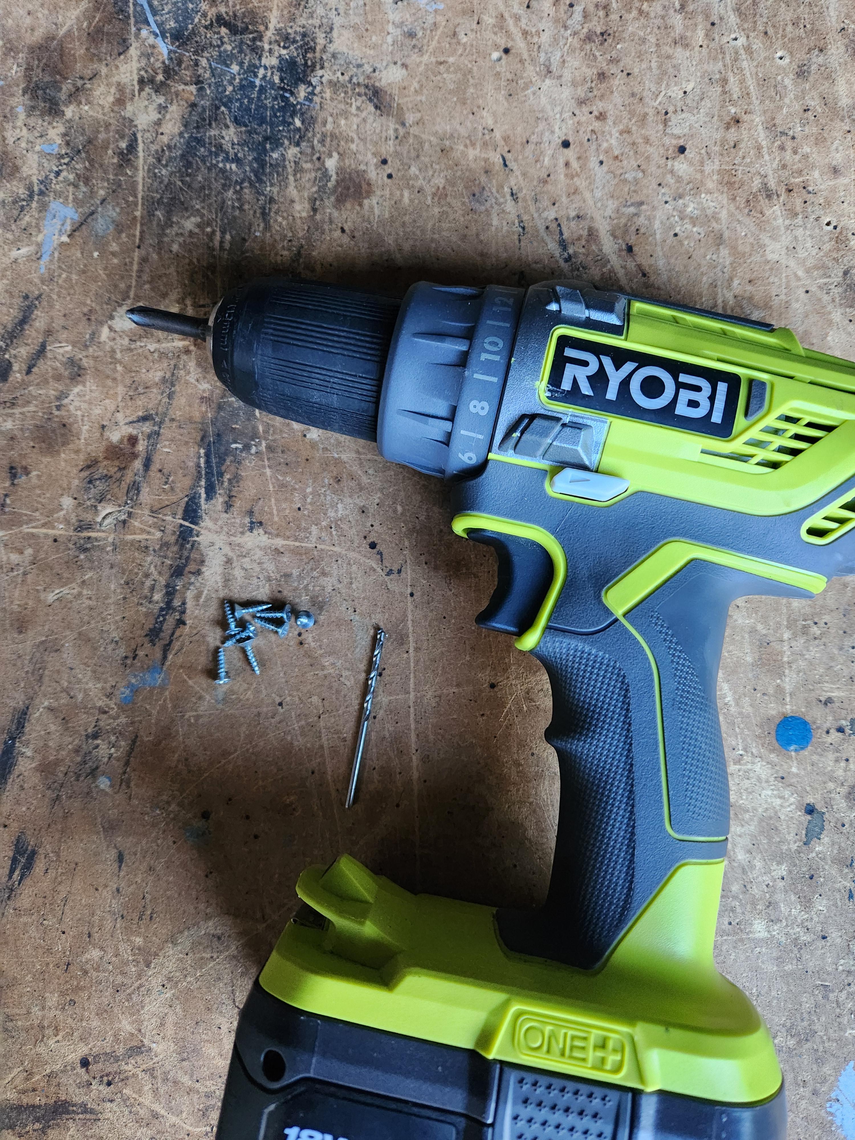
- Drill + Drillbit to suit screws
- Screwdriver (That matches the screw heads)
- Domino/Biscuit Jointer (An alternative method is mentioned in step 9)
What Is Topology Optimisation?

Topology optimization is a computational method used in engineering to design and refine structures, aiming to achieve the most efficient use of material while meeting strength requirements. Through iterative algorithms, it removes material to reduce weight. By eliminating unnecessary material and optimizing the layout, topology optimization can significantly reduce the material usage of 3D-printed parts making them cheaper. In our case, it means we can keep a strong structure, whilst removing most of the unnecessary weight.
Image from 3Dprint.com
Finding the Correct Height

To ensure optimal monitor height, aim to position the top of the screen 5 to 10cm (1 to 3 inches) above eye level. Experiment with different heights using books or similar objects under the stand until you find the most comfortable setup for you.
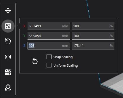
I needed the top of the screen to be 54cm above the table. After measuring the monitor's height and the thickness of the planks for the stand, I calculated that the legs should be around 106mm tall.
Making the Solid Model
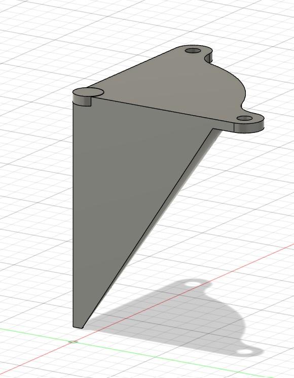
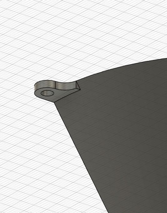
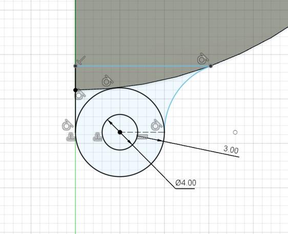
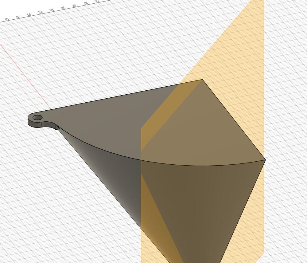
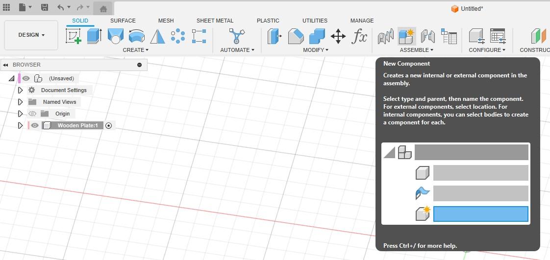
The first step is to design a solid model. Once you've opened Fusion360, create a new component by clicking the New Component button under Assemble.

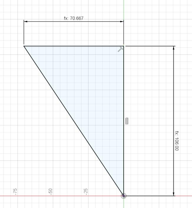
Now it is time to draw the main sketch. You could draw any shape you like for this step so long as it has the correct overall height (or close to - as we will scale it later). I chose a simple right-angle triangle with a height of 106mm and a width of 106*2/3.

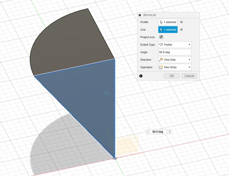
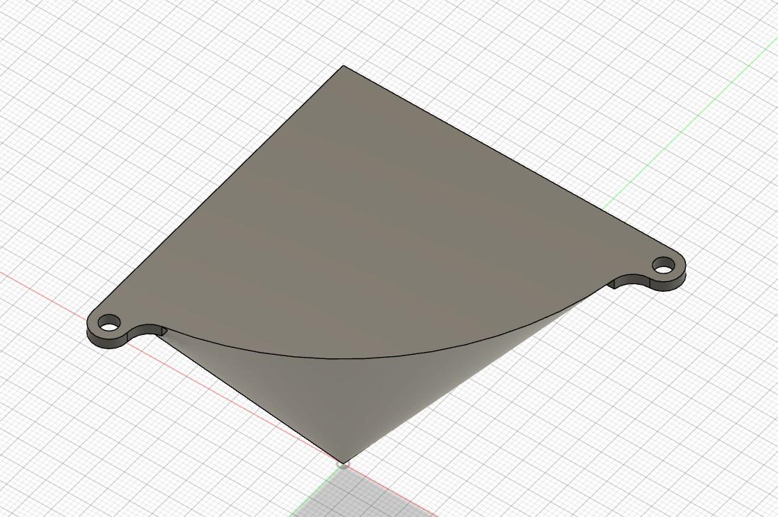
Then use the Create > Revolve feature to turn your sketch into a 3D model. Since each corner of the monitor stand needs one leg, by revolving only 90 degrees it means we get 2 flush sides, preventing the legs from sticking out the side of the wooden top.

To add mounting holes, we'll start a sketch on the top of the model. Start by drawing a tangential circle with another circle inside it on one of the corners. The inner circle represents the screw hole, while the outer one is the material around it. It's crucial to overestimate the material needed because refining the mesh later may result in some material loss, potentially causing the screw to snap the model.
Connect the concentric circles to the top face using an arch on one side and a line on the other. Since the model is cone-shaped, extruding this sketch downward alone won't connect it to the model. To fix this, join the base of the arch and the end of the line with another line. This will provide a flat face when extruded that we can then extrude again.

Then by using the Create > Extrude feature, we can join our mounting holes to the component. You need to do this in 2 separate extrudes. The first one is of the new sketch (downwards) of the desired thickness. The second is of the innermost flat face you have now generated, and extrude it into the main component, joining the 2 bodies together.

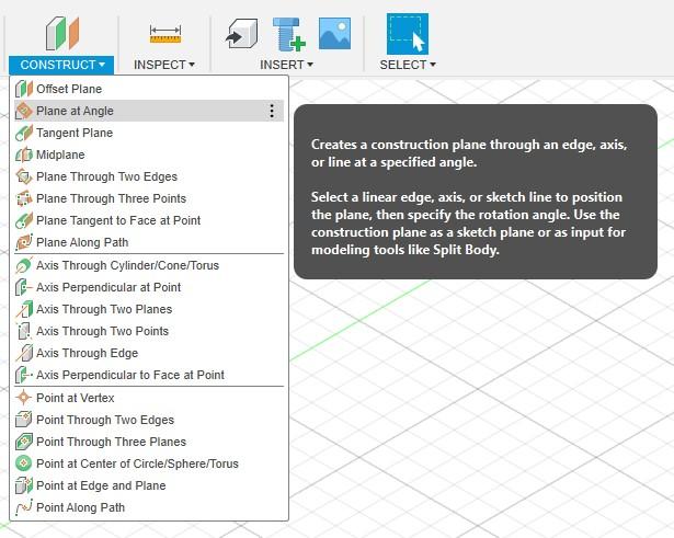
Next, create a plane at 45 degrees. You can do this by going to Construct > Plane at Angle. This plane should divide the model down the middle. We can then mirror the component using the Mirror feature about the plane, resulting in a body with 2 identical mounting holes. We only need 2 mounting holes as when attached to the top plate of the monitor stand, the weight force will try to push the legs outwards, resulting in a compression force on the corner, whilst pulling against the screws, holding it in place.


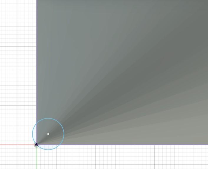
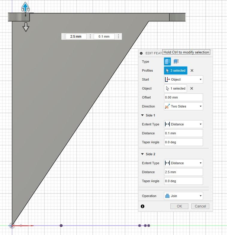
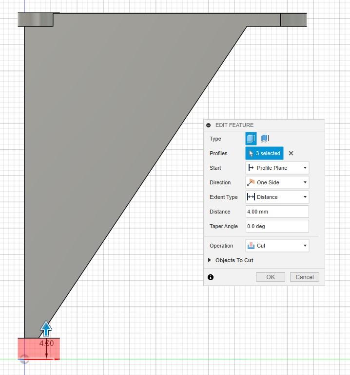
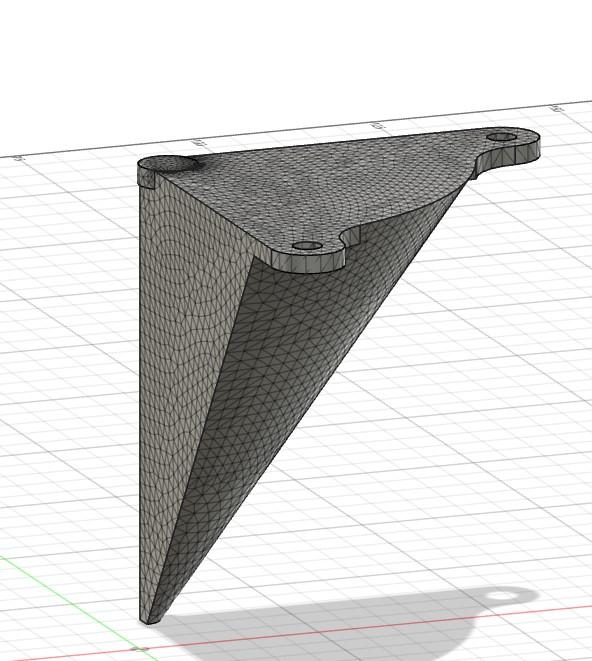
So that the final design doesn't have such a sharp point, we can create a sketch on the bottom of a circle as shown below. This allows us to cut away a section of the point, whilst also adding a section at the top for additional stability (using the extrude feature).


Topology Optimisation
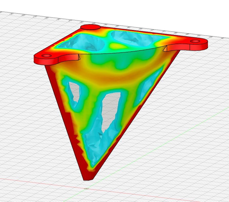
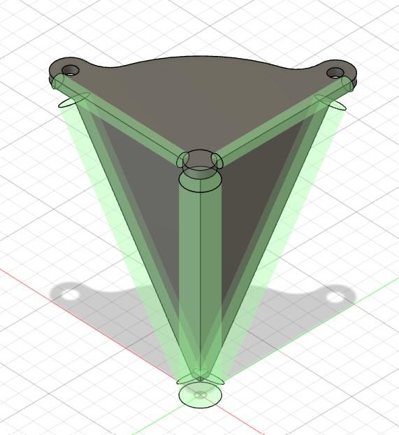
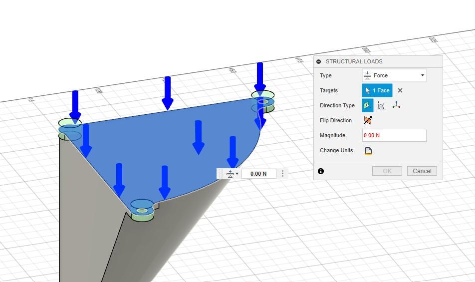
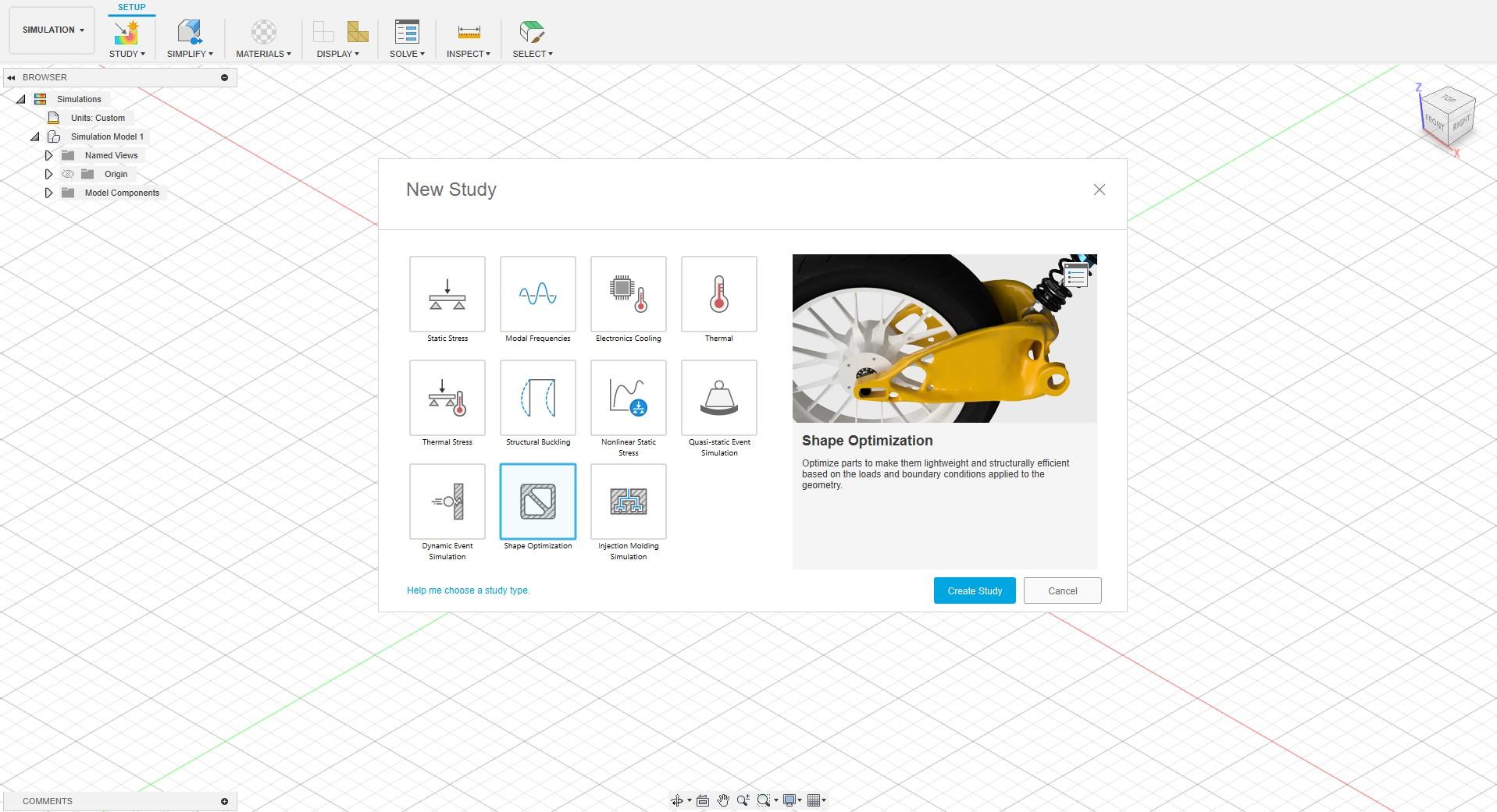
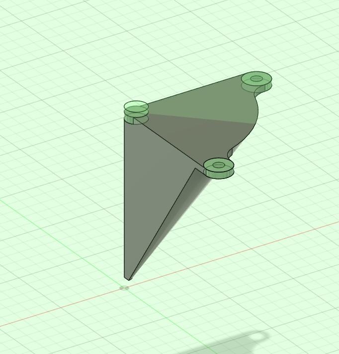
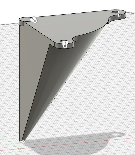
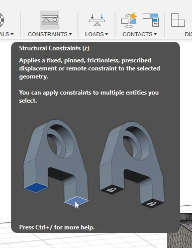
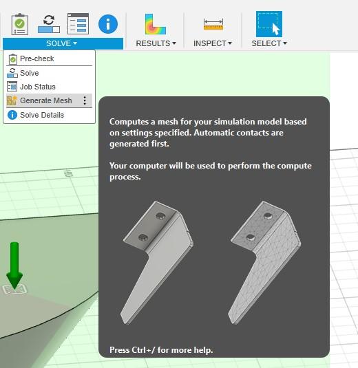

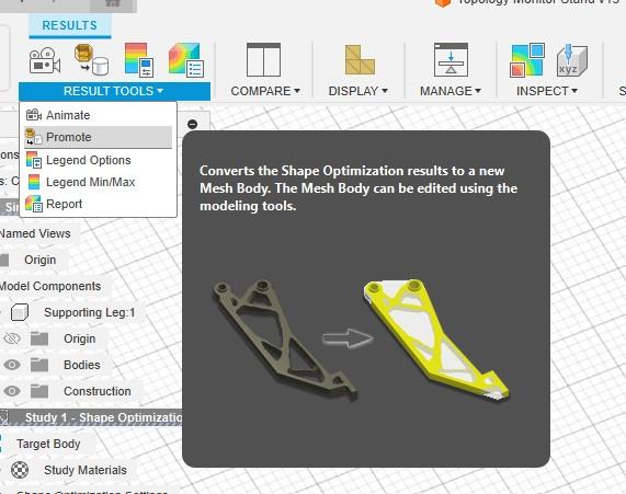
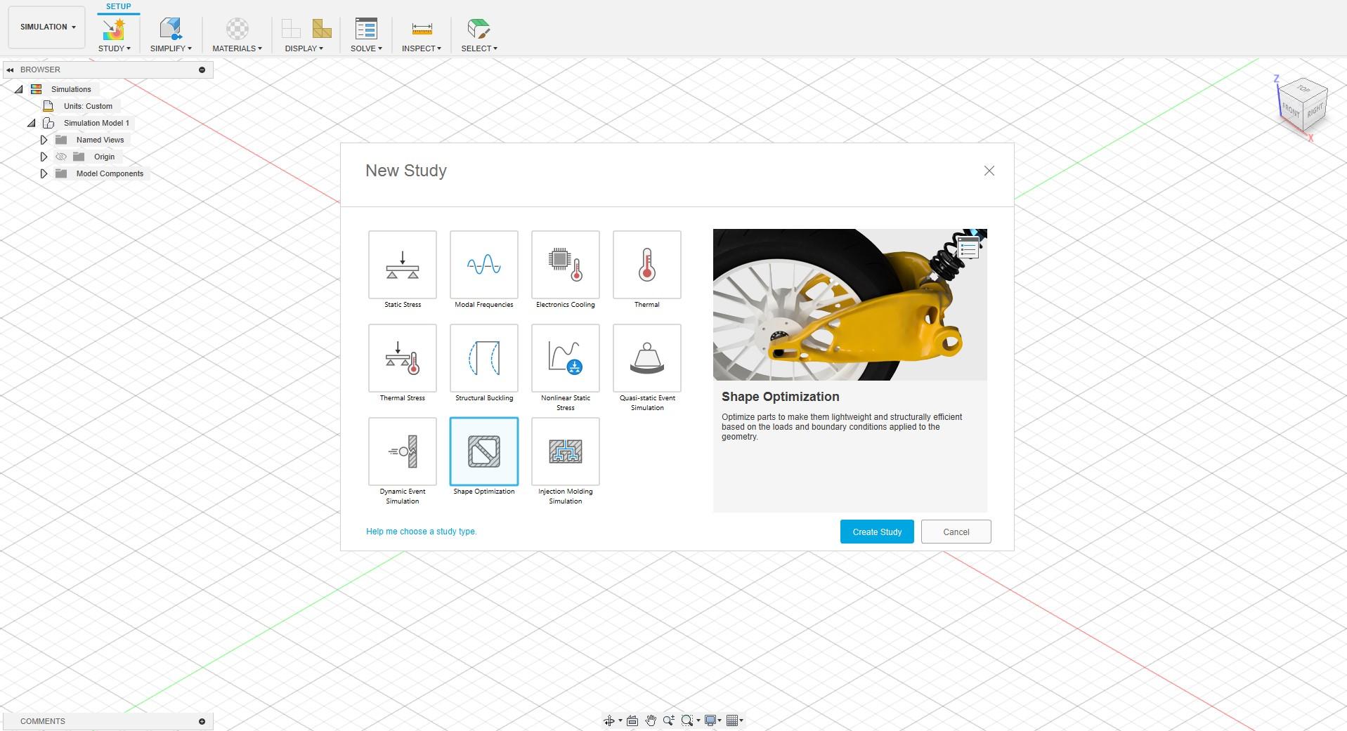
Now that we have our solid model, navigate to the Simulation tab by clicking "Design" in the top left corner. It will prompt you to start a new study, here we want to select shape optimisation. Do however note that Fusion360 has a wide range of simulation tools we can utilise in future projects (although most if not all will cost cloud credits - students can access some however for free).
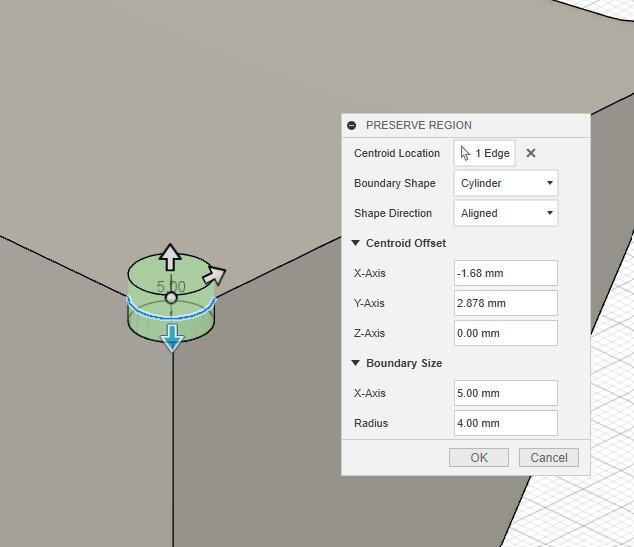
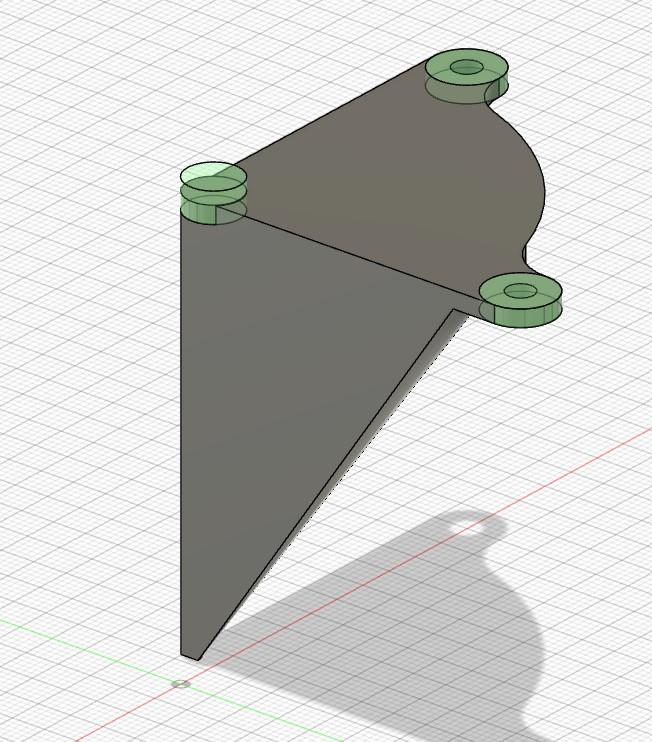
The first step is to define the regions we do not want the optimisation to change. We can do this using the preserve region feature. Select the outer contour of the region you wish to keep (in our case the 2 mounting holes and the back circular feature), then scale the region using the arrows and feature pop-up. Your model should look like the following:


We also want to preserve the outer structure and the face on the bottom (where it comes to a point). You can do this by using preserve region, and this time selecting the outer contours of the model. As shown below:

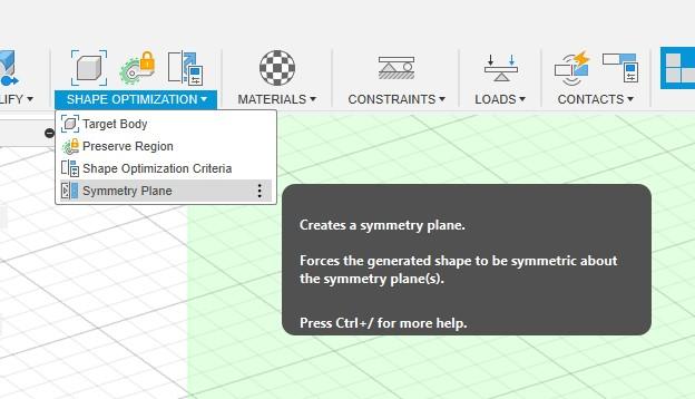
If you want a symmetrical leg (which I do), we can also add a plane of symmetry. If you recall from earlier, we created a plane that divided our model in half (as we needed to mirror the mounting holes). We can select that plane, and use the Symmetry Plane feature to generate a plane of symmetry that cuts down the middle of our part.


Next, we need to add structural constraints. This defines the points that will be fixed in place. In our case, we want to apply constraints to both screw holes, the circular feature on the top of the model, and the point that will be in contact with the table/ground.


Now we need to apply the load. In this scenario, there is only 1 force acting (down from the top), so the magnitude is not relevant (in this specific case, see the bottom of this step for more information*). To add a load, click on Loads > Structural Loads, then select the top face and enter any value greater than 0 into the magnitude field.

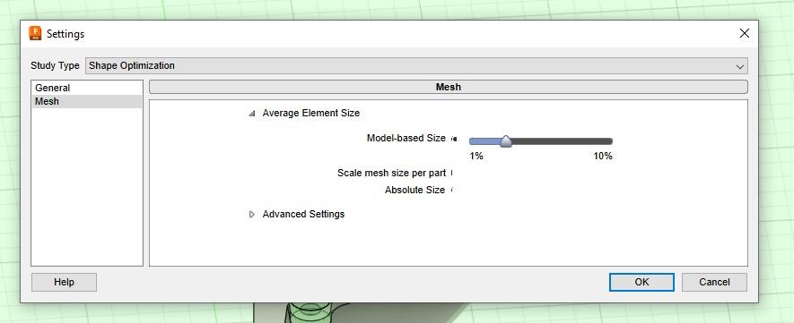
We now want to generate a mesh of our part to make sure everything looks correct. Go to Solve > Mesh to generate the default mesh. More often than not, this mesh is too coarse for the part, reducing the accuracy of the results. To modify the mesh size, we can go to Manage > Settings and use the slider to change the mesh size. Making the mesh size smaller will increase accuracy, but also the time it takes to process the optimisation.


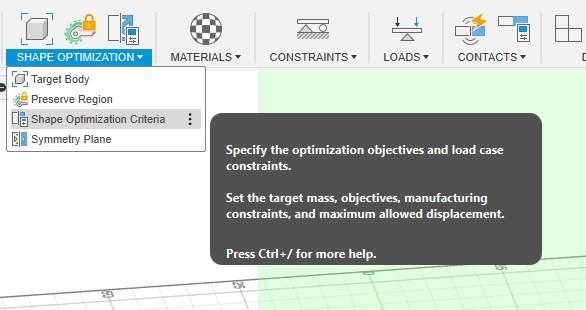
Next, we define the goal of the optimisation. In our case, we want to remove material to save filament and hence money. We can set the goal to around 30% of the original mass however, once the simulation is run we are still able to visually see other weights and choose the best one. We can do this by modifying Shape Optimisation Criteria, and then changing the Target Mass value. We want to keep the target as Maximise Stiffness.
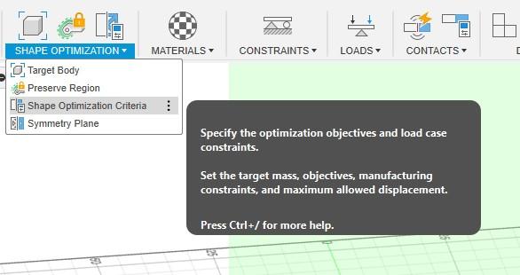

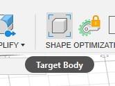
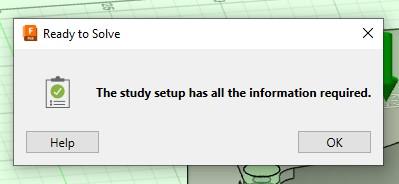
Choose the target body by clicking on the icon in the toolbar and then choosing the leg as the body. Then click on Solve > Pre-Check to make sure there are no errors. If all is ok you should get a message as shown below. Now you can hit Solve and the topology optimisation will begin!


As commented by Leo_LaRoca I thought I'd add a note from him about the magnitude and its importance in other applications and projects:
*Just a quick note, as I've worked with topology optimization before. When you say "so the magnitude is not relevant", although it is true for this specific case, it would be nice to elaborate why, since in some cases it can even be dangerous to not consider the correct load! (For instance, a shelf with heavy, or sharp objects)
Since you are using a stiffness optimization, the algorithm will generate the structure (with ~30% of the original volume -since the material has a homogeneous mass) that has the highest stiffness for that volume. So in this case it is indeed independent from load, since it's just considering your desired volume and the load direction, regardless of material or load magnitude.
But you can clearly see that if this part was made of Styrofoam, it would fail! By default, Fusion360 gives you a generic material (which by itself can be dangerous), but the "correct approach" for a structurally stable end result would be to certify you are using the correct material (double check the elastic modulus and yield stress), constraints and load. And also running a linear elastic simulation afterwards to ensure the part is not getting close to its yield stress.
Troubleshooting (Educational Licence)
If you are on an educational licence for Fusion360, you should have unlimited access to topology optimisation for free. However, I struggled for a loooong time with this. It took me hours to figure out why it didn't let me run my simulation due to "insufficient cloud credits". So let me step you through the issue I had and how you can overcome it.
Fusion provides educational users with 2 licences. This means you need to access your user preferences (by clicking the person icon in the top corner) and go to Token & Cloud Credits. You will then see your 2 accounts listed as well as some options to choose which account to "charge" for the use of cloud credits. You should set all the options to Education so that it charges your unlimited bank of cloud credits. If you are using educational cloud credits, simulations may take longer as they are flagged with a low server priority (mine still only took a few minutes as they were quite simple designs).

Results
If the optimisation goes as planned, you should now have a beautiful and futuristic-looking part right in front of your eyes! You can change the weight ratio by modifying the slider on the right-hand side. You can see this in the video above. Once you are happy with the way it looks, and you think the part will be strong enough, you can promote your results back into the design workspace as a mesh model.

Refining the Model
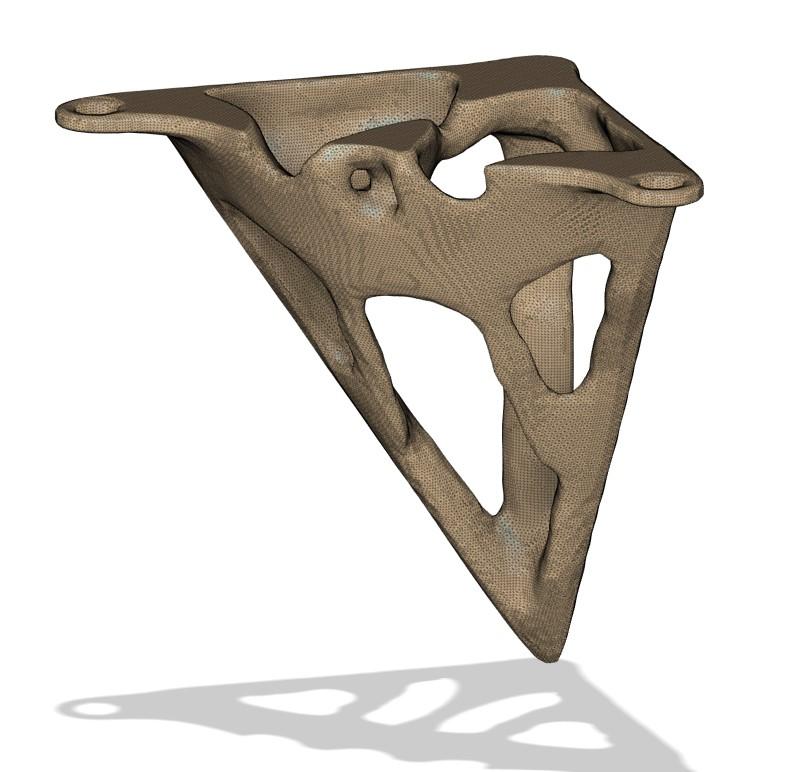
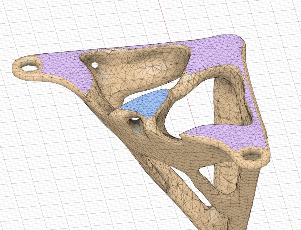
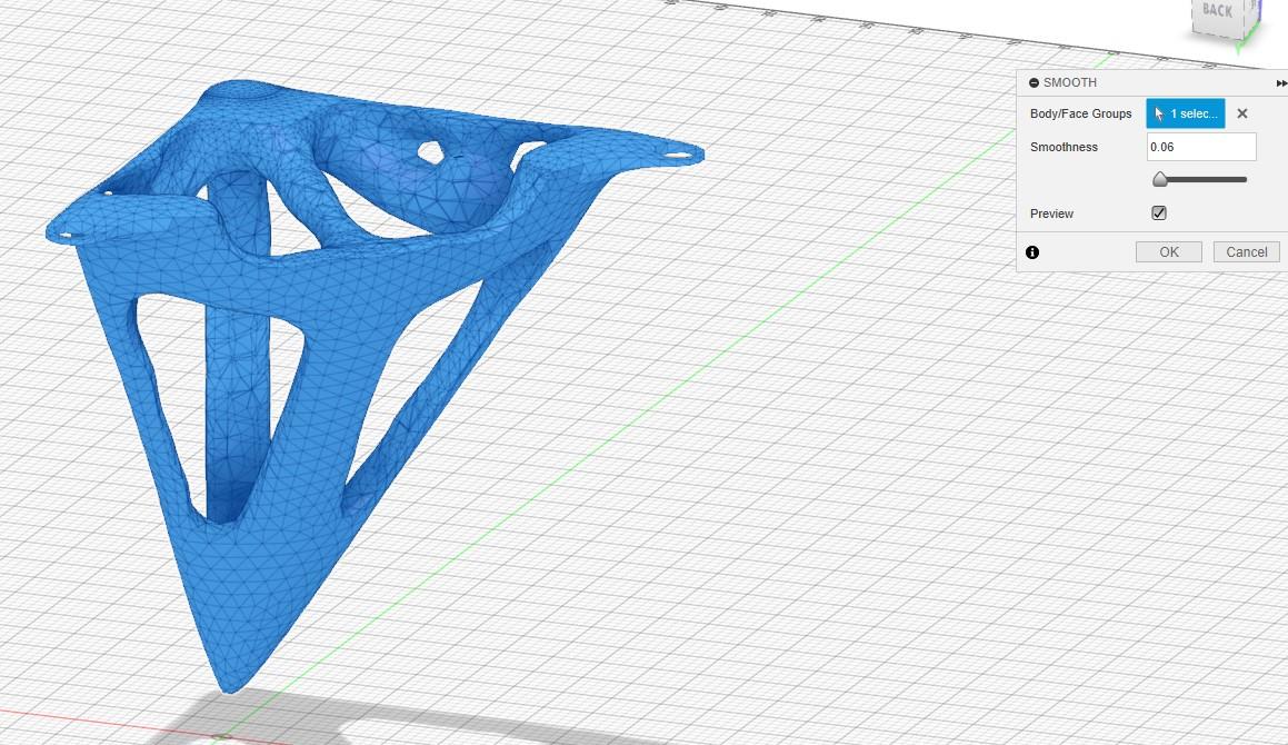
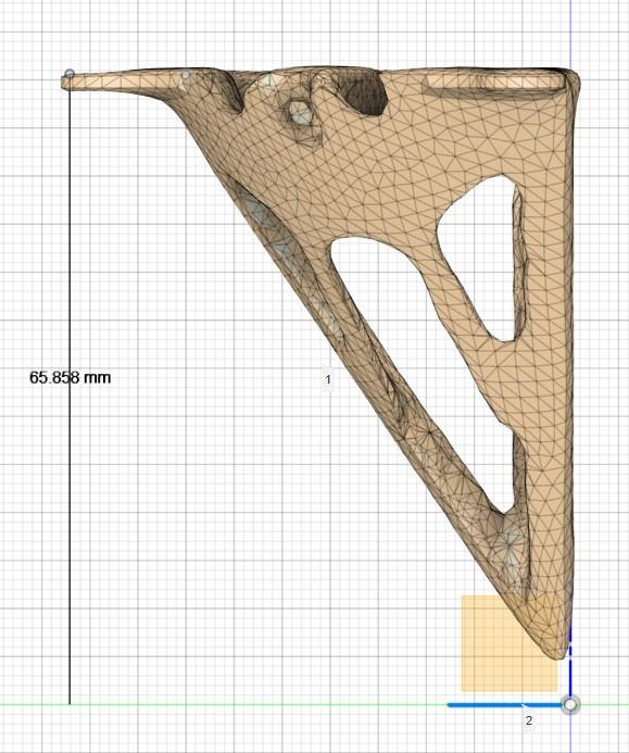
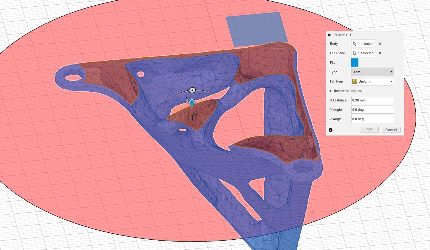
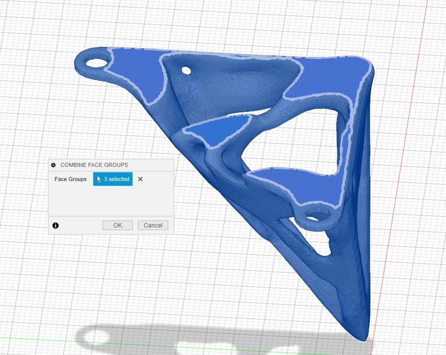
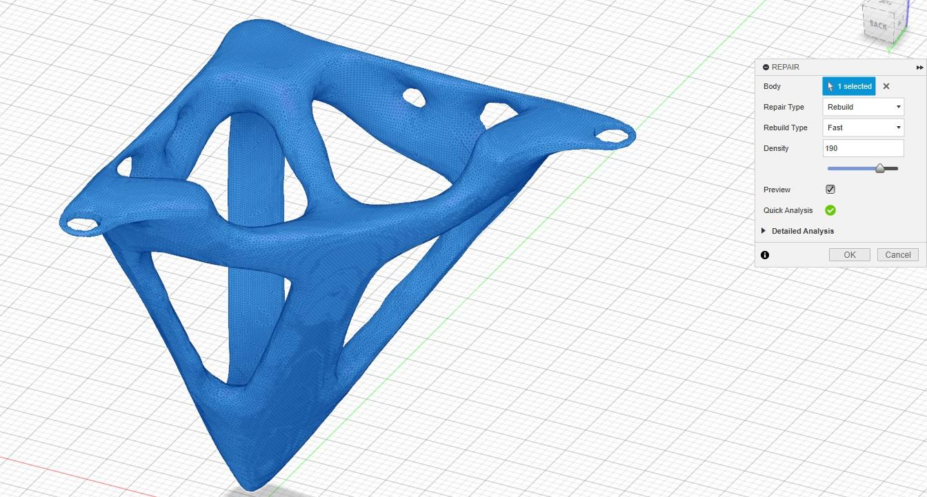
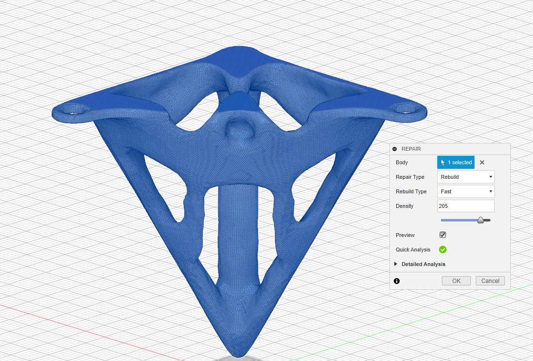
Having successfully generated a mesh body, we need to refine it to improve the print quality as much as possible. First, use the Smooth feature to improve the mesh quality.

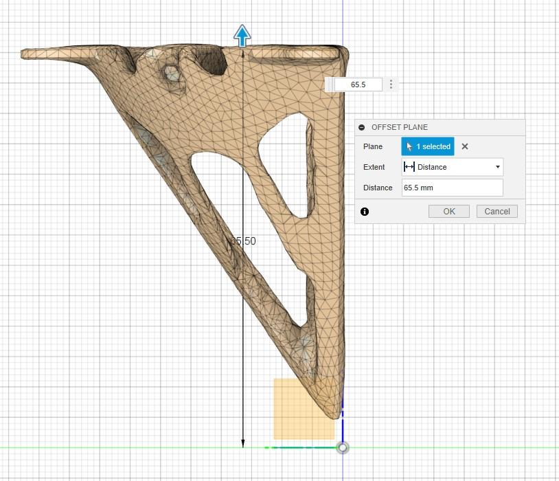
Since excess material protrudes above the mounting holes, we must remove it to ensure the leg sits flush with the top plate. Use the Inspect tool to measure the distance from the base plane to the top of the mounting holes. Then create an offset plane slightly under that height.


We can then use a plane cut on the offset plane we just created, fine-tuning the height of the cut using the numerical input fields.

After you cut the top flush, you need to combine the face groups. This can be done with the combine face group feature. Simply select the main body and all other faces and combine them into a single mesh.


Finally, you can use the repair feature to smooth out any imperfections. Once you are happy with your mesh, just right-click on your mesh body in the component browsing tree and hit save as mesh (this will save it as an STL for 3D printing).


3D Printing
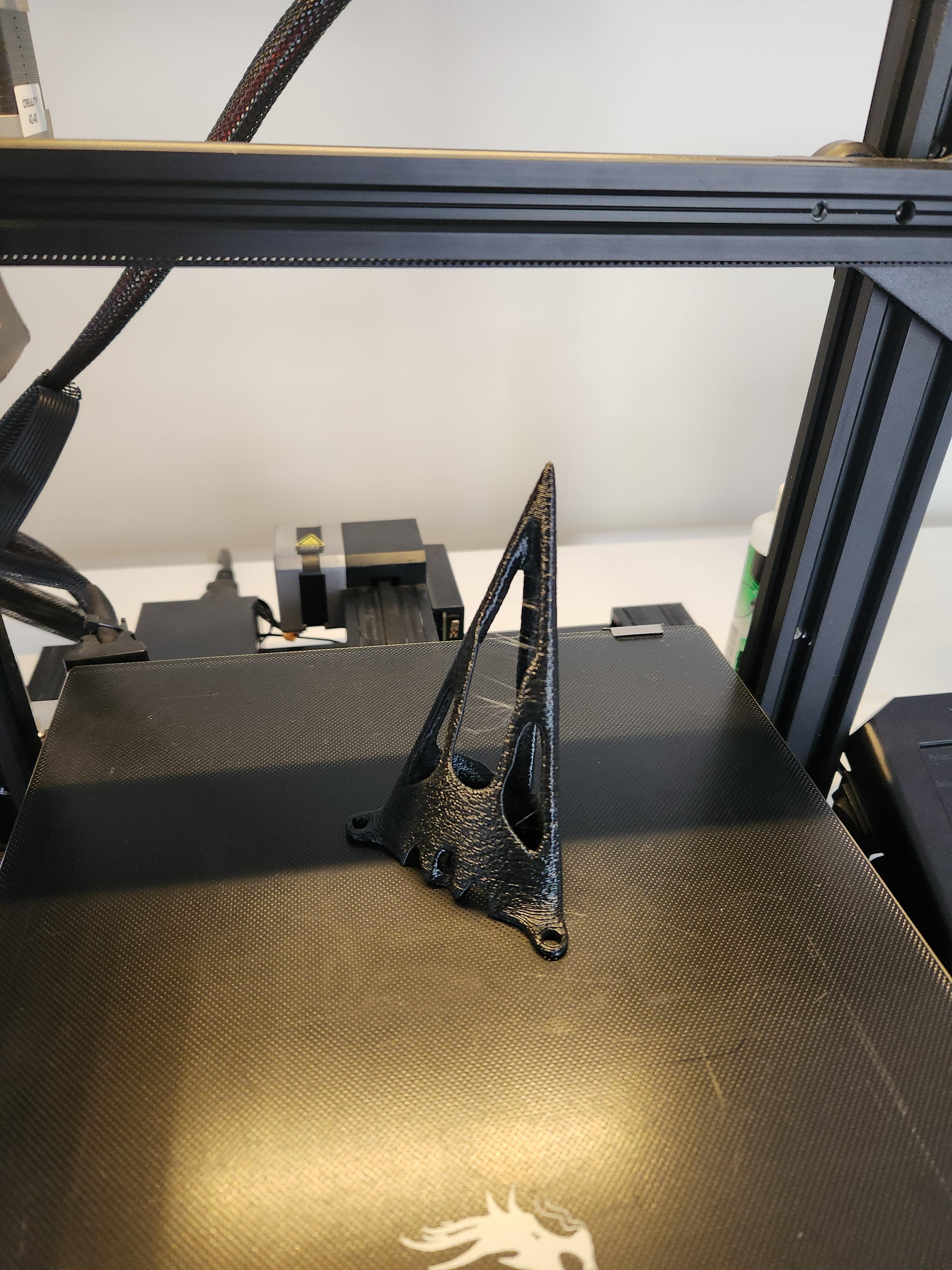
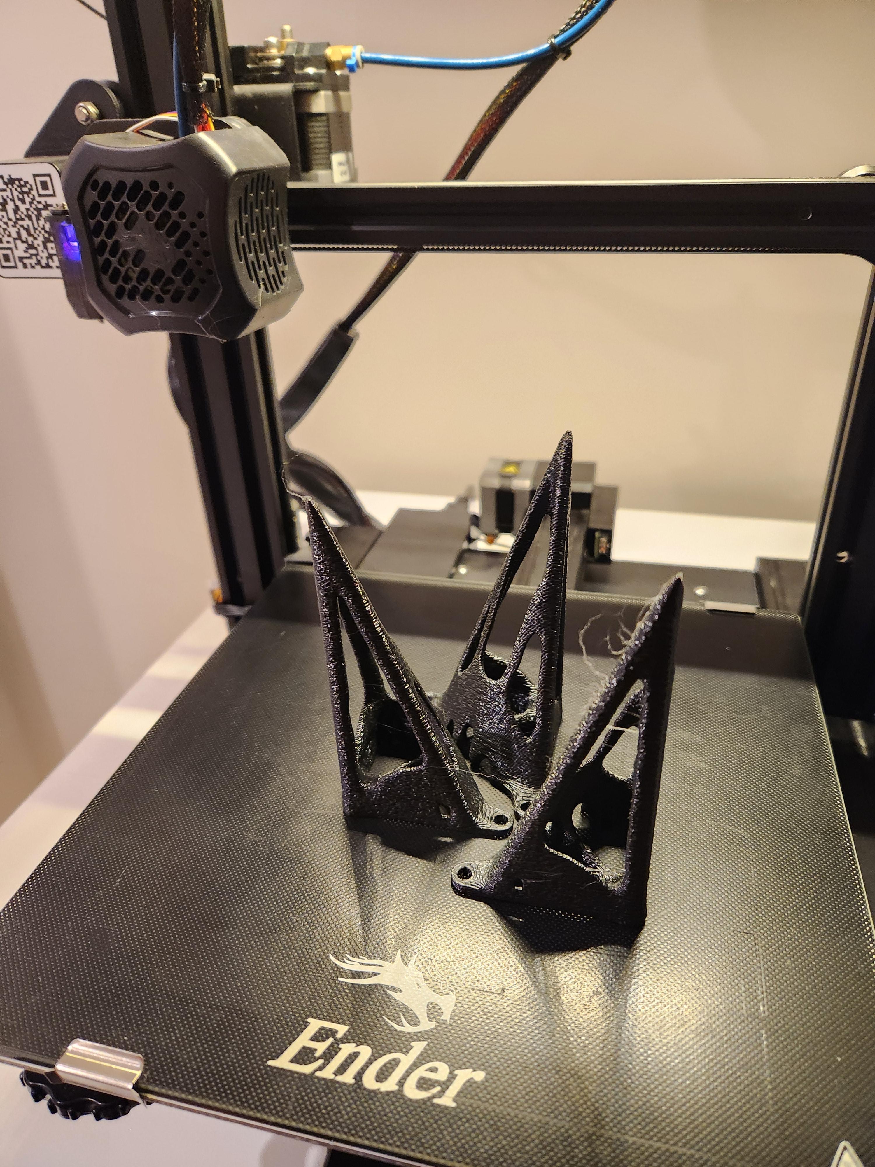
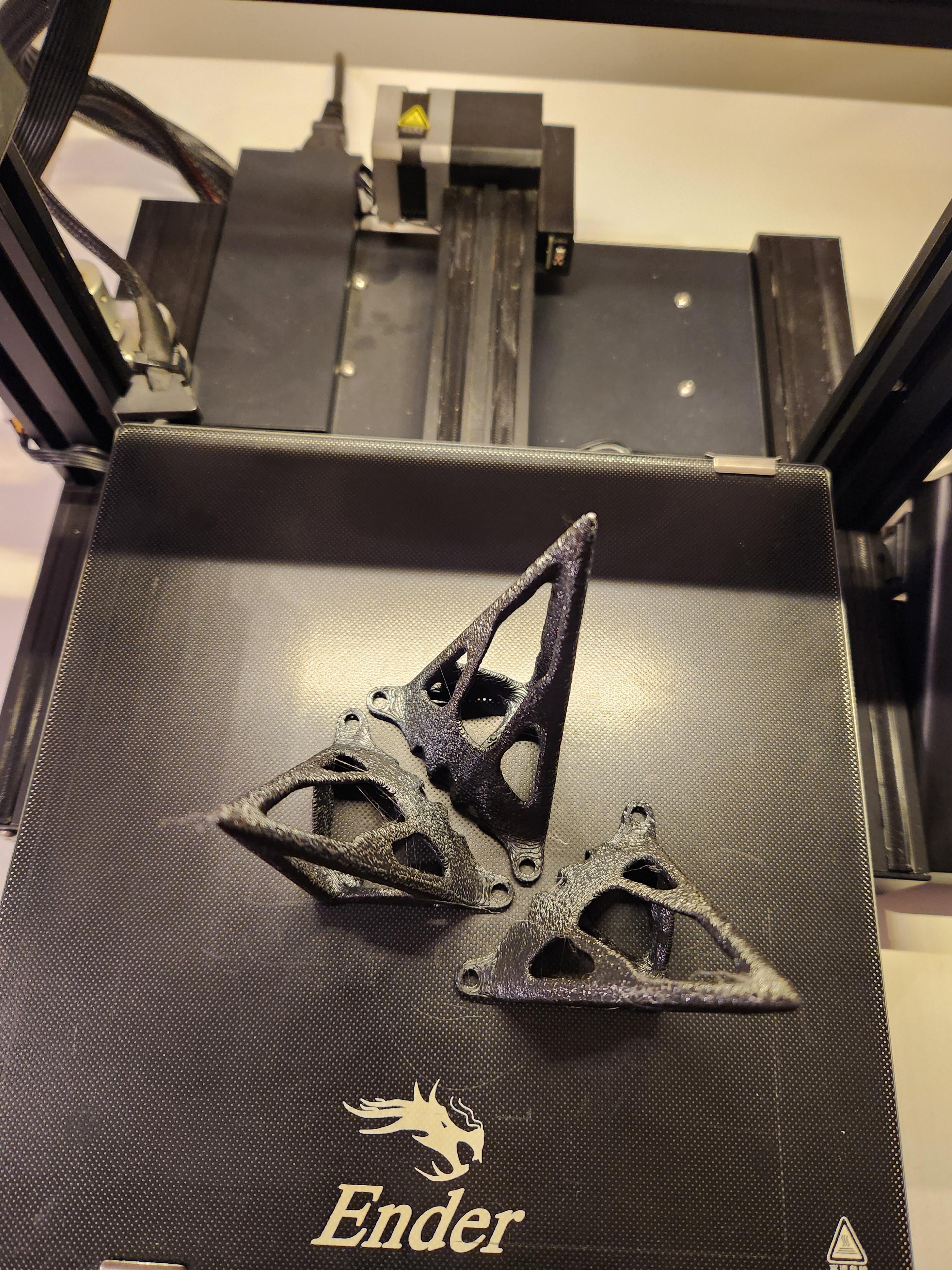
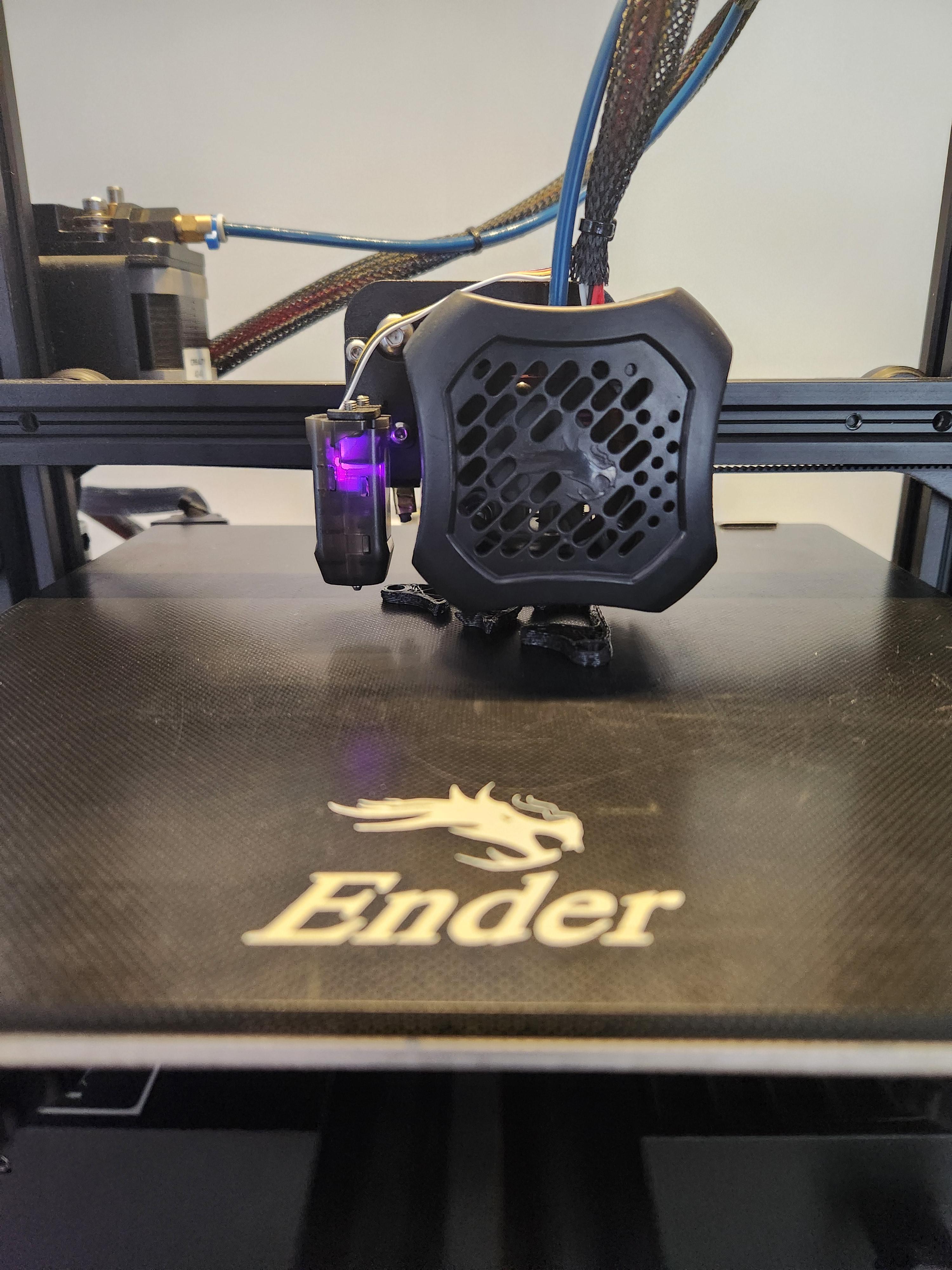
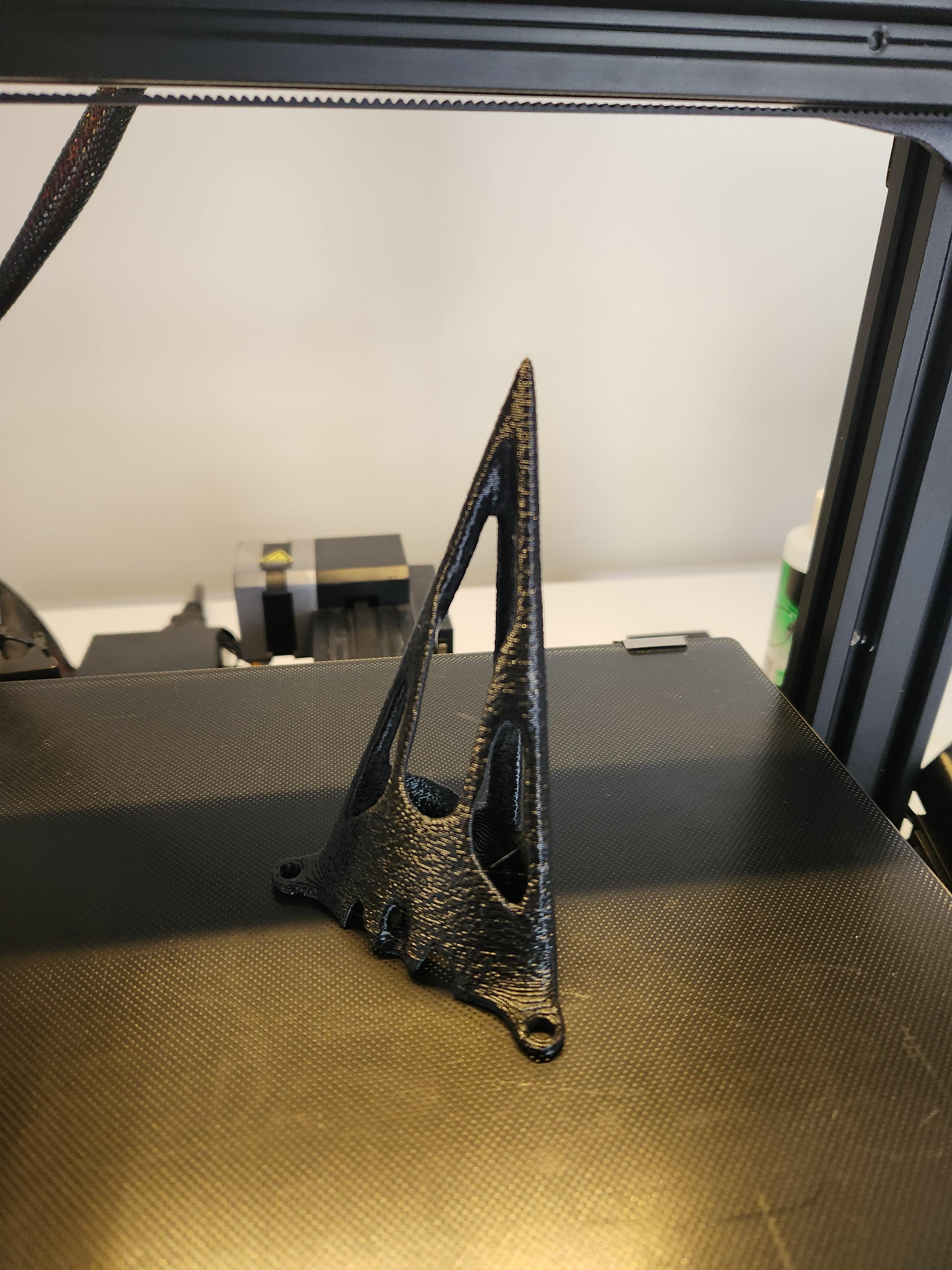
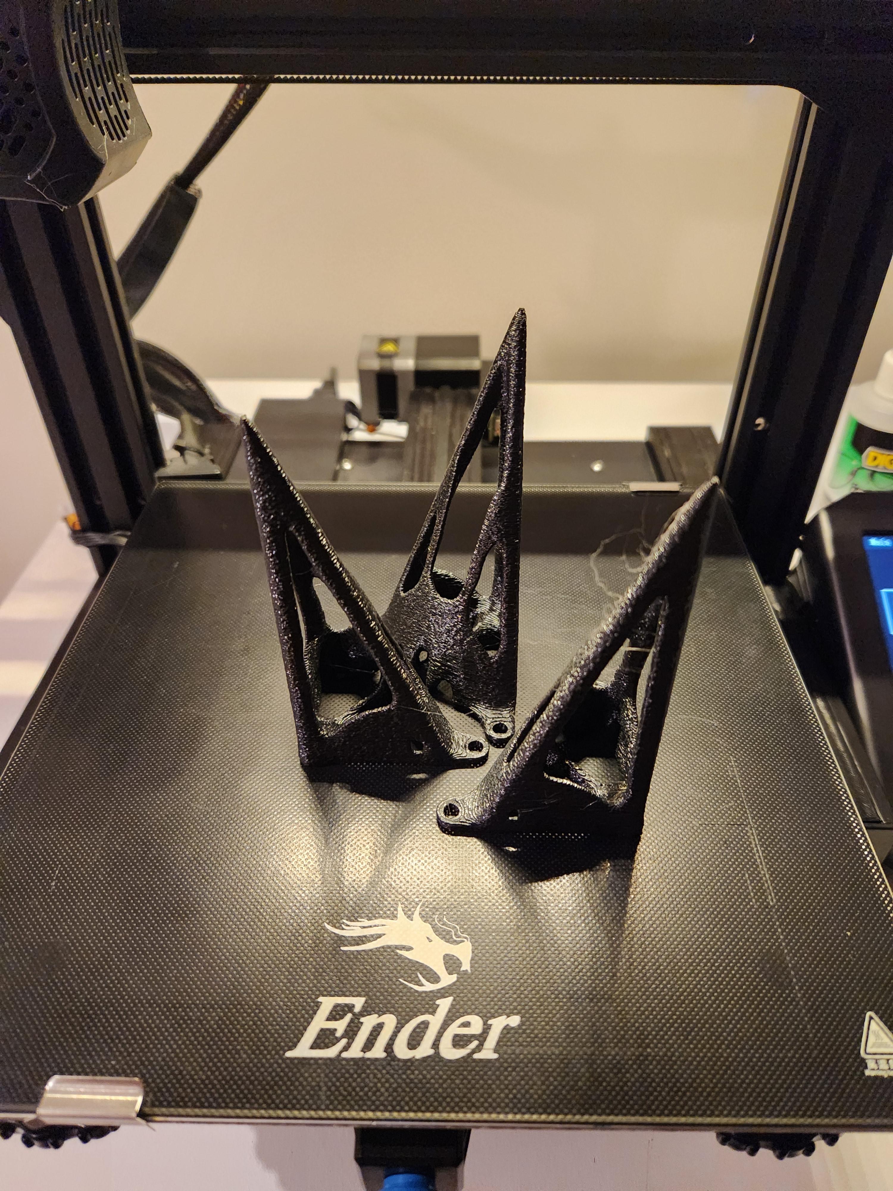
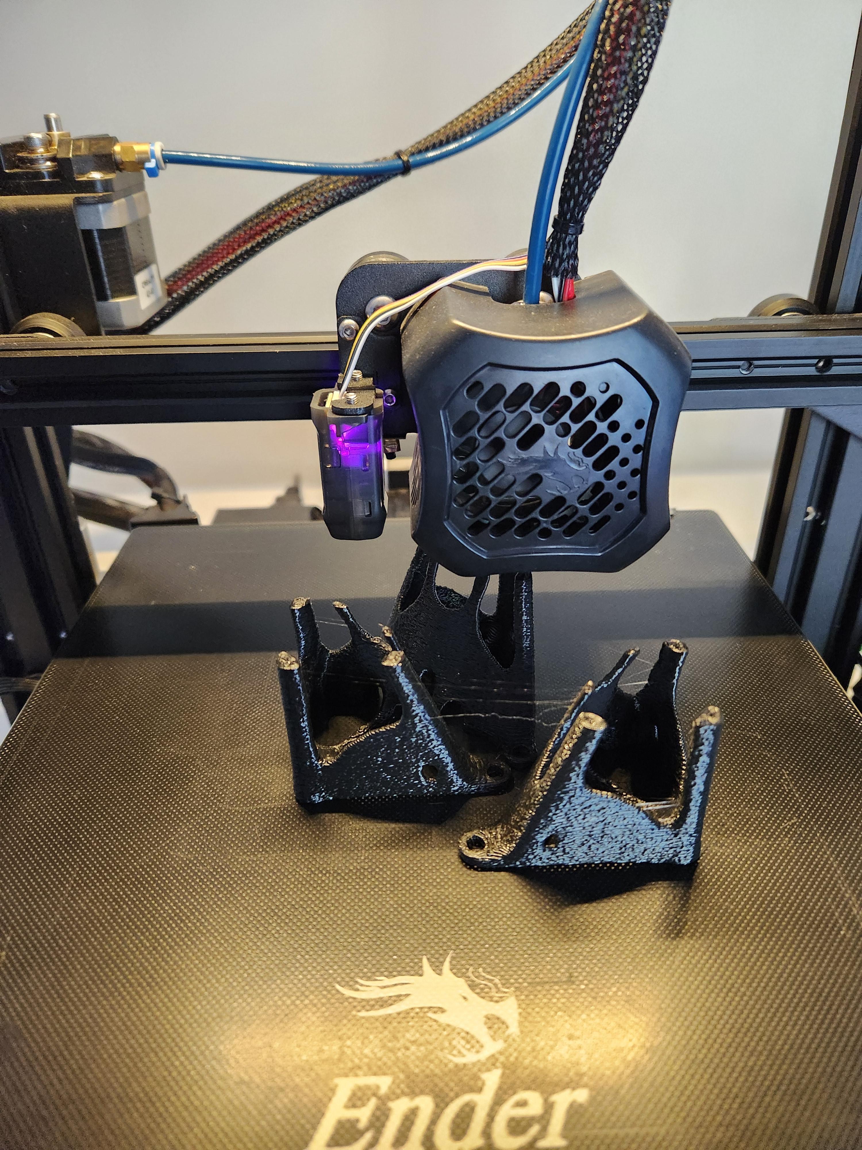
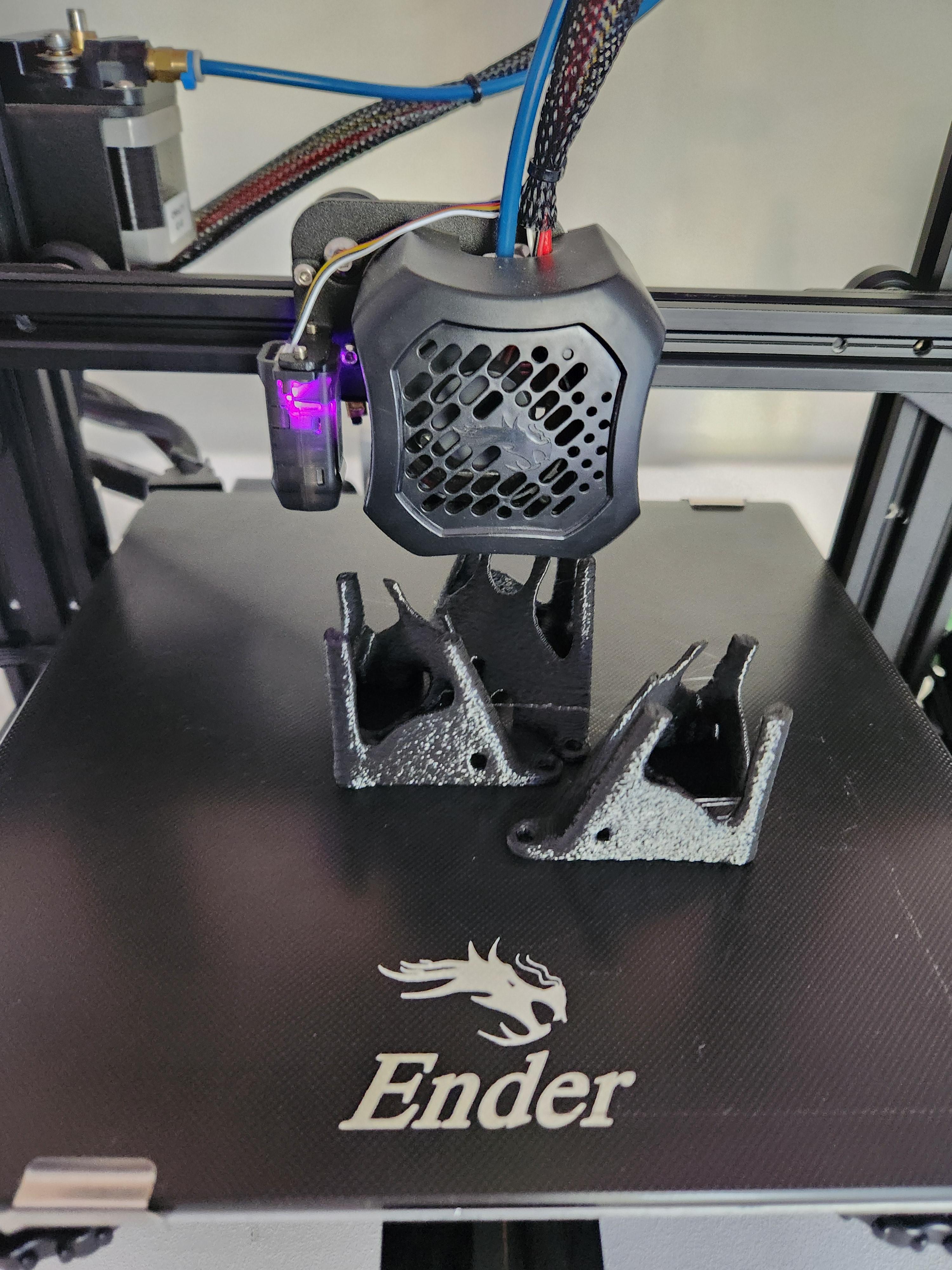
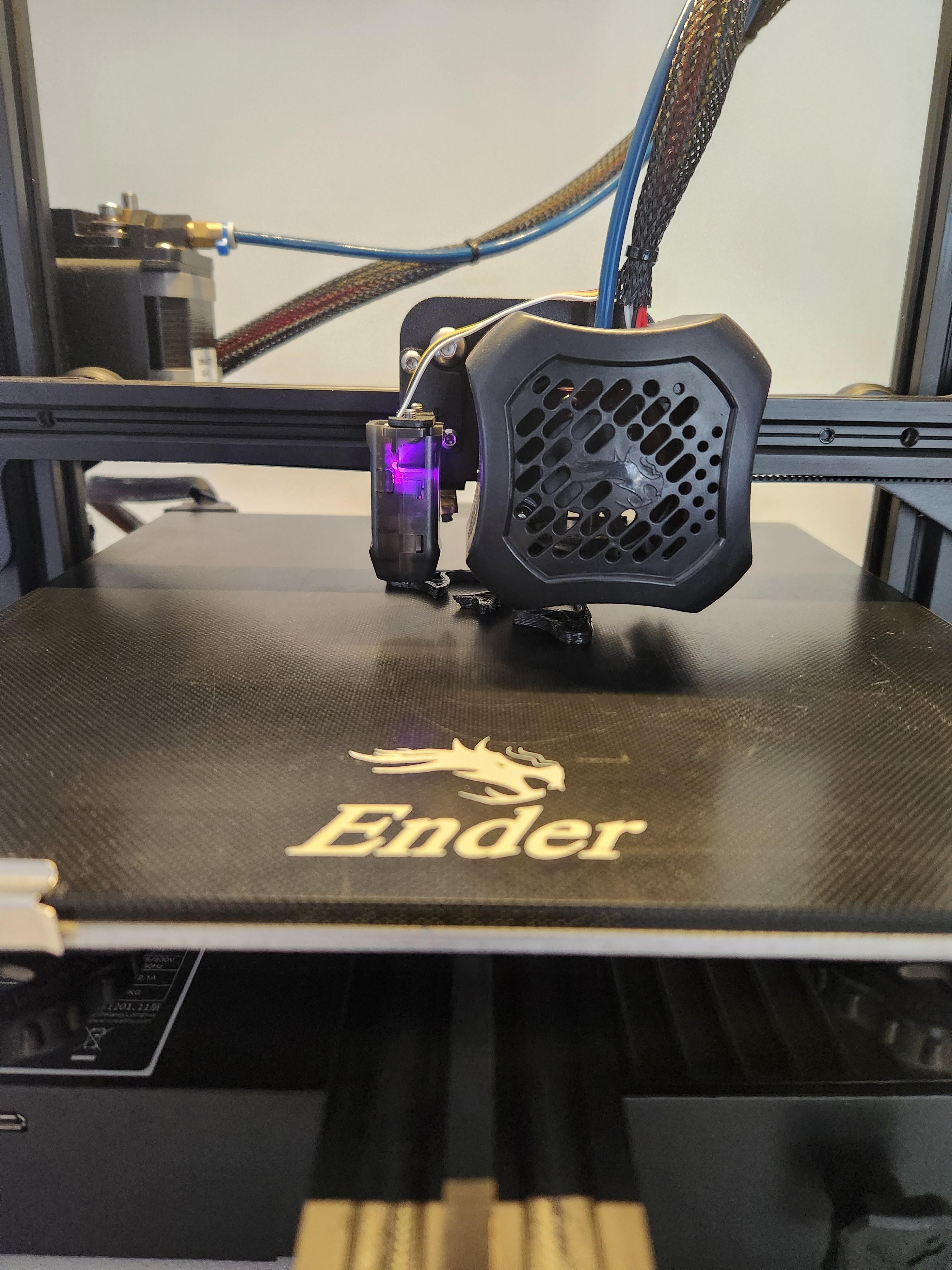
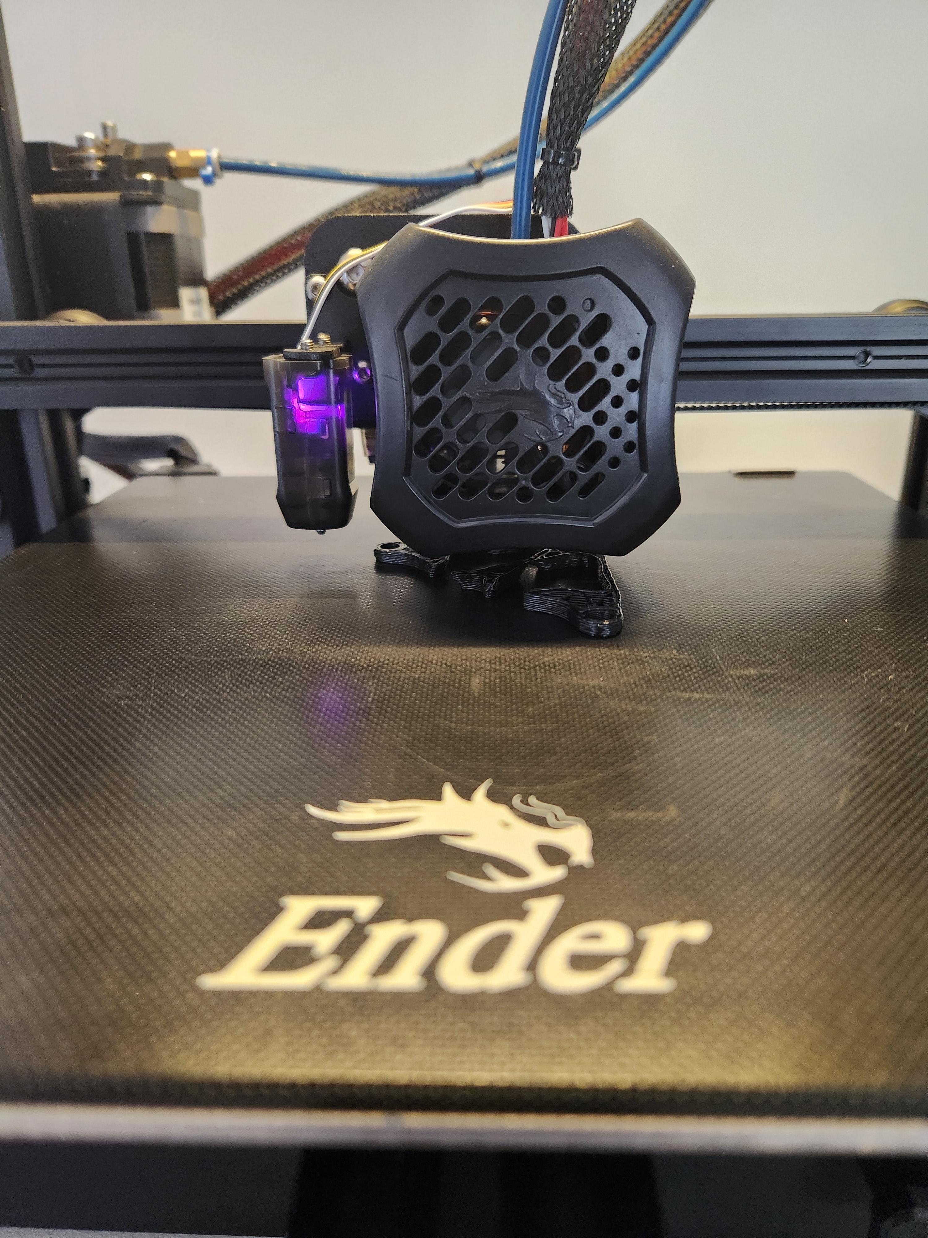
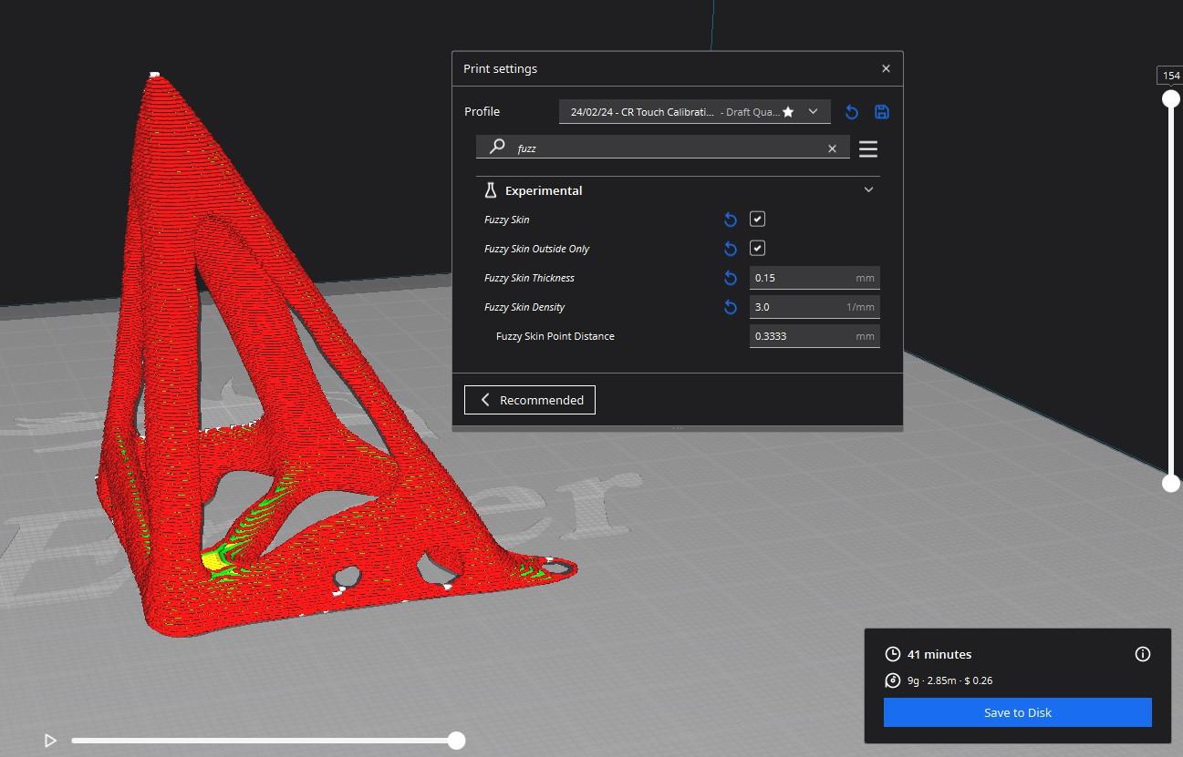
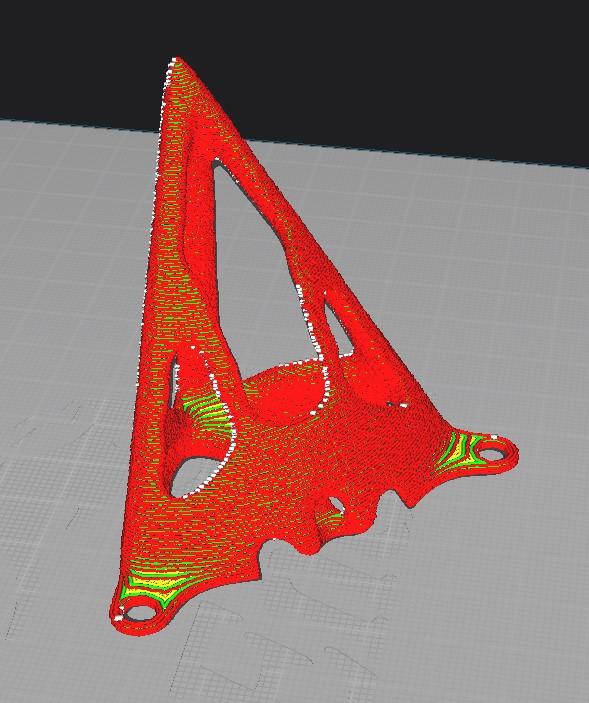
Now that your model is finished, it's time to get printing!
If you want the files I designed, you can find them on printables here: STL FILES
After loading the STL into your slicing program you simply need to orientate it such that the point faces upwards. If you are lucky, your design might not require any support material. In my case, I did not need any supports and I also had enough surface area for the part to stick properly to the print bed. I have come to love the fuzzy feature in Cura that gives a cool texture on the outside of prints, this not only makes them feel and look unique but helps to hide layers too!
The last step is to scale the model to get the correct height. I did not uniformly scale my leg as I wanted to save material where possible and the stretched design reduced the overhangs further (eliminating any possible need for support material).
Print one leg first to make sure that it prints properly and that it seems strong enough. I originally used 20% infill but decided to step it up to 70% given the topology optimisation had already removed a large chunk of material, however I think the 20% infill was strong enough. Once you are happy with your print you can print out the remaining 3 legs.
Putting It All Togeather
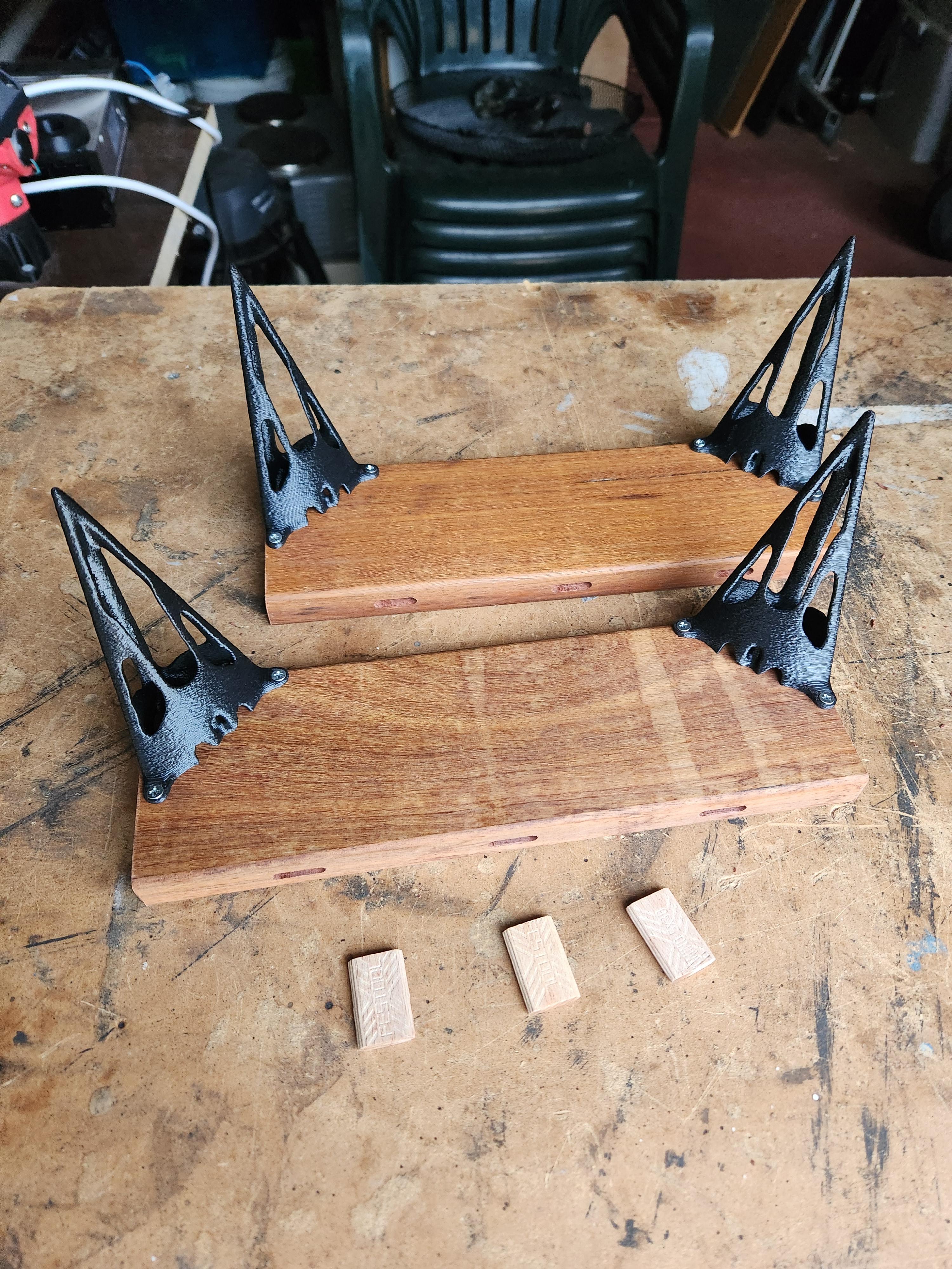
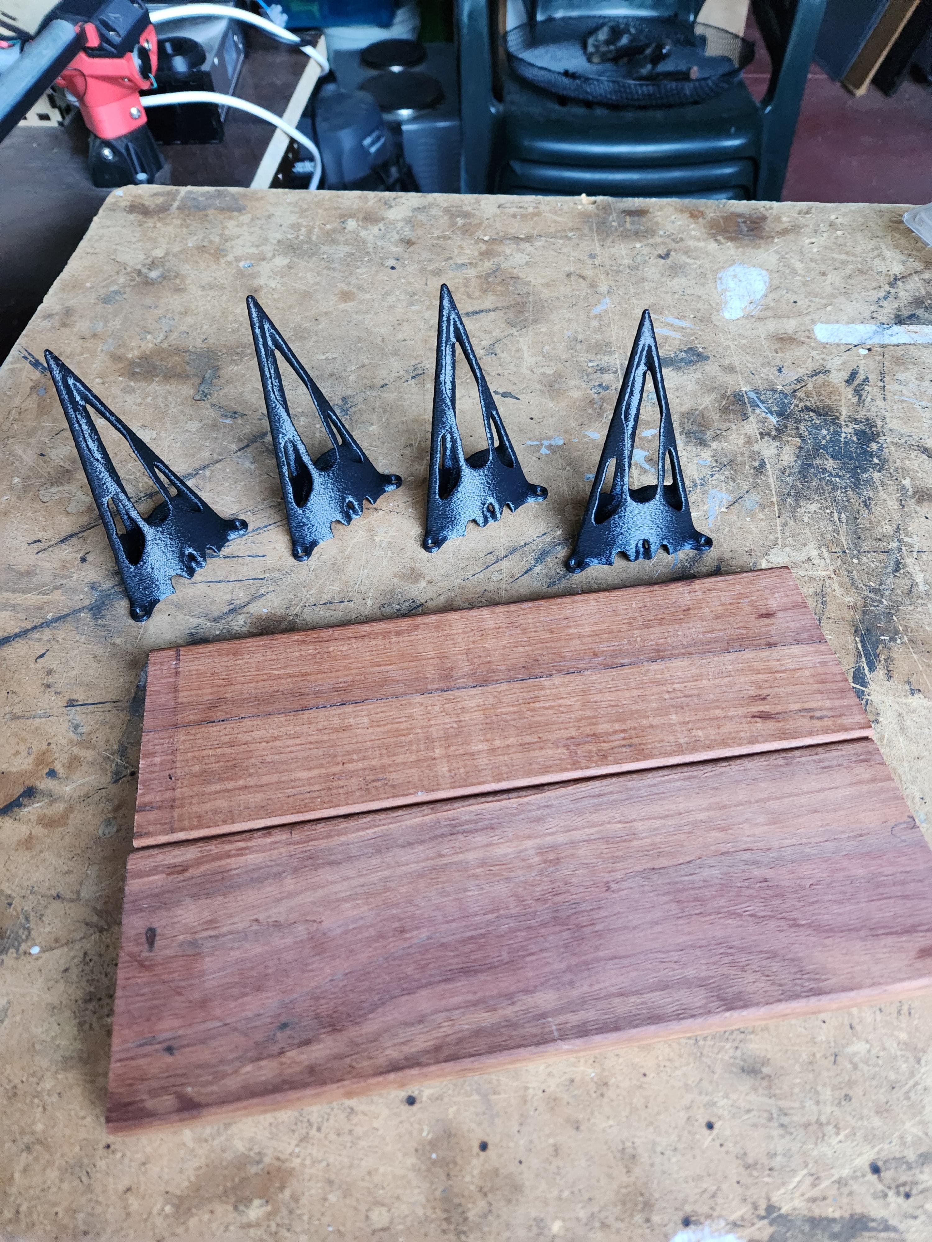
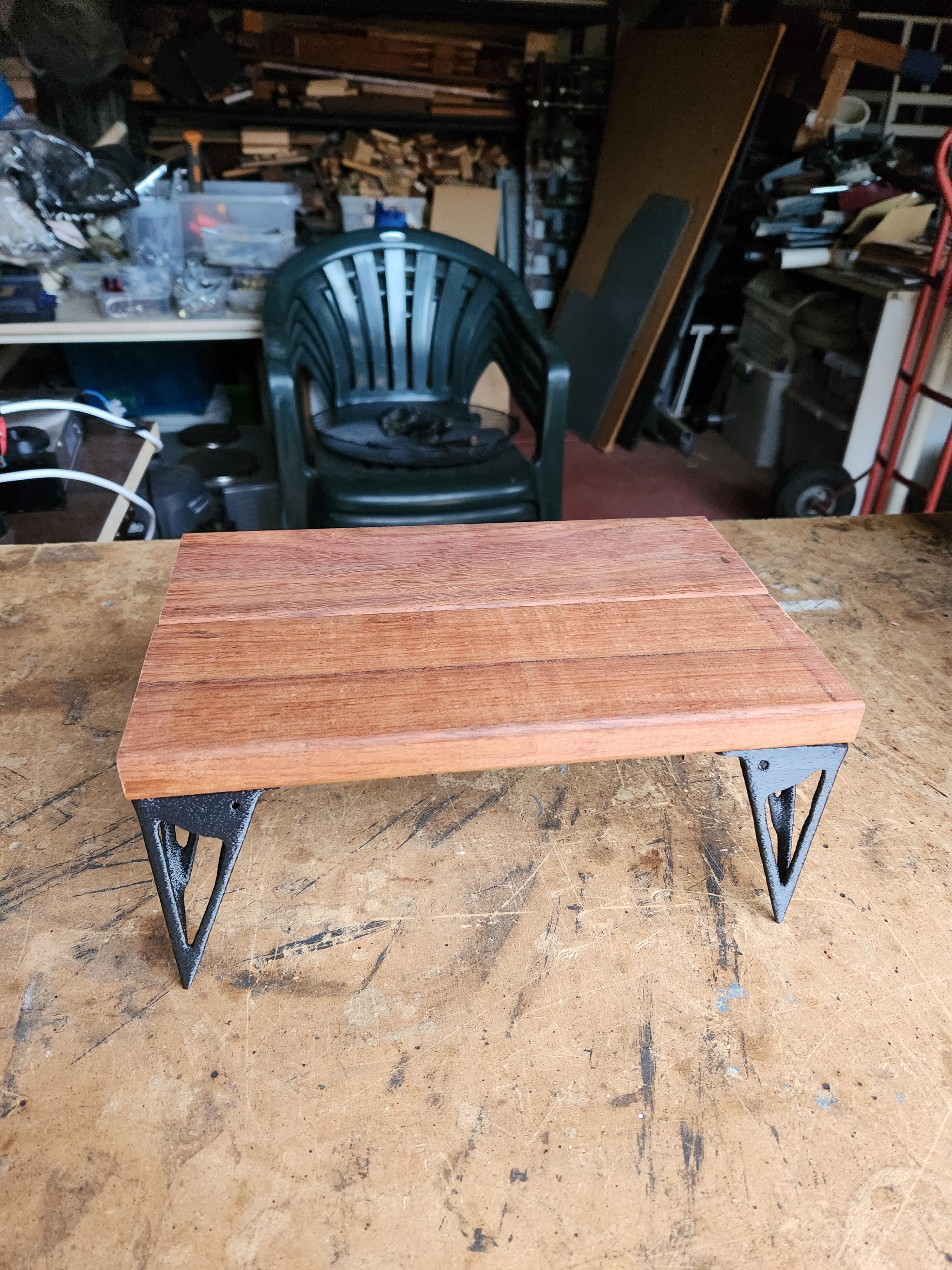
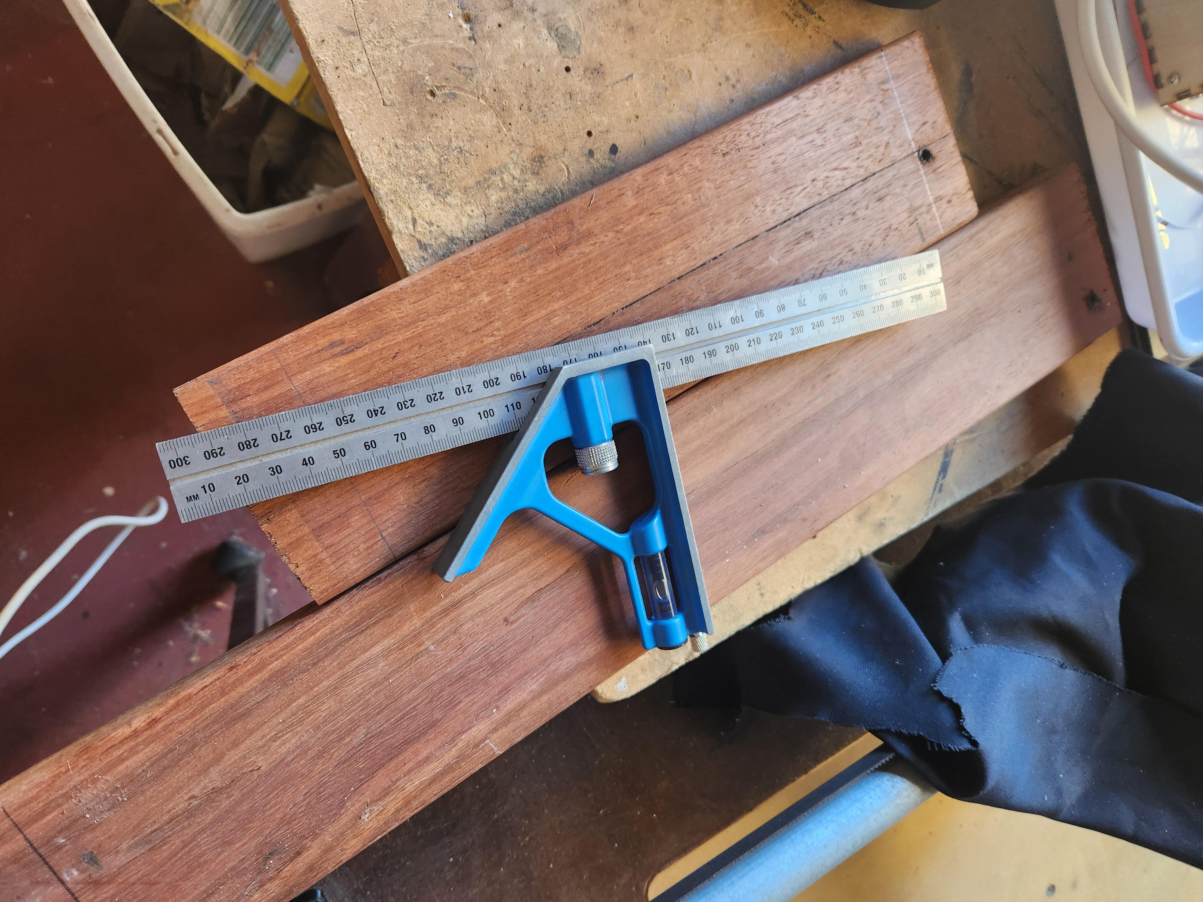
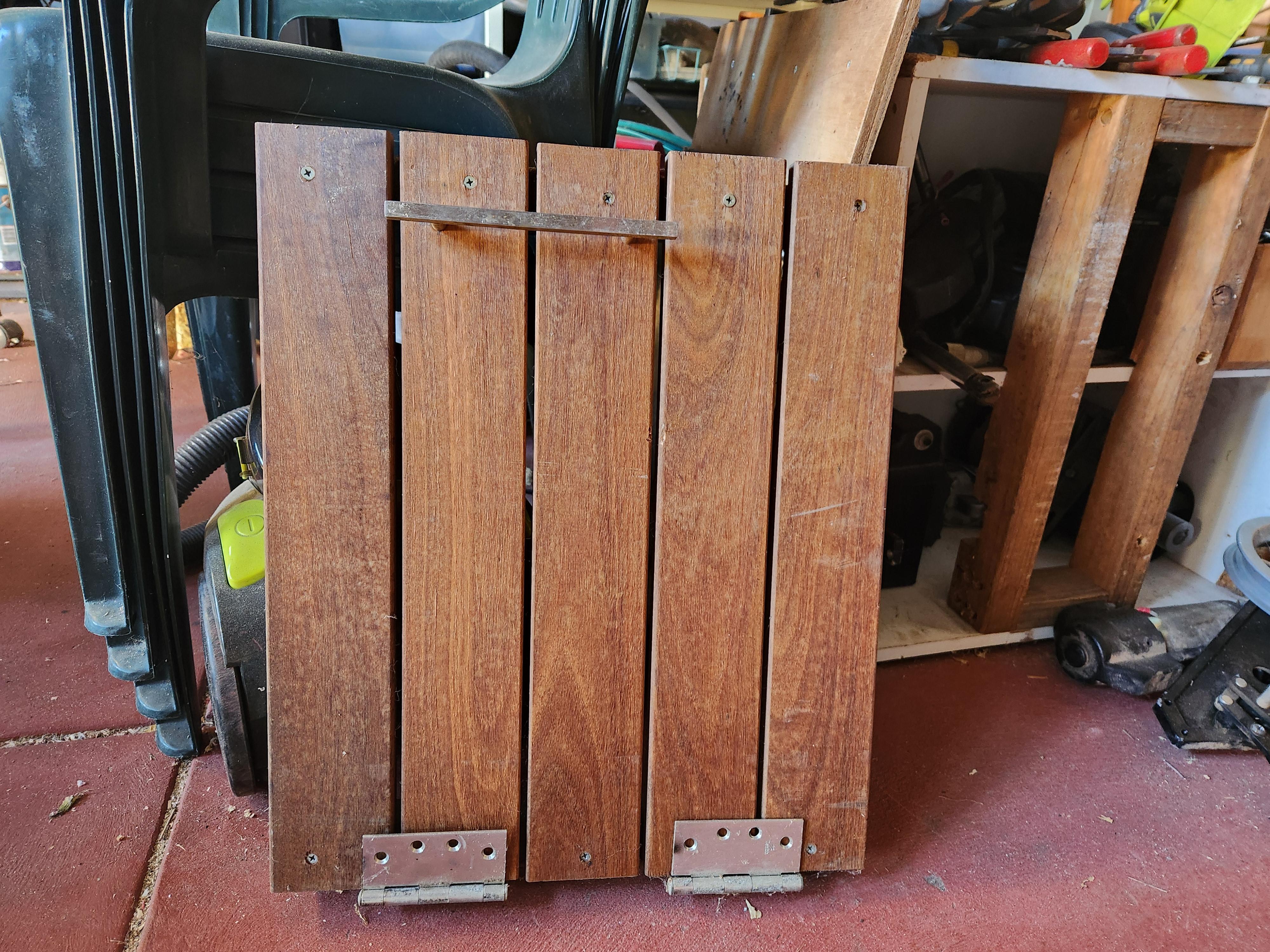
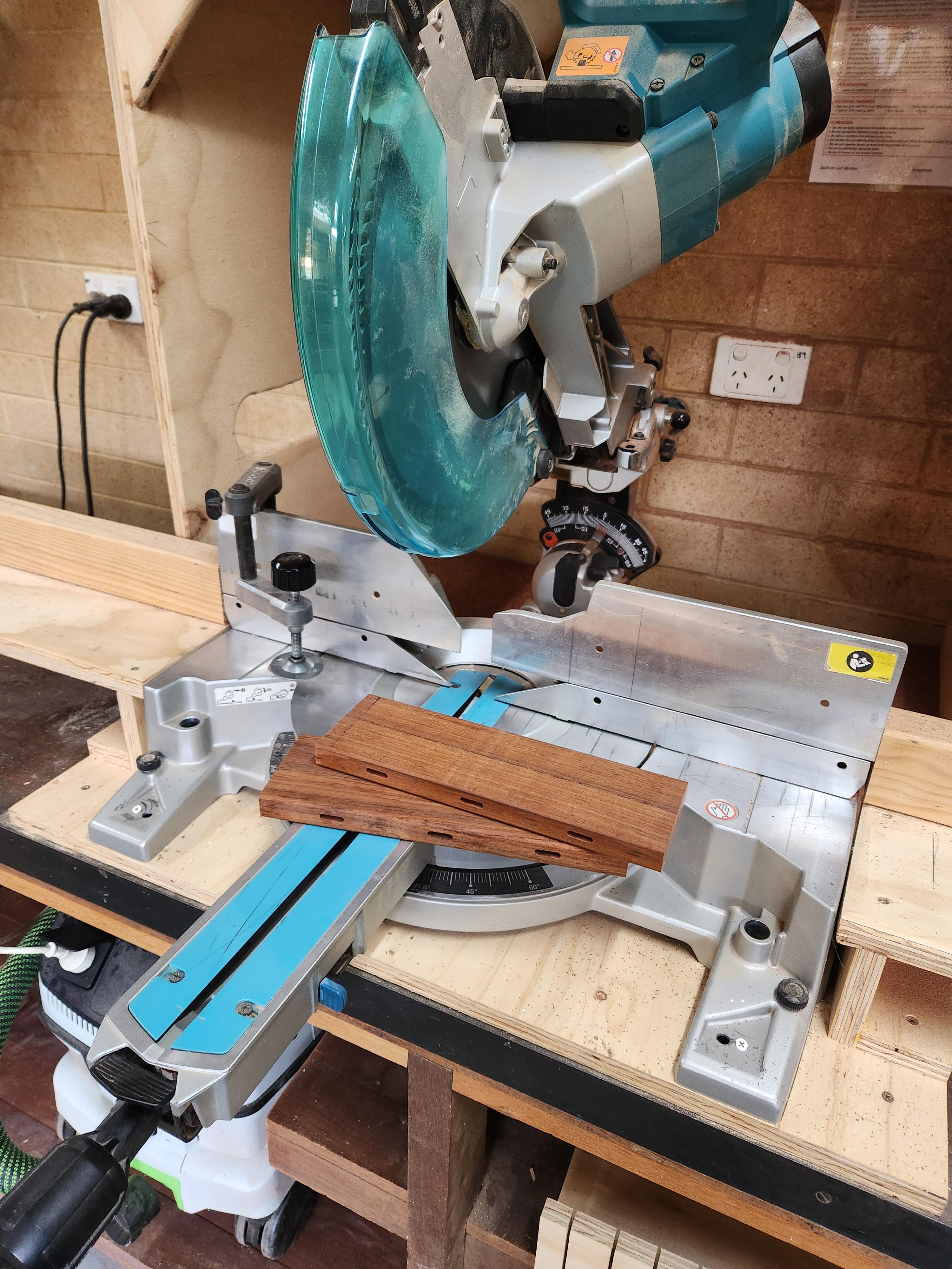
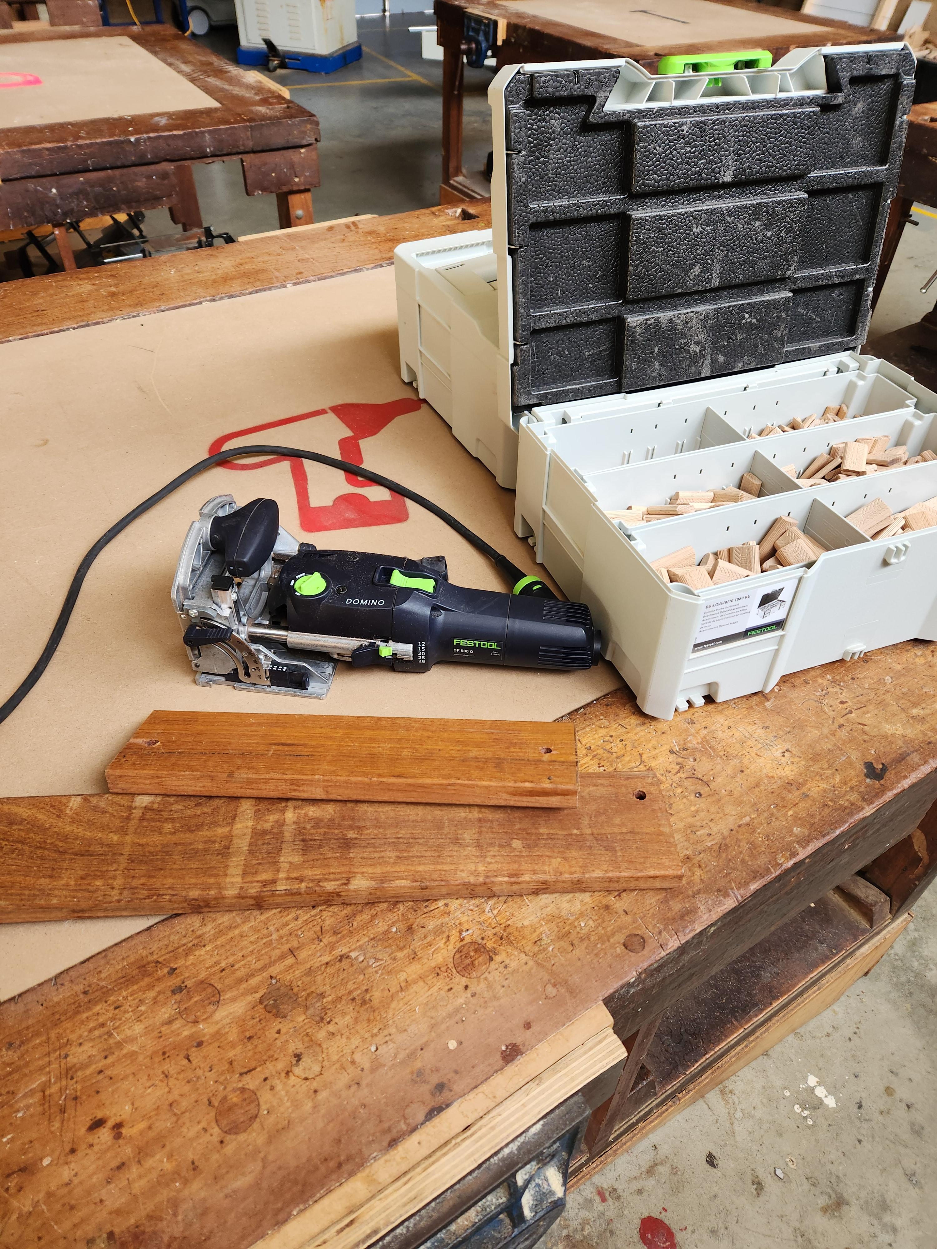
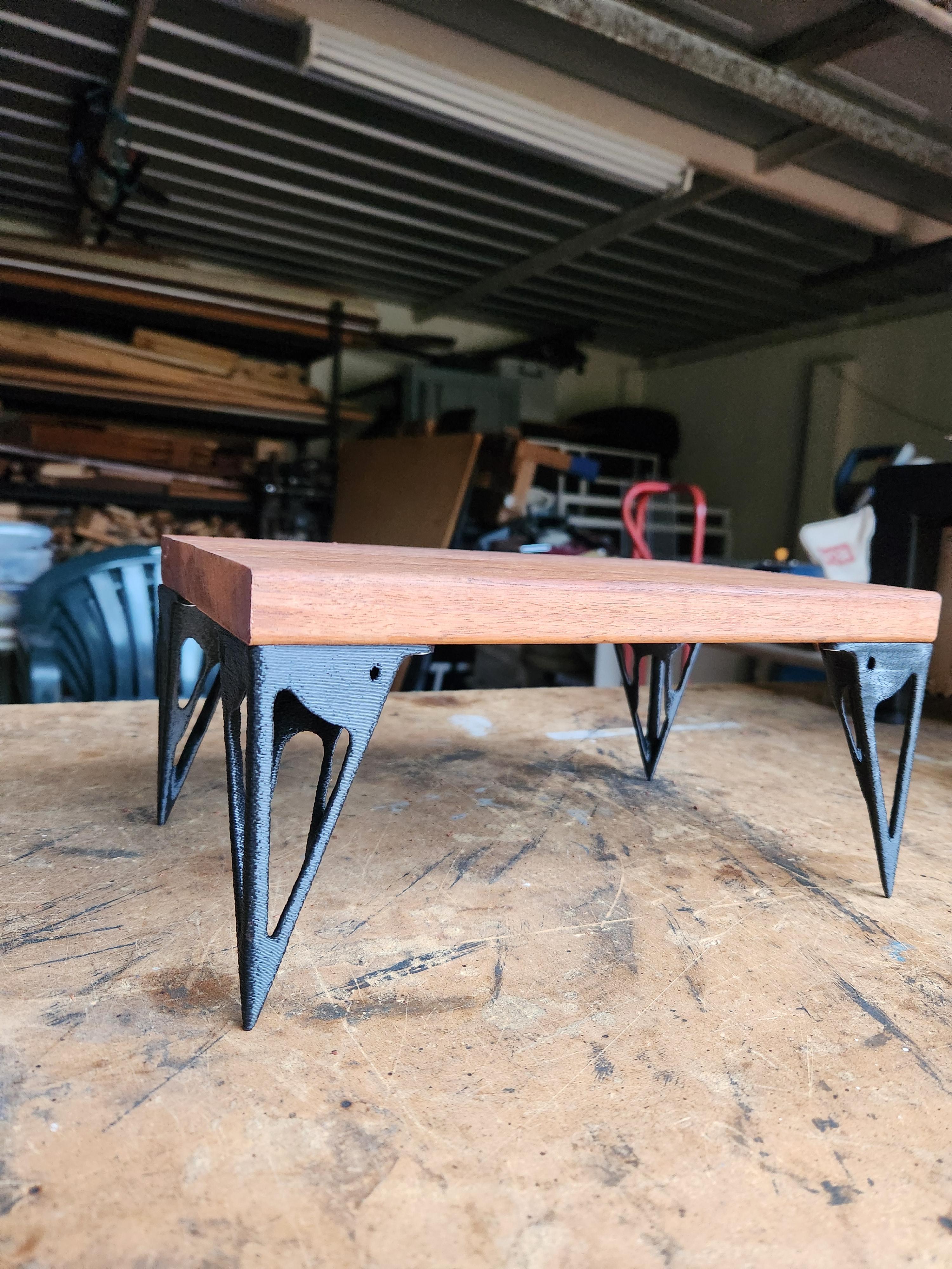
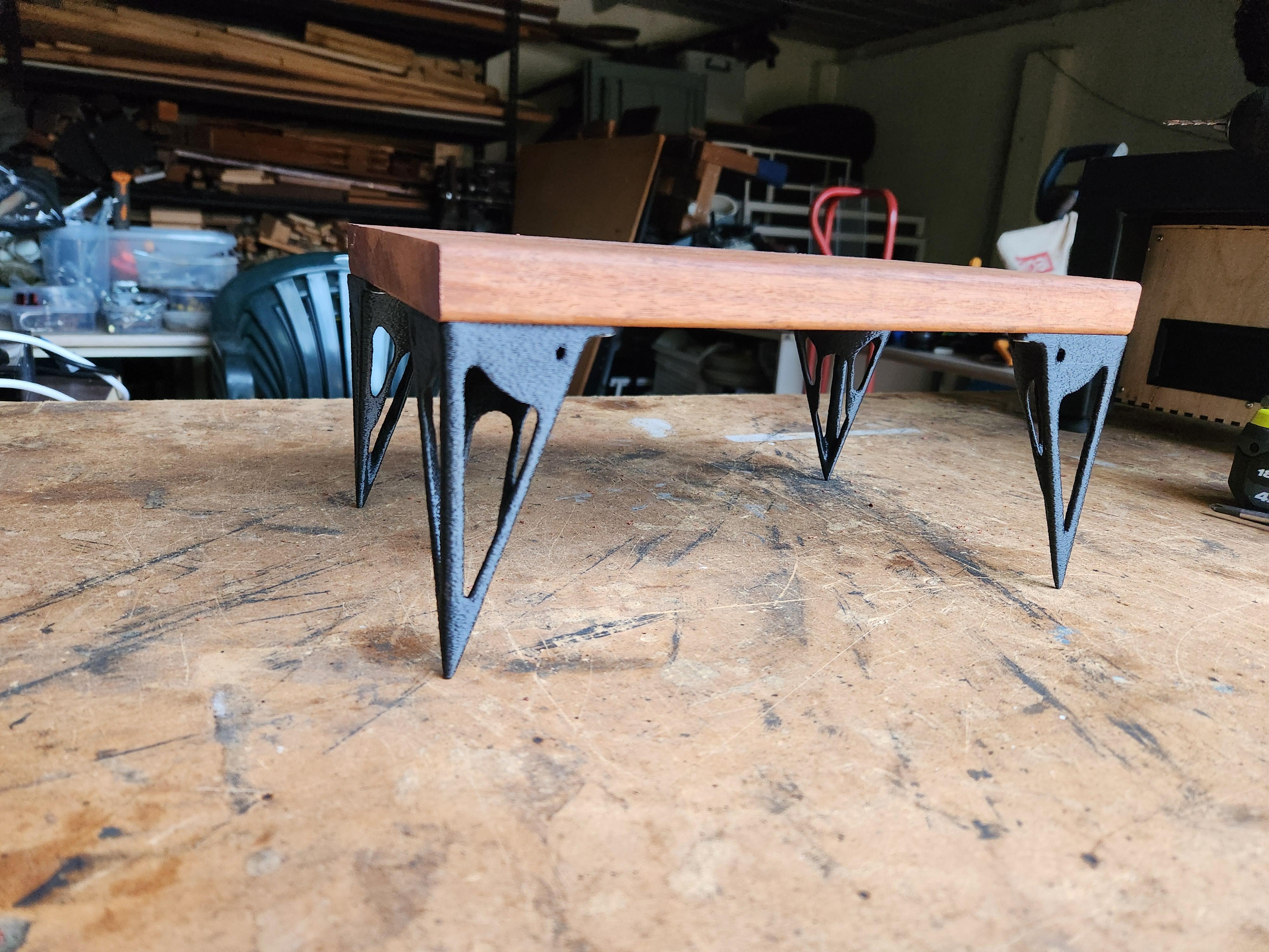
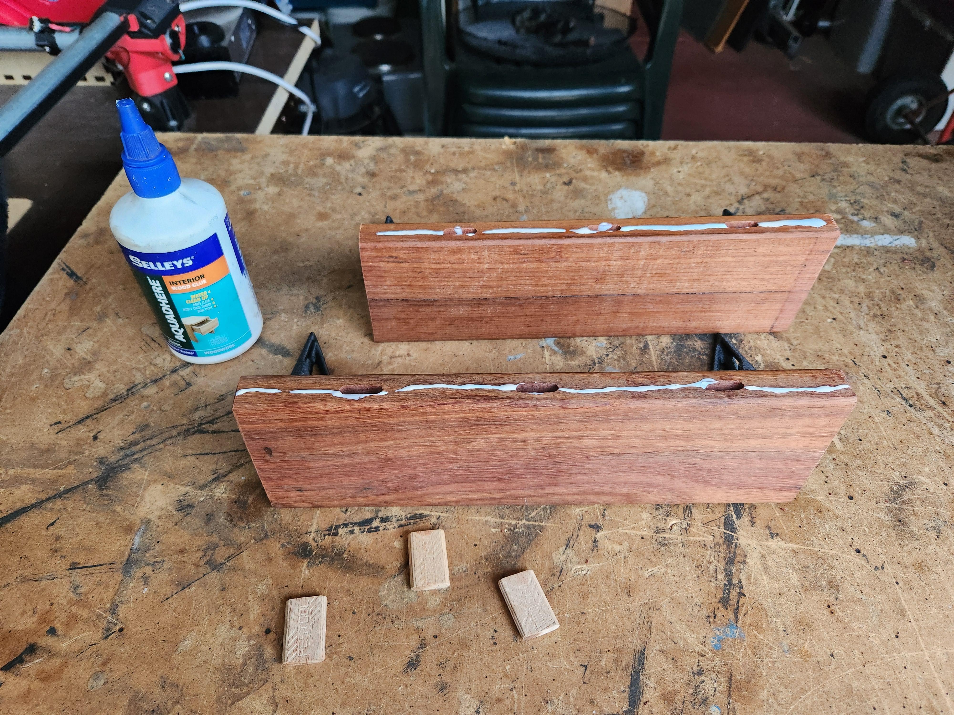
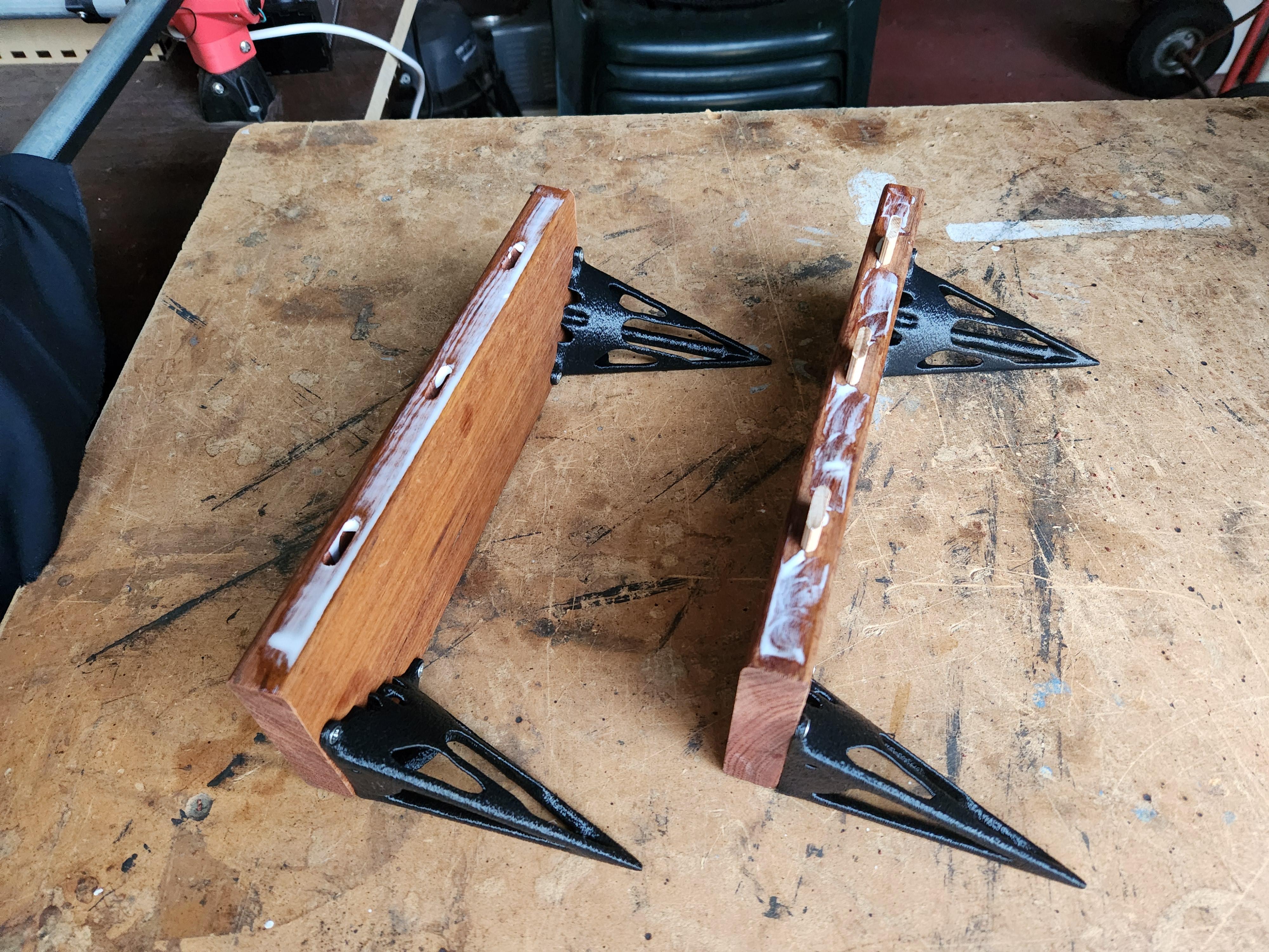
To make the top all you need is a piece of wood. I wanted to make it out of a nicer wood than just PLY so I took some salvaged planks I had lying around from an old sink door (that I salvaged some time ago). Since the planks were not wide enough for the base of the monitor I needed to join 2 of them together. Because I have access to some tools at my school, I ended up using a domino jointer and mitre saw to join the 2 pieces of wood together and cut them to the desired length. However, if you do not have a domino jointer you could:
- Use a biscuit joiner (since they are cheaper)
- Use another strip of wood or metal on the underside to screw into both pieces of wood


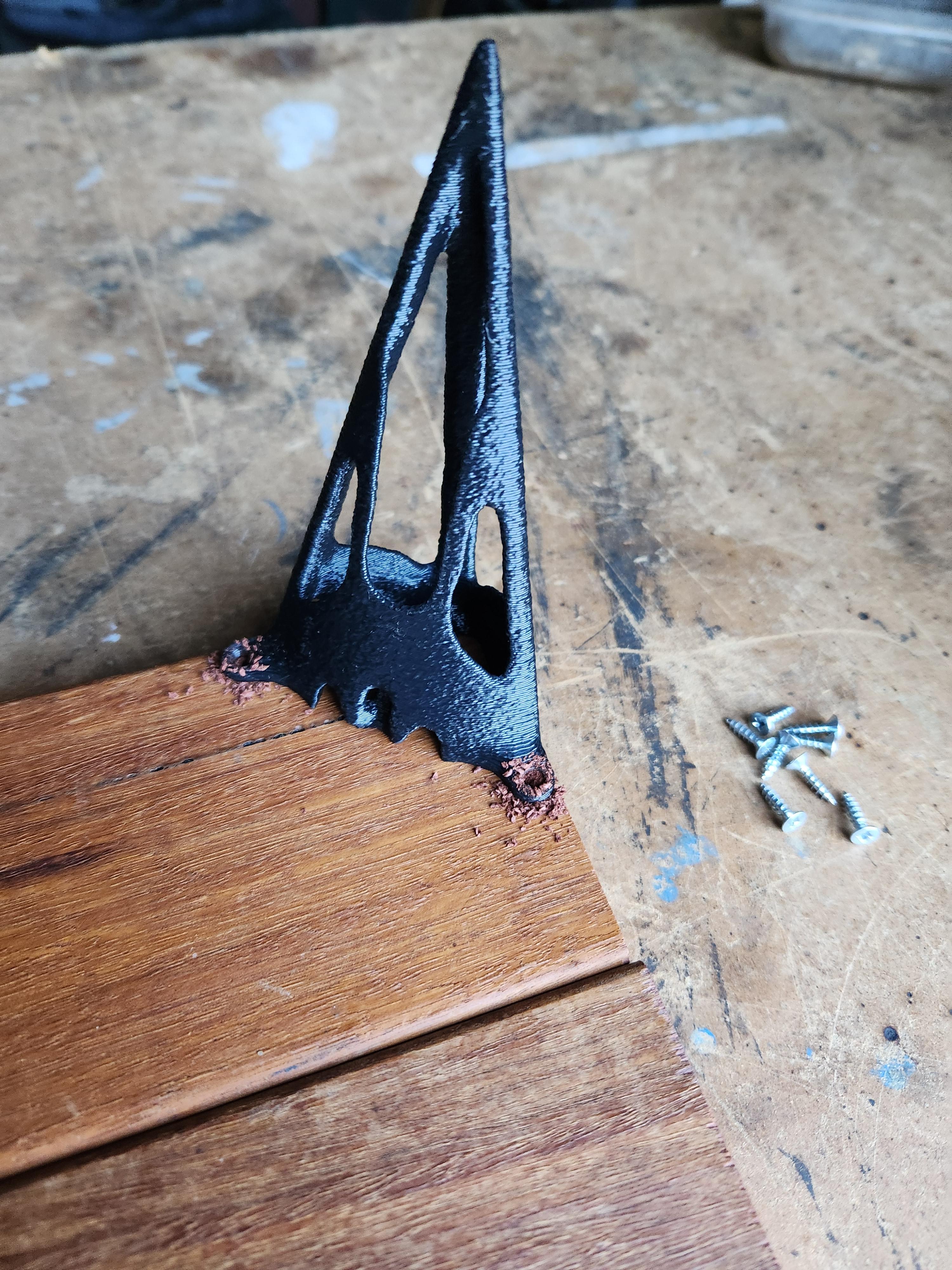
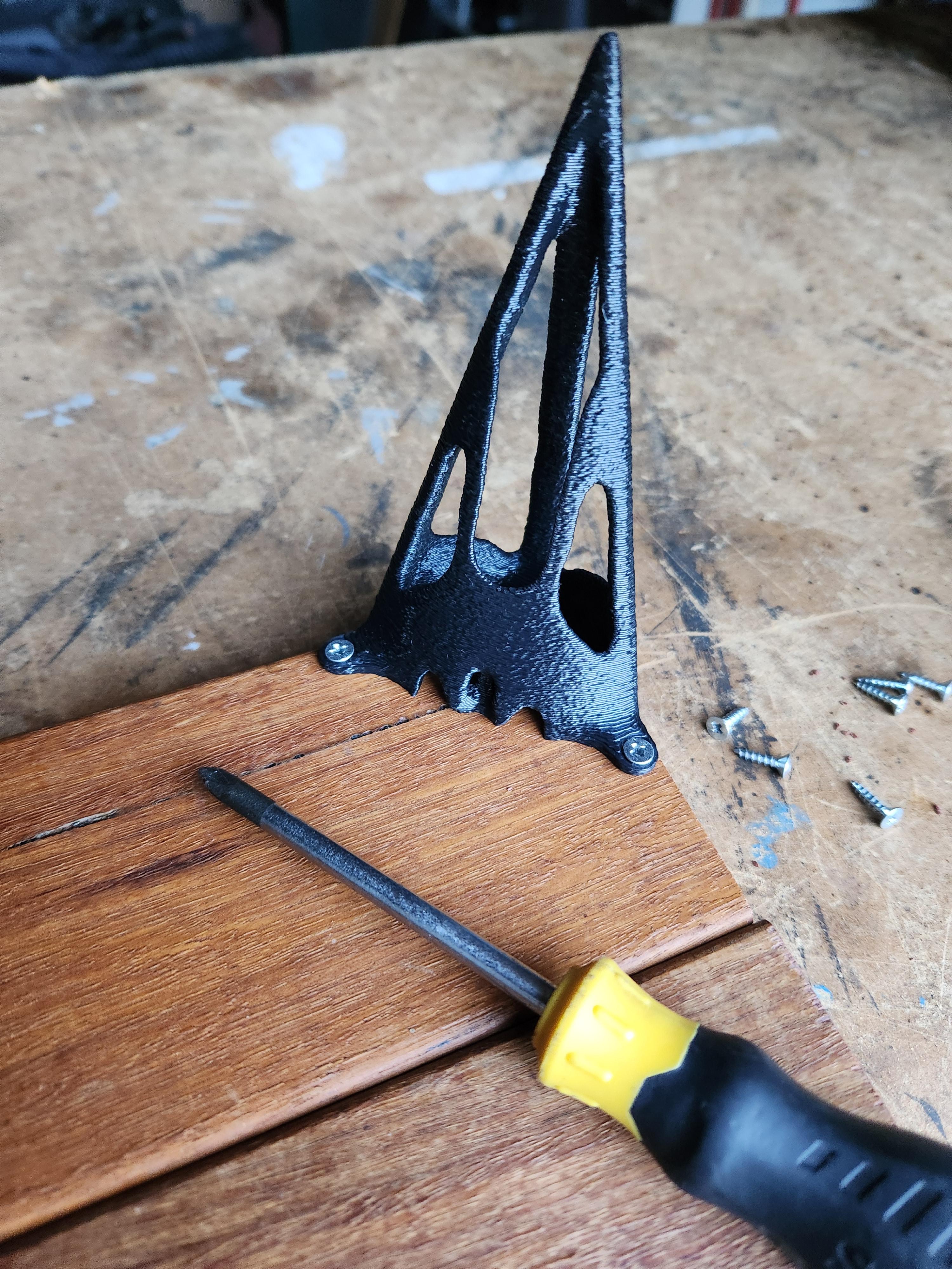
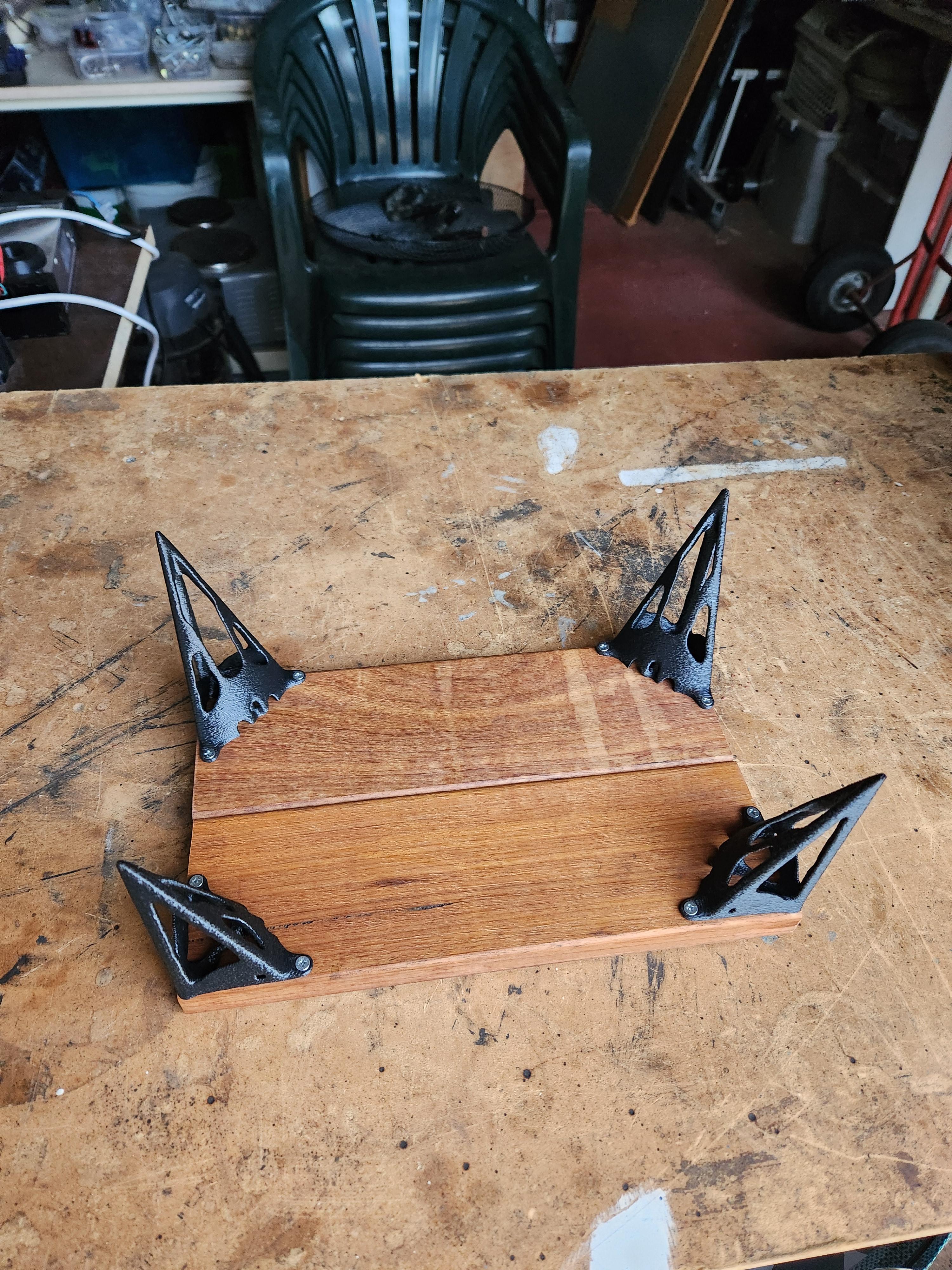
Once you have cut the wood down to size, it is time to do a dry fit. For this, you need to drill holes in the base of the planks and screw in the 3D-printed legs. This is an easy task as all you need to do is mark the location to drill the pilot holes by using a leg as a template. After screwing the legs in, clamp the 2 planks together to check everything is aligned.


If you are happy with the fit, add a bead of glue down each side and clamp them together to dry. You do not need much glue! Try to avoid as much squeeze-out as possible as it increases the amount of cleanup you need to do later. Once your glue has cured you can apply a finish if desired.


Results and Final Comments!
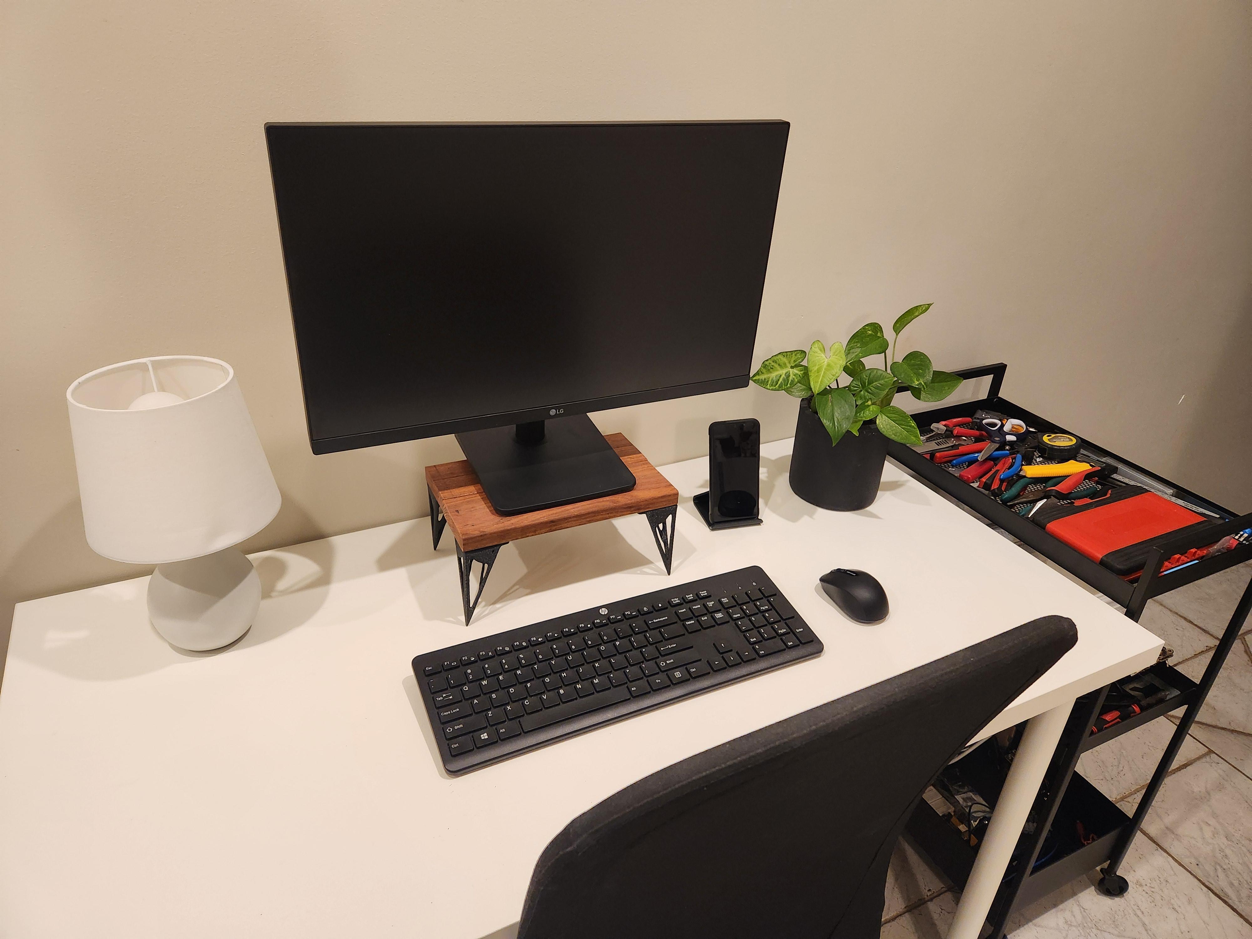
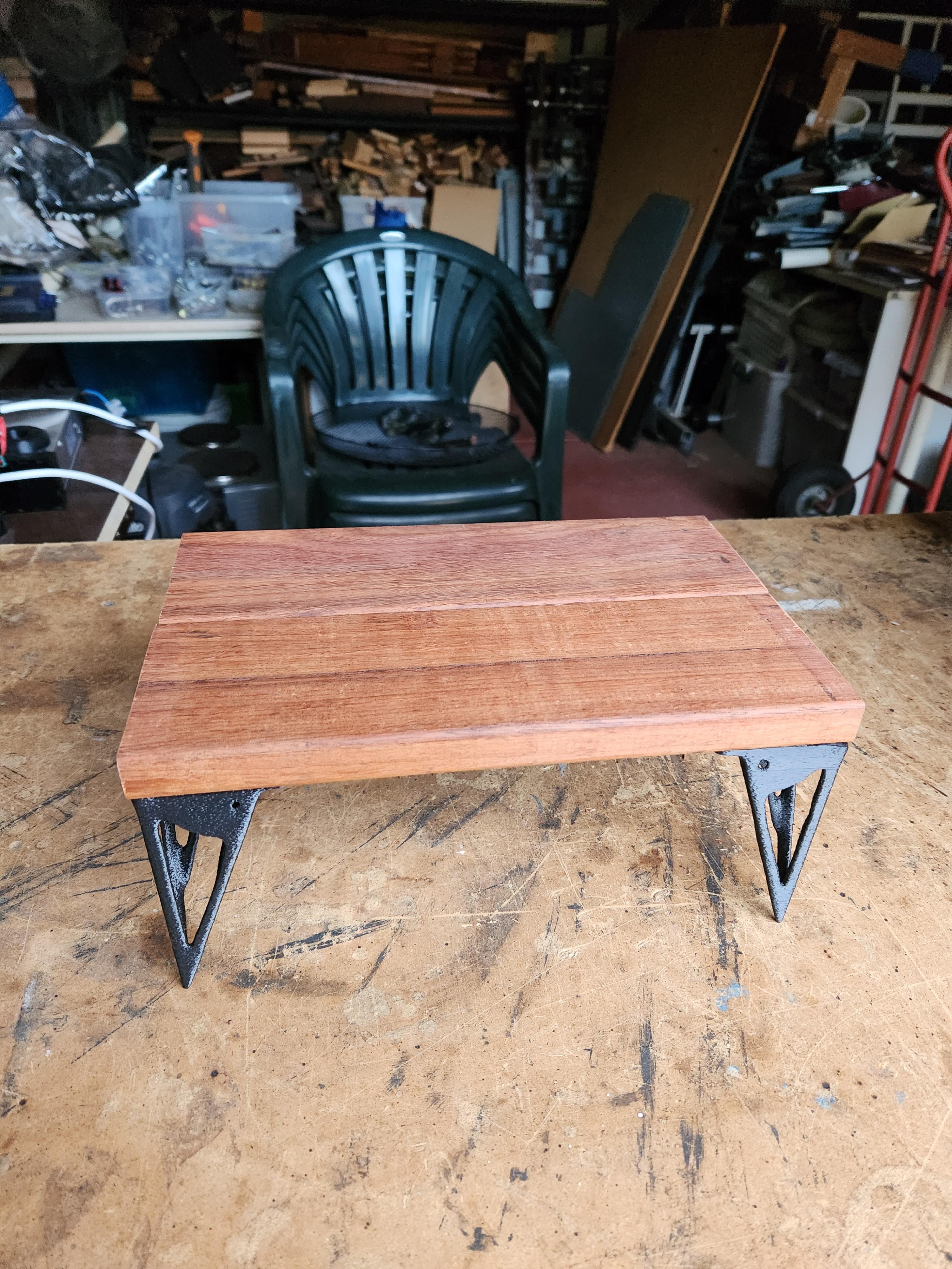
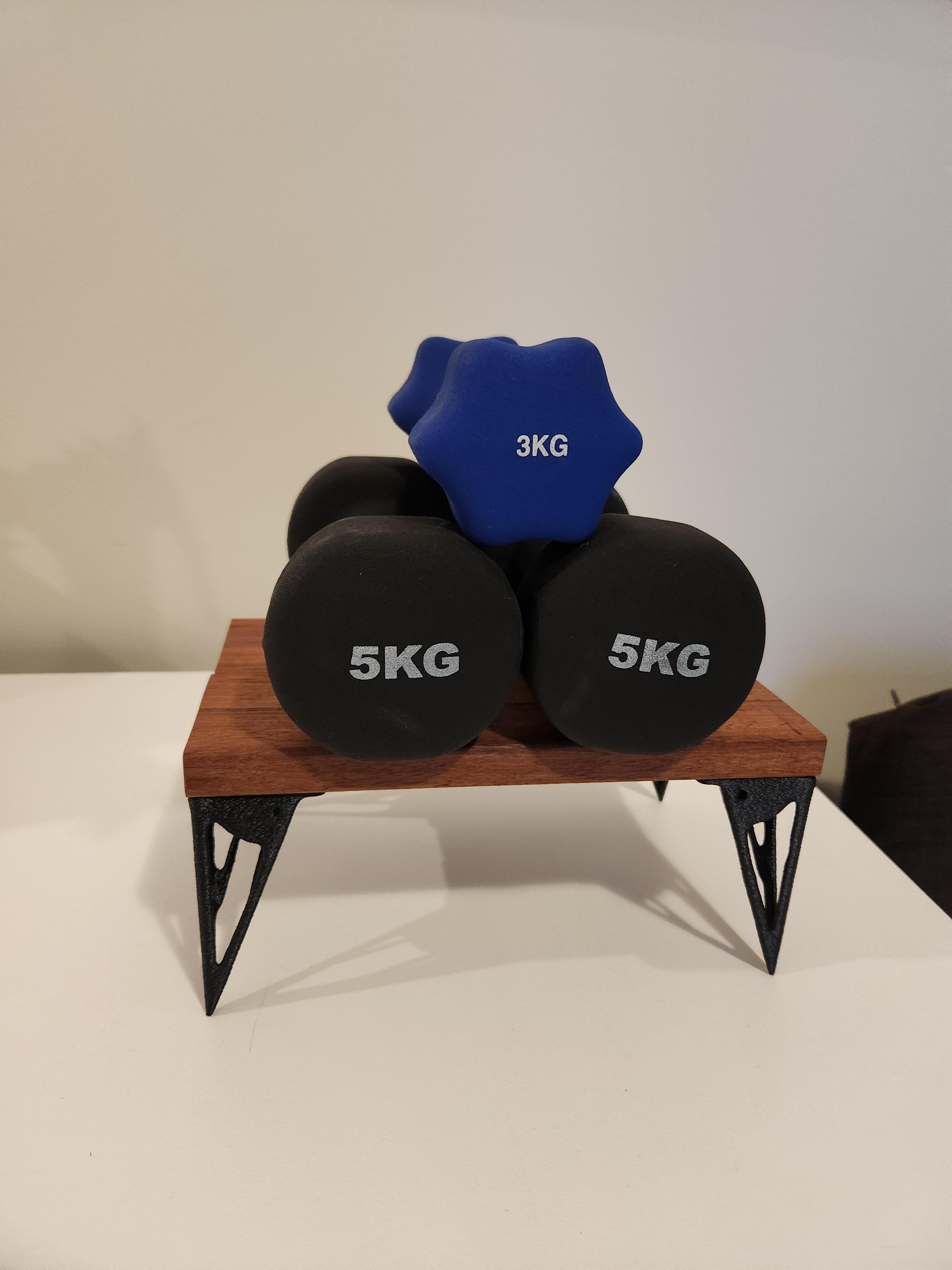
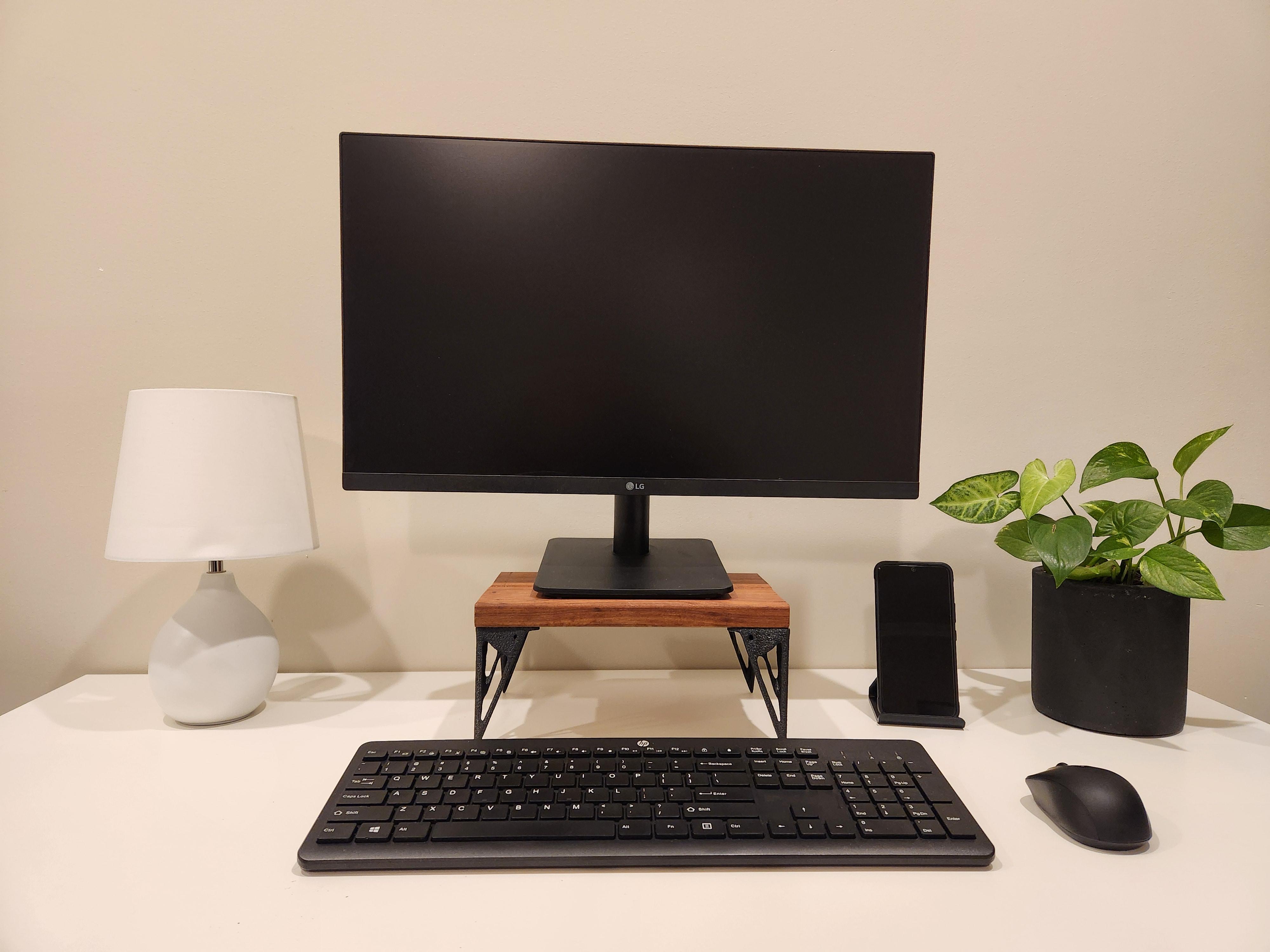
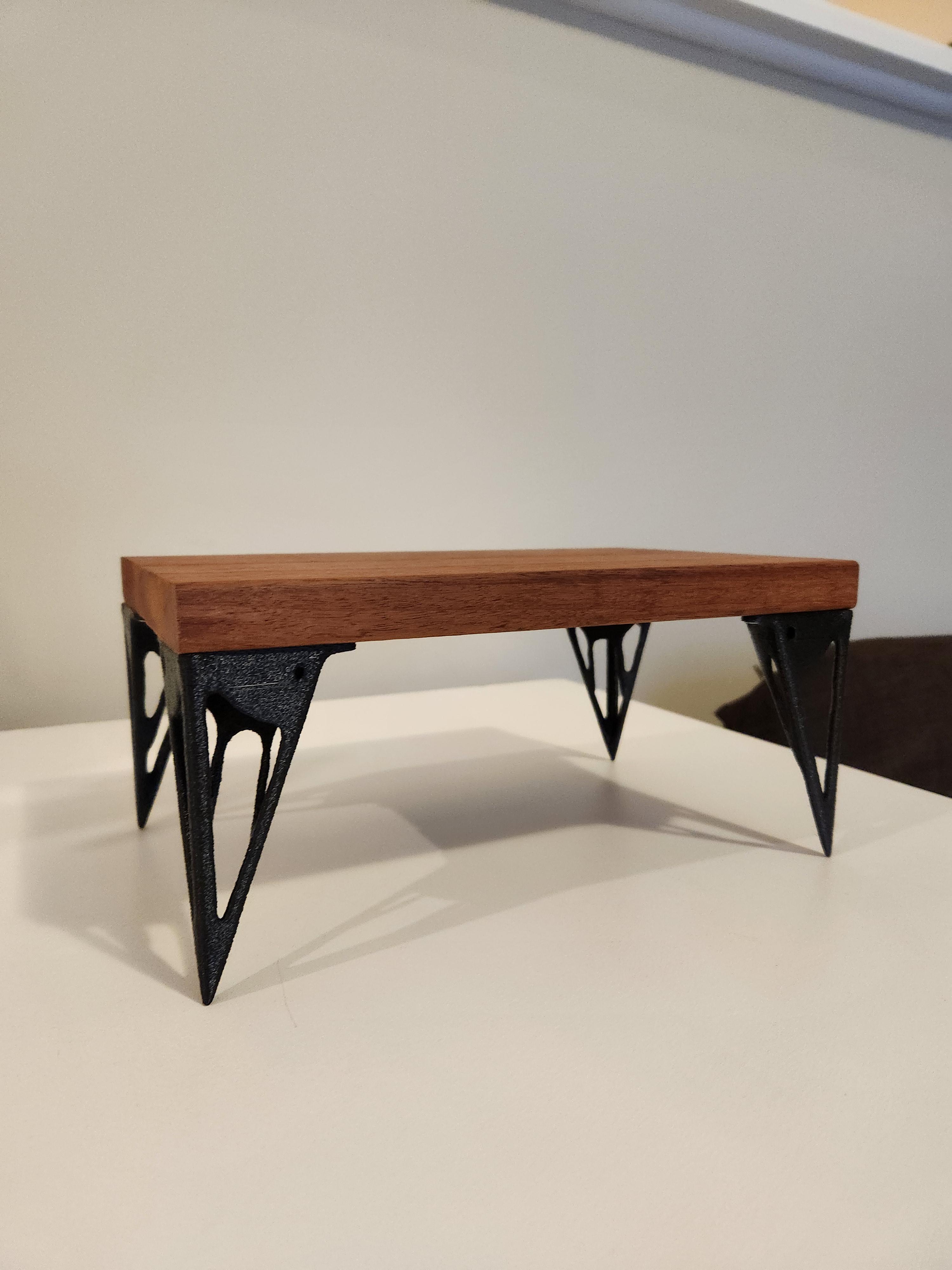
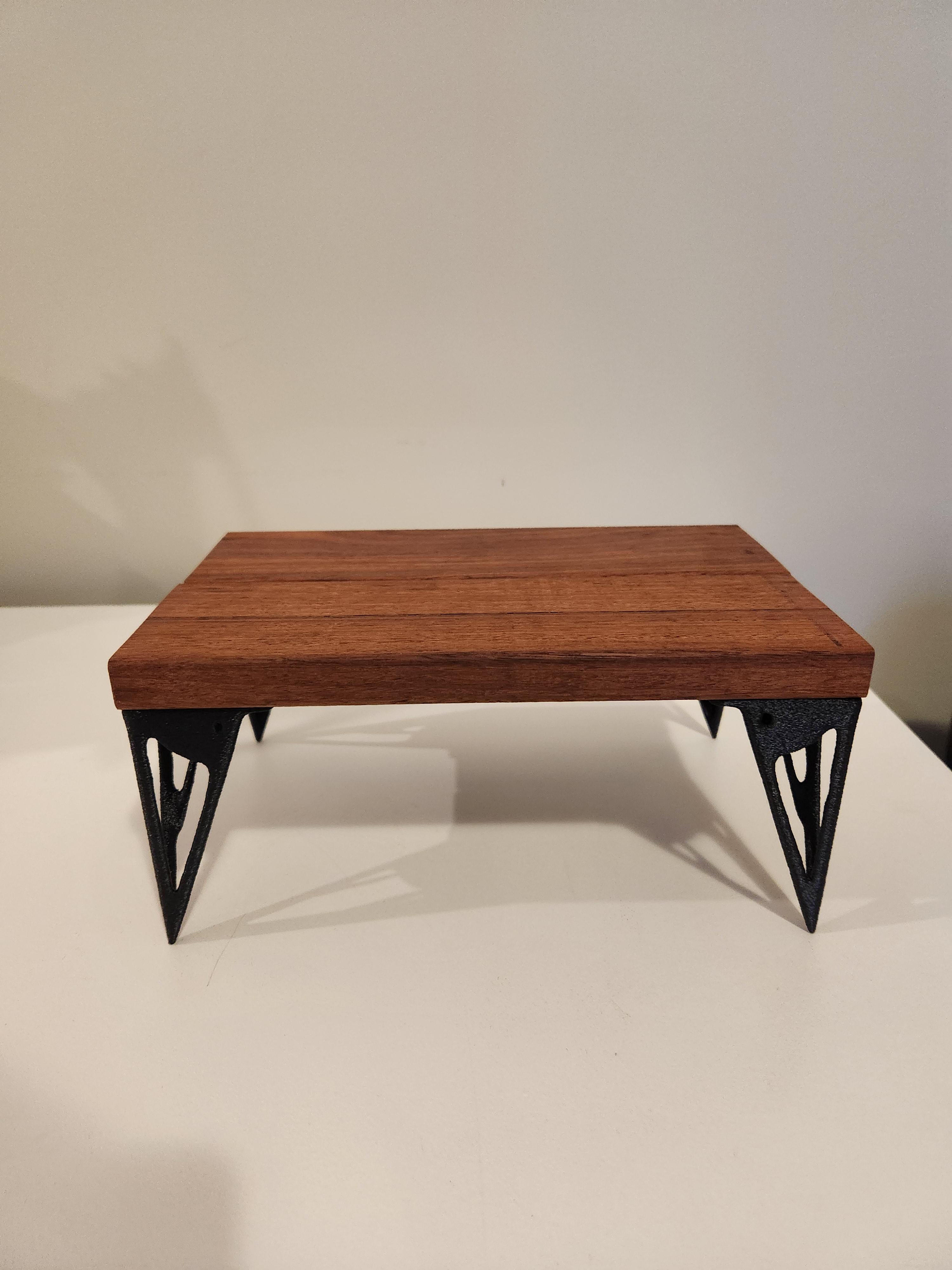
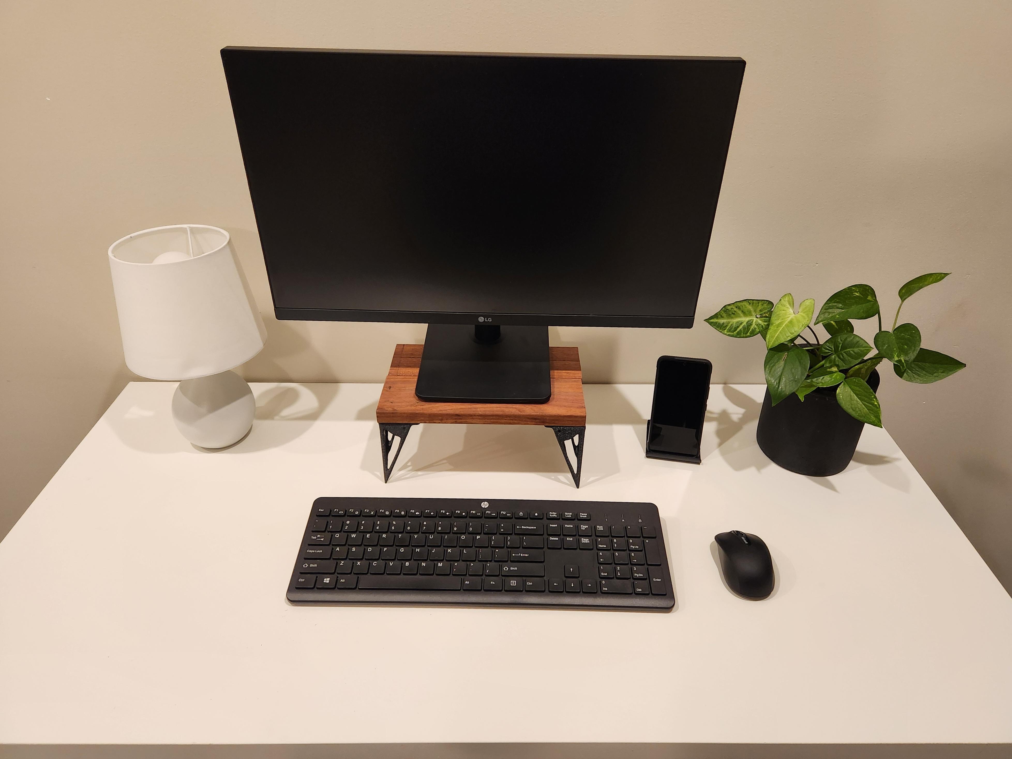
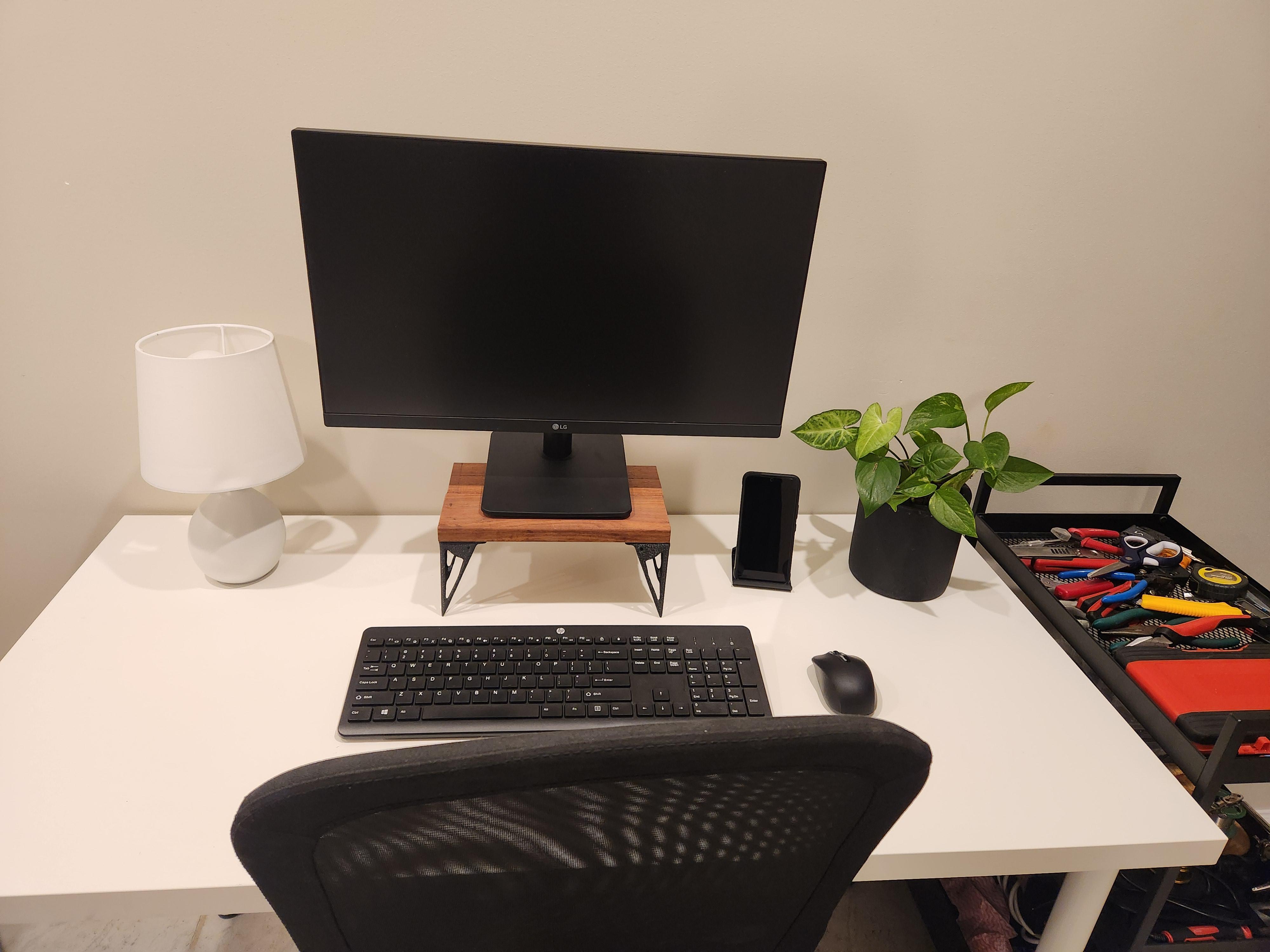
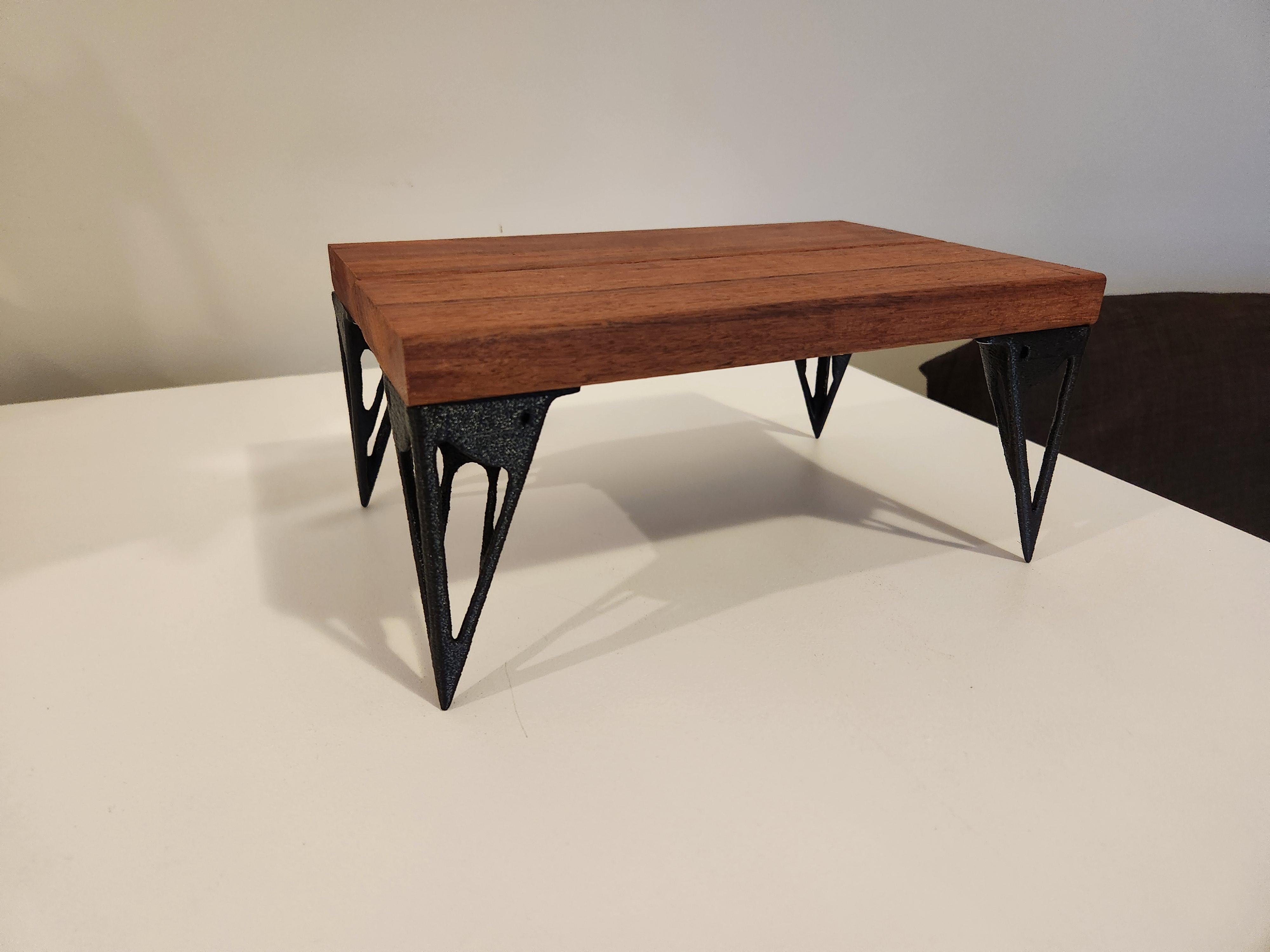
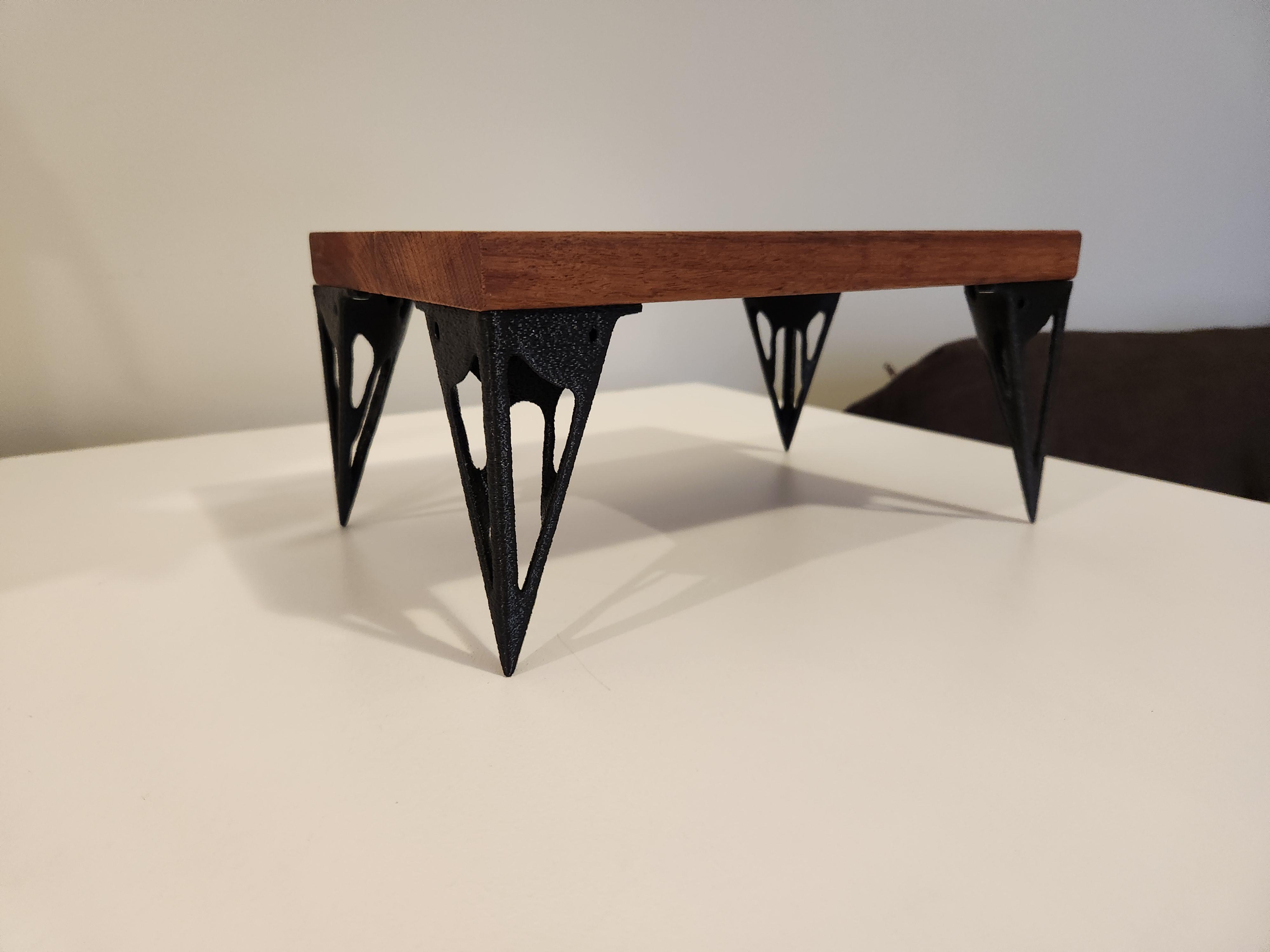
Overall I am super pleased with how the project turned out. The monitor stand comfortably held up 13kg (28 lbs) without any flexing or signs of cracking. This is a simple weekend project anyone of any skill level can undertake. I hope you learned something new about topology optimisation and the power of AI and other complex algorithms. As the world progresses more and more with technology, it offers so many new ways to design parts, such as merging the beauty of woodwork with the powers of 3D printing and Fusion360.
If you design something cool with topology optimisation or have any tips/questions, please comment, and I will get back to you!