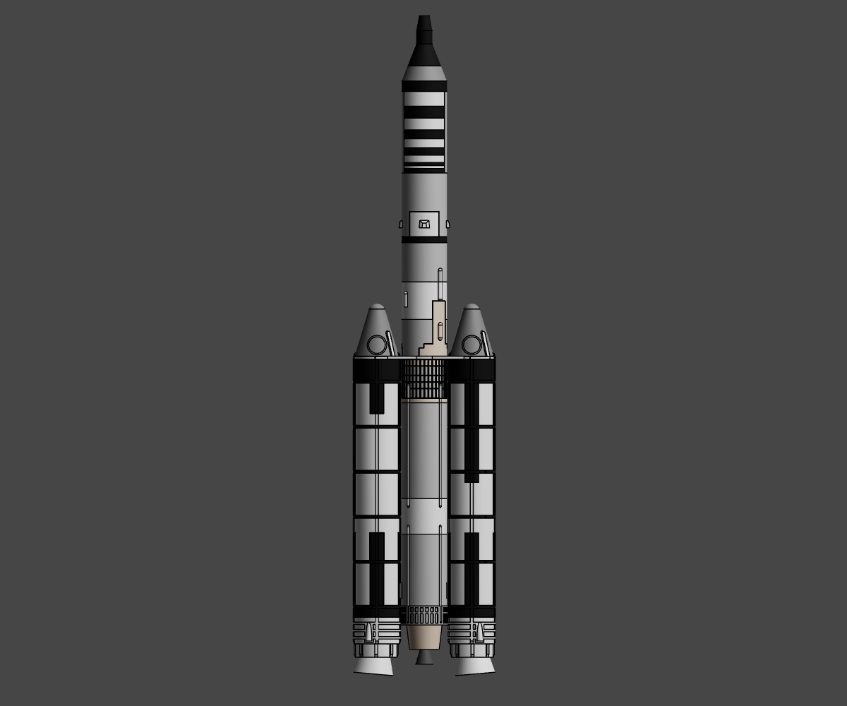
Titan 3C
.png)
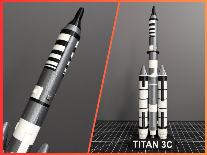
Here's a guide to printing my model of the Titan 3C
In this guide you will be guided through the correct positioning of the parts on the board, the settings in the Slicer and the assembly of the model.
Supplies
Tools
- 3D Printer
- 3D Slicer
- Glue
- Cutter
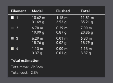
Filament
- White Filament (10m-32g)
- Black Filament (7m-20g)
- WarmWhite Filament (2m-4g)
- Metal Filament (7m-16g)
As stated on the model presentation page, you can use white or light orange filament instead of WarmWhite.
Fichier 3D
- 3D files of my Titan 3C model available on Printables
The Slice
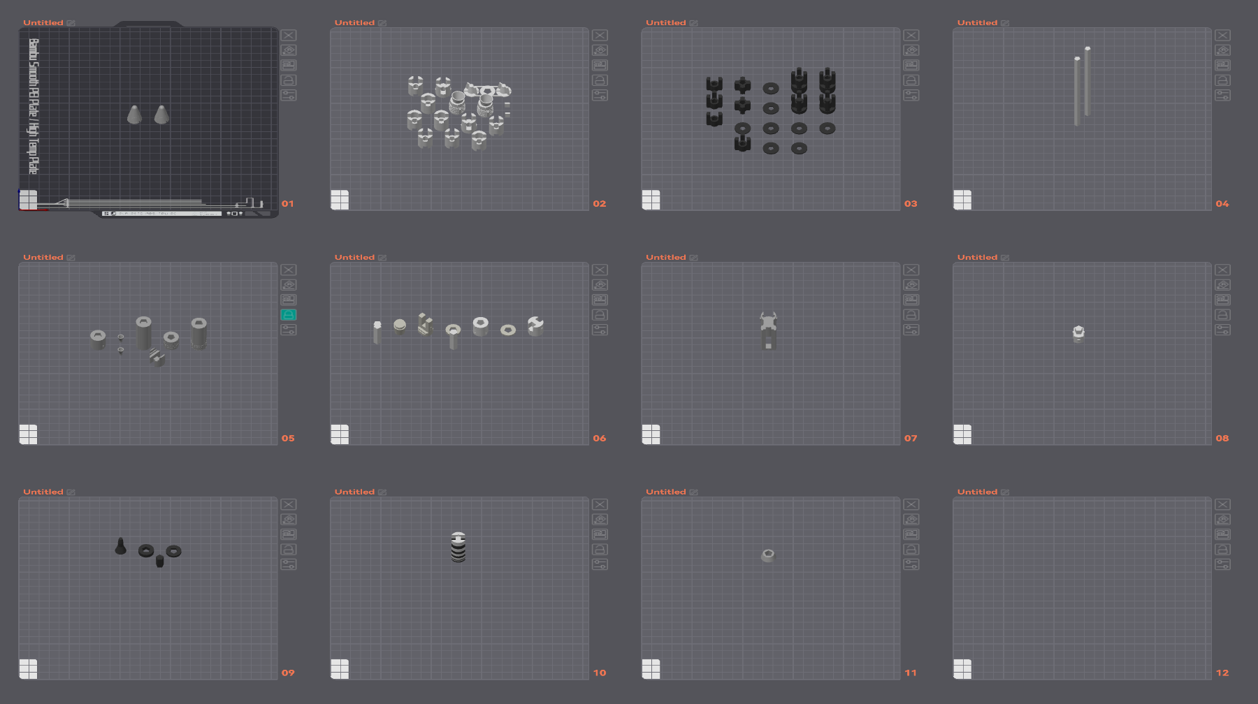
PRINCIPLE OF THE TABLE
I've divided the slice steps into 'blocks' corresponding to the stages of the rocket, but you can do the slice in any order you like.
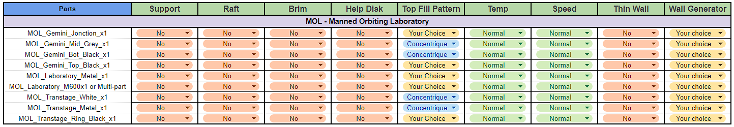
In each slice step you'll find a table with my advice on a number of parameters.
- The Supports will be in green in the slicer images, and I'll also put a note in the image.
- The Rafts, Brim and HelpDisk will be selected according to your usual settings in case your parts come unstuck.
- The Top Fill pattern is for a prettier result, but you can choose whatever you like.
- Temperature and Speed can be modified for certain parts, but your usual settings may also be valid.
- Thin walls can be activated on certain parts, but as with temperature and speed, your usual settings may also be valid.
There's also a picture for the ideal placement of each piece. I only placed one piece of each, but it can be repeated for the quantity requested.
I also added annotations to some of the images.
IMPORTANT
For "Jonction" parts, I advise you to print as tightly as possible, adding 1% by 1% to the scale to ensure perfect assembly.
Slice MOL - Manned Orbiting Laboratory
Before starting, you must choose between two versions
- Laboratory_M600
- 🔼Multi Color Print (AMS/M600/MMU/Color Change)
- 🔼Better final result
- 🔼Less assembly
- 🔽Separate parts in the Slicer
- Laboratory (Multi-Part)
- 🔼No multi Color
- 🔼No handling in the slicer
- 🔽More parts to print and assemble
There are no specific parameters for this stage.
Slice 3A-1
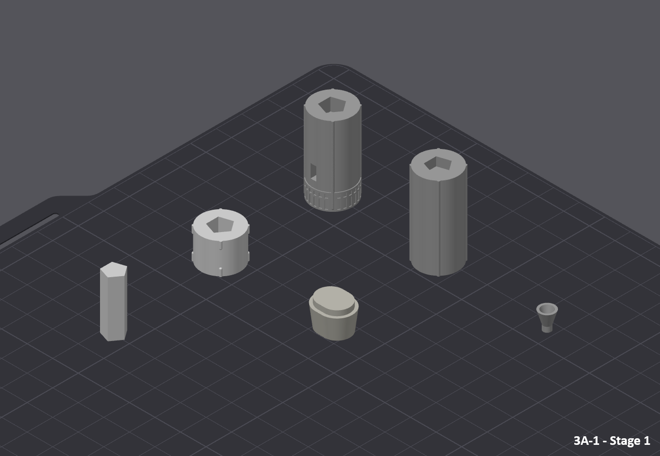
There are no specific parameters for this stage.
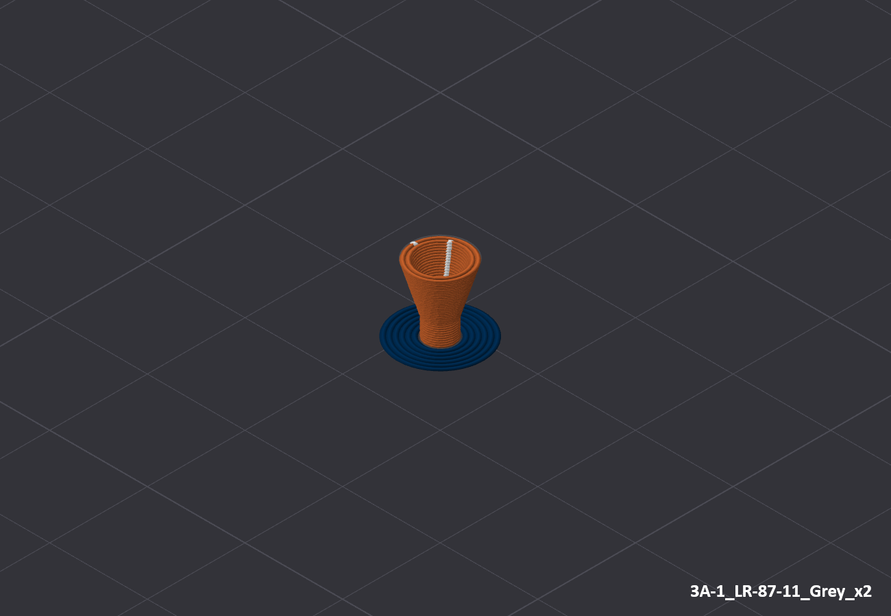
For parts"3A-1_LR-87-11_Grey_x2" and "3A-1_Jonction_x2" you can use a brim to help hold them in place.
Slice - Interstage

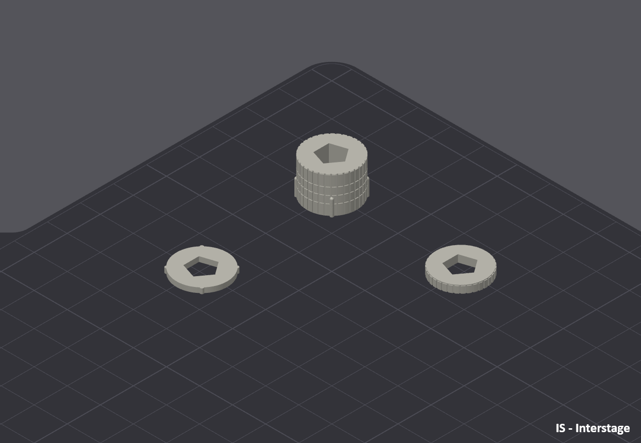
There are no specific parameters for this stage.
Slice 3A-2
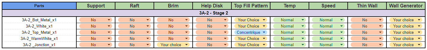
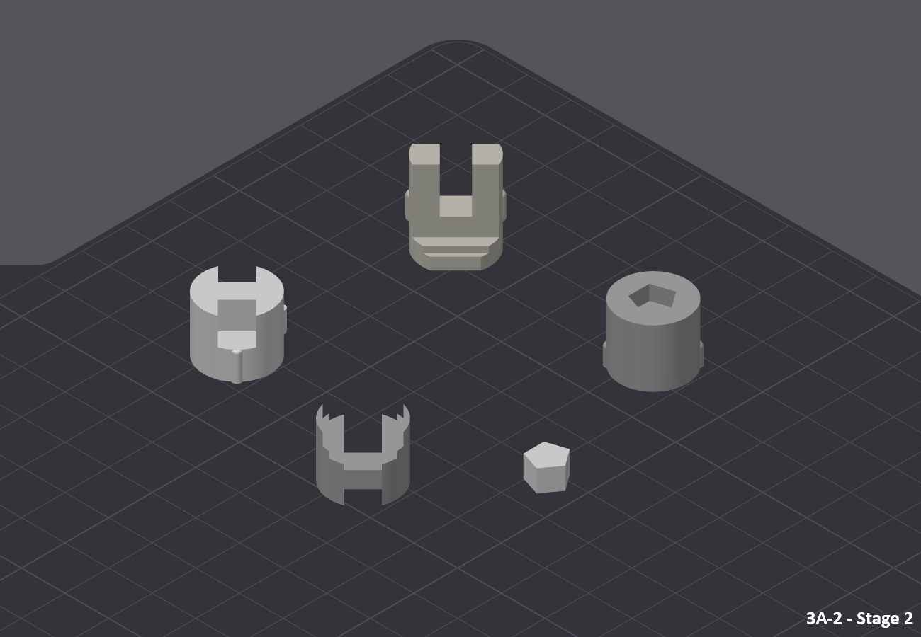
There are no specific parameters for this stage.
For parts "3A-2_Jonction_x1" you can use a brim to help hold them in place.
Slice - SRM

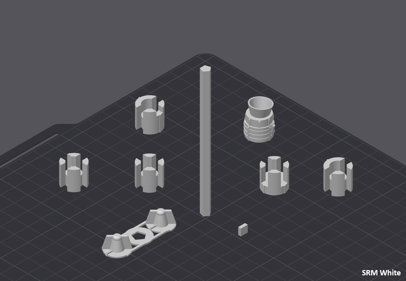
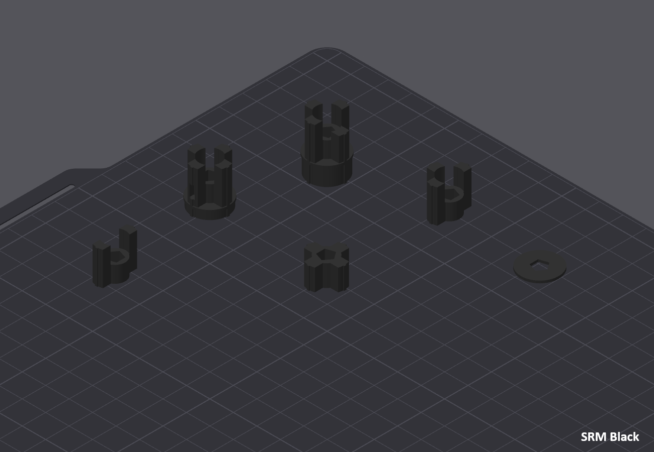
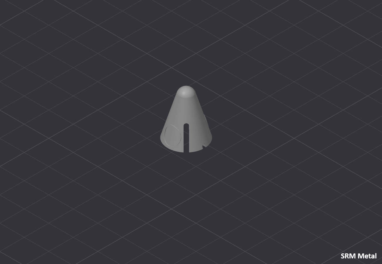
There are no specific parameters for boosters.
For parts"SRM_Jonction_Rod_x2" and "SRM_Jonction_Bot_White_x2" you can use a brim to help hold them in place.
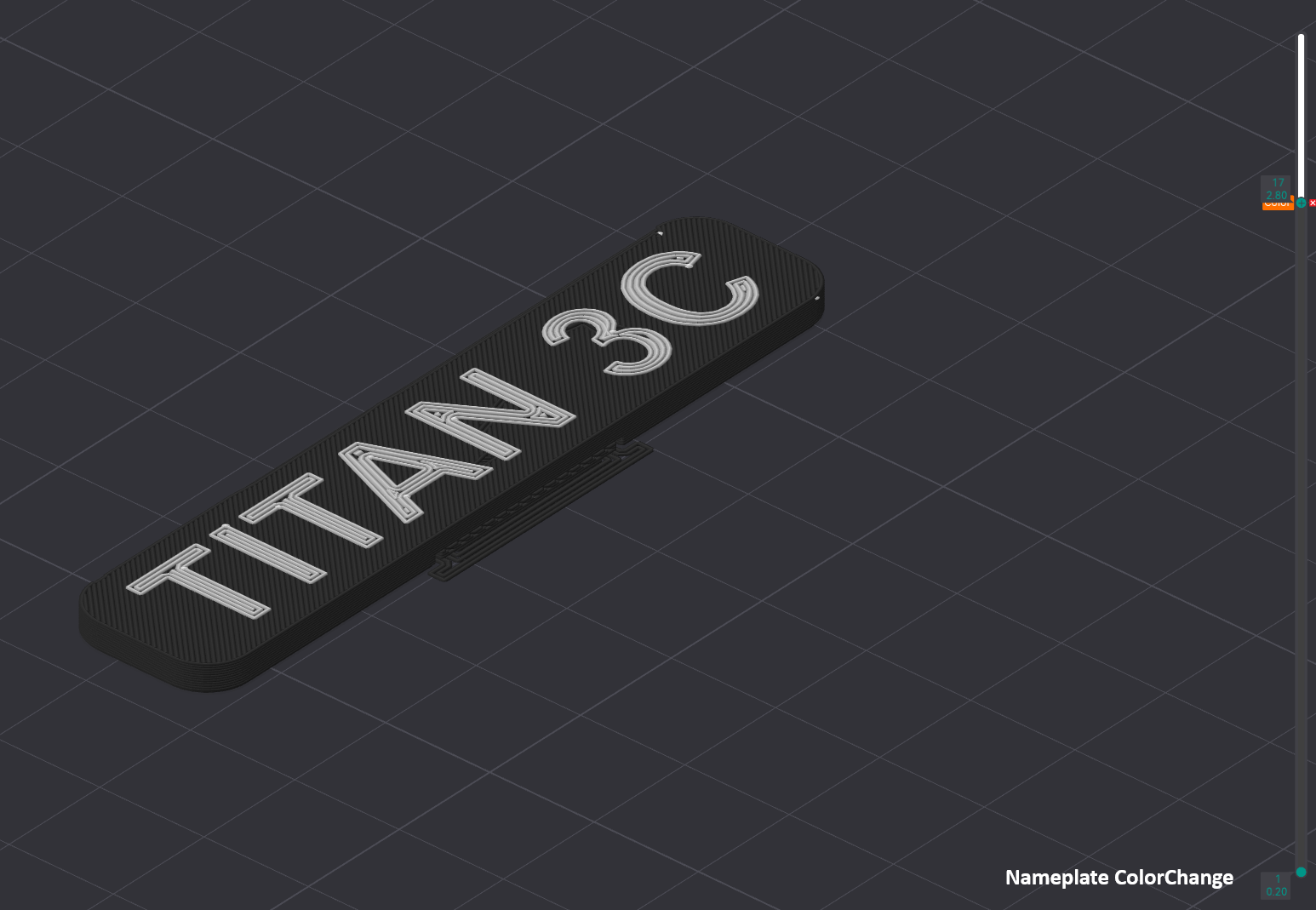
Slice - Stand


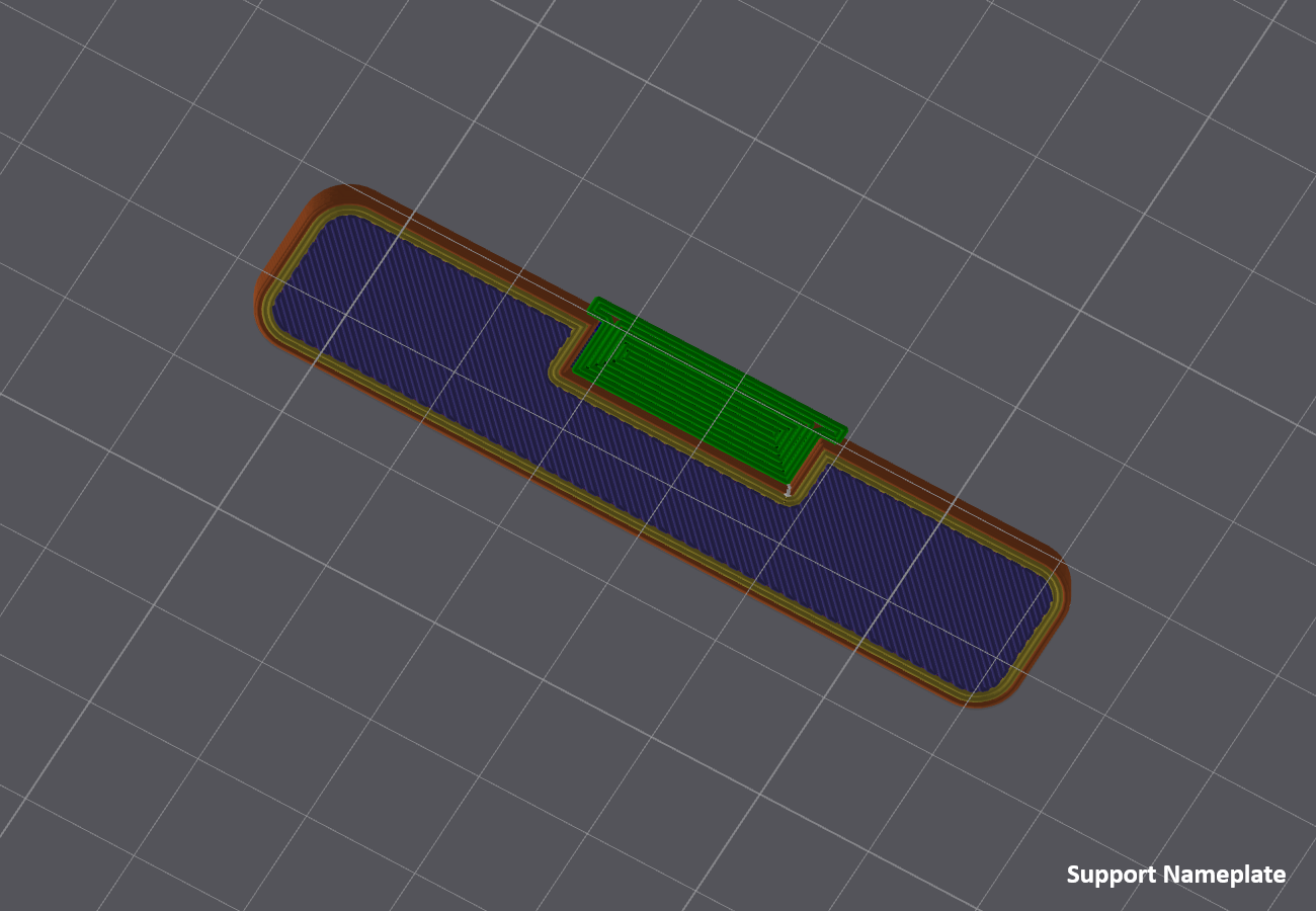
Before starting, you must choose between two versions
- Nameplate_M600
- 🔼Multi Color Print (AMS/M600/MMU/Color Change)
- 🔼Better final result
- 🔼Less assembly
- 🔽Paint parts in the Slicer
- Nameplate (Multi-part)
- 🔼No multi Color
- 🔼No handling in the slicer
- 🔽More parts to print and assemble
There are no specific parameters for the stand.
Assembly
Once the supports have been removed, you can begin assembly.
The assembly steps will also be divided by 'blocks', this time I advise you to follow the direction of the guide.
At the bottom right of each image there will be a step code, the letter for the Block and the number for the step, for example A1 for step 1 of Block A.
3A-1
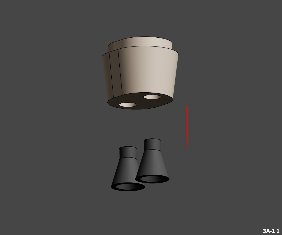
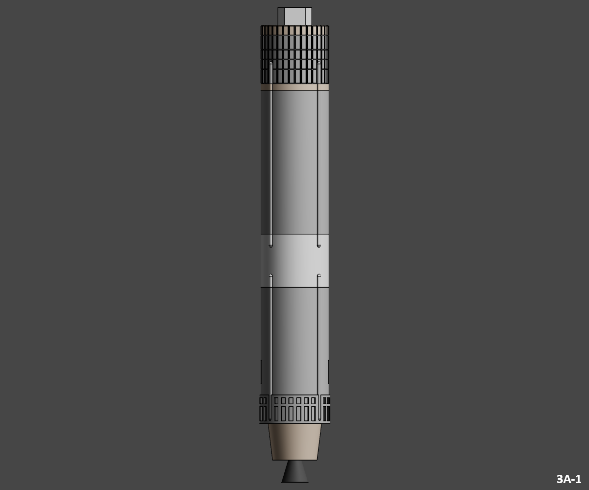
3A-1 1
- Glue "3A-1_LR-87-11_Grey" motors in "3A-1_Engine_Section_WarmWhite" motor block.
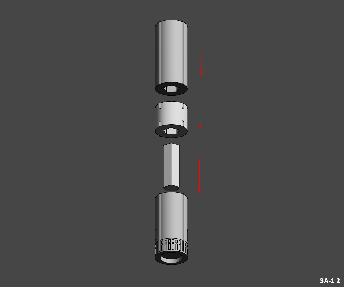
3A-1 2
- Glue the first junction piece "3A-1_Jonction" into the lower tank "3A-1_Bot_Metal".
- Then glue "3A-1_Mid_White" into the already assembled junction.
- Glue the top tank "3A-1_Top_Metal" on top.
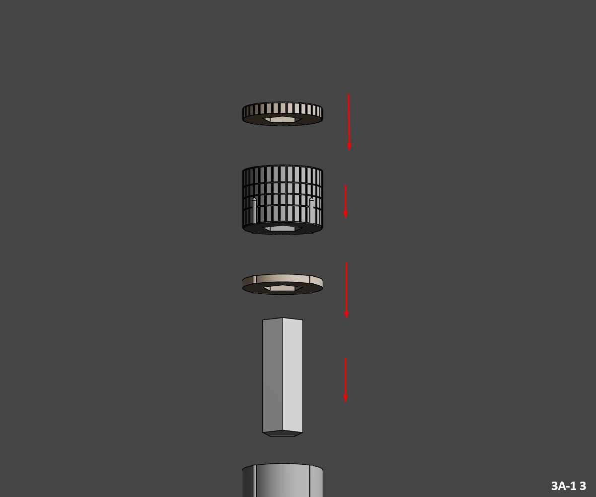
3A-1 3
- Glue second joint piece "3A-1_Jonction" into top tank "3A-1_Top_Metal".
- Then glue the first interstage part "IS_Bot_WarmWhite" into the junction already assembled.
- Glue the "IS_Mid_Metal" piece on top, followed by the "IS_Top_WarmWhite" piece.
Congratulations, you've finished assembling the First Stage, now you can assemble the Second Stage.
3A-2
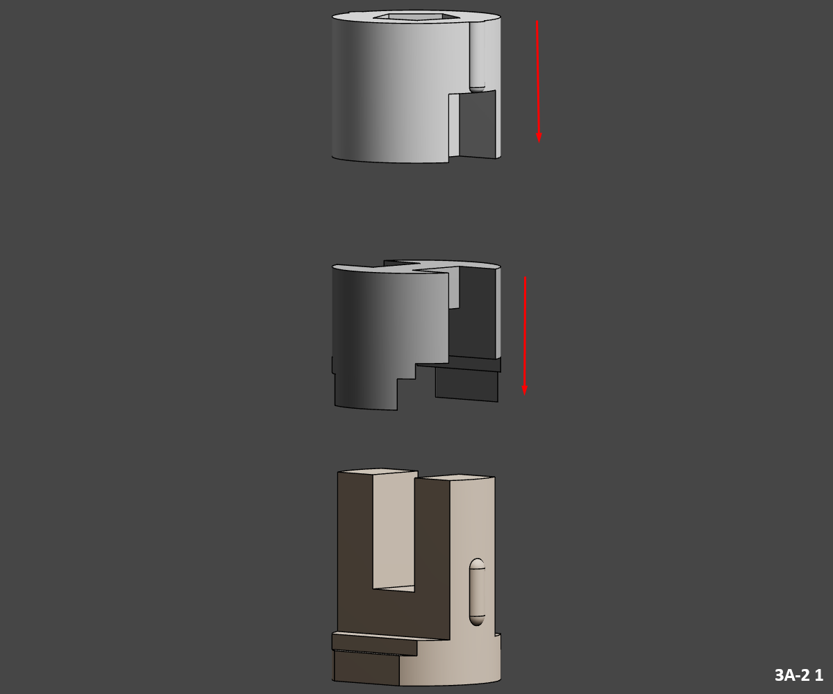
3A-2 1
- Glue part "3A-2_Bot_Metal" into part "3A-2_WarmWhite".
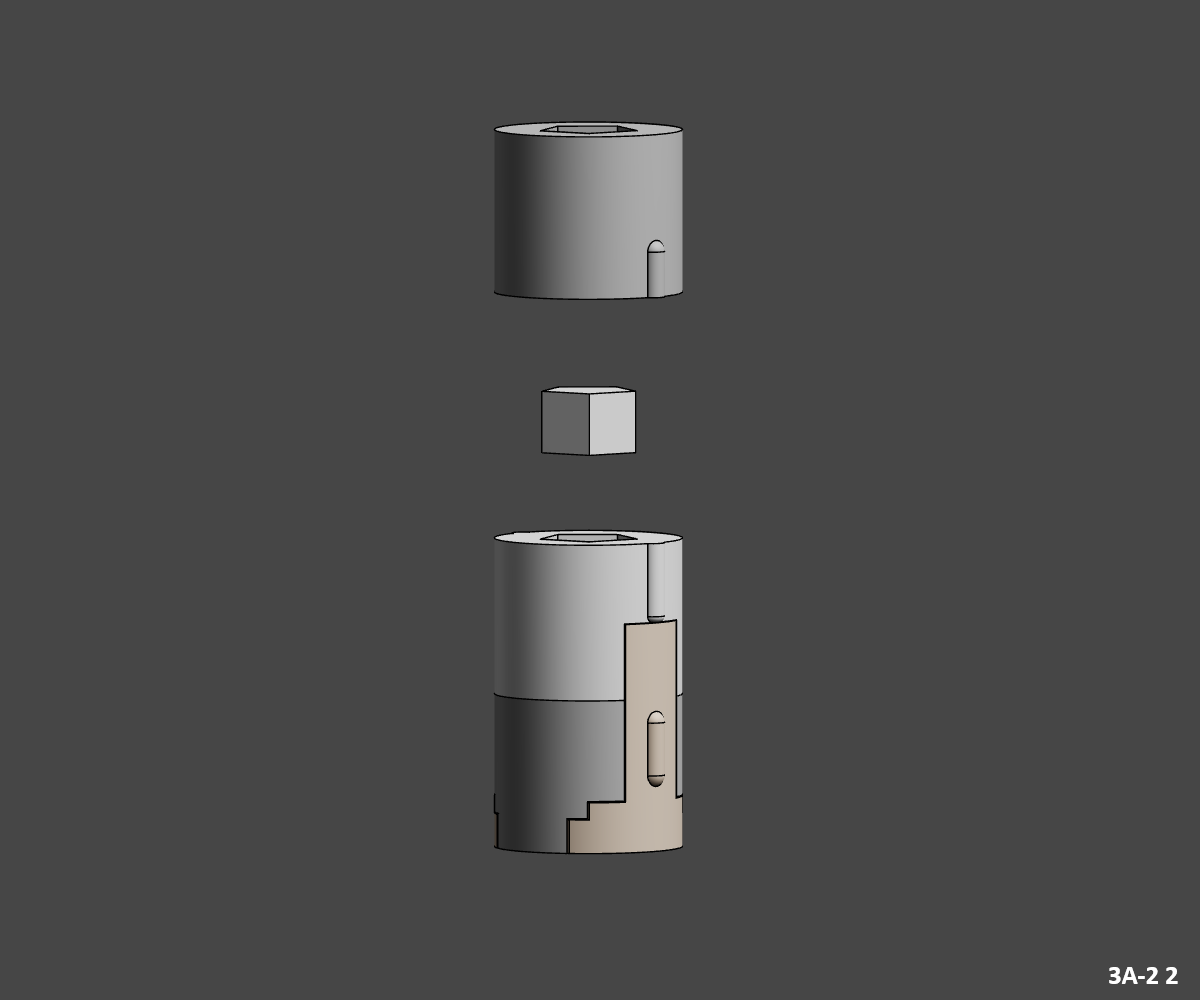
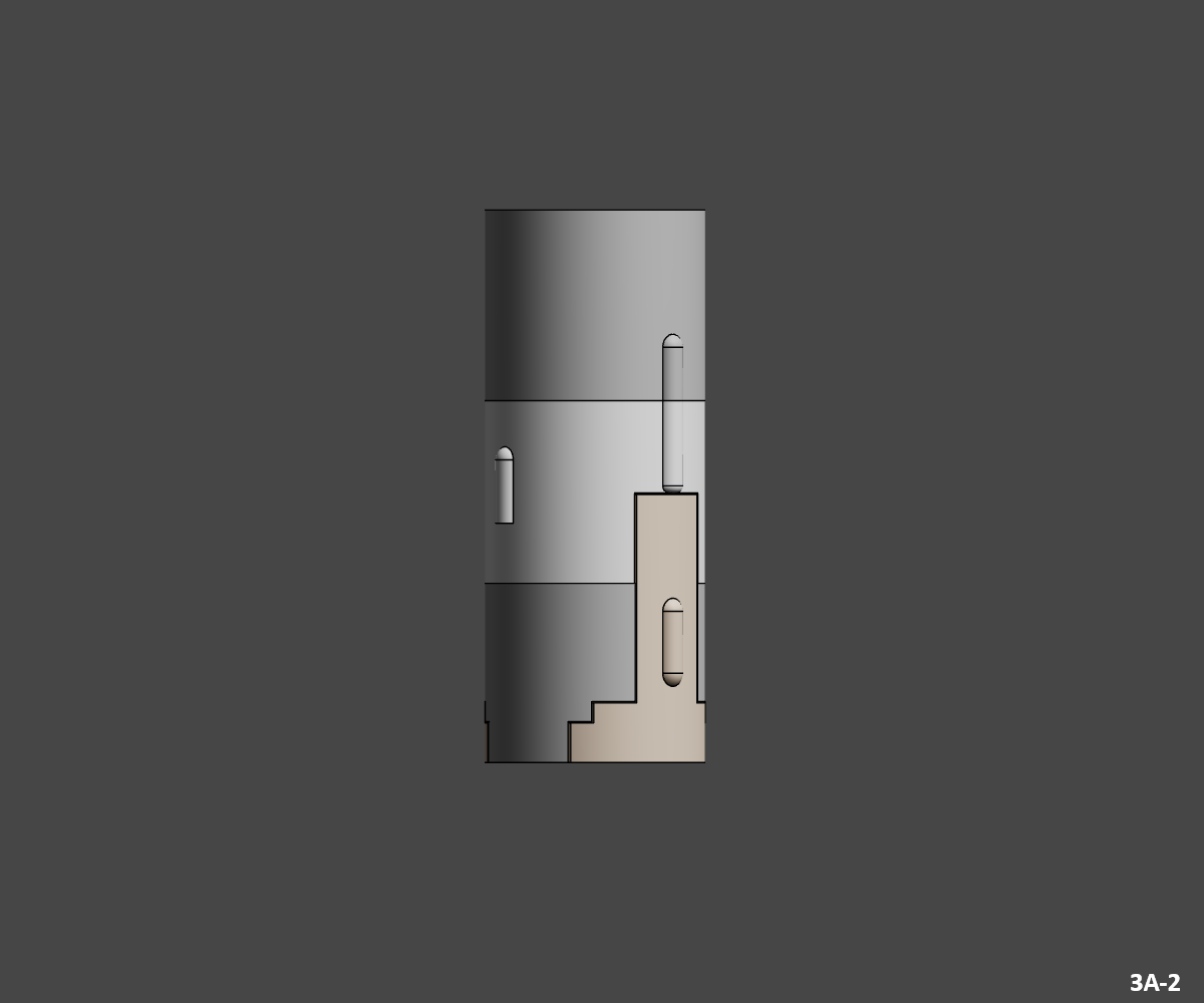
3A-2 2
- Glue the "3A-2 _Junction" joint into the assembly.
- Then glue the "3A-2_Top_Metal" part on top.
Congratulations, you've finished assembling the Second Stage, now you can assemble the MOL.
MOL
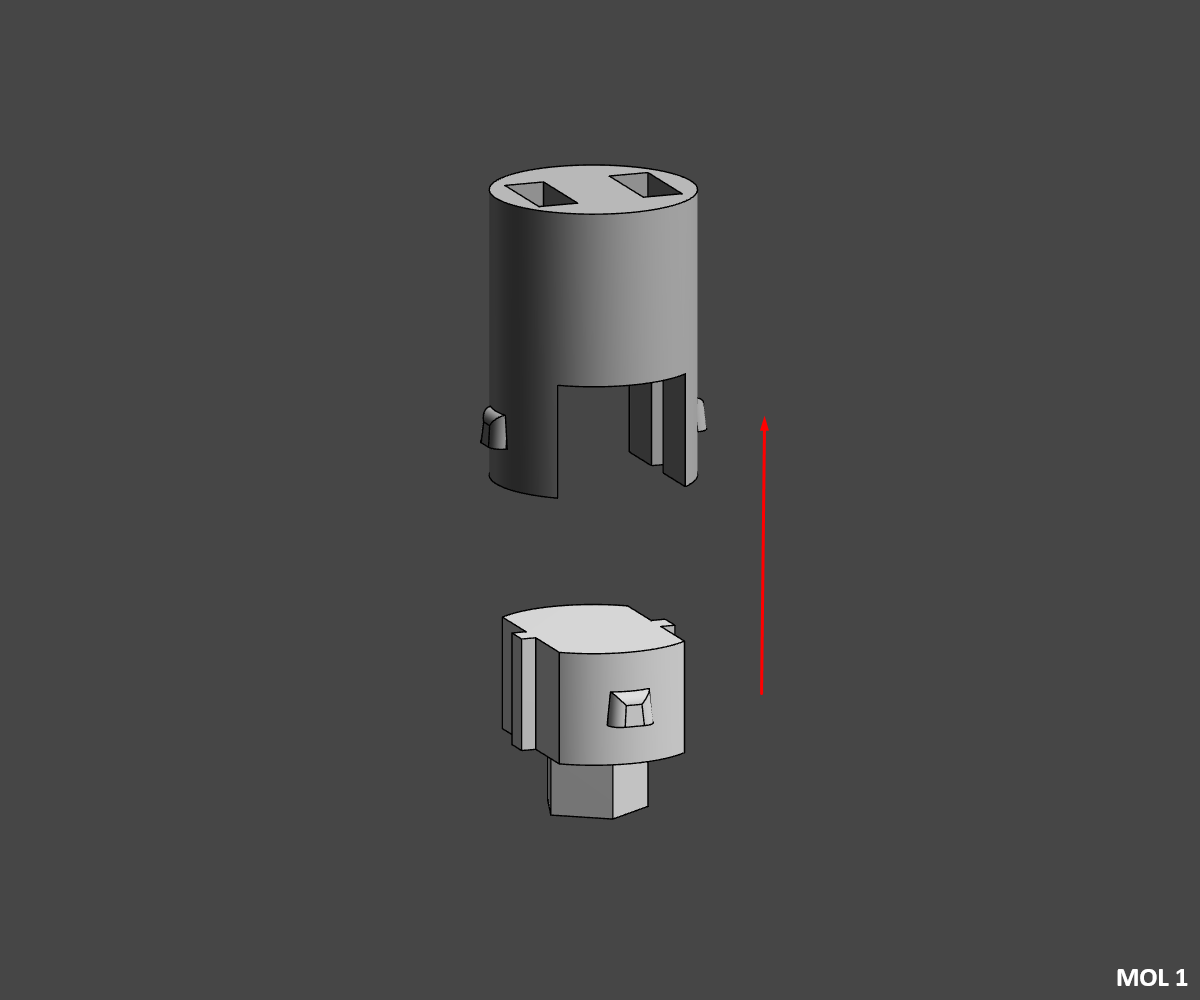
MOL 1
- Glue part "MOL_Transtage_White" into part "MOL_Transtage_Metal".
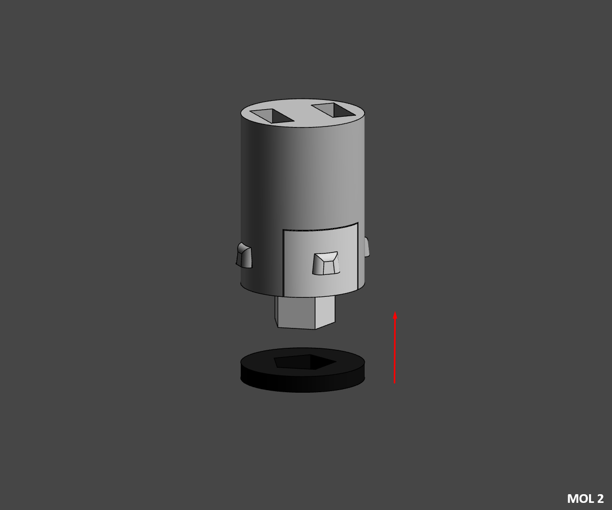
MOL 2
- Glue the "MOL_Transtage_Ring_Black" part into the assembly.
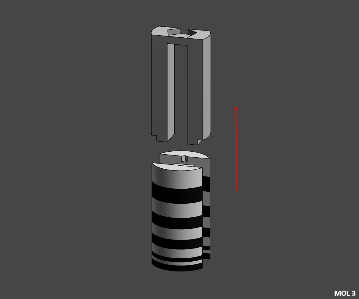
MOL 3
⚠️ if you've chosen the MOL_Laboratory multipart option, you'll need to assemble it in this direction 10W-9B-8W-7B-6W-5B-4W-3B-2W-1B
⚠️ Pay attention to the assembly direction (with the small point on the "MOL_Laboratory_10_White" part )
- Slide and glue the "MOL_Laboratory" parts into the "MOL_Laboratory_Metal" part.
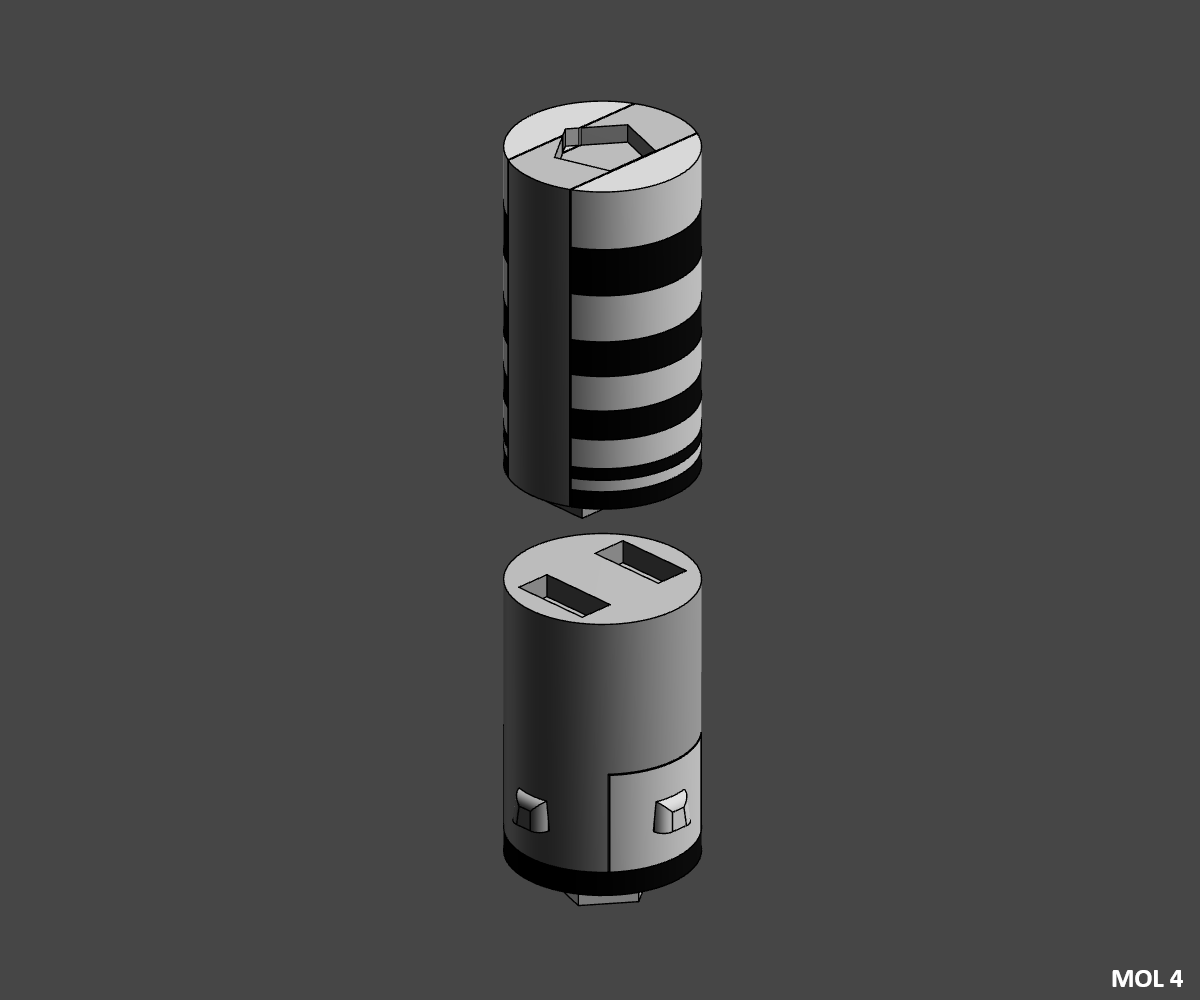
MOL 4
⚠️ Pay attention to the direction of assembly (the top and bottom hexagons are not in the same direction).
- Glue the two assemblies together.
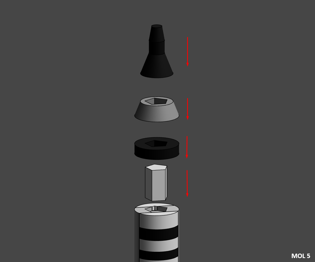
MOL 5
- Glue the "MOL_Gemini_Jonction" junction piece to the previous assembly.
- Then glue "MOL_Gemini_Bot_Black" on top.
- Then glue the "MOL_Gemini_Mid_Grey" piece on top.
- Finish by gluing the "MOL_Gemini_Top_Black" piece .
Congratulations, you've finished assembling the MOL, now you can assemble the two SRM.
SRM
⚠️ This step must be performed twice, once for each booster.
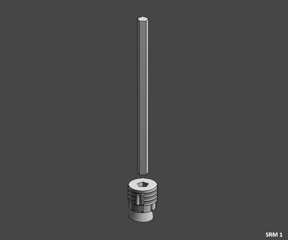
SRM 1
- Glue the "SRM_Jonction_Rod" rod in the "SRM_Engine_White" motor .
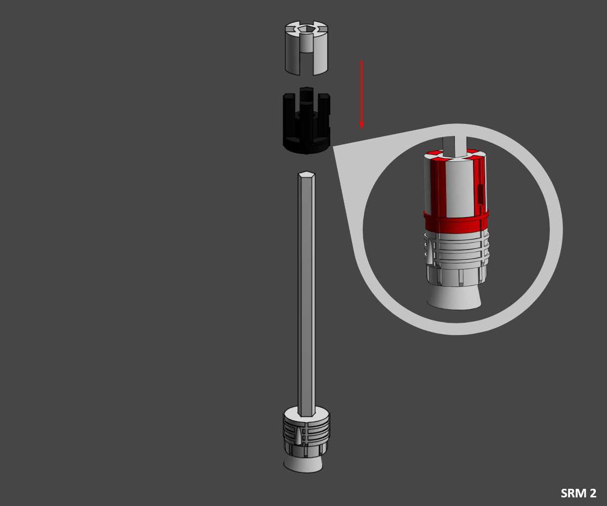
SRM 2
⚠️ Be careful to align the hole in the red part with the longer side of the motor.
- Slide and glue the two pieces of Section 5 "SRM_S5_Black" and "SRM_S5_White" onto the jonction rod.
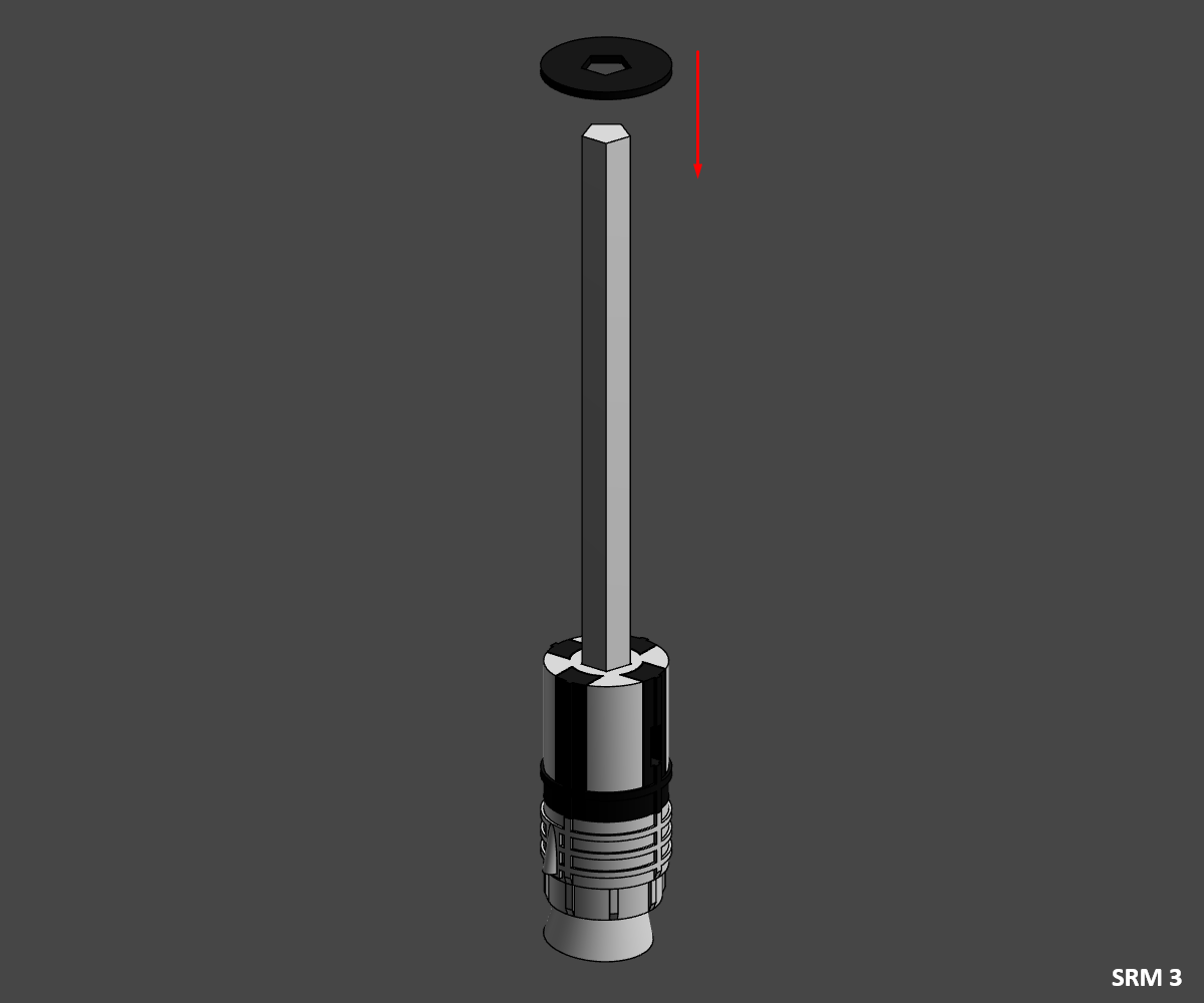
SRM 3
- Slide and glue an "SRM_Ring_Black" ring onto the jonction rod.
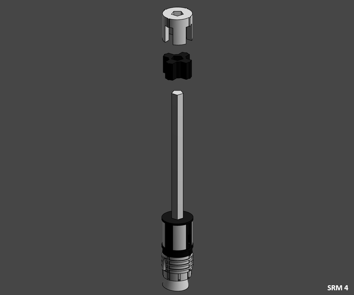
SRM 4
⚠️ Pay close attention to alignment, as shown in the pictures.
- Slide and glue the two pieces from Section 4 "SRM_S4_Black" and "SRM_S4_White" onto the jonction rod.
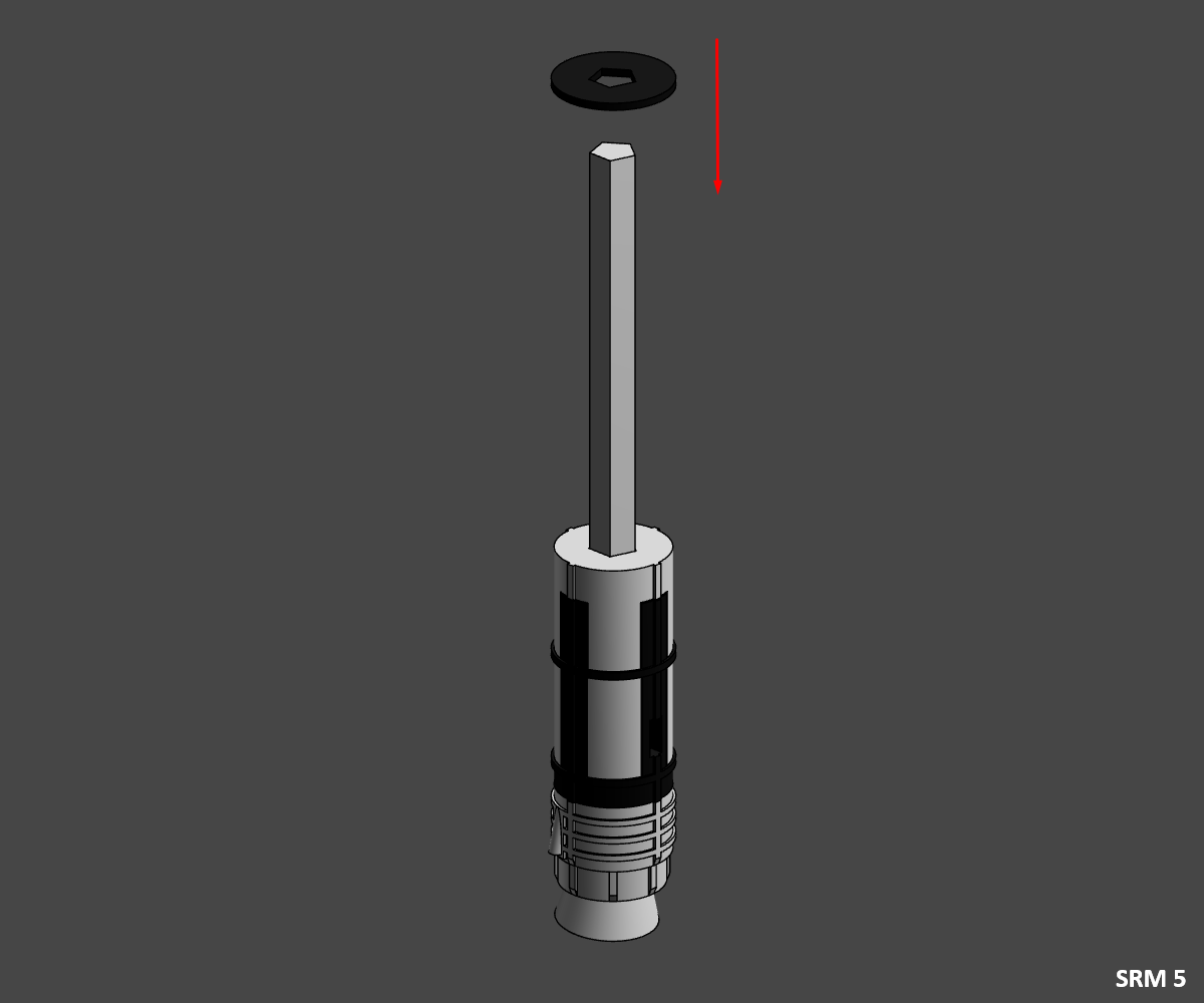
SRM 5
- Slide and glue an "SRM_Ring_Black" ring onto the jonction rod.
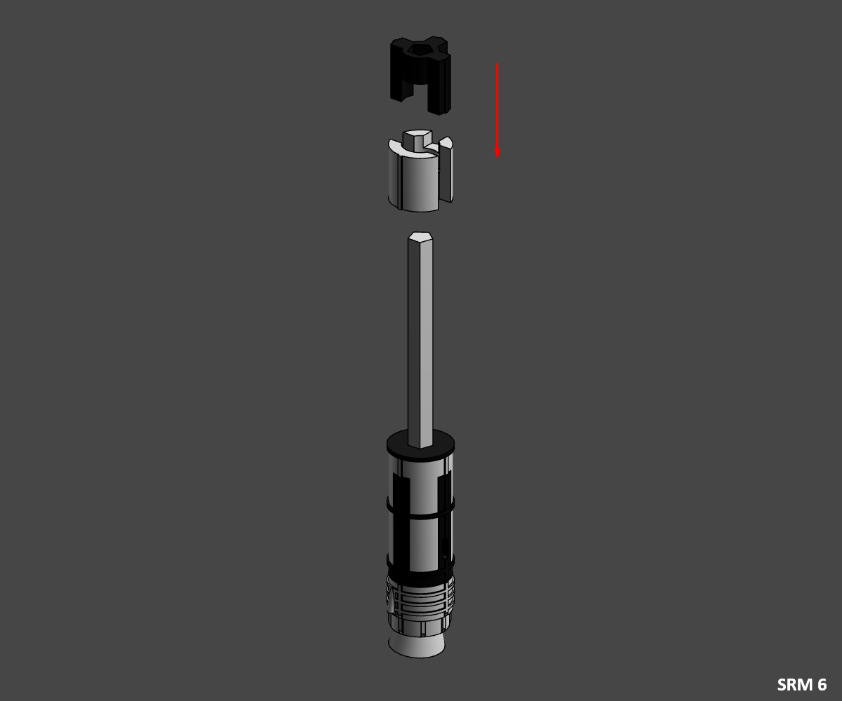
SRM 6
⚠️ Pay close attention to alignment, as shown in the pictures.
- Slide and glue the two pieces from Section 3 "SRM_S3_Black" and "SRM_S3_White" onto the jonction rod.
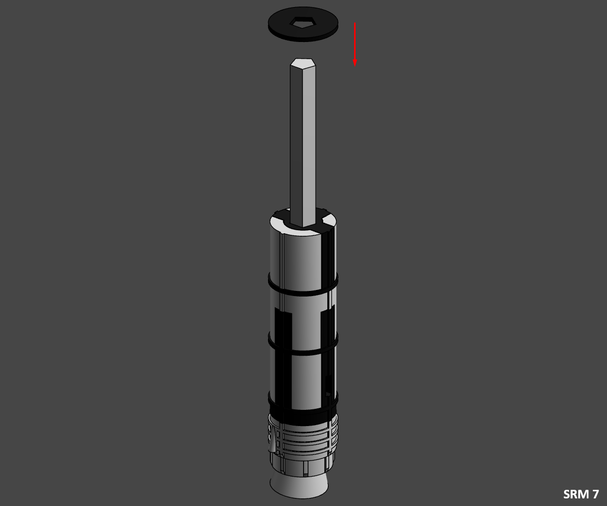
SRM 7
- Slide and glue an "SRM_Ring_Black" ring onto the jonction rod.
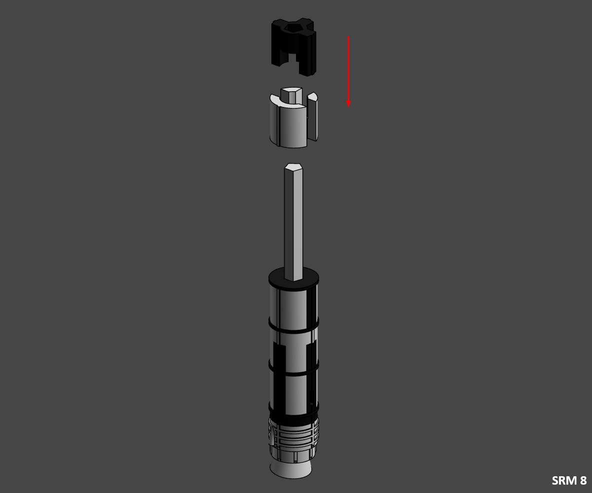
SRM 8
⚠️ Pay close attention to alignment, as shown in the pictures.
- Slide and glue the two pieces from Section 2 "SRM_S2_Black" and "SRM_S2_White" onto the jonction rod.
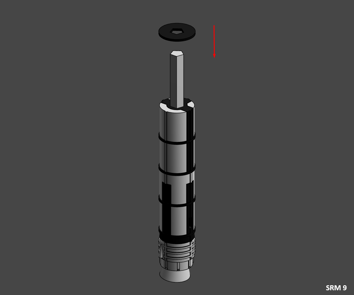
SRM 9
- Slide and glue an "SRM_Ring_Black" ring onto the jonction rod.
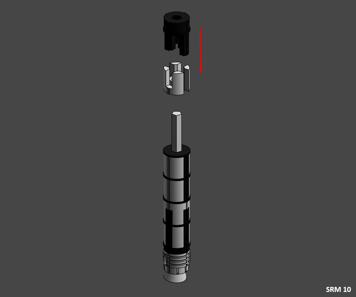
SRM 10
⚠️ Pay close attention to alignment, as shown in the pictures.
- Slide and glue the two pieces from Section 1 "SRM_S1_Black" and "SRM_S1_White" onto the jonction rod.
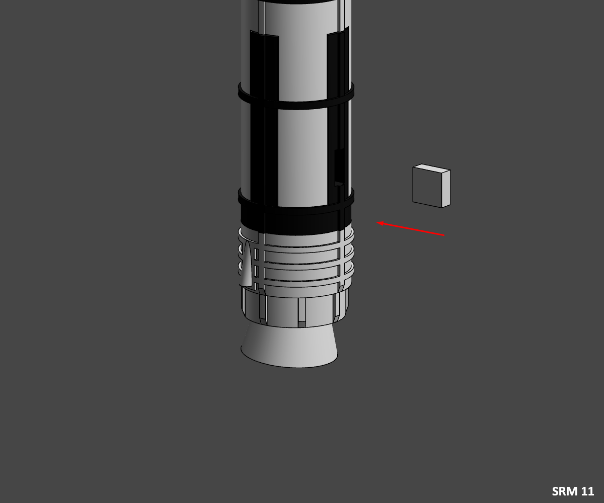
SRM 11"
- Glue the junction piece "SRM_Jonction_Bot_White" in the slot provided in the junction piece "SRM_S5_Black".
Do this step a second time for the second booster before moving on.
Congratulations, you've finished assembling the two SRM, now you can assemble the stand.
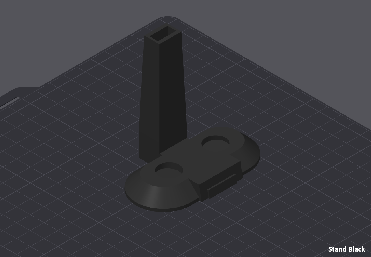
Stand
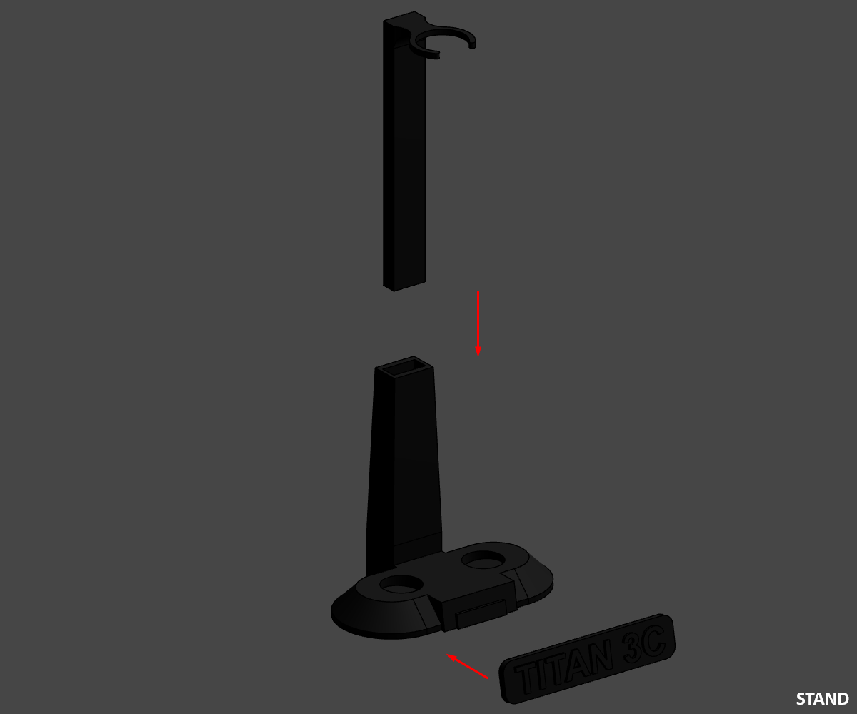
STAND
⚠️ If you have chosen the "Name_Plate_Multi" you must first paste the "Letters_White" into it.
- Stick the "Name_Plate" on the "Stand_Black" stand.
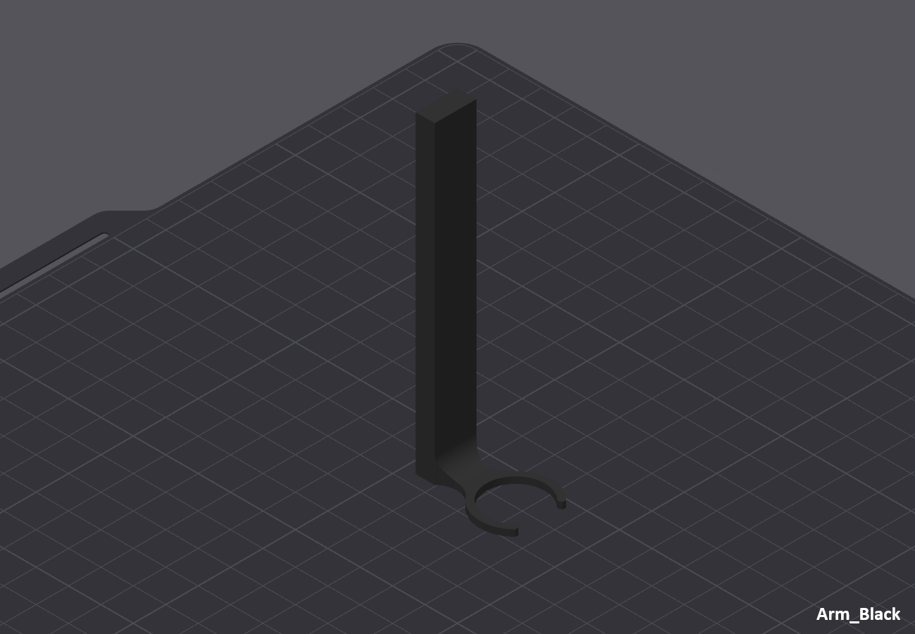
- Then slide the "Arm_Black" arm into the "Stand_Black" stand.
Congratulations, you've finished assembling the Stand, now you can assemble Final stand.
Final Assembly
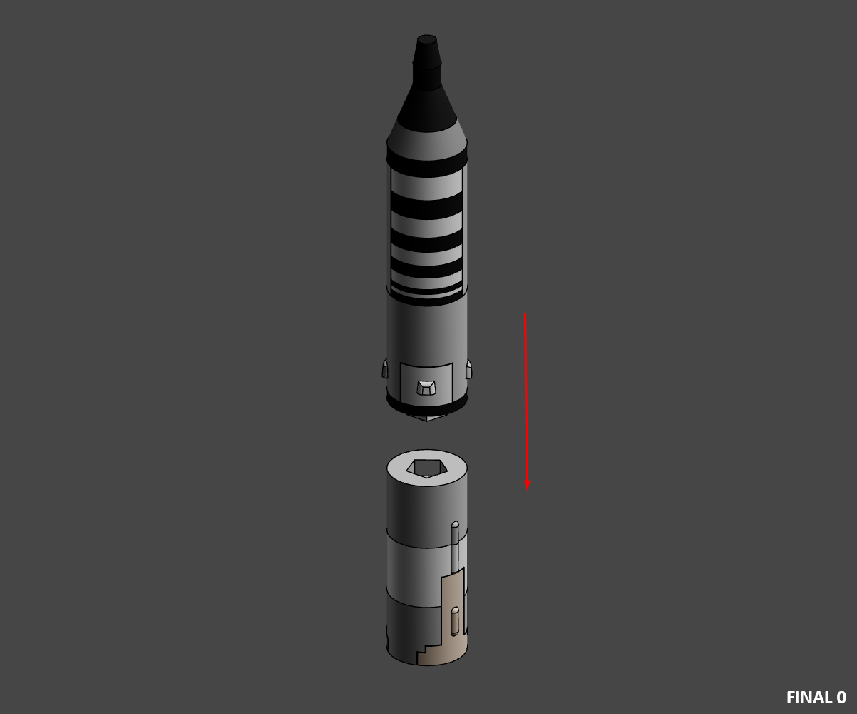
Final 0
- Glue the MOL assembly to the second stage assembly 3A-2.
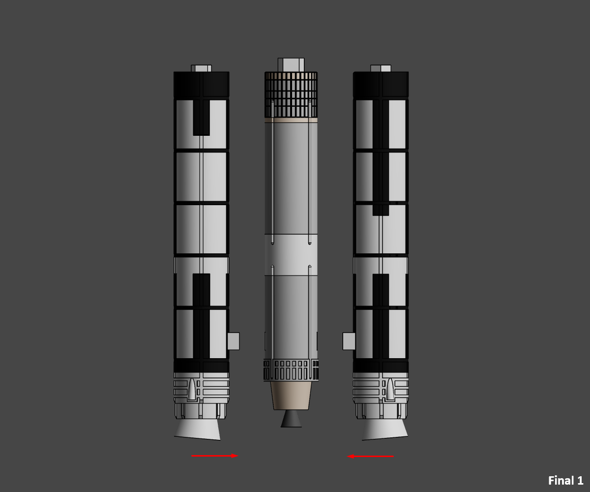
Final 1
- Glue the two SRMs into the 3A-1 first-stage assembly.
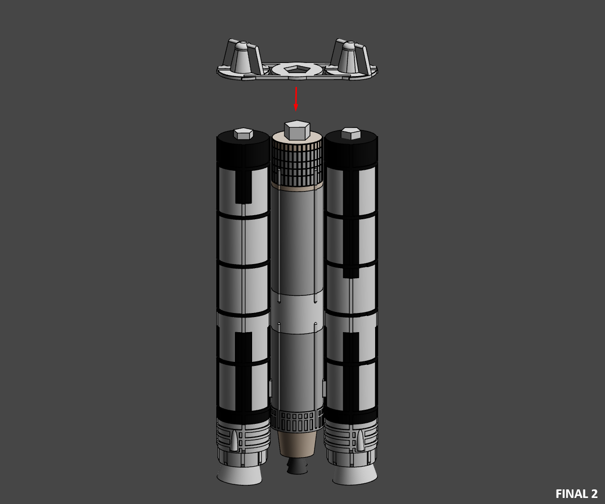
Final 2
- Glue the "SRM_Cone_White" connector to the assembly.
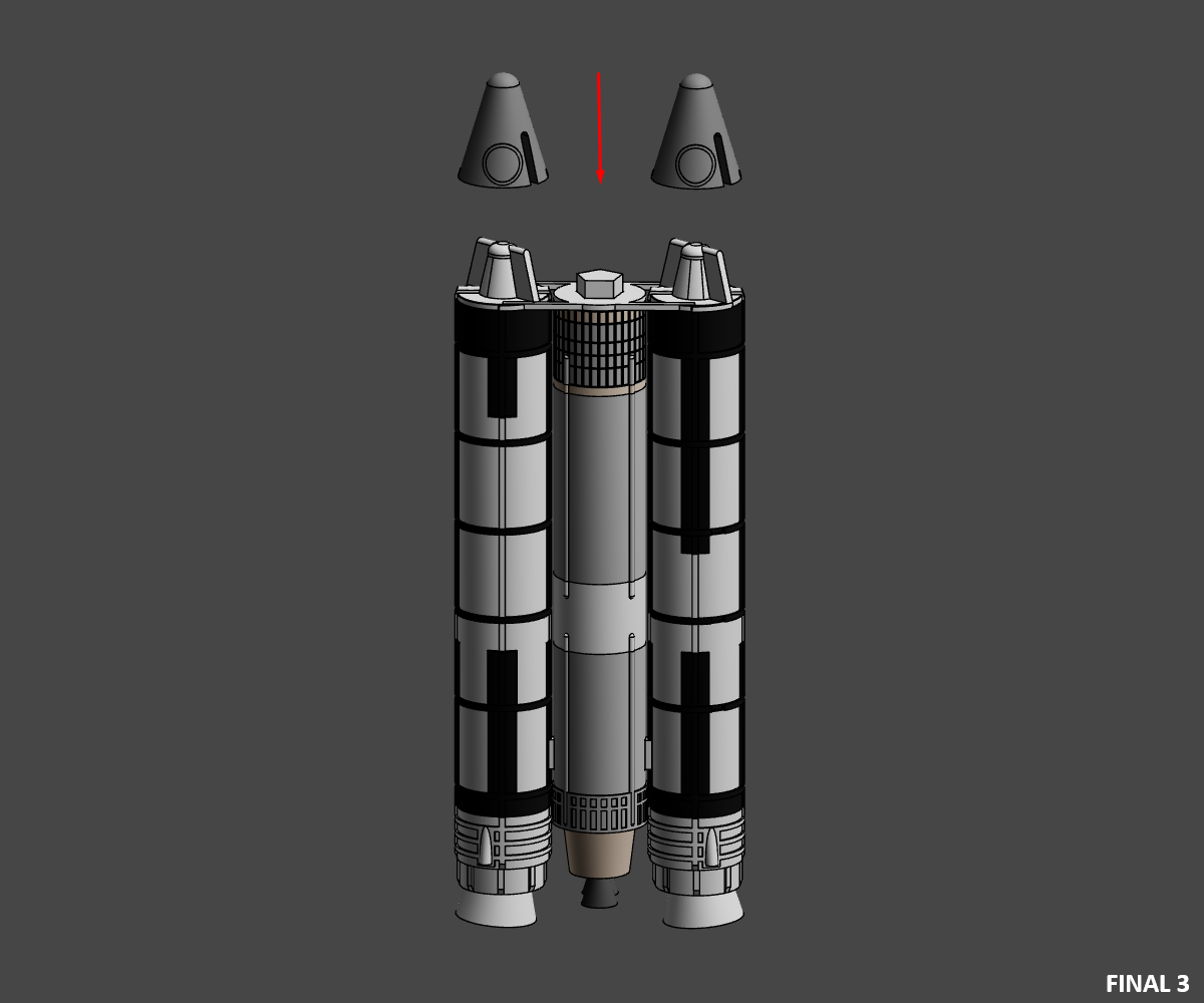
Final 3
- Then glue the SRM cones "SRM_Cone_Metal".
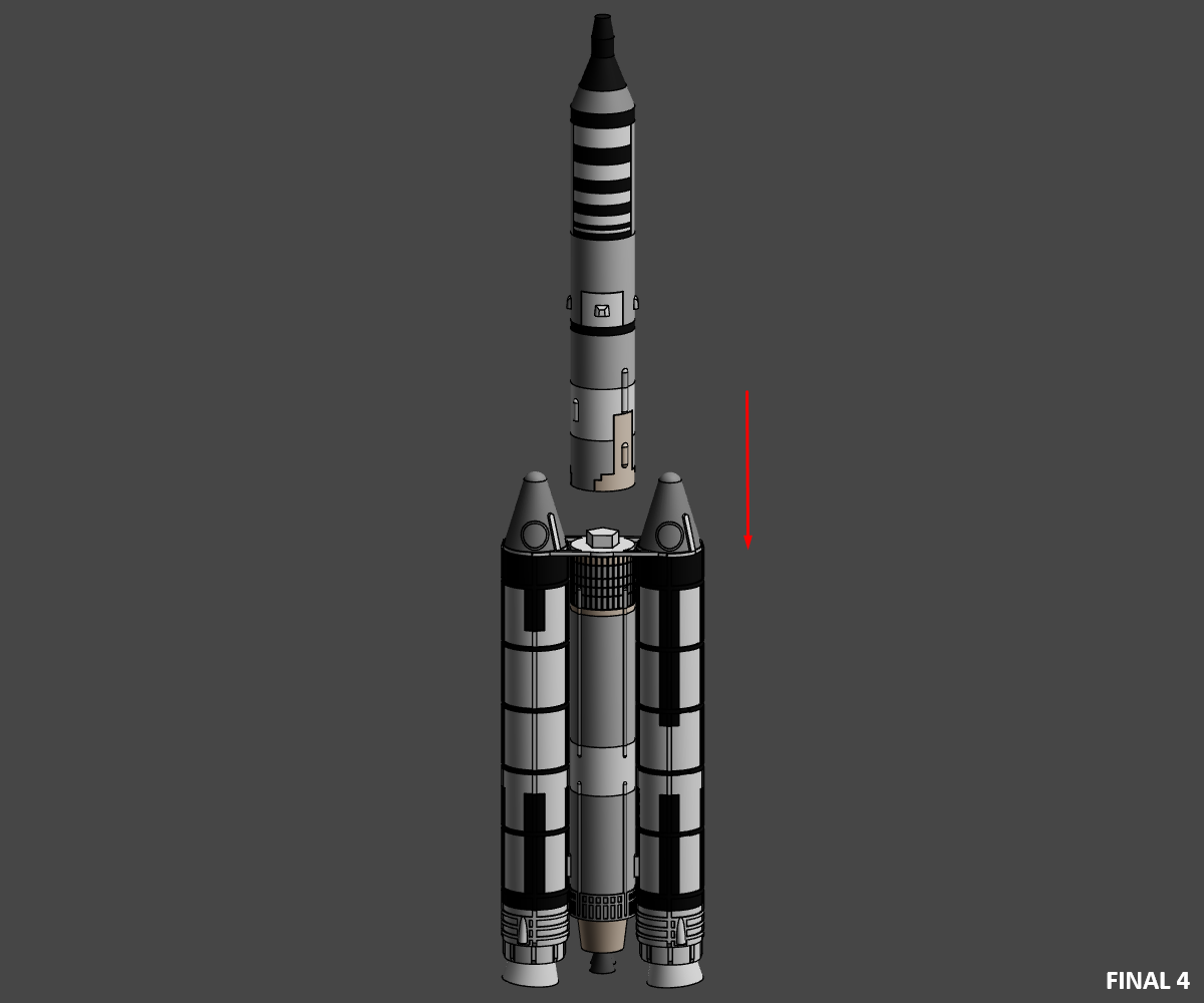
Final 4
- Then glue the MOL/3A-2 assembly to the 3A-1/SRM assembly.
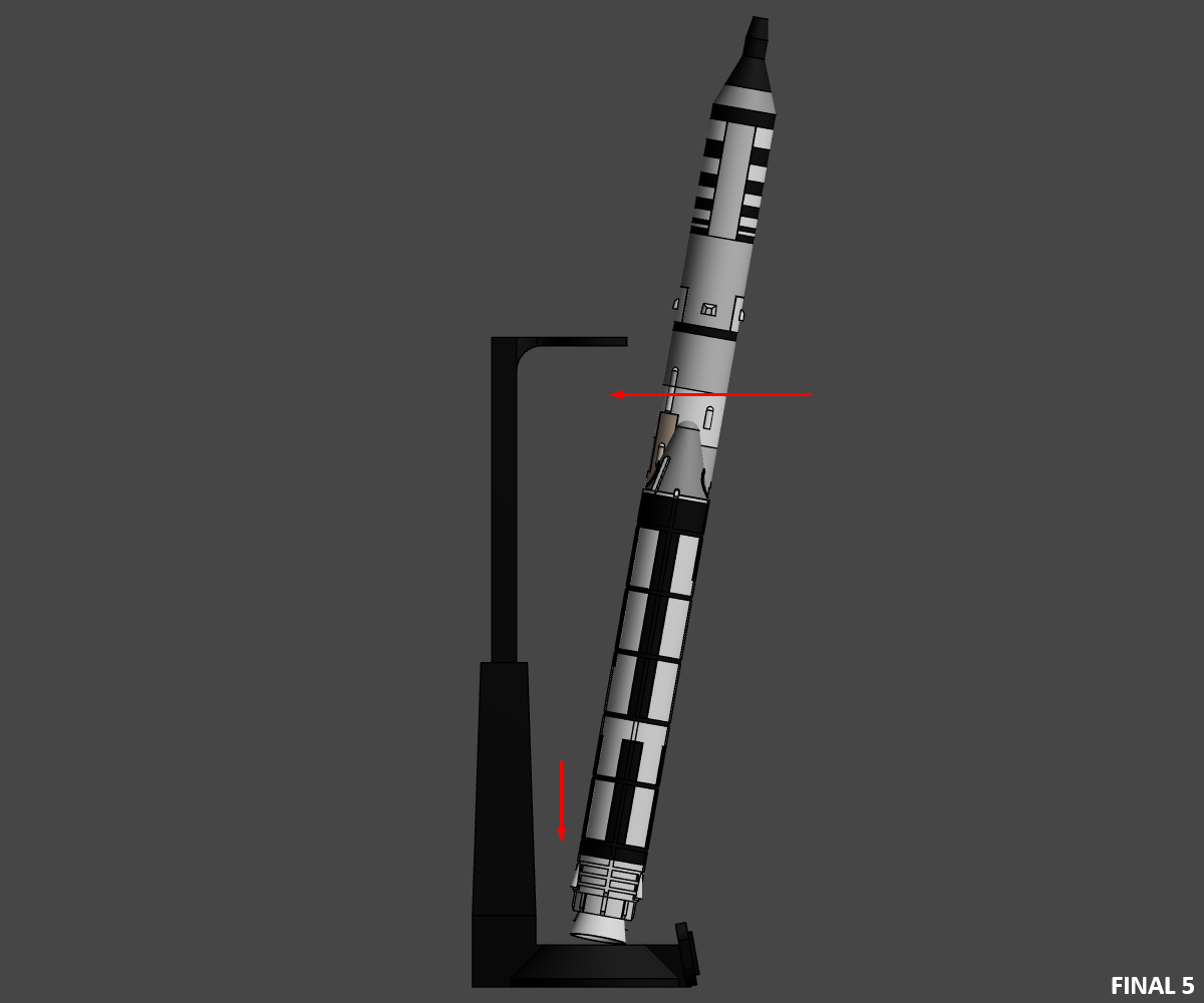
Final 5
- Then position the rocket Titan 3C on its stand.
Finish
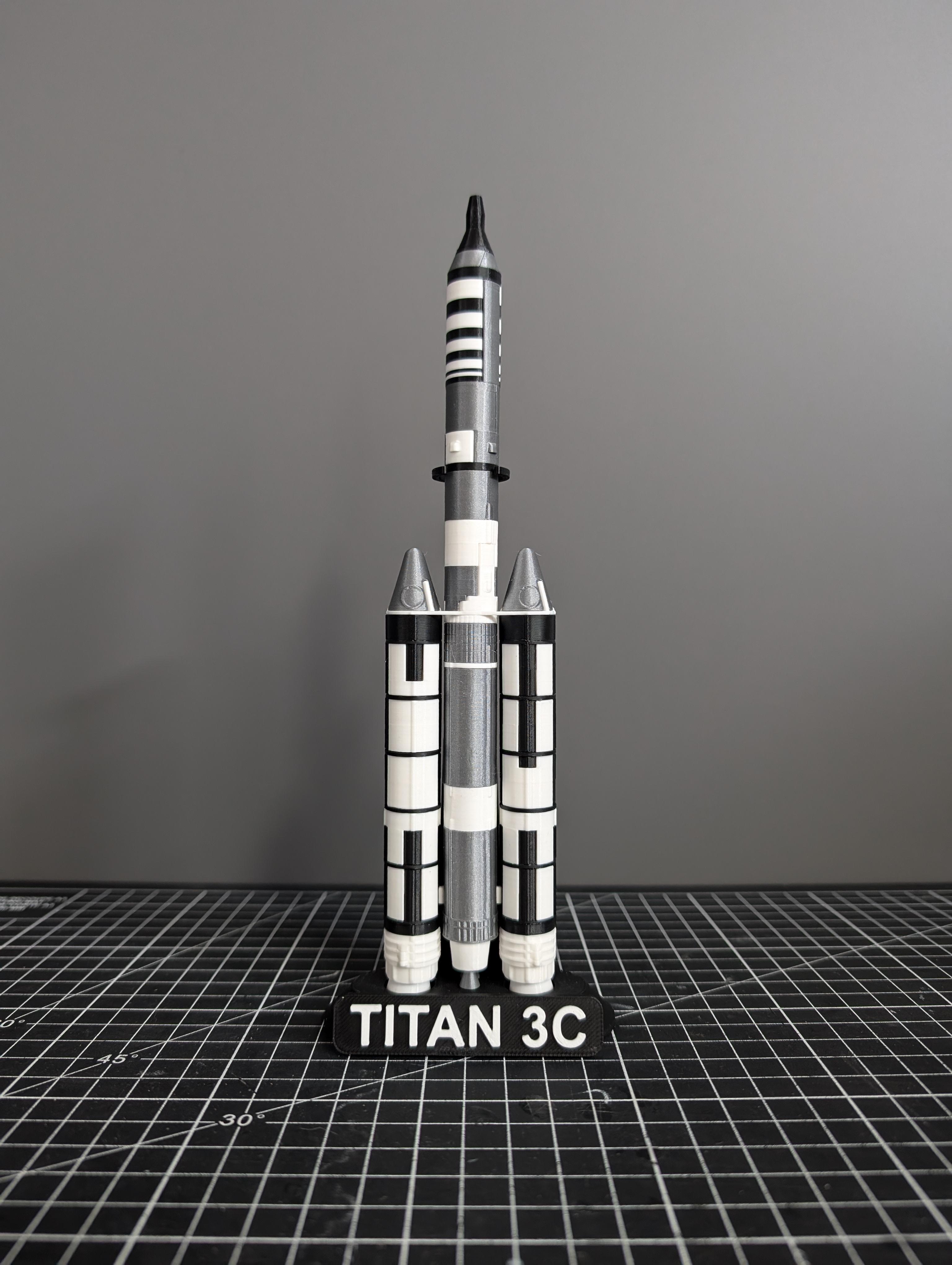
Congratulations on finishing the printing and assembly of the Titan 3C.