Tiny V/A Meter With INA219


Tired of replugging your multimeter when you want to measure both voltage and current on a small project? Tiny V/A meter is the device you need!
There is nothing new about the INA219 high side current sensor. There are plenty of good projects out there that utilizes its ability to measure both current and voltage on a load. I originally got inspired by youtuber Julian Ilett and his "10 Minute Arduino Project - INA219 Current Sensor" video. But I wanted a compact meter with a simpel interface and a 3D printed case - so I decided to make that myself.
About the INA219 sensor:
The INA219 is able to measure ±3.2A with a resolution of 0.1mA. It does this by measuring the voltage drop over the 0.1 ohm resistor on the PCB. So the sensor will introduce a very small voltage drop but only 320 mV in worst case (3.2A). As an example at 100 mA the drop is only 10 mV. If you want to, it is possible to change the resistor to get higher range or resolution. At the same time the sensor is also measuring the bus voltage with a resolution of 4 mV. In my experience the voltage readings are very precise. The precision of the current readings depend on the actual resistance of your resistor. They are typically with 1% tolerance (but not sure you should trust the cheap eBay boards). I believe it should be possible to calibrate the results if you know the precise value of the resistor. But I didn't dig further into that as the precision has been good enough for my needs. The sensor has different gain settings - these will not affect the resolution but helps decrease noise in the low ranges.
Features of the Tiny V/A Meter:
- Can be powered from USB or from the power input.
- When supplied from USB the input supply can range from 0 - 26V. Only leak current of sensor affects the power input. Nice if you want to verify the capacity of a battery.
- When supplied from power input this can range from 4 - 15V. (Limitations of arduino voltage regulator).
- Selected input is detected on boot or change and will display a range message to the user.
- Can display voltage, current, power & mAh simultaneously.
- mAh can be reset.
- One button interface with short / long press.
- Select INA219 ranges: 26V / 3.2A, 26V / 1A or 16V / 0.4A.
- Select sampling rate 100, 200, 500 or 1000 ms.
- Enable/disable sensor sleep to lower leak current in sensor.
- Settings are stored in EEPROM and reloaded on boot
- Serial interface
- Prints results on serial. Can be used for logging.
- Change settings with serial commands
Supplies
1x Arduino Nano - Arduino Nano eBay example
1x INA219 sensor board - INA219 purple sensor board eBay example
1x OLED 0.96" I2C 128X64 4-pin - OLED 0.96" Blue I2C eBay example
1x TTP223 Capacitive Touch Switch - TTP223 Capacative touch button PCB eBay example
1x Female Power Supply Jack Socket Mount - Female Power Jack hole mount eBay example
1x Male Power Supply Jack - Male Power Jack with screw terminals eBay example or Male Power Jack with Push terminals eBay example
1x Slide Switch 2 Position 6 Pin - Slide switch 6 pin eBay example
Wires
1x 5 pin male connector (optional) - 2.54 male pin headers eBay example
1x 5 pin female connector (optional) - Dupont connector set eBay example or 2.54 5 pin single row connector eBay example
Heat shrink tube (optional)
Tools:
Solder iron
3D printer (if you want the 3D printed case)
Glue gun
Schematics


I made two versions of the schematics. A traditional and a picture based one. The connections are identical so you can use whatever you prefer.
Description
The OLED display and INA219 sensor are both using I2C so they need SDA and SCL connected to A4 and A5.
The output of the Capacitive touch sensor we will connect to D2 for input.
The slide switch has 6 pins - two rows of 3 pins. One row will be used to connect the power input to Vin on the Arduino. The other row will connect D6 to ground. By using internal pull-up on D6 the Arduino will be able to see whether or not it's connected to power on Vin.
Last we route the positive connector of the power input (female power jack) through the INA219 to the positive output (male power jack). This is how the sensor is able to measure the current flowing through it.
Printing the Case


The case consists of a box and a lid. Both should be easy to print and most printers are able to print them without support. But you can add support if you want to.
When finished the two parts snaps together. If you are very careful you will be able to open it up again. But the two spring locks are a bit fragile and can break if you are not careful.
No 3D printer?
If you don't have access to a 3D printer I'm sure it's possible to make another case. You can buy a project case/box of plastic or aluminium. Or you can make something yourself from wood or cardboard. Be creative!
Assembling the Lid


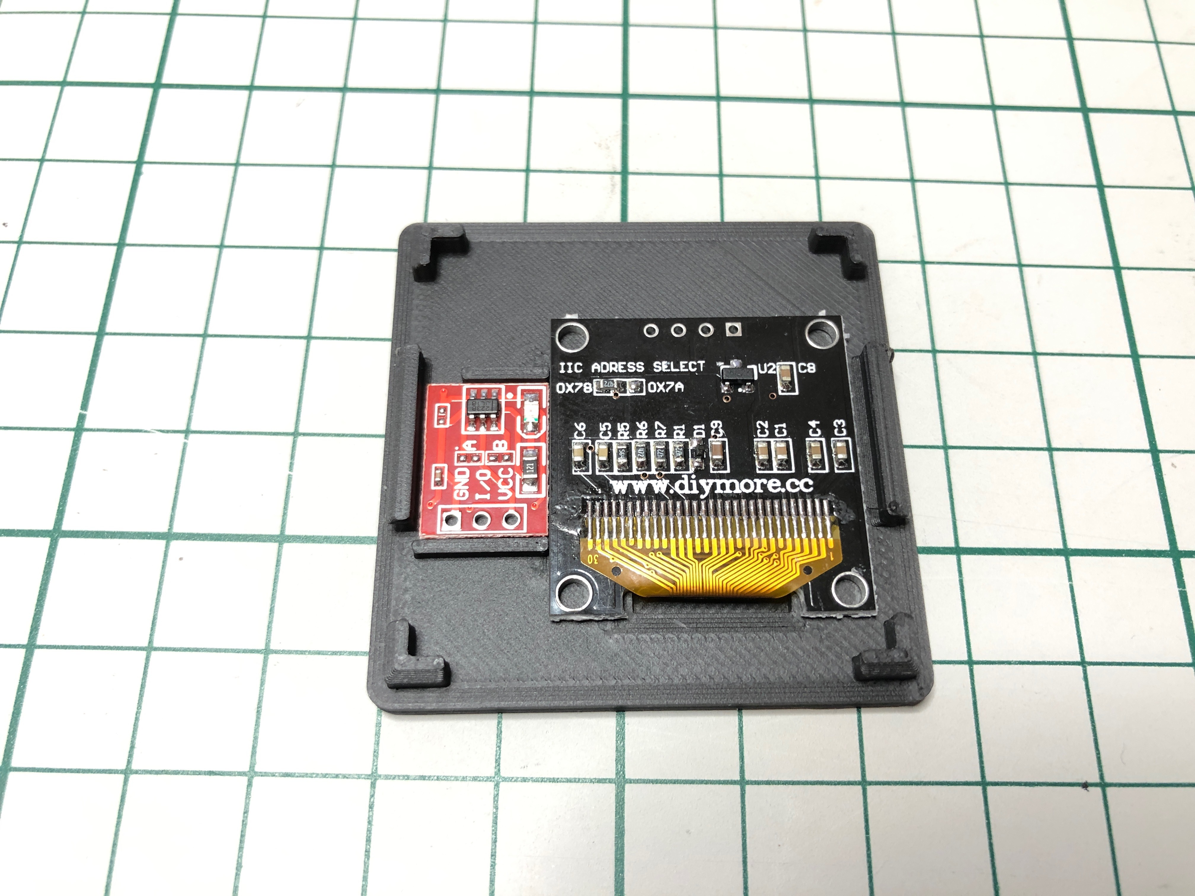
The lid holds the OLED screen and the capacitive touch button. Solder wires on the components before gluing them in place with a glue gun. Beware of the OLED screen - sometimes the glass is mounted askew on the PCB. So align that before gluing it in place. If you have a 5 pin connector then add that to the wires. If you don't it's still possible to wire the screen & button directly to the Arduino - but it's a bit harder to work with.
Assembling the Main Box


Mount Female power jack and the slide switch and screw them in place. If you can't find any small screws that fits the switch you can just glue it in place. I think that I got mine from an old DVD drive i took apart :)
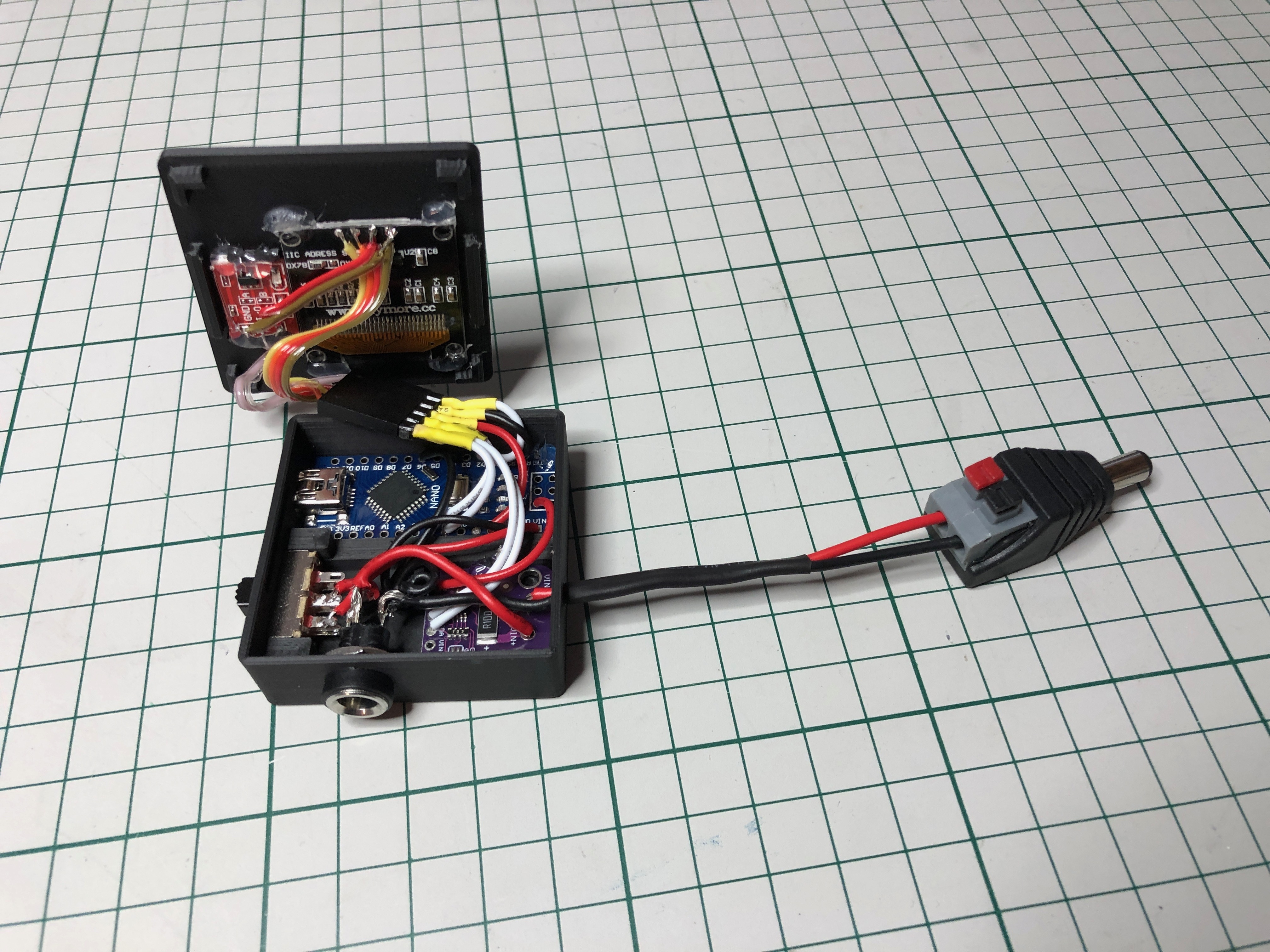
Remove pins and connectors from the INA219 (if mounted) there is not enough space for that in the box. Then fully wire the Arduino and INA219 before gluing them in place in the box. Again add the 5 pin connector if you have it - or just wire it directly to the lid.
Then complete the wiring to switch and power jacks. On the slide switch solder wires to the two pins closest to the female power jack on both rows. This way you can slide the switch towards the USB to select USB power. And slide the switch towards input for input power. Easy to remember!
Don't close the case yet! It's best to test that everything works first.
Programming the Arduino

If you don't already have the Arduino IDE installed get it from arduino.cc
You also need to install the the two libraries U8g2 and Adafruit INA219. Both are available in the library manager. For Adafruit INA219 make sure you get version 1.0.5 - the newer versions require additional libraries and flash memory, but does not provide any additional functionality at this time.
Next get the source code attached in this Instructable (Tiny-VA-Meter.ino and FlashMem.h) or get the latest version from my GitHub Tiny-VA-Meter Git. Now open Tiny-VA-Meter.ino with the Arduino IDE.
Connect the Tiny V/A Meter to your computer with a USB cable.
From tools select Board: "Arduino Nano", Processor: "ATmega328P" and the correct port. You might need to change processor to "ATmega328P(Old bootloader)" depending on your arduino. If you have communication errors try that.
Hit the upload button and wait until it has finished.
Test That Everything Is Working
Before closing up the case it's a good idea to check that everything is connected correctly. You can follow these steps to verify all components:
1. From USB power the Display should light up and display readings (regardless of the slide switch position).
2. Check that you can switch menu by tapping the button.
3. Apply power to the input and check that the meter displays the correct voltage.
4. Try shifting the slide switch and verify that the meter displays the range messages.
5. Now you can try to set the slide switch to input power and disconnect the USB. The meter should still work.
6. Finally you should be able to connect a load or device to the output and check that the sensor is reading the current draw.
If all these steps was succesfull your meter should be working perfectly! You can snap the lid in place now!
Learn to Navigate the Menu

When booting the meter will start by showing the avaliable input range depending on the position of the slide switch: "Input range: 0-26V 3.2A" or "Input range: 4-15V 3.2A". The message will only show for a few seconds, but you can skip with a short press. If the slide switch is changed after boot a new message will appear again for a few seconds.
In brief you navigate by short press and select by long press (1 sec).
The meter has 3 main pages: V/A display, V/A/W/Ah display & settings. A short press on the button will jump between these pages.
On the V/A/W/Ah page you can reset mAh with a long press.
On the settings page you can enter settings with a long press. Now you can again navigate between different settings with short press. The available settings are "Sensor range", "Refresh rate" & "Sensor sleep". You toggle each setting by long press. When navigating past the last setting the meter will return to the V/A display menu.
Using the Serial Interface

When connected to a PC with USB you can use the Arduino Serial Monitor (or another terminal) to communicate with the Tiny V/A Meter. It uses baudrate 115200.
With the selected sampling rate the meter will transmit all readings over serial and you can easily read that in the terminal.
But you can also change settings on the Tiny V/A Meter with serial commands. Make sure to select "Newline" as line ending.
Any invalid command will display the help menu:
Commands:
- reset (reset mAh)
- read (Reply with latest results)
- log x (Auto tx of sampels - x can be on or off)
- sleep x (INA219 sleep between samples - x can be on or off)
- refresh x (Set screen & serial refresh rate. x can be 100, 200, 500 or 1000)
- range x (Set INA219 range. x can be 0 for 3.2A, 1 for 1A or 2 for 0.4A)
For example type "refresh 1000" to change the sampling rate to 1 sec. Or type "log off" to disable automatic transmissions of results. The meter will reply with "OK" if succesful.
Done!


Now use it to measure something fun :)
I have tried to add all the features that I find useful. But feel free to do your own modifications. And please share if you are able to make some awesome improvements to the Tiny V/A Meter!
Updated 14/06-2020:
Changed driver and added more features! Not covered by this guide yet - but you can check it out on my GitHub.