Ultra Compact LiDAR Distance Meter/Range Finder
34586 Views, 348 Favorites, 0 Comments
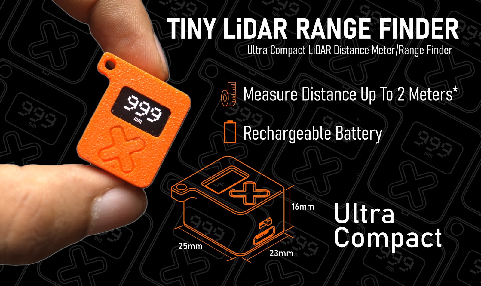
Ultra Compact LiDAR Distance Meter/Range Finder

I am a big fan of OLED displays. If you look at my recent projects, you can see that most of them feature OLED displays. While researching a project, I came across the smallest OLED display available, a tiny 0.49-inch 64x32 pixel display. I decided to build a super tiny gadget using this display. In addition to the display, I used a tiny battery and the tiny microcontroller Xiao ESP32 for this project. So this is what I came up with “tiny LiDAR laser range finder ” anUltra Compact LiDAR Distance Meter/Range Finder
Supplies
Supplies
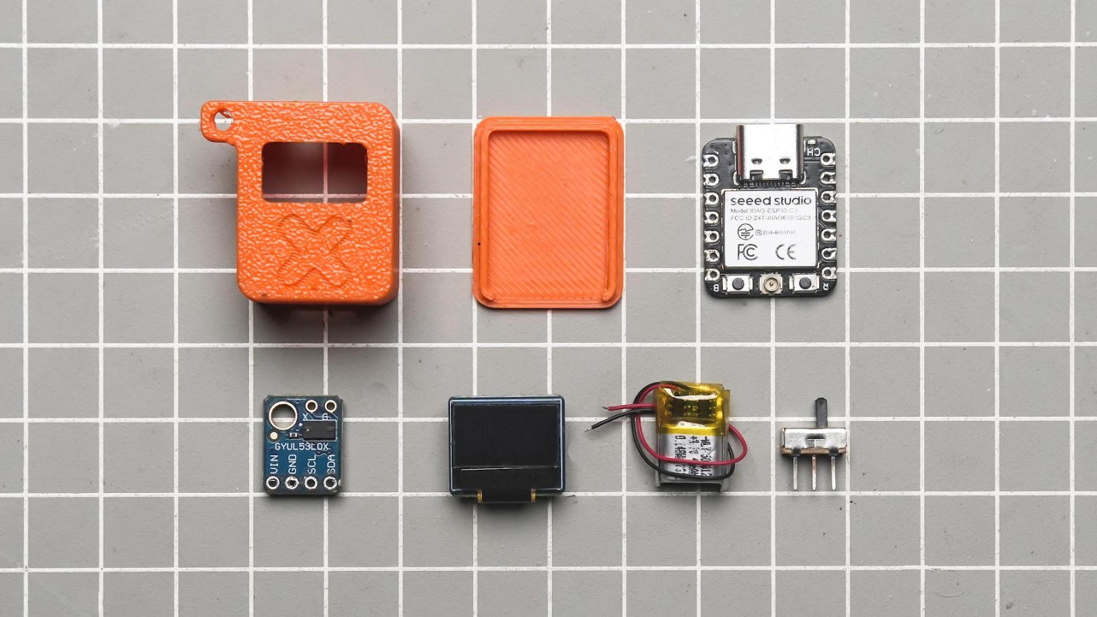
Parts
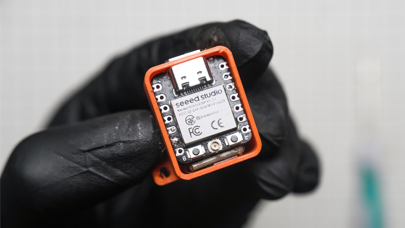
- Seeed studio xiao esp32c3
- Micro battery
- 0.49inch OLED Display Module
- VL53L0X TOF Based LIDAR Laser Distance Sensor
- Slide switch
- B-7000 multi-Purpose glue
- 30 AWG wires
Tools
- Soldering iron kit
- Wire cutter
- Third-Hand Soldering Tool
Used 3D printer
Used 3D printing filaments
Designing in Autodesk Fusion 360

I utilized Fusion 360 to plan and design my project, which required careful space optimization. I needed to fit all the parts into the smallest form factor possible while ensuring practicality, including sufficient space for wiring and easy assembly. First, I imported all the 3D models of the parts and tried different configurations by placing the parts in various positions. Once I found the optimal configurations, I built the enclosure around them. All design files are provided below.
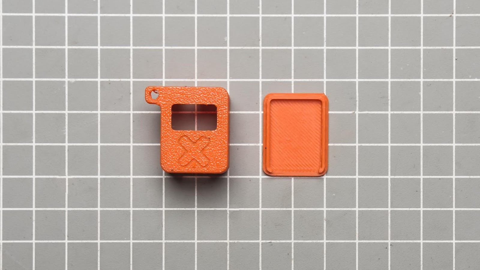
3D Printing
After exporting all the models into.STL files, I 3D printed them using my Anycubic printer. For this project, I used Numakers PLA+ Outrageous Orange filaments. You can find the.STL files from step one.
Flashing Code to Xiao ES32C3

I always like to upload the code to the microcontroller before assembly. I am using Arduino IDE for flashing the code. follow these tutorials for setting up IDE for Seeed Studio XIAO ESP32C3 and learn more about this board
Make sure to install all required libraries into Arduino IDE
How to install library tutorial video link
Here is the complete code for the project
 //The range readings are in units of mm.
#include <Wire.h>
#include <VL53L0X.h>
#include <Adafruit_GFX.h>
#include <Adafruit_SSD1306.h>
#include <MedianFilter.h>
#define SCREEN_WIDTH 128 // OLED display width, in pixels
#define SCREEN_HEIGHT 64 // OLED display height, in pixels
// Declaration for an SSD1306 display connected to I2C (SDA, SCL pins)
Adafruit_SSD1306 display(SCREEN_WIDTH, SCREEN_HEIGHT, &Wire, -1);
VL53L0X sensor;
MedianFilter test(10, 0);
// Uncomment this line to use long range mode. This
// increases the sensitivity of the sensor and extends its
// potential range, but increases the likelihood of getting
// an inaccurate reading because of reflections from objects
// other than the intended target. It works best in dark
// conditions.
//#define LONG_RANGE
// Uncomment ONE of these two lines to get
// - higher speed at the cost of lower accuracy OR
// - higher accuracy at the cost of lower speed
//#define HIGH_SPEED
#define HIGH_ACCURACY
void setup()
{
  Serial.begin(9600);
  Wire.begin();
 if(!display.begin(SSD1306_SWITCHCAPVCC, 0x3C)) { // Address 0x3D for 128x64
    Serial.println(F("SSD1306 allocation failed"));
    for(;;);
 }

  sensor.init();
  sensor.setTimeout(500);
#if defined LONG_RANGE
  // lower the return signal rate limit (default is 0.25 MCPS)
  sensor.setSignalRateLimit(0.1);
  // increase laser pulse periods (defaults are 14 and 10 PCLKs)
  sensor.setVcselPulsePeriod(VL53L0X::VcselPeriodPreRange, 18);
  sensor.setVcselPulsePeriod(VL53L0X::VcselPeriodFinalRange, 14);
#endif
#if defined HIGH_SPEED
  // reduce timing budget to 20 ms (default is about 33 ms)
  sensor.setMeasurementTimingBudget(20000);
#elif defined HIGH_ACCURACY
  // increase timing budget to 200 ms
  sensor.setMeasurementTimingBudget(200000);
#endif
  // Clear the buffer.
   display.setTextColor(WHITE);
}

void displayDistance( int val)
{
  display.clearDisplay();
  display.setTextSize(3);
  display.setCursor(40,32);
  display.print(val);
  display.setTextSize(1);
  display.setCursor(60,55);
  display.print("mm");
  display.display();
  delay(100);
}

void loop()
{
  int o,r = sensor.readRangeSingleMillimeters();
  test.in( r );
  o = test.out();
  Serial.print(o);
  if (sensor.timeoutOccurred()) { Serial.print(" TIMEOUT"); }
  Serial.println();
  displayDistance( o );
}
Wiring Diagram
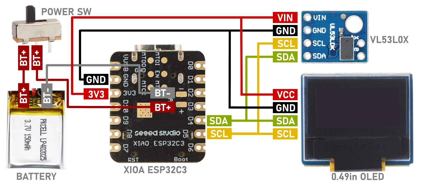
XIAO ESP32C3 Supports lithium battery charge and discharge management. Which means BMS is built in . So there is no need for an external BMS. You can charge the battery through USB port
Assembly and Wiring
Due to the small size of our project, we need to use a different approach for assembly. Since we don't have any screw holes on the parts, we can't use tiny screws to hold everything together. The best method to use is glue, which is the same manufacturing method used in most compact tech products like the AirPods, for example. We are not using hot glue here, we are using a B-7000 multi-purpose glue. Now let's start the assembly
Step 5.1
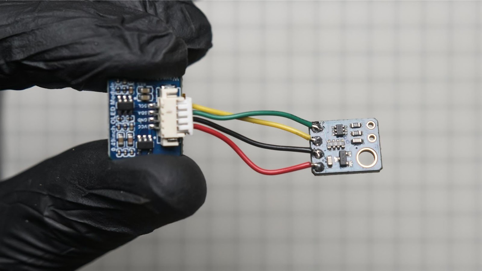
Solder all four wires from the OLED module to the sensor. Also, solder another four 20mm wires from the sensor that will be used to connect to xiao GPIO during later steps.

Step 5.2
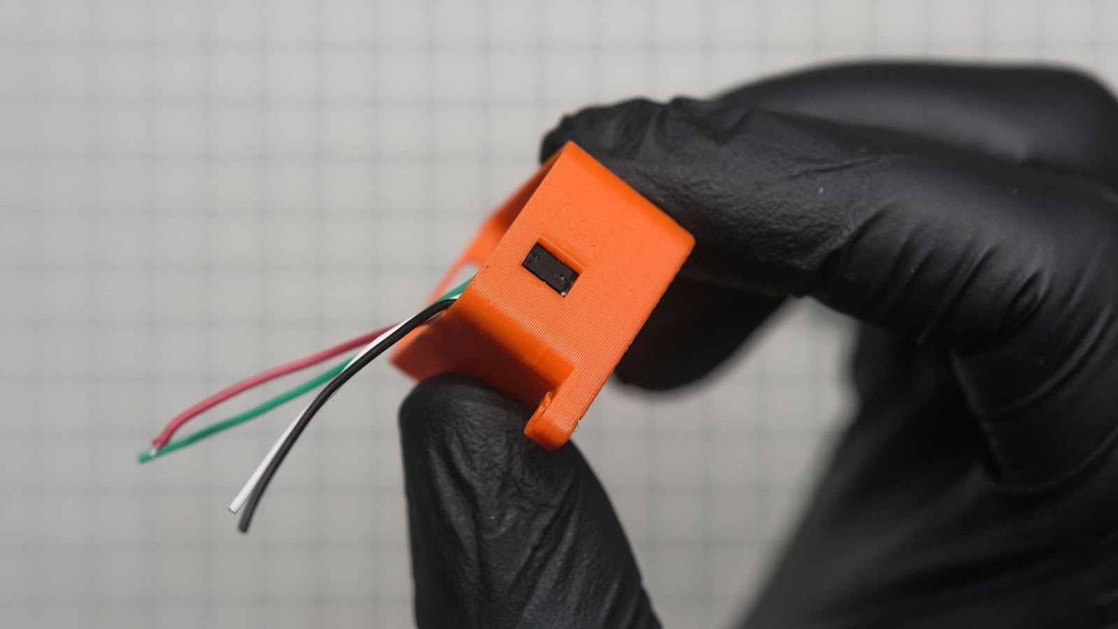
Place the OLED module into the 3d printed slot, also place the sensor on the side and make sure to align the sensor to the small window on the sides

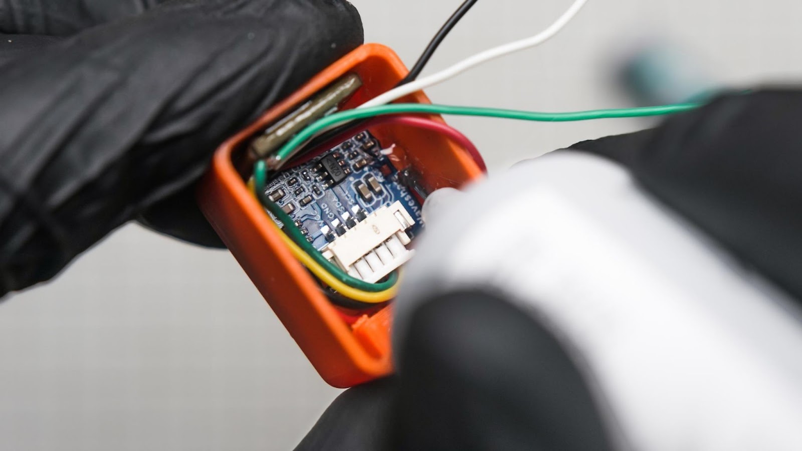
Step 5.3
Now glue the OLED module and sensor. you apply glue on the sides of the modules
Step 5.4
Glue battery on top of the OLED module

Step 5.5
Reduce the length of the switch terminals, cut the battery BT+ wire into the proper length and solder the BT+ wire into one of the switch terminals. Also, solder a small wire from the switch. which will be connected to BAT+ of the Xiao board

Step 5.6
Now place the switch into the 3d printed slot and glue it in place

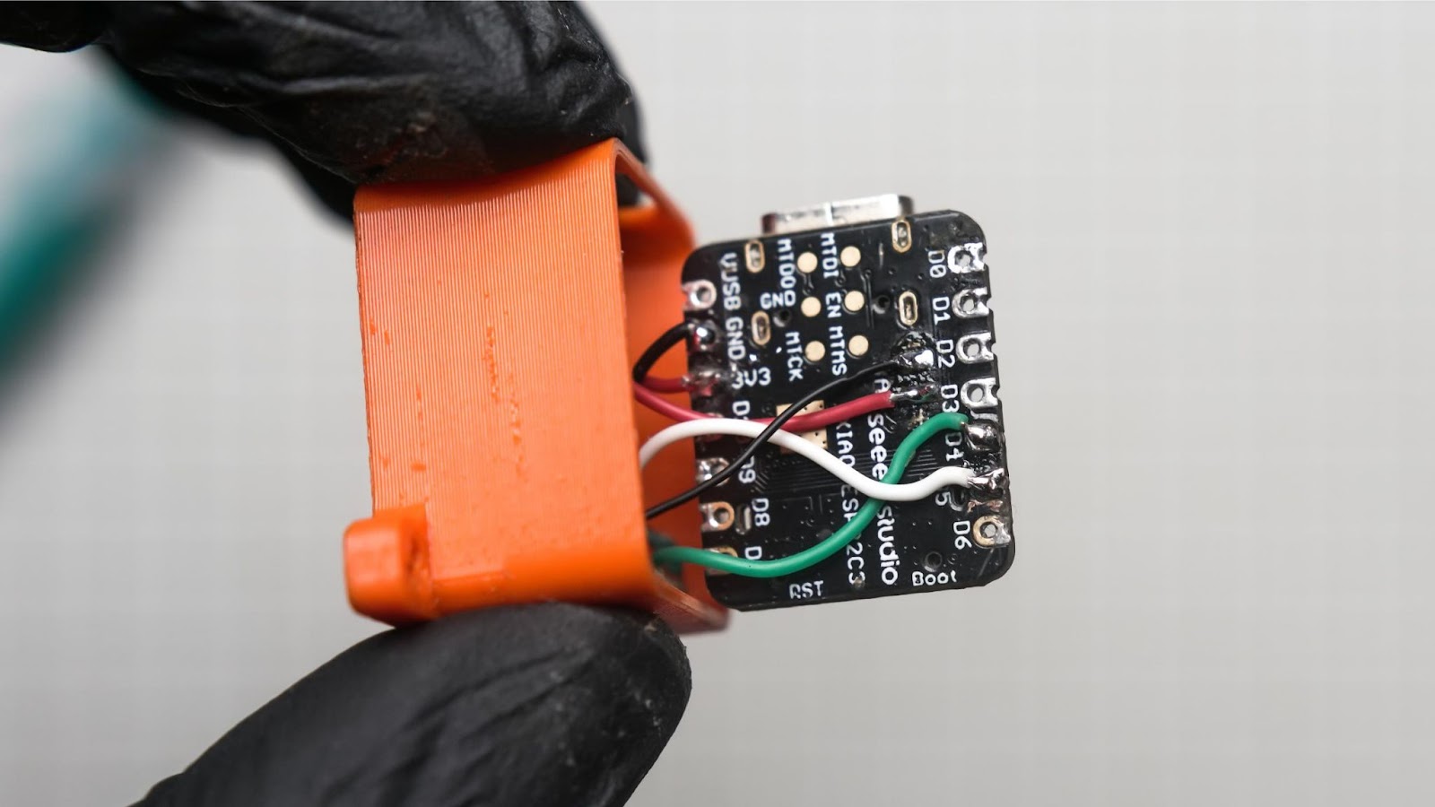
Step 5.7
solder all GPIO wires underneath the Xiao board. Power the OLED and sensor through the 3V3 pin of the Xiao. Also, connect the negative battery wires and the positive BT wires from the switch to the battery terminals of the Xiao.
Step 5.8
Push down all the wires and place the Xiao board into the 3D print. Also, align the USB port with the hole on the 3D print. And glue the Xiao board

Step 5.9
Yes !! we just completed the assembly of our project. lest power it on

Yes, it works !!
Testing
No, let's test how accurate our measurement is. I placed an object 10 cm away from our device. The measurement from our project is also displayed as 100mm, so it works well.

Final Thought

You can also add a key chain to it. you can link it with a small 3mm hole on the side. So it will be better to carry it around. Our sensor can measure up to 2 meters, but the accuracy is low. It provides reliable measurements up to 1 meter. So I suggest you use it in this range. so this is the smallest project I did. It was a great learning experience for me. I am currently planning for more projects in this same topology. so keep an eye on my page more projects are coming soon
thanks, Gokux
If you found this project helpful or inspiring, consider buying me a coffee ☕

It really helps me keep building and sharing more open-source projects.
https://buymeacoffee.com/gokuxmaker