Tinkercad Robotics for School: Human-Powered Battle Beasts!
by M.C. Langer in Teachers > 6
5926 Views, 61 Favorites, 0 Comments
Tinkercad Robotics for School: Human-Powered Battle Beasts!
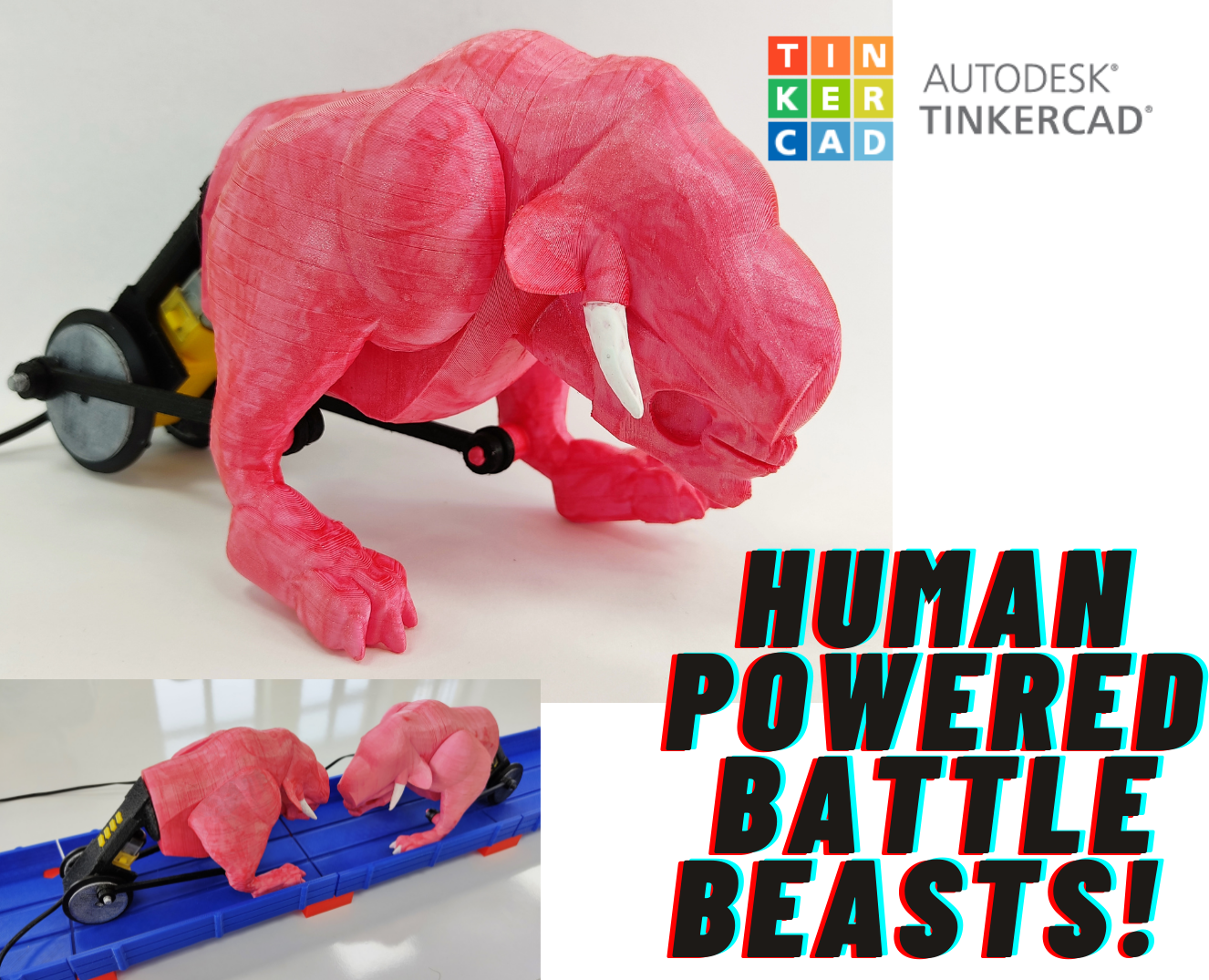
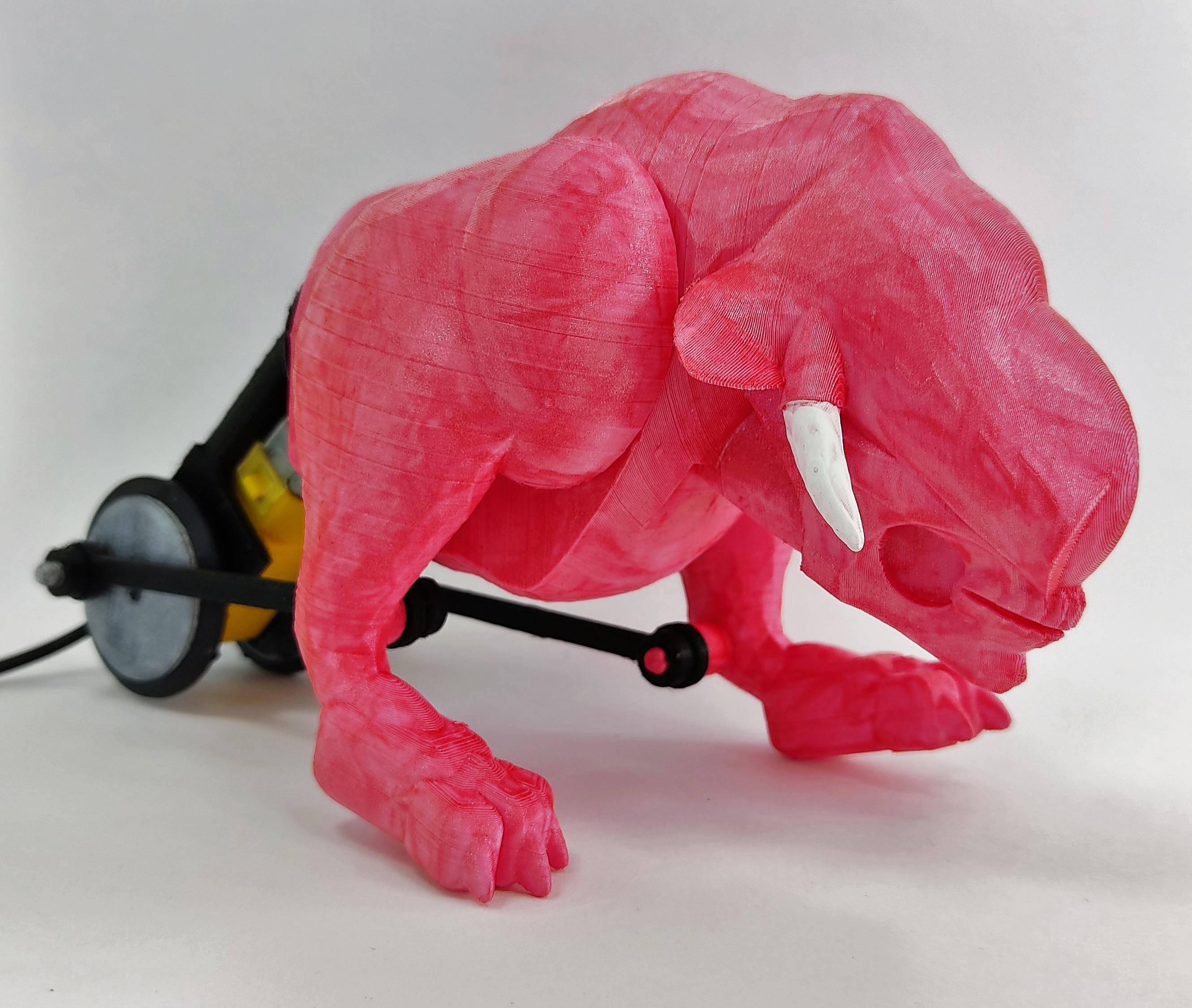
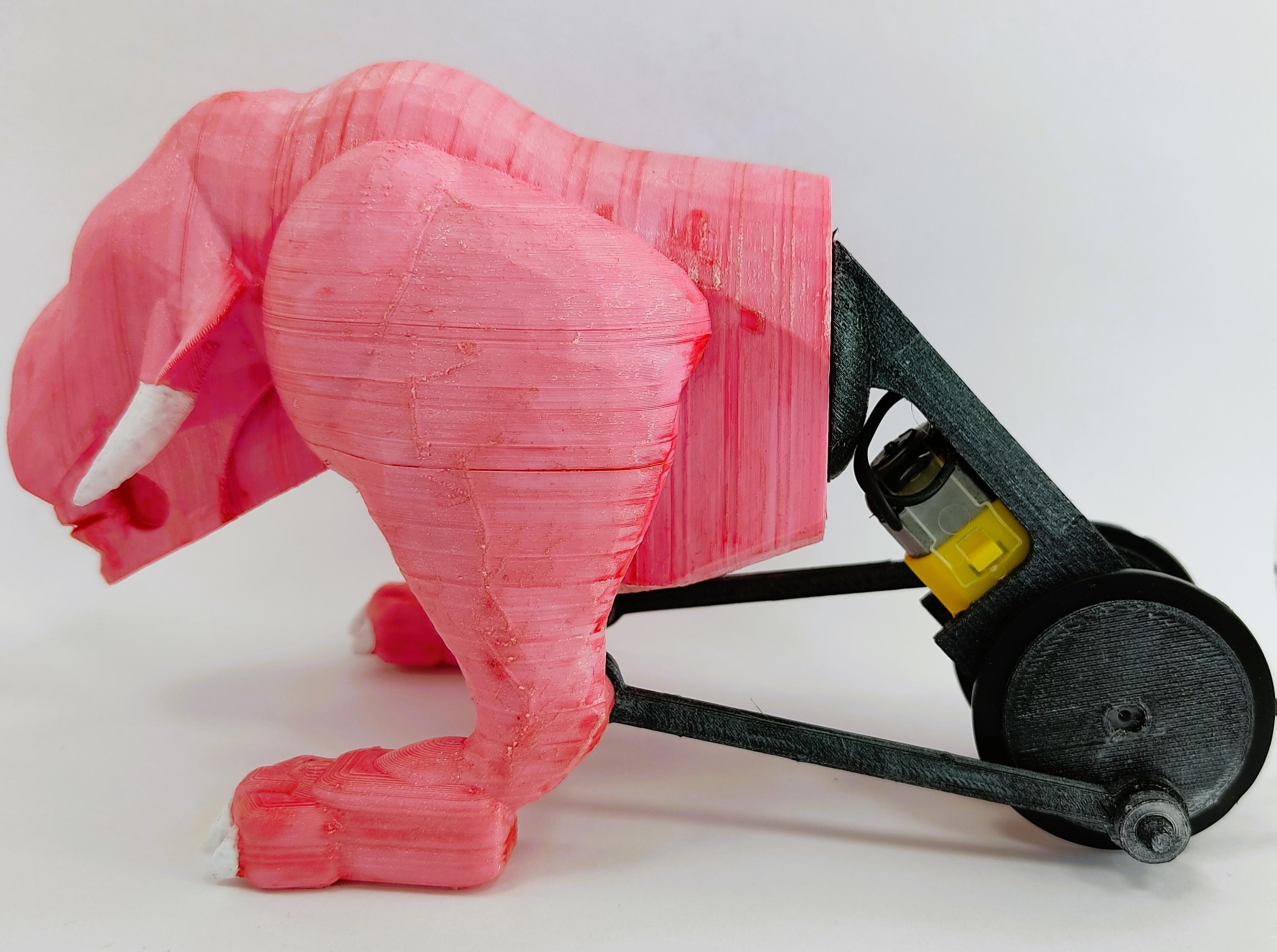
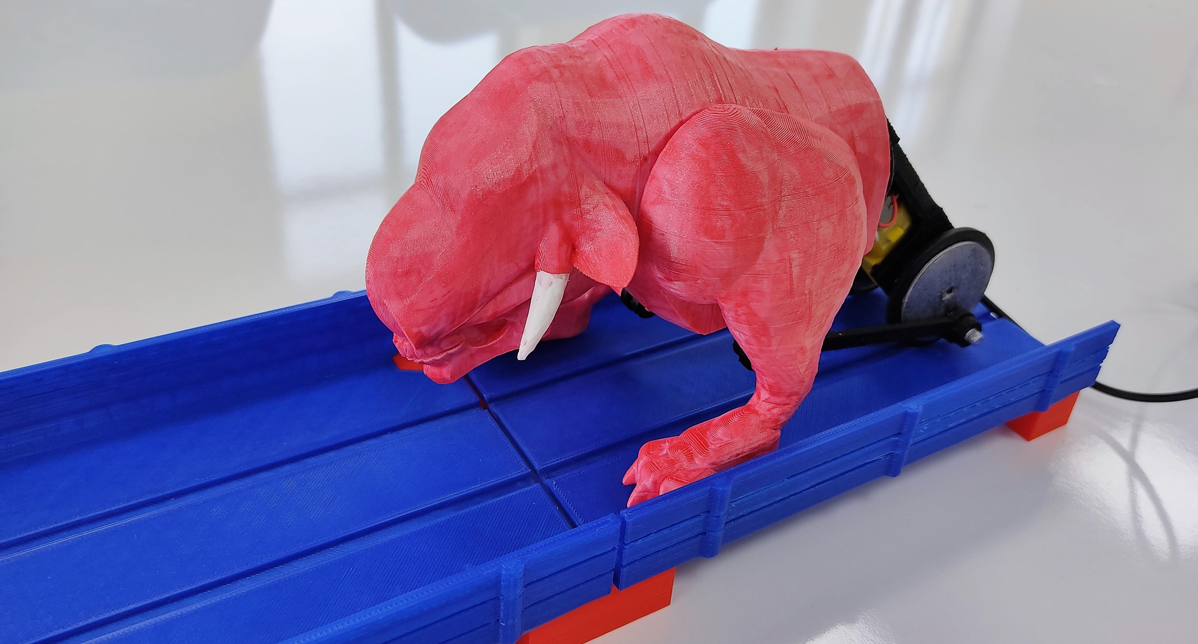
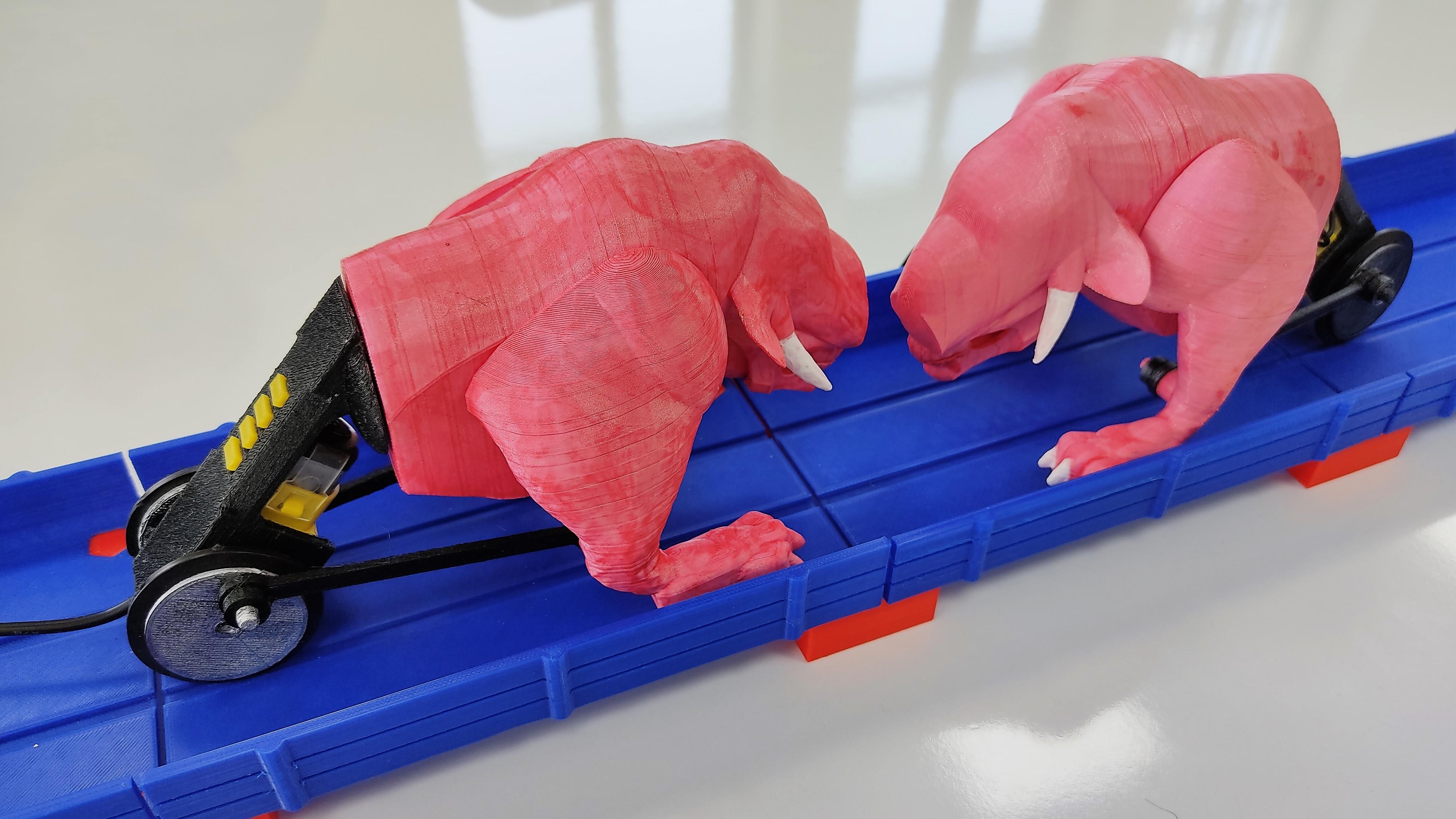
Hello! My name is Mario, and I just summoned some evil creatures from the Underworld. These beasts feed from human energy; and in order to bring them from whatever dark dimension they belong to this material plane, I had to created an unholy amalgam of human bones, animal parts and cybernetics.
Fear not, fellow maker or educator! I am not part of some pagan sect, no human law was broken, and the following instructions are not blasphemy. Quite the opposite! Follow me, and you will find not only some valuable educational content, but also a fun game that will challenge the willpower and stamina of your family, friends and students.
Welcome to the world of HUMAN-POWERED BATTLE BEASTS!
....................................................................
For this chapter of my "Tinkercad Robotics for School" series, I wanted to try something new: using an alternative source of energy, and creating a creature that looks organic (instead of my usual robot-like bots). The result is a very interesting and fun game and a great STEAM education activity, where players must spin the cranks of their devices as fast and consistent as the can, so their Battle Beast can push the other one out of the battle track.
In this instructable, I created three components, with potential to be used in other activities as well:
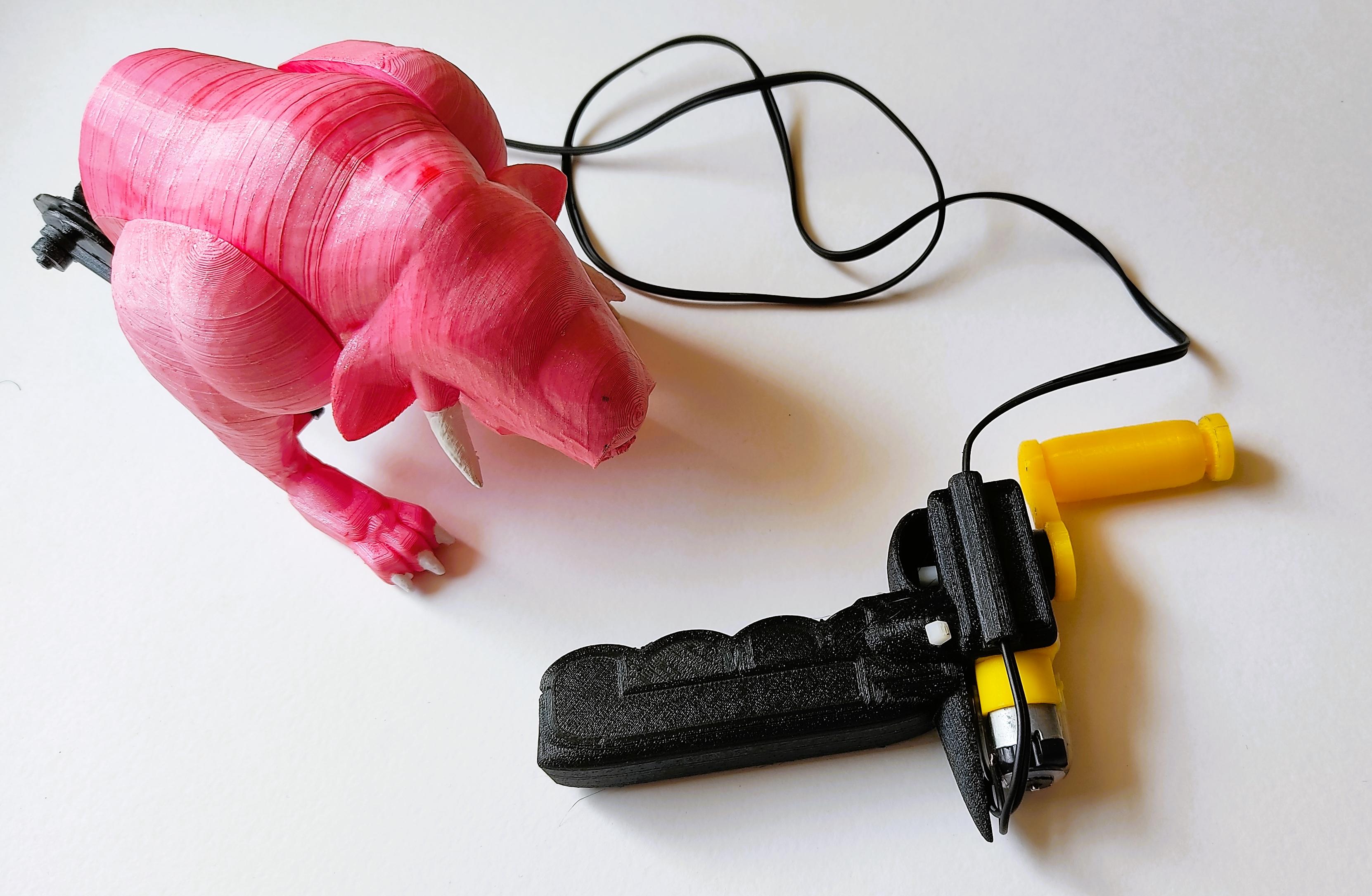
- Hand Dynamo: spinning a crank connected to a gearbox, the dynamo will generate electrical energy. This device is useful not only for this project, but for most of my previous "Tinkercad Robotics" projects.
- Robotic Machine: to test the limits of the Hand Dynamo, the Battle Beast is a 250 gr. machine that uses wheels and legs for locomotion. I call it "Pinky", because the design was inspired by one of the monsters of the very forgettable "Doom" movie, with The Rock and Karl Urban.
- Battle Track: to keep both "Pinkies" in place and facing each other during the fight, I built a platform with tracks aligned to the tires of the fighting robots. So yes, if you don't like to call it "Human-Powered Battle Beasts", you can call it "Pinky Fight".
The STEAM subjects and educational benefits of this game are:
- Science (Physics): students explore transformation of energy, from chemical (food ingested by humans), to mechanical (hand moving, crank rotating) to electrical (dynamo). This electrical energy will become mechanical again (gearbox). Besides, concepts like electric resistance, friction, inertia and simple machines are explored.
- Robotics: kids explore how to create efficient machines considering the power source constraint. This machine is a hybrid concept, using wheels and legs at the same time.
- Design and 3D Printing: this project was designed using Tinkercad. Also, students explore concepts like prototyping, ergonomics, and constraints like materials, infill and stress points. Test and improvement must be considered to create a successful Battle Beast.
- PE (Physical Education): this activity requires screen-free physical effort, where kids can be competitive in a safe way. This activity can be practiced both indoors and outdoors.
- Environment: kids learn about clean energies. Besides, this toy doesn't requires batteries, so it can be played anytime, reducing damage by leaking batteries and environmental impact. The Hand Dynamo is compatible with other simple robotics solutions.
- Art: students may be encouraged to create their own design of monsters, and paint them using different techniques.
Supplies
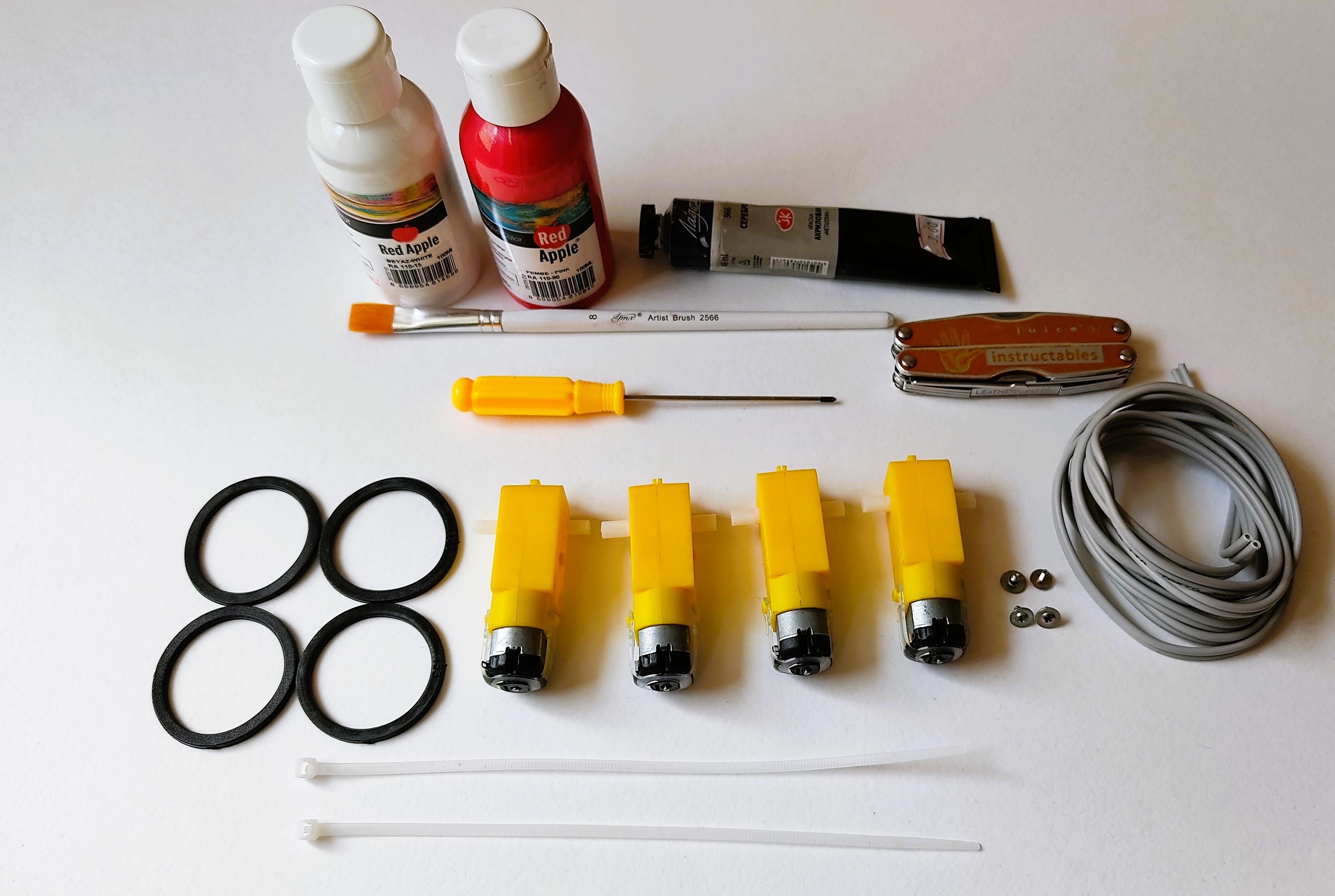
- 1 Computer with access to Tinkercad
- 1 3D printer. Material: PLA (Optional: ABS or PETG. I will explain later)
- 4 Gearbox "I" shape (like this one)
- 2 Zip-ties
- 4 sealing rubber rings for plumbing, outer diameter: 44mm; inner diameter: 35mm; thickness: 2.4mm.They will be the tires for the wheels. If you cannot find them in your area, use elastic filament to create tires of these dimensions, or adjust the dimensions of the wheels to the ones that you could get.
- Small screws with flat head (you can find them inside broken toys and some electronic devices)
- 3 meters of cable with double wire. You can also use the ones from old cellphone chargers.
- Pliers (for removing support material)
- Super-glue (cyanoacrylate, preferable with activator spray)
- Scissors (to cut the remaining zip-tie)
- Screwdriver.
- Multitool Leatherman
- Optional: acrylic paints, brushes and sandpaper.
PLEASE NOTE: the four gearboxes (specially, the four motors in them) must be similar, from the same manufacturer and preferable new. The cables must be the same type for both of the machines. The tires must have their outer imperfections removed. This to give equality of conditions to both players, and avoid unfair disadvantages due to differences in electrical resistance, friction and quality of the motors.
Hand Dynamo 1: Case
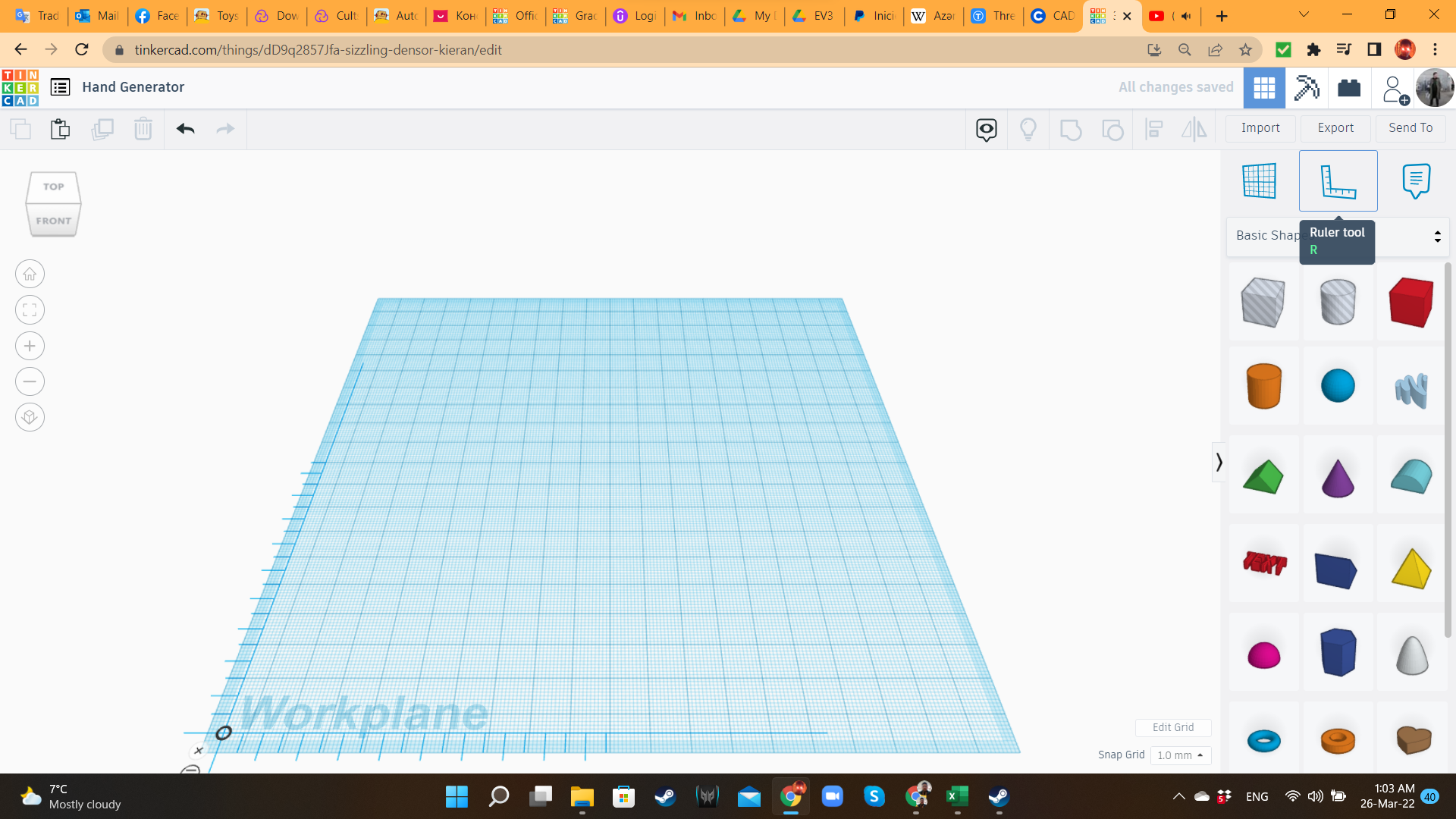
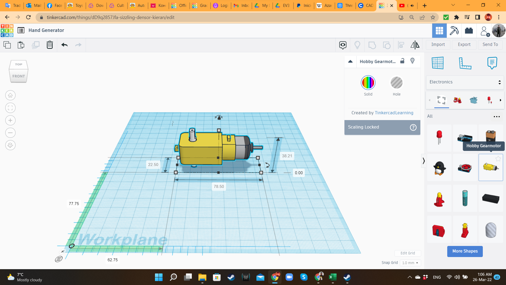
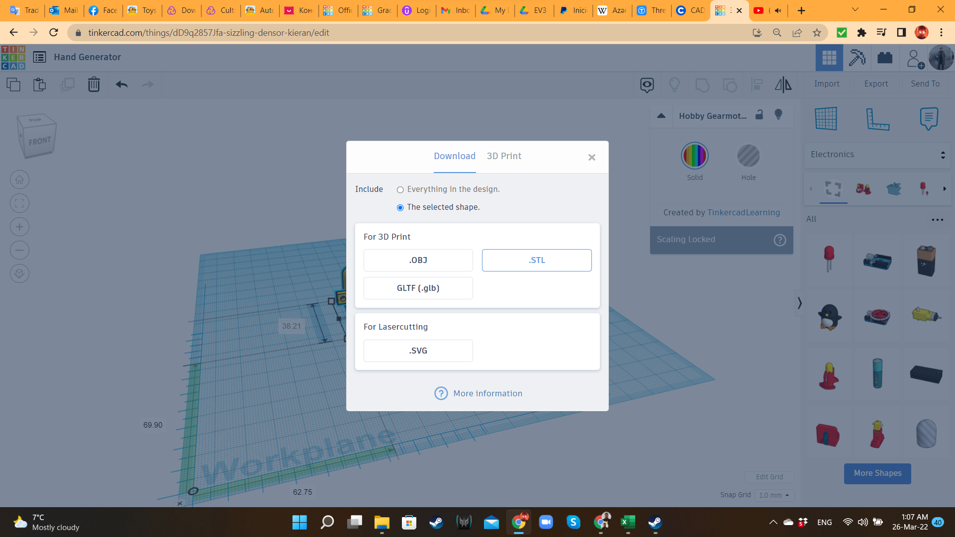
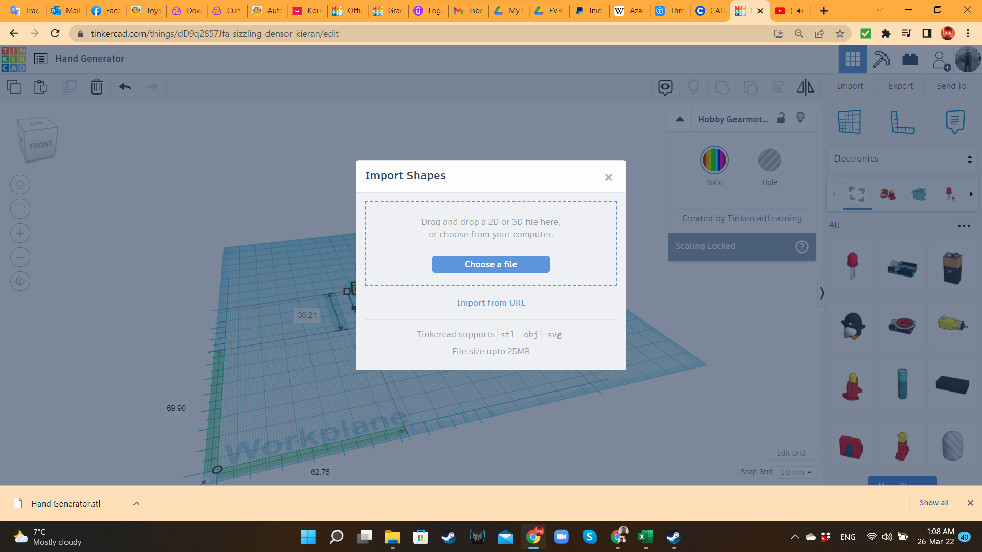
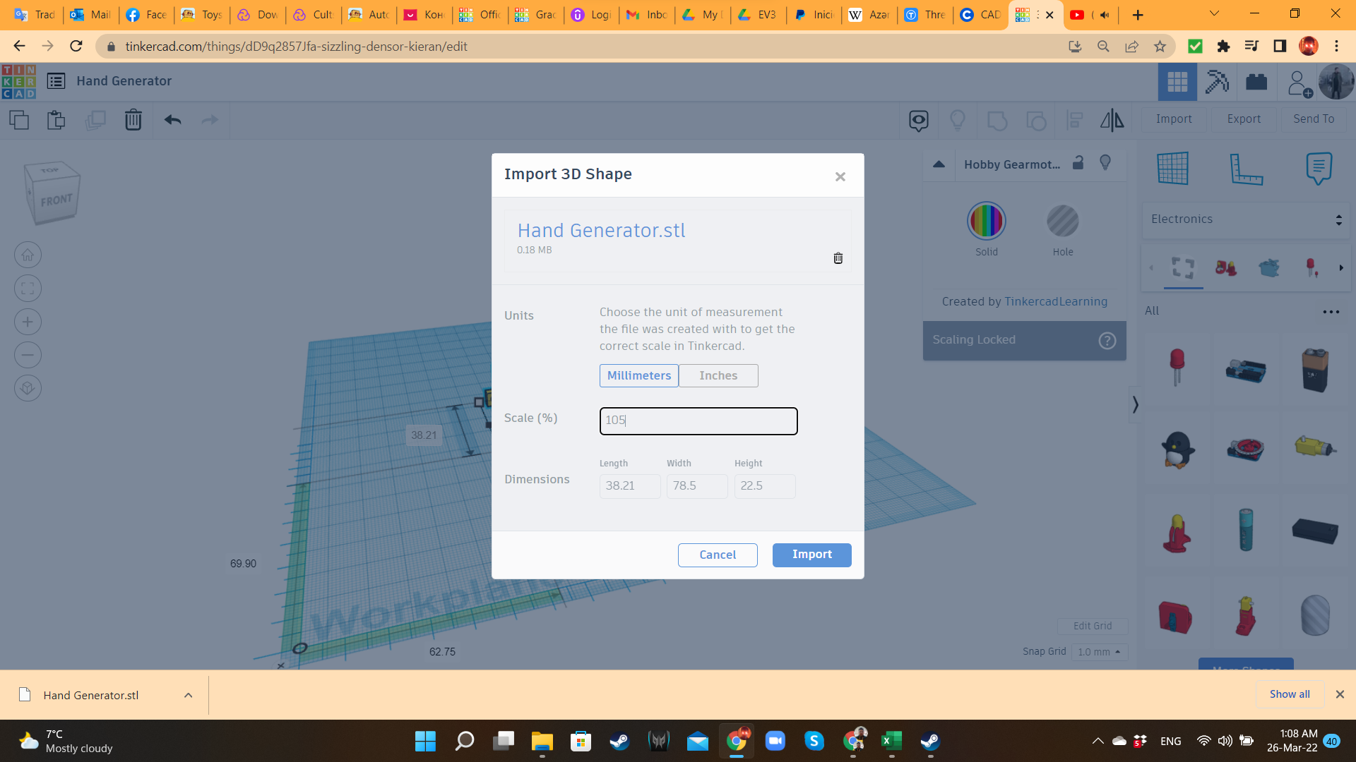
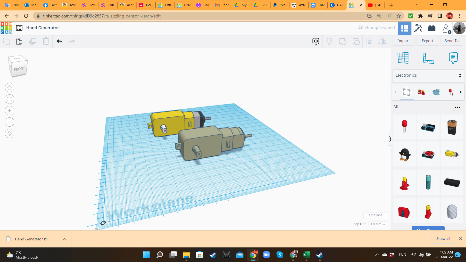
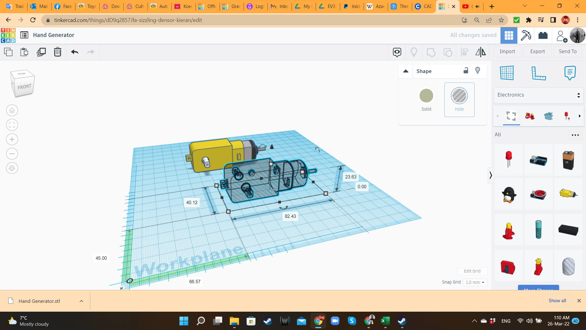
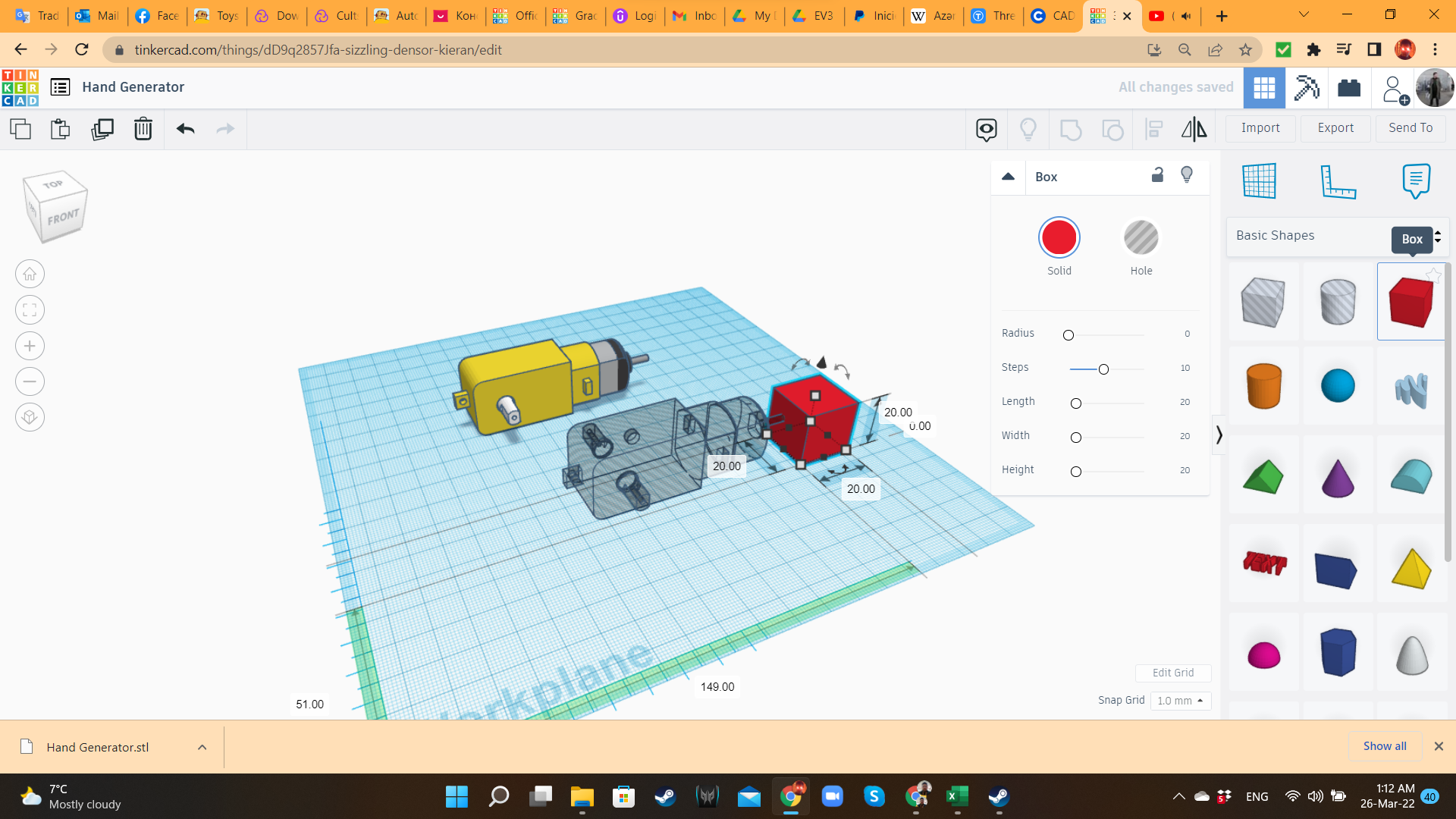
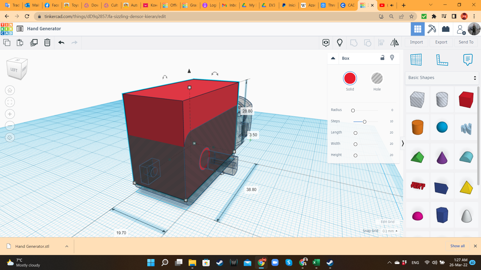
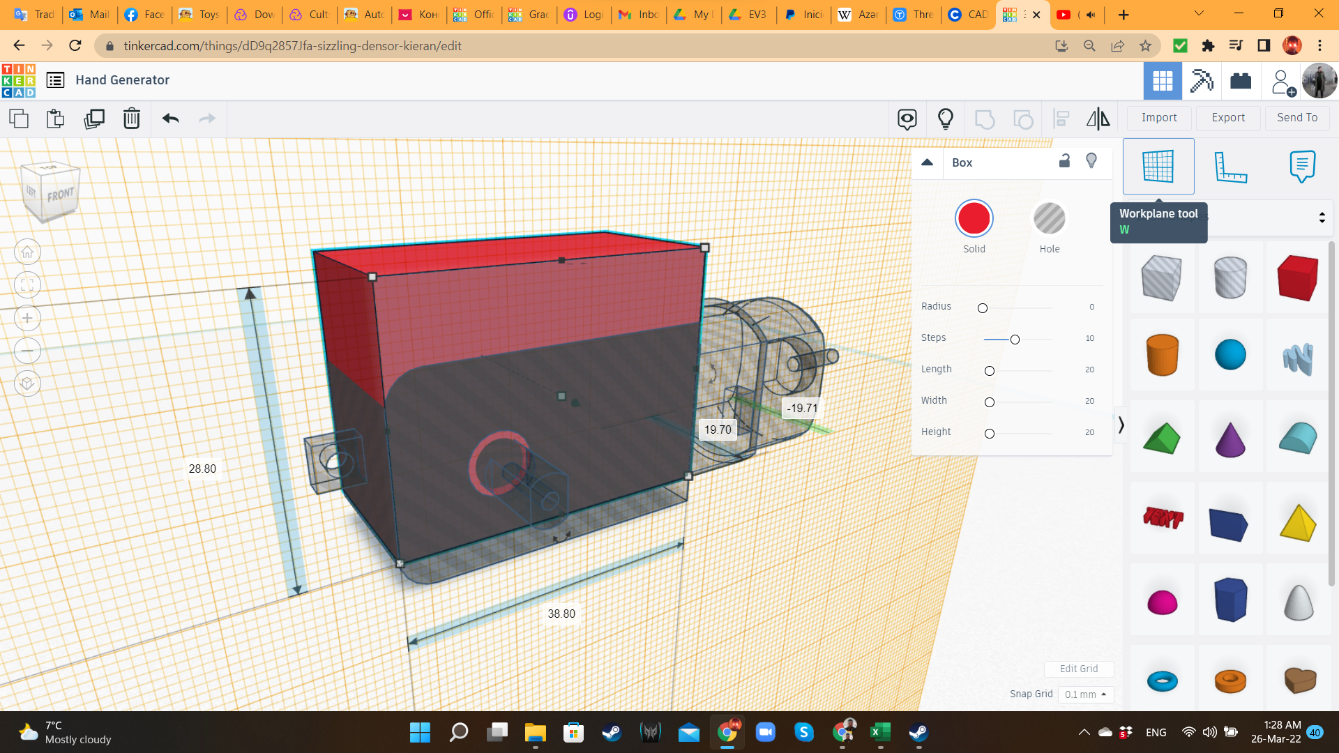
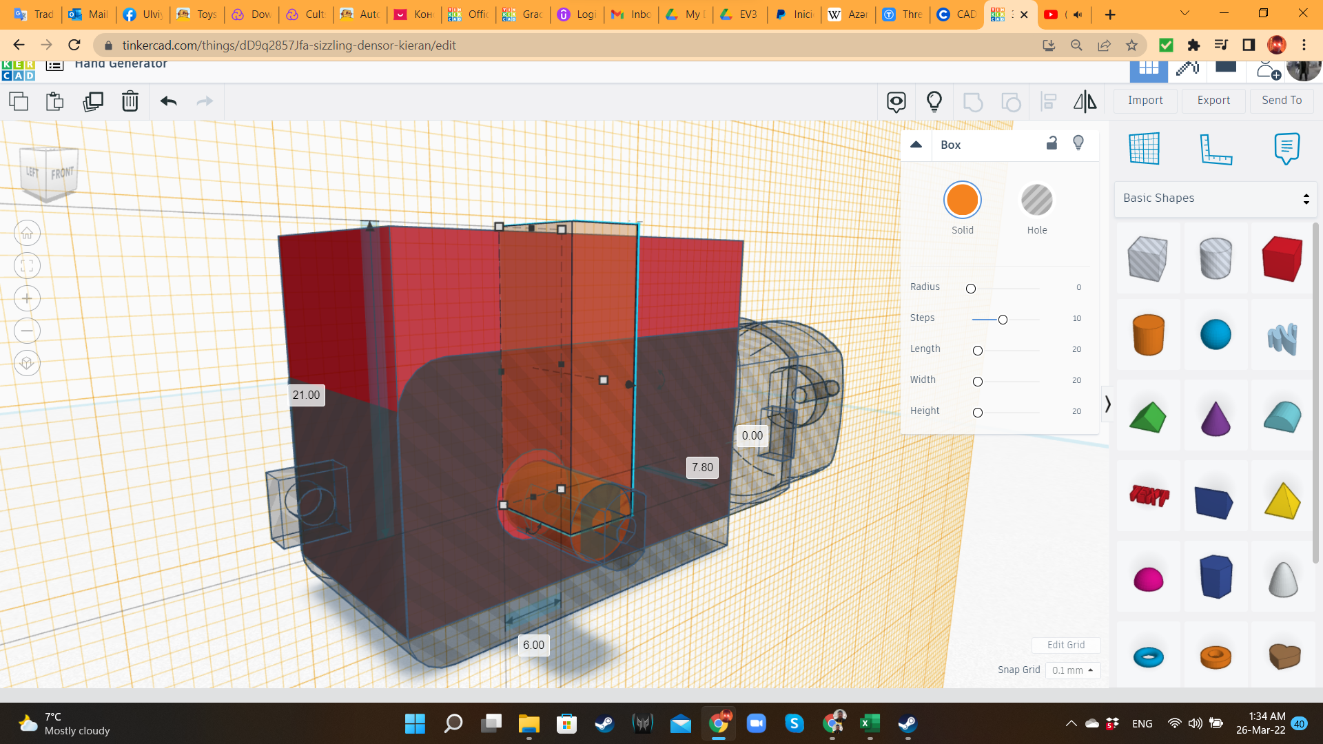
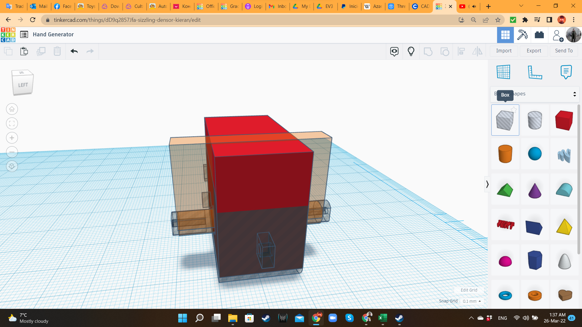
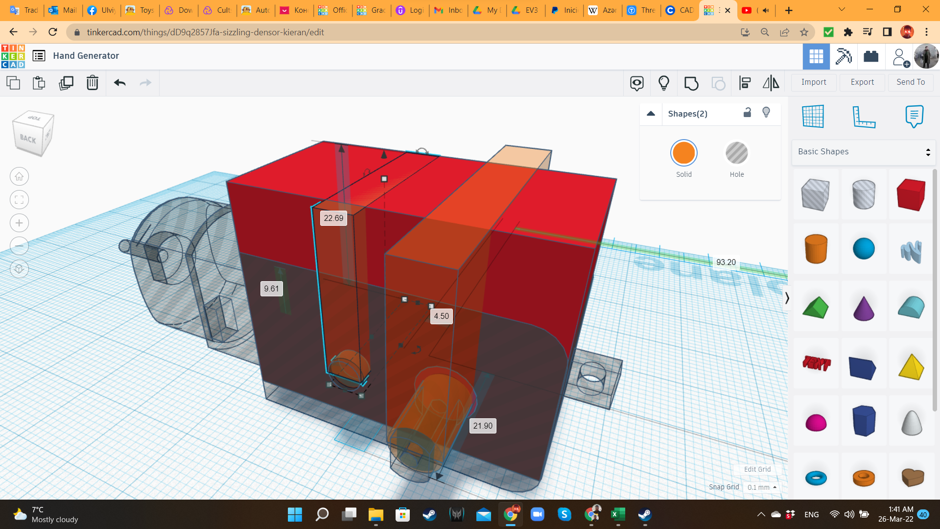
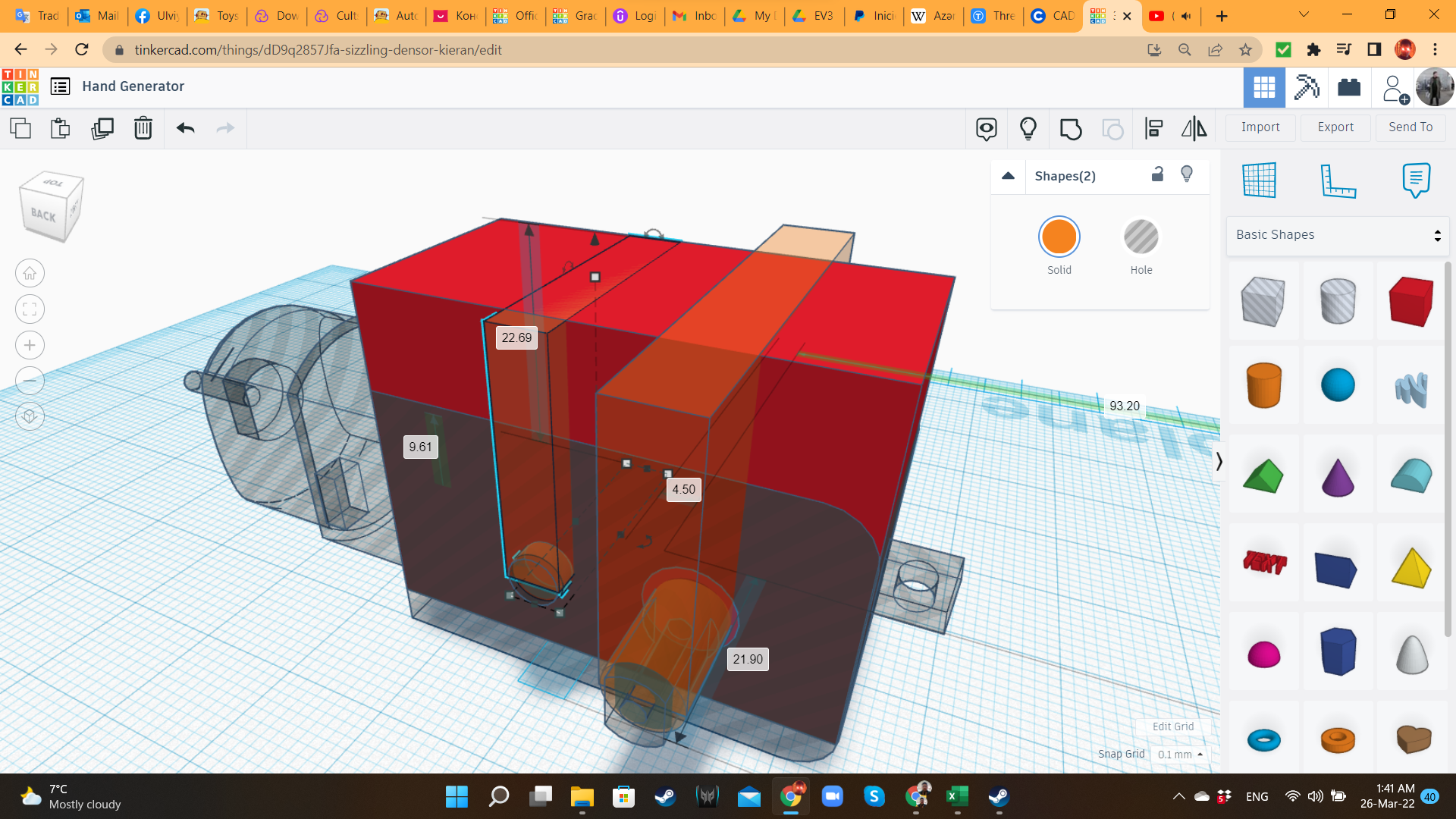
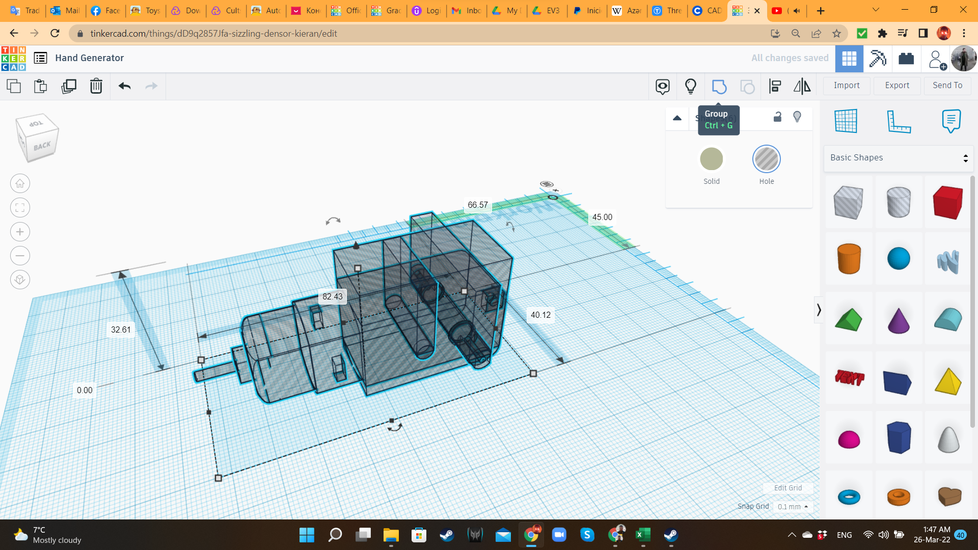
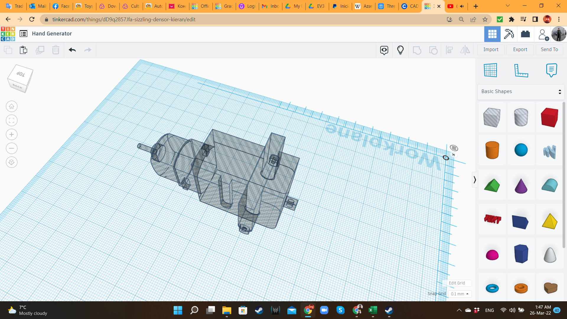
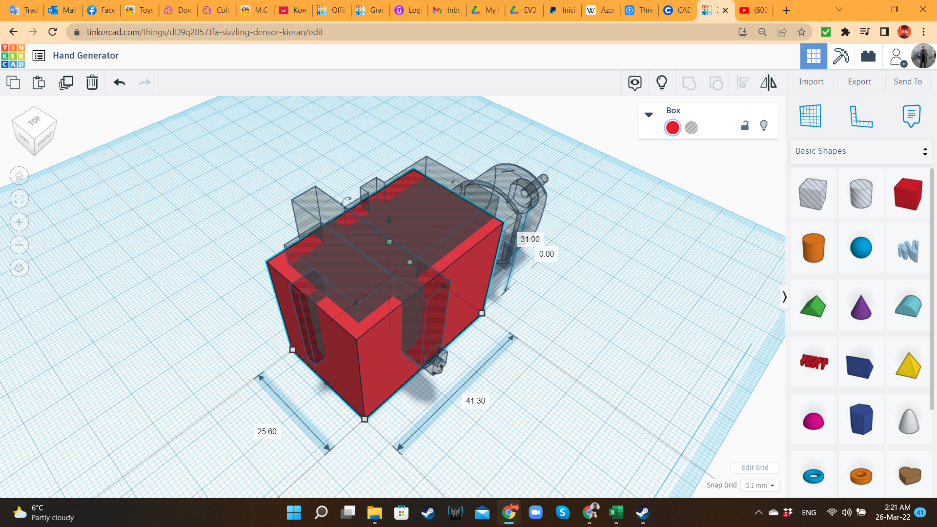
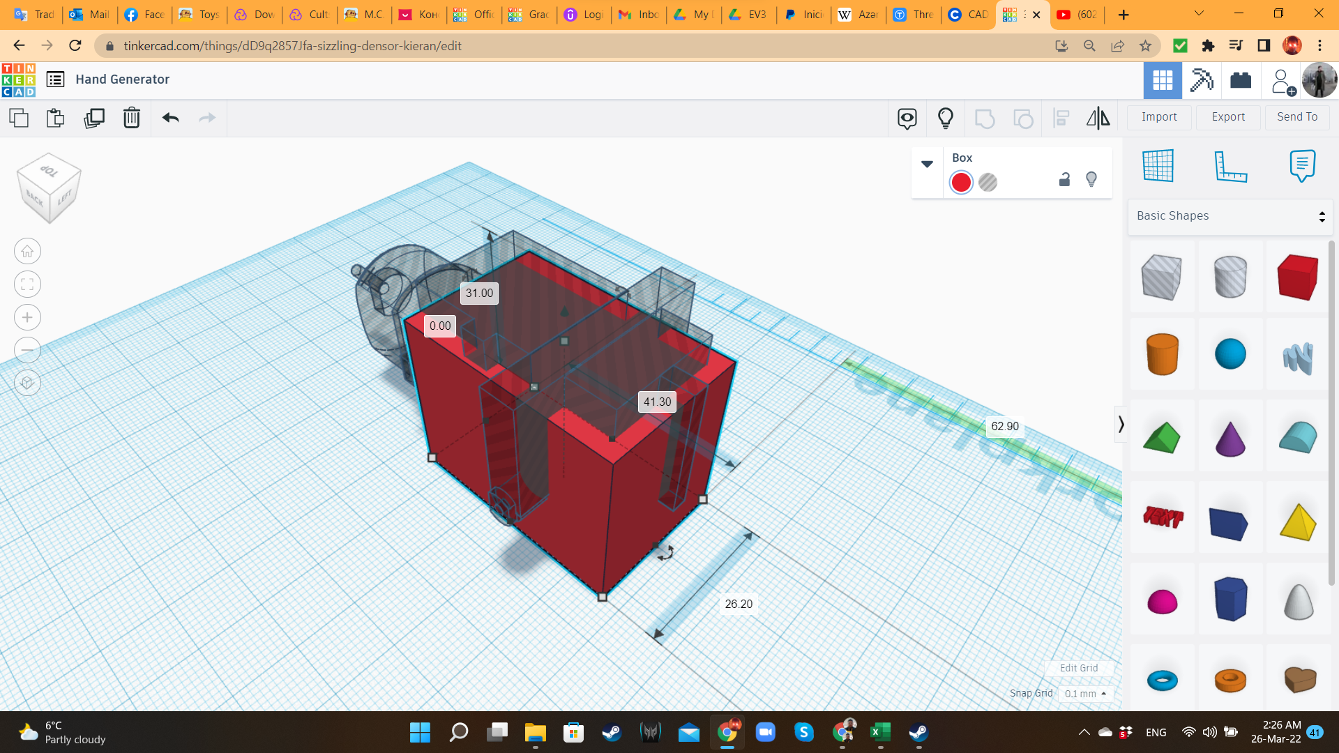
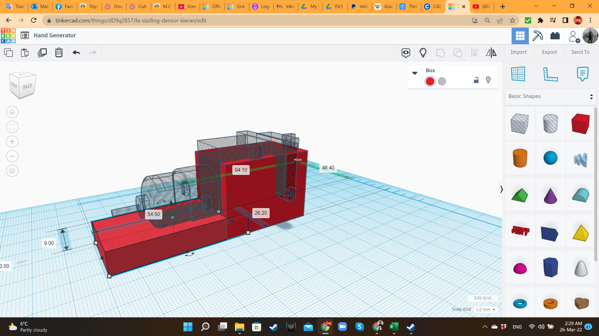
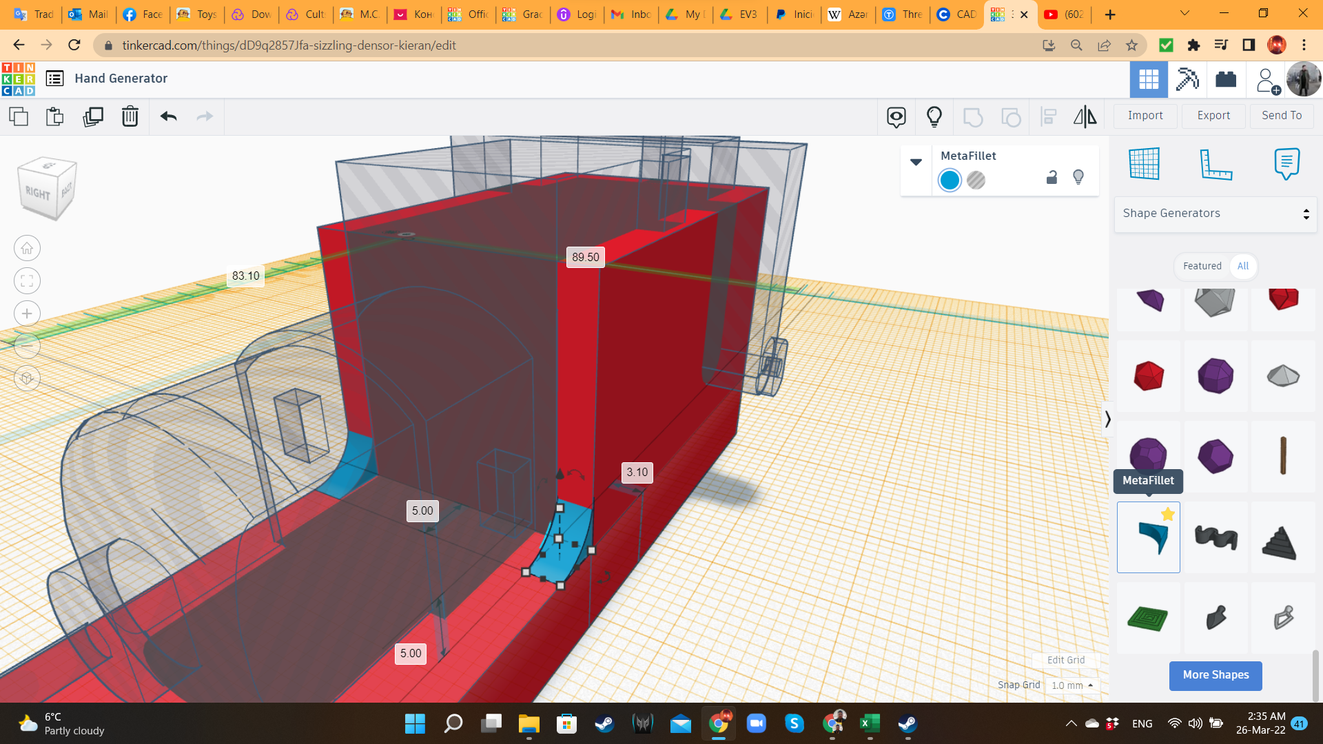
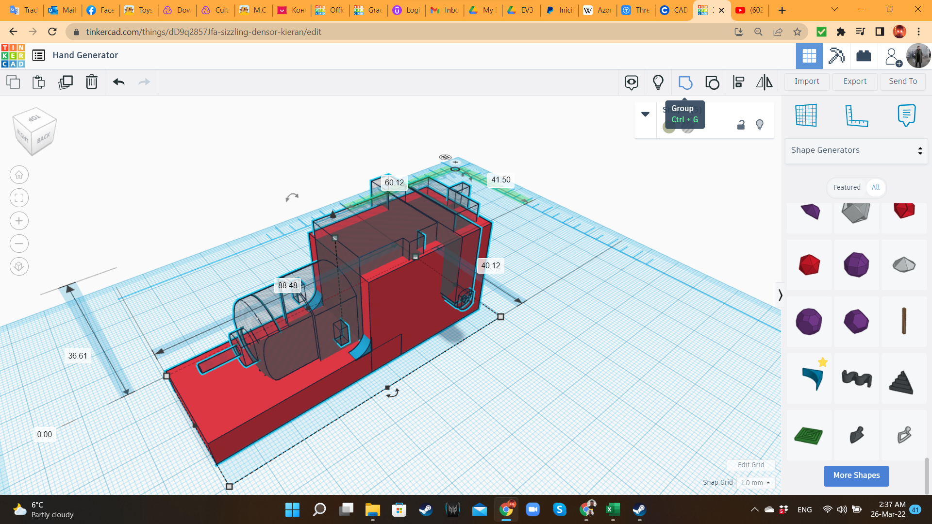
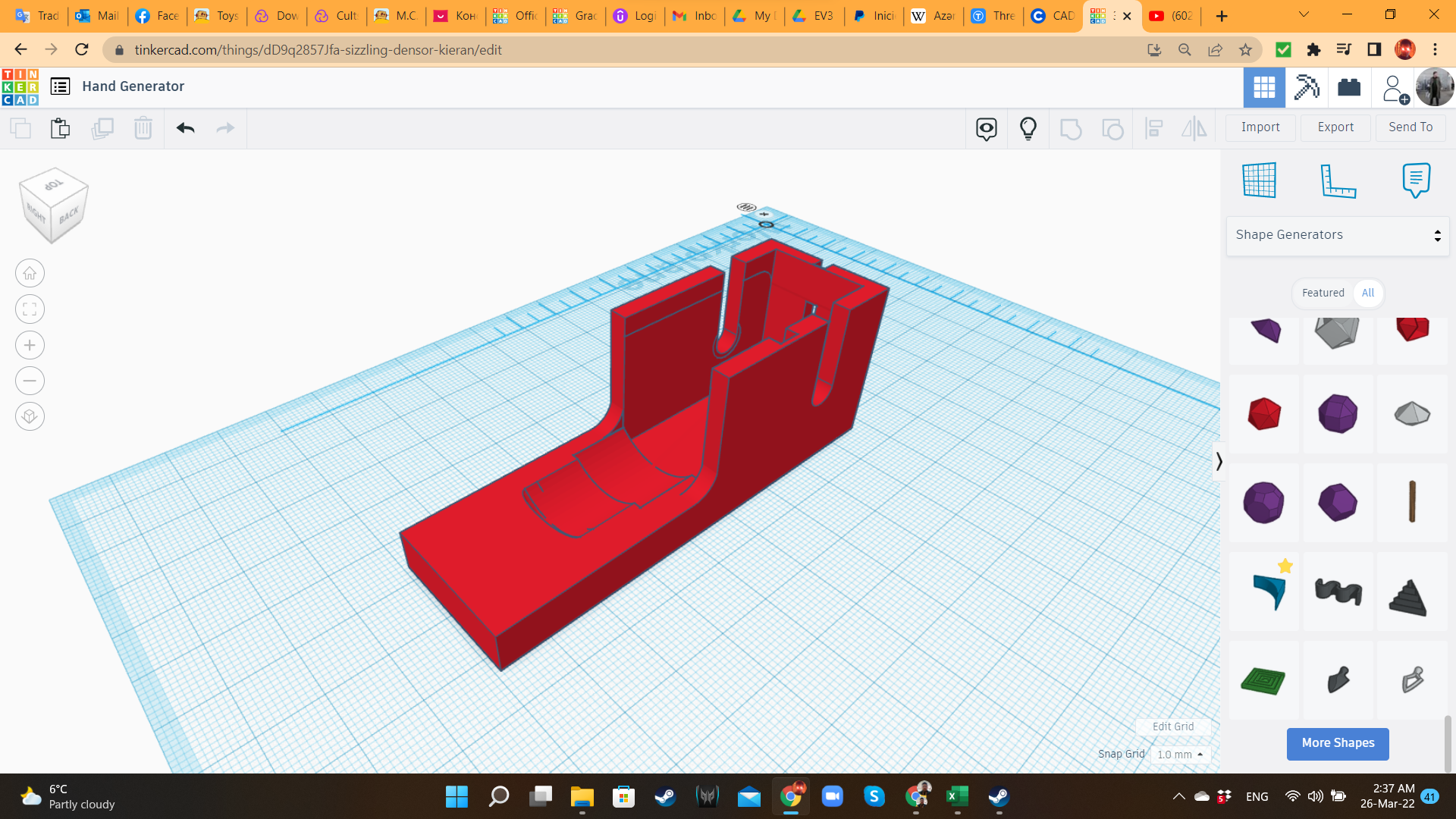
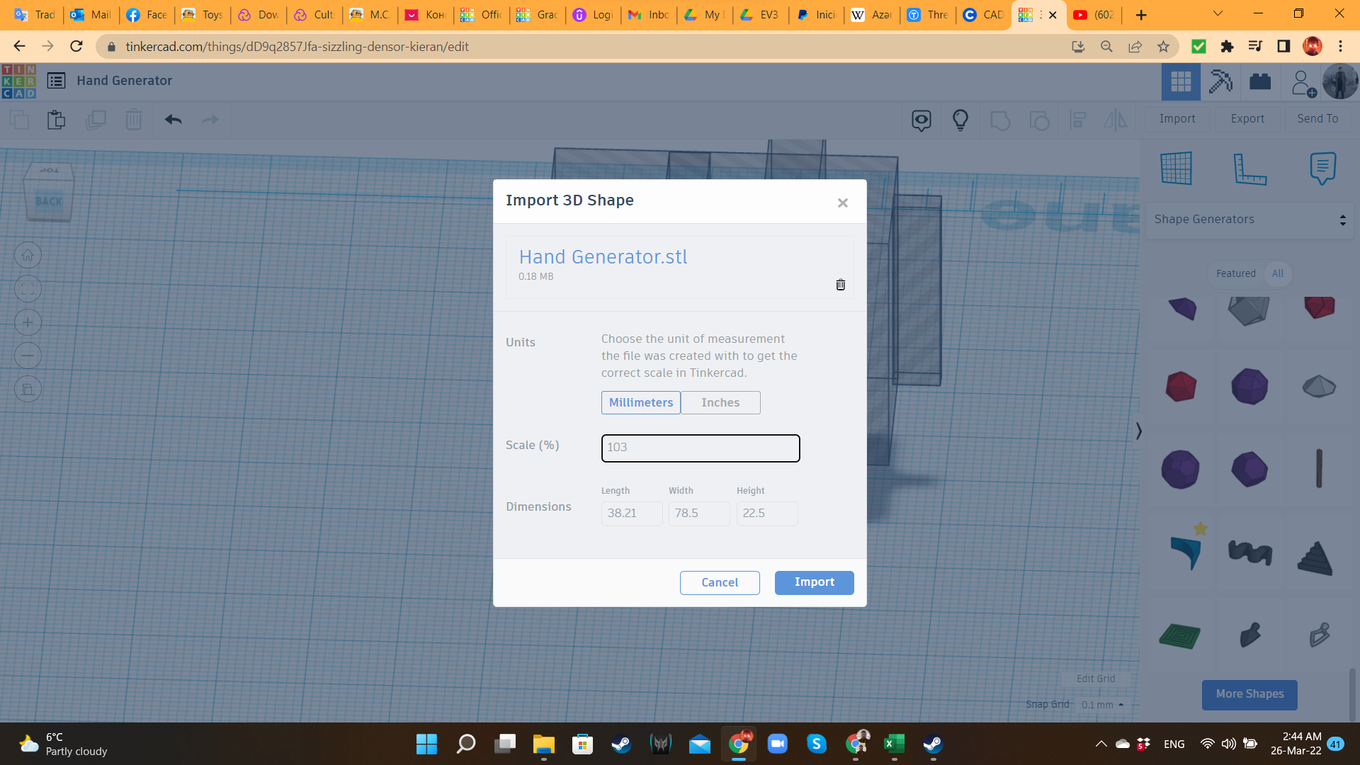
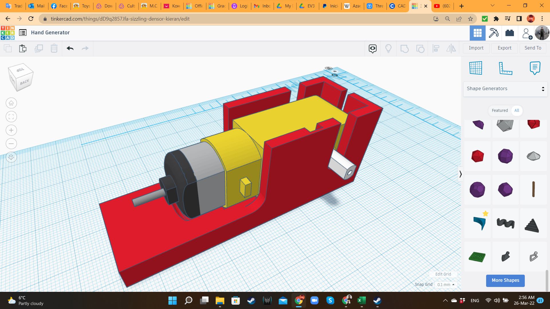
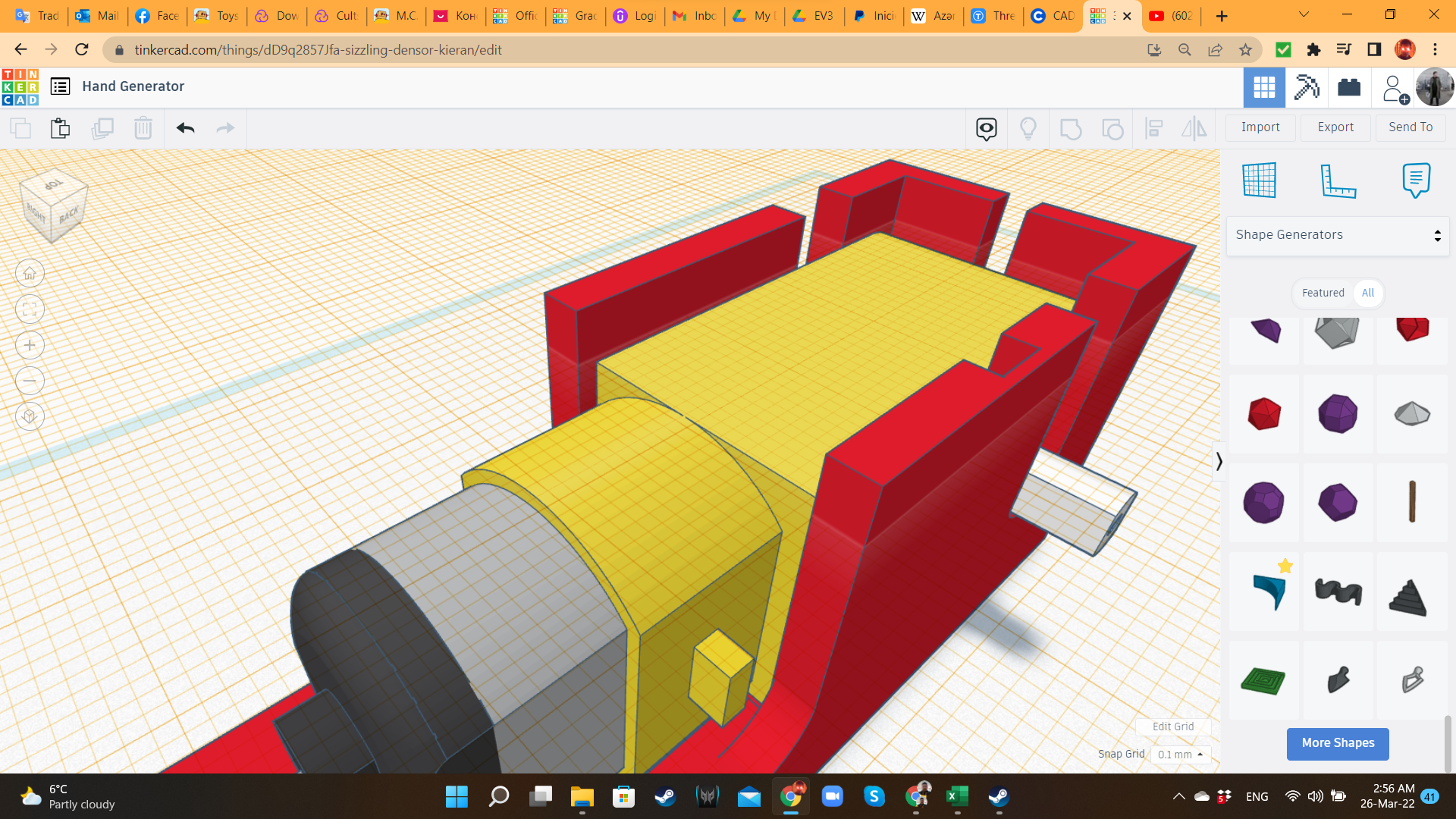
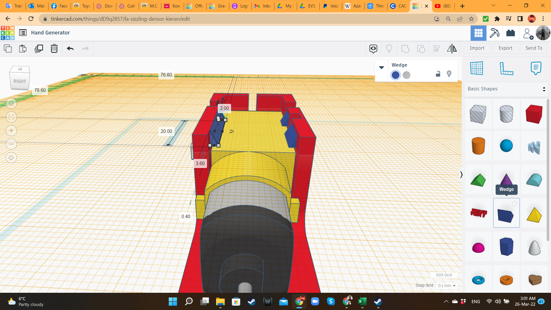
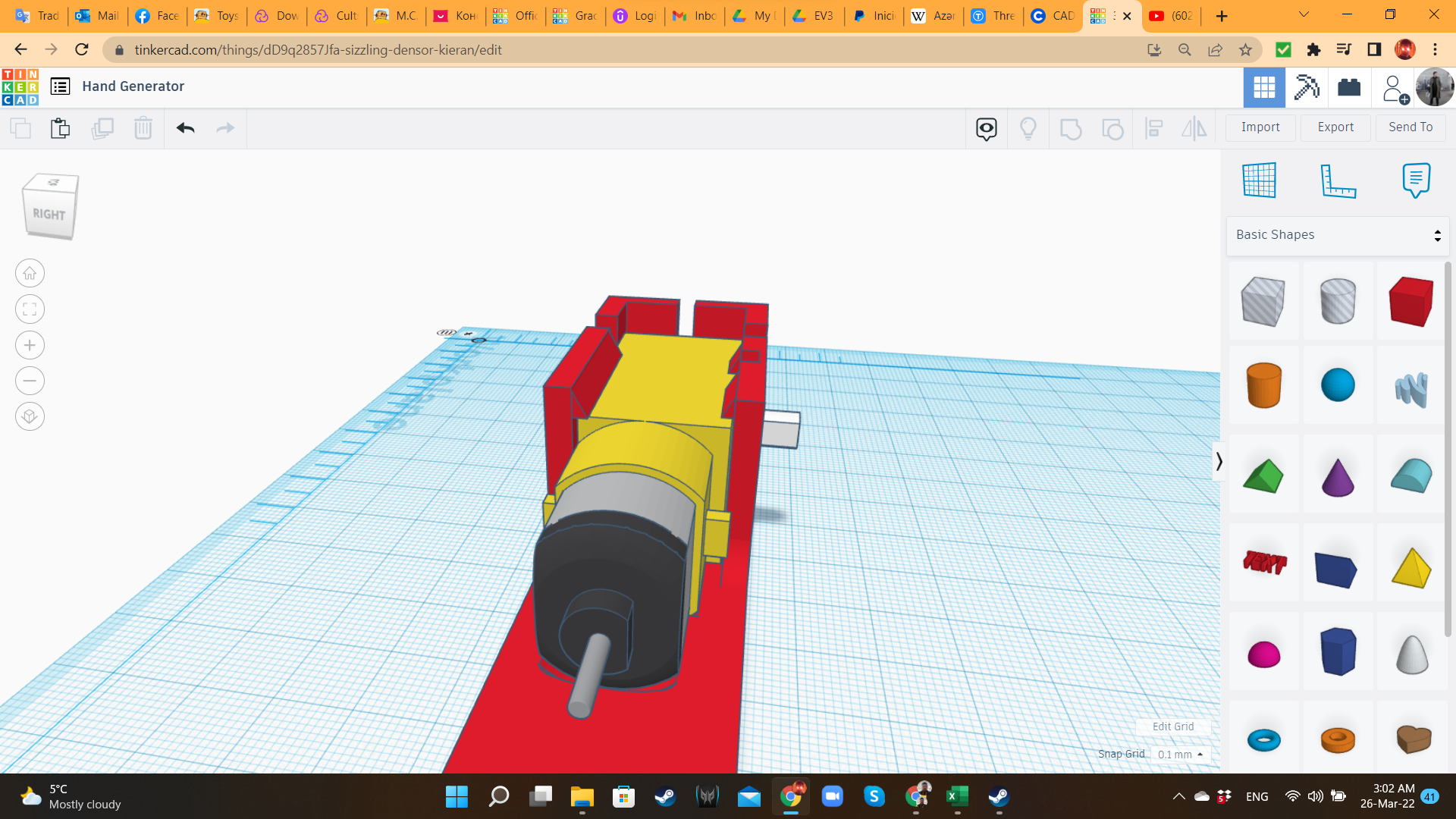
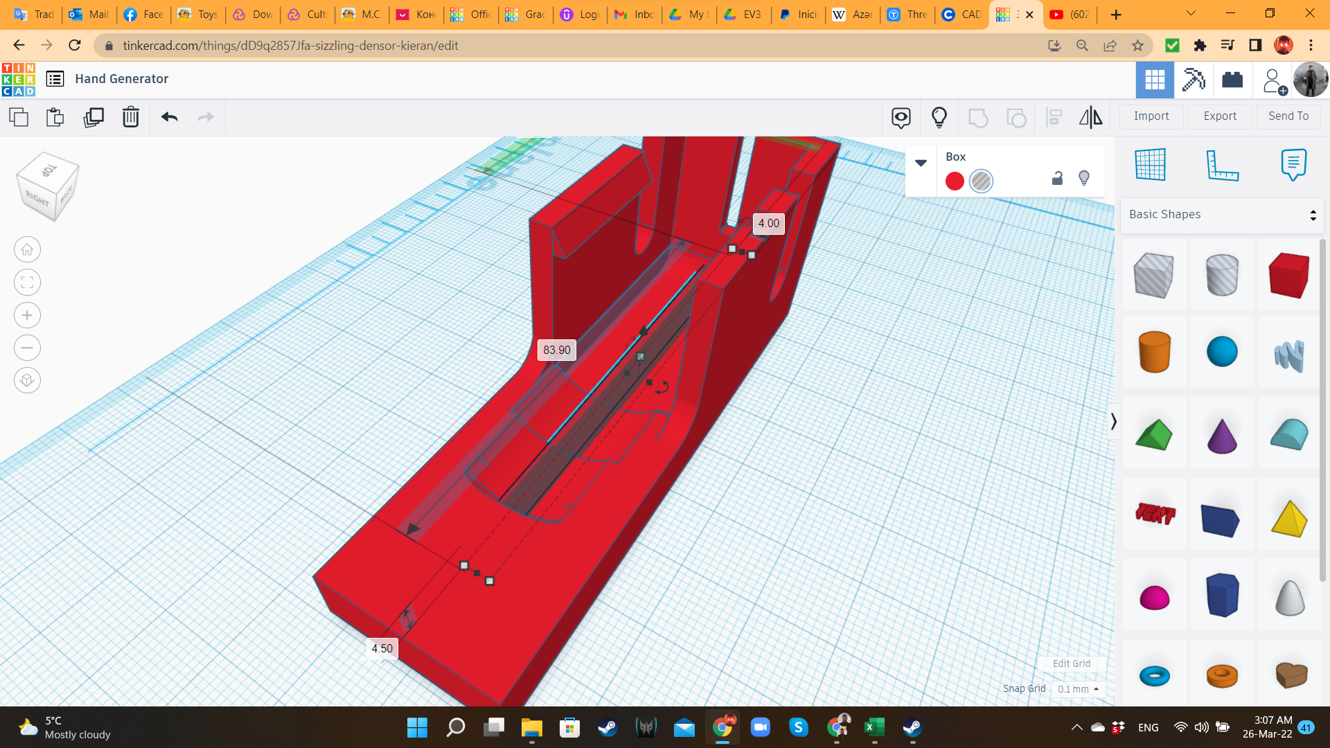
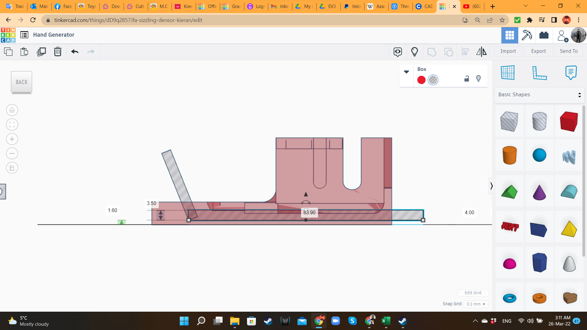
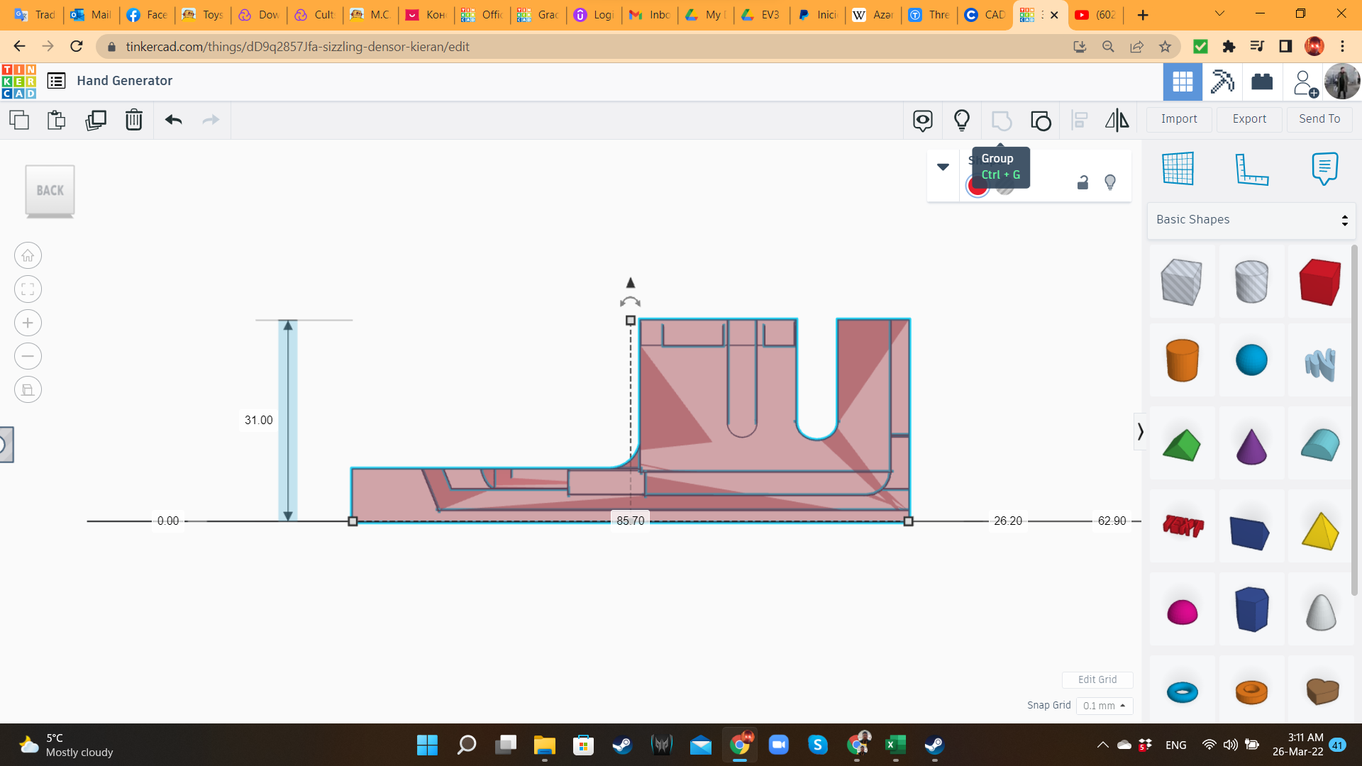
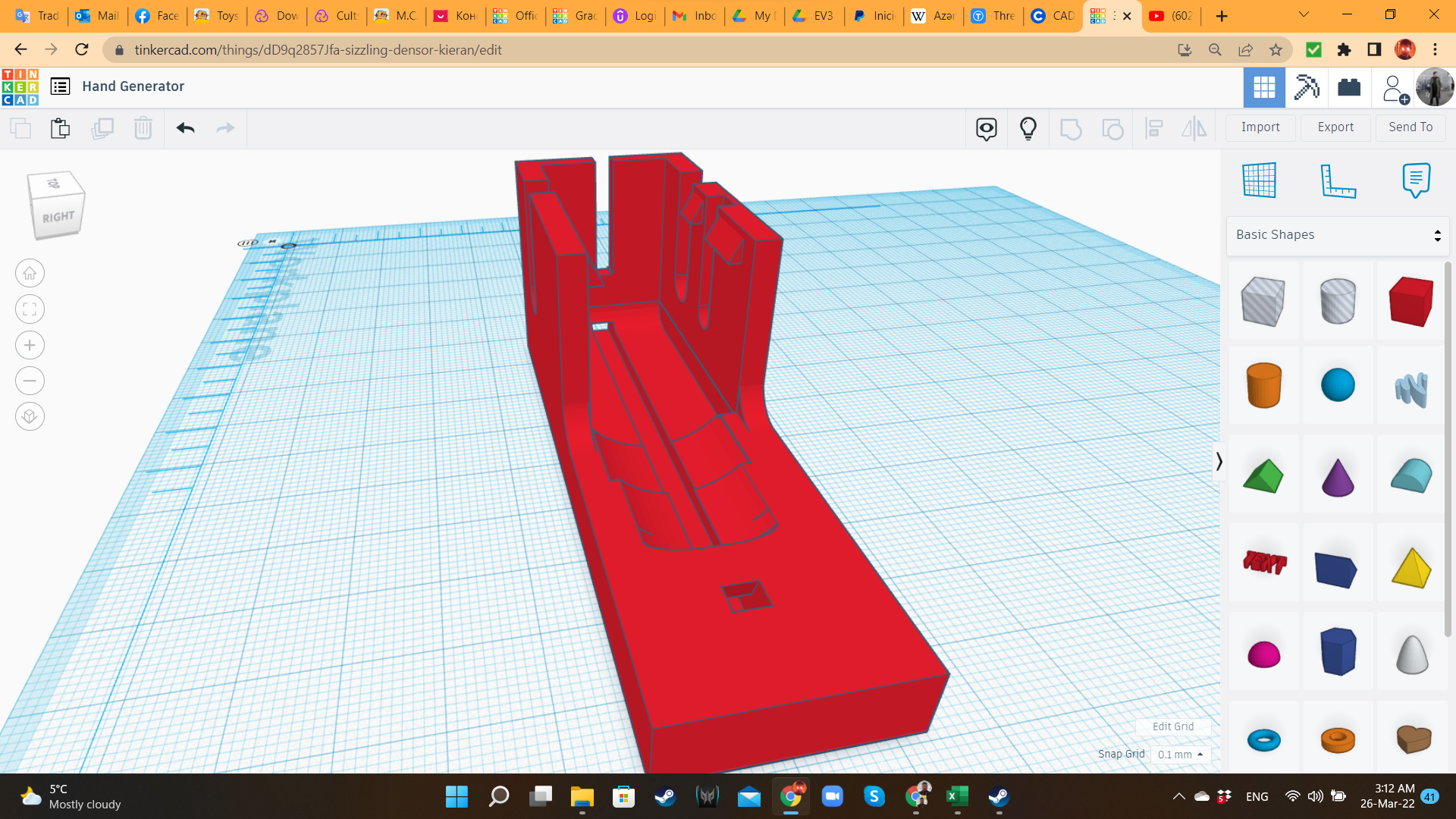
First, I brought a Hobby Gearmotor from the "Electronics" library, exported it as STL, and imported it back with a 105% scale, and transformed it into a hole, to create the perfect fit to house the real gearmotor. Then, I placed it in a Box from the "Basic Shapes" library. I added another box, with a lower height, to cover all the length of the gearbox. I also added other hole boxes for the protruding parts of the gearbox. Then, I grouped all the holes to the solid boxes, creating the housing for the gearmotor.
On top of the walls (that from this moment I will call "tabs"), I added wedges ("Basic Shapes" library), so the gearbox can enter, but after that, it will get trapped inside.
I also added a "tunnel" on bottom, where the cable would be inserted.
Hand Dynamo 2: Handle
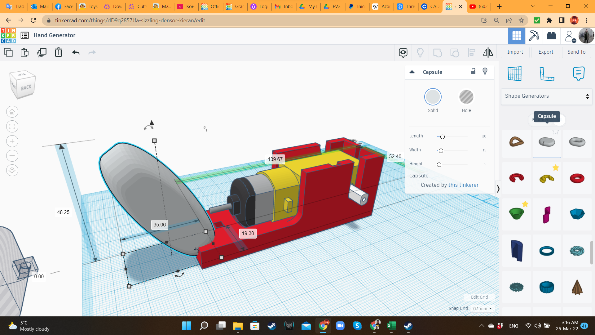
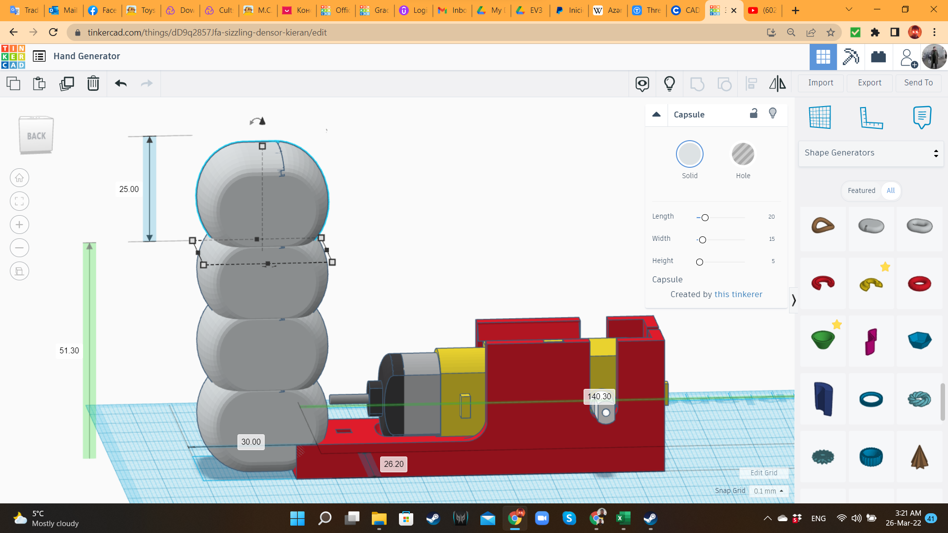
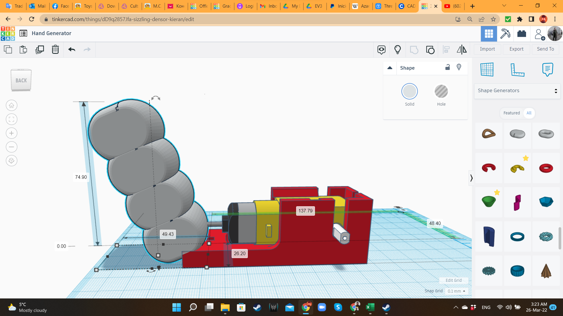
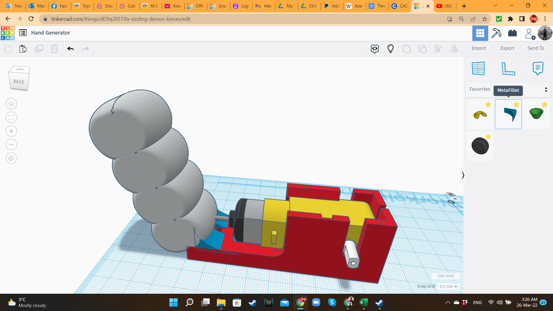
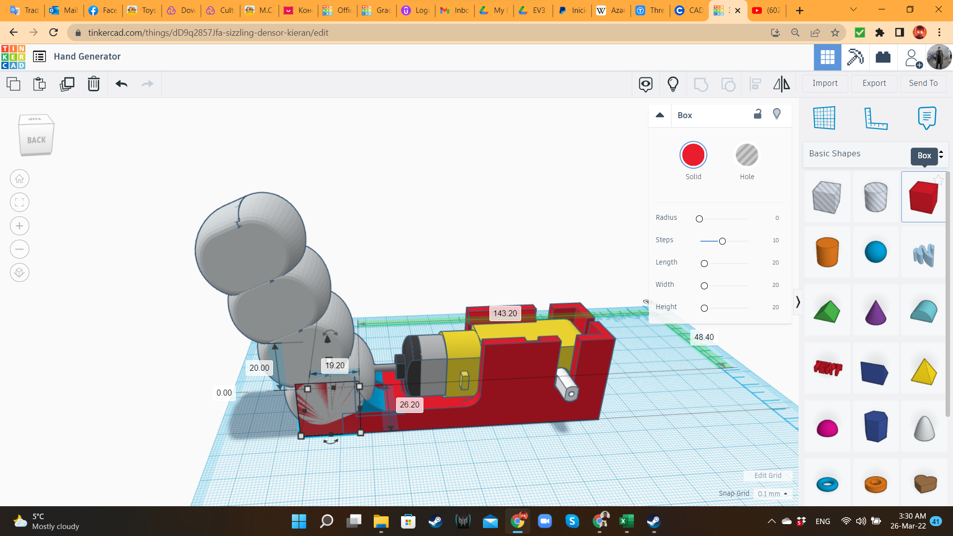
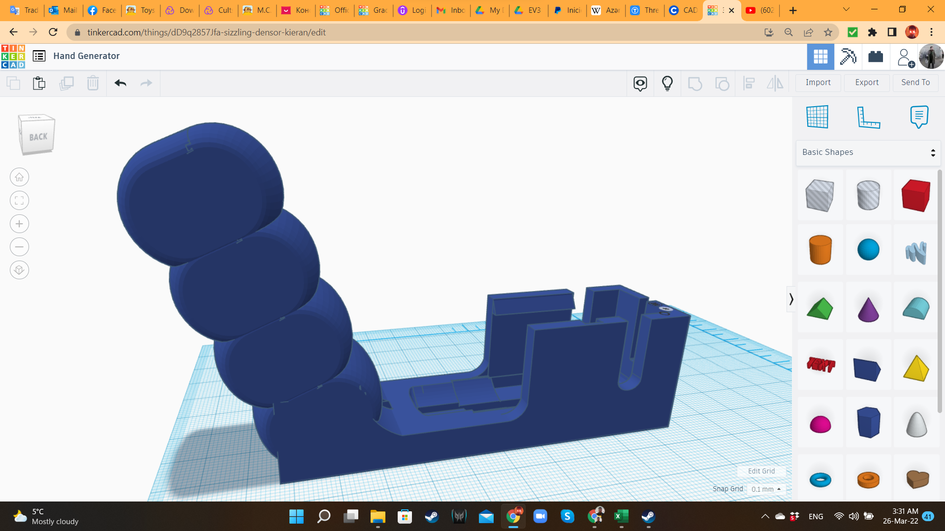
Using Capsules and Metafillets (from "Shape Generators/All" library), I created the handle, giving the shape of a gun's handle.
Hand Dynamo 3: Crank
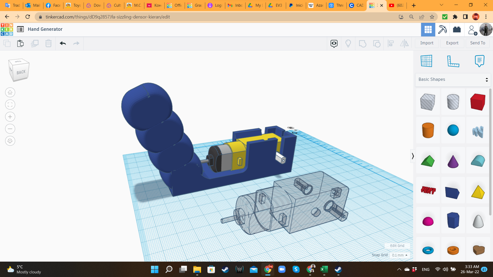
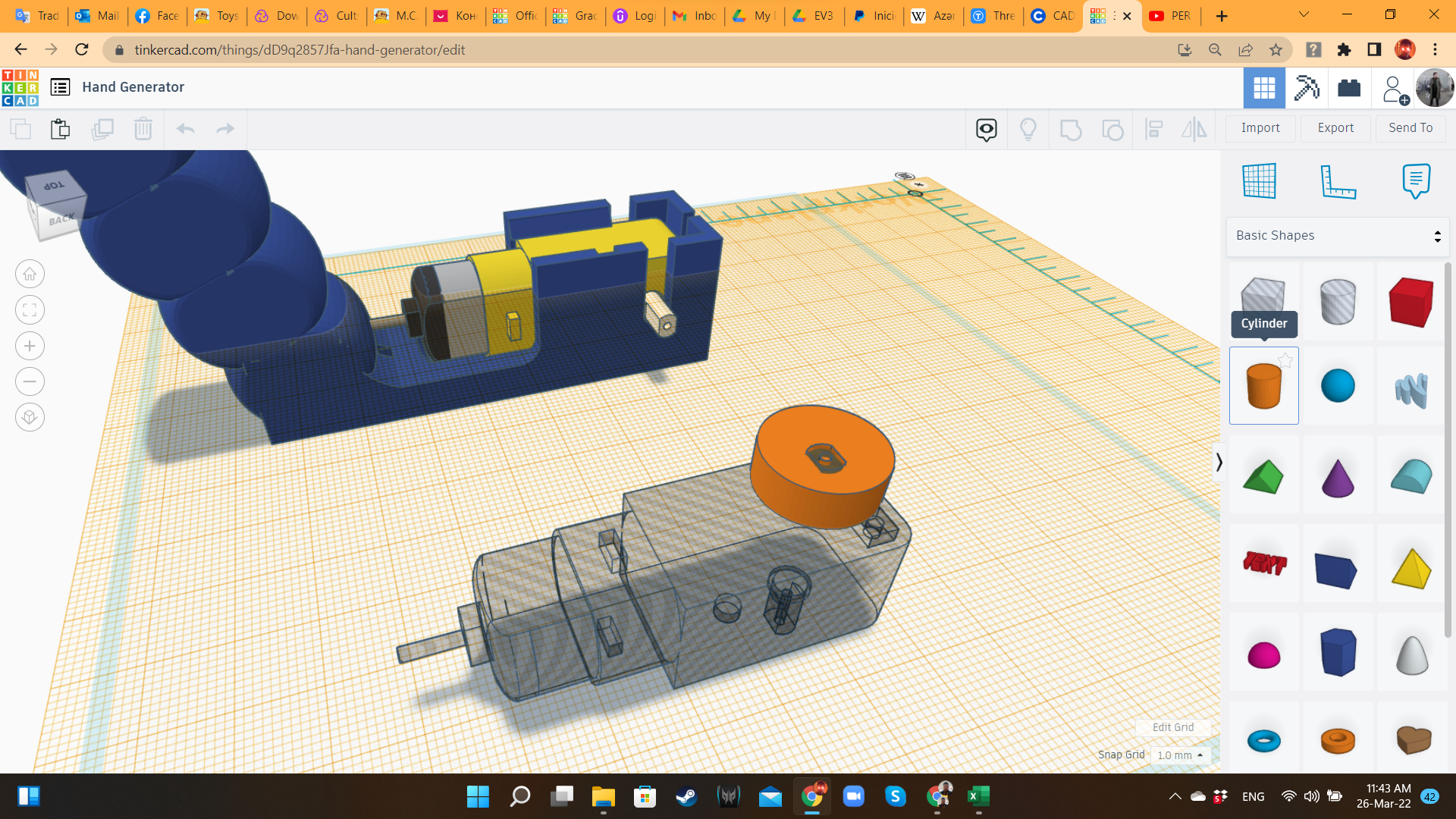
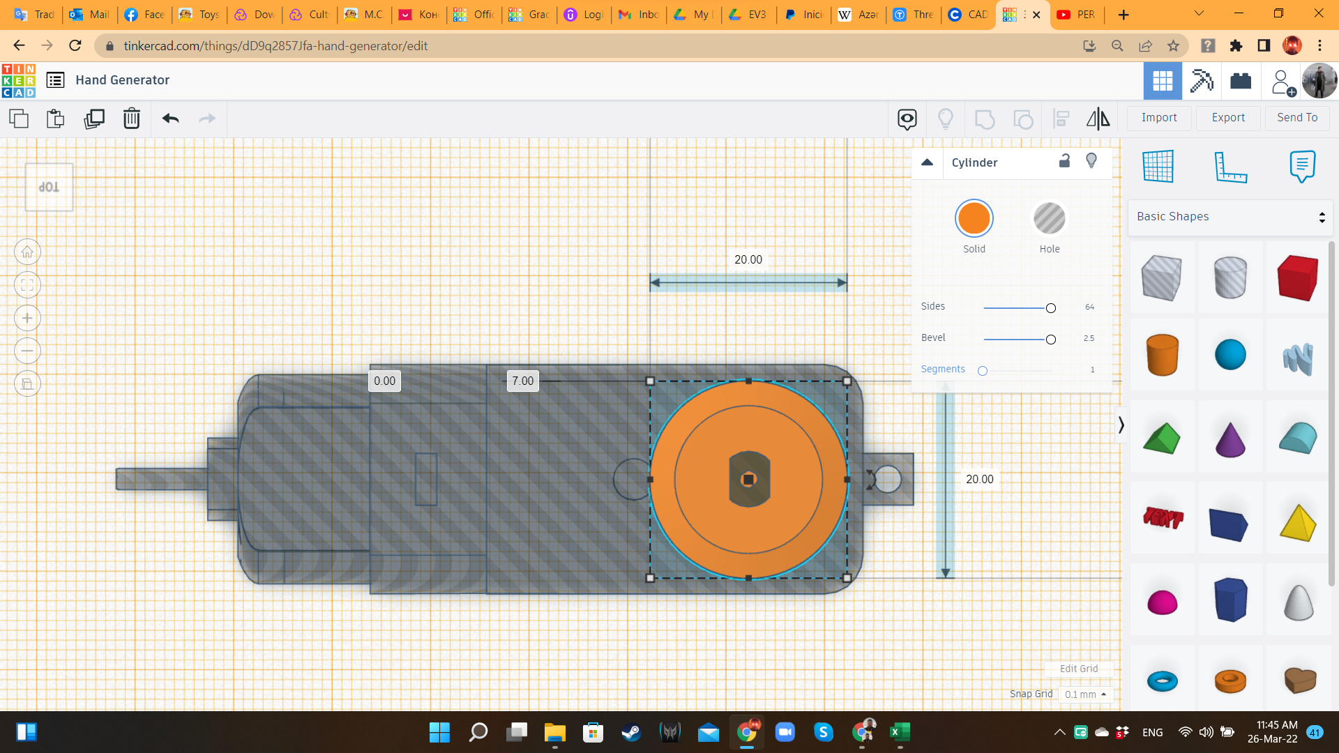
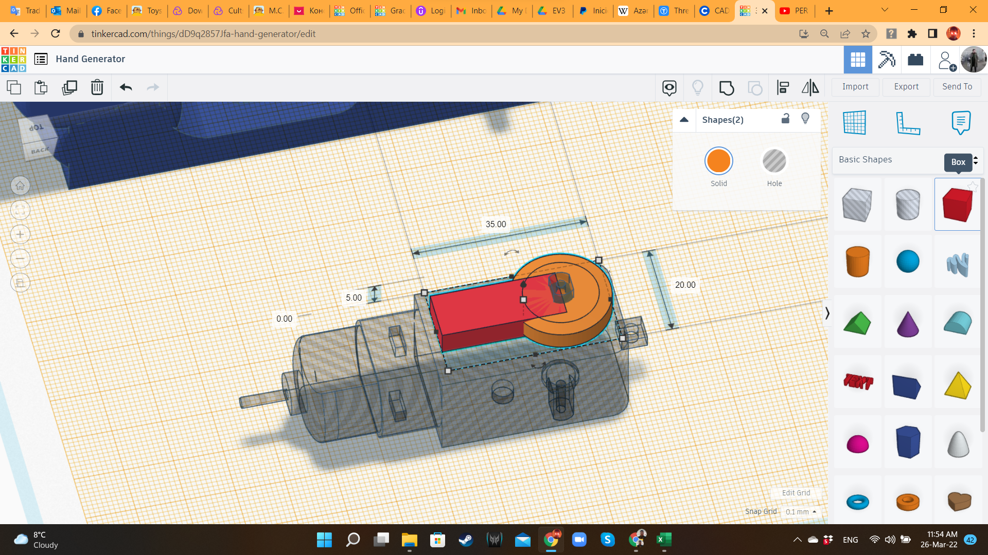
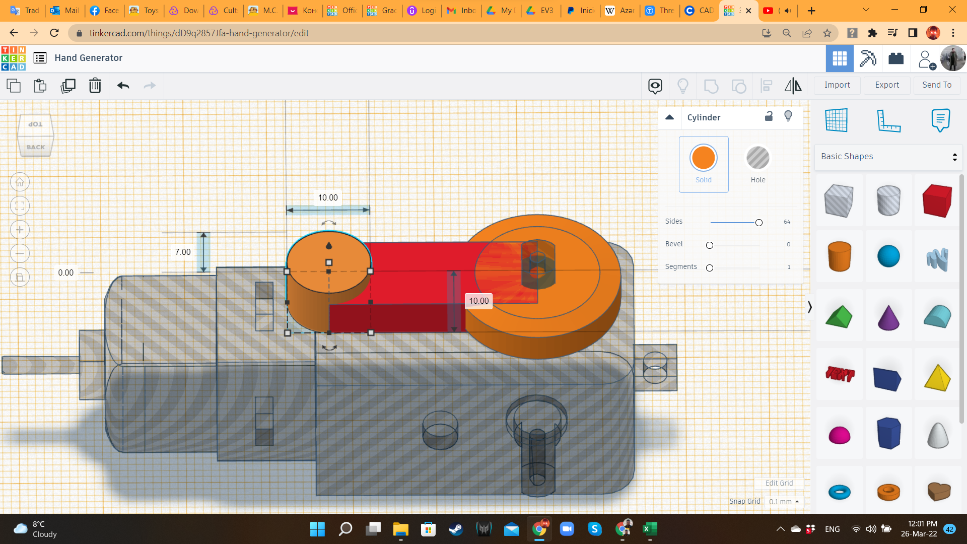
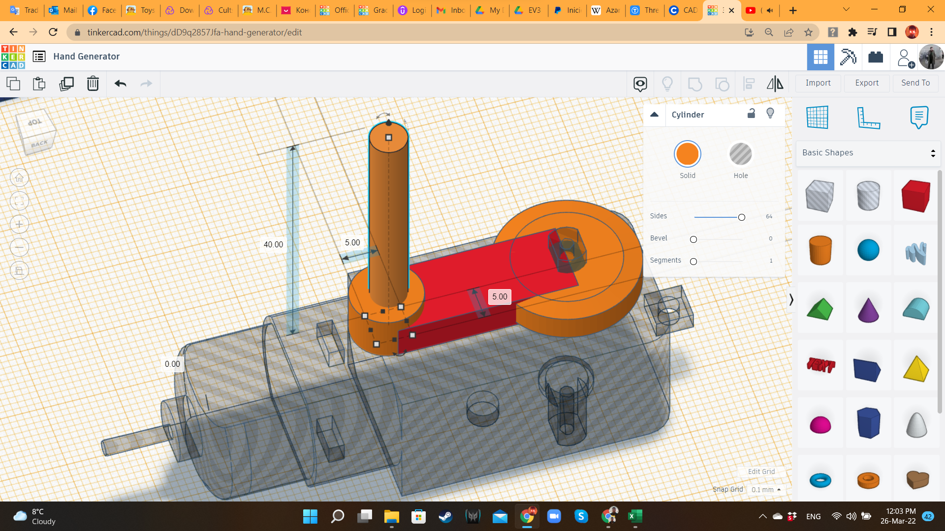
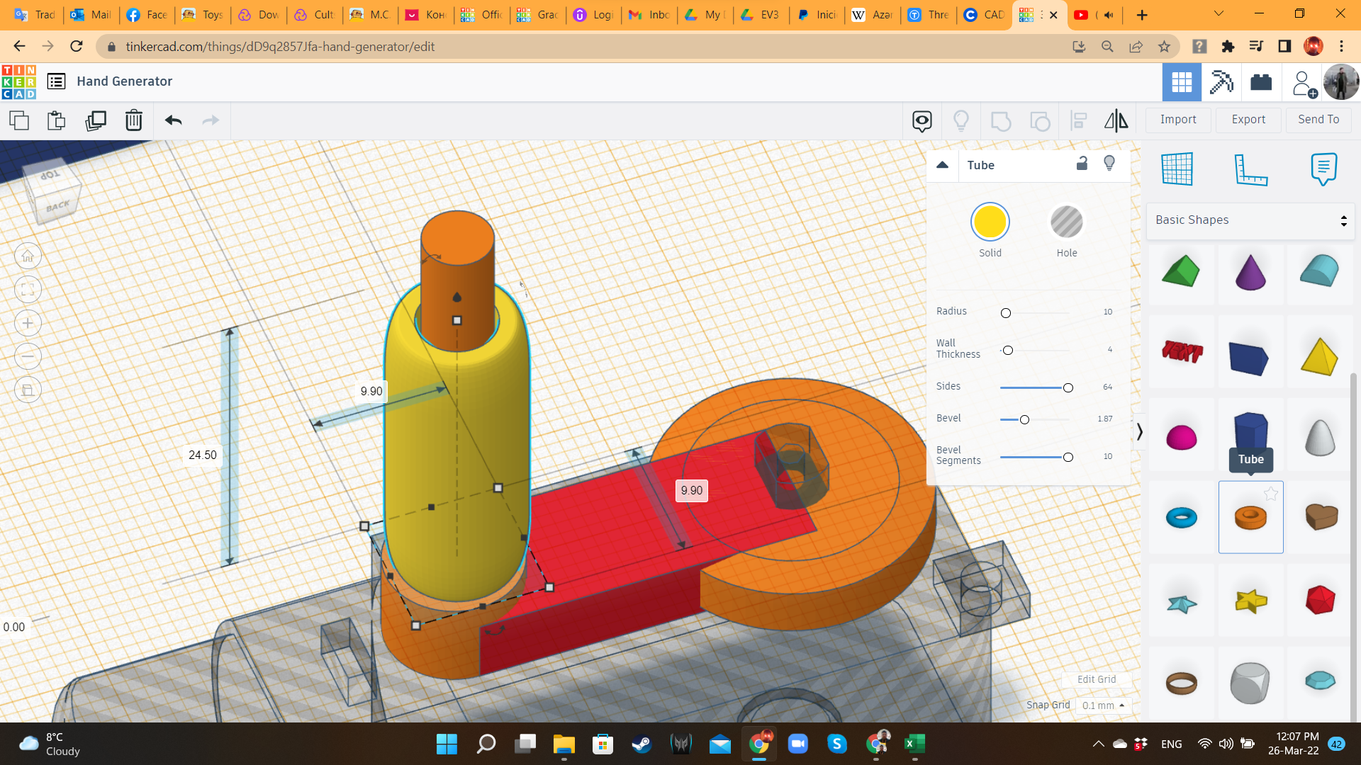
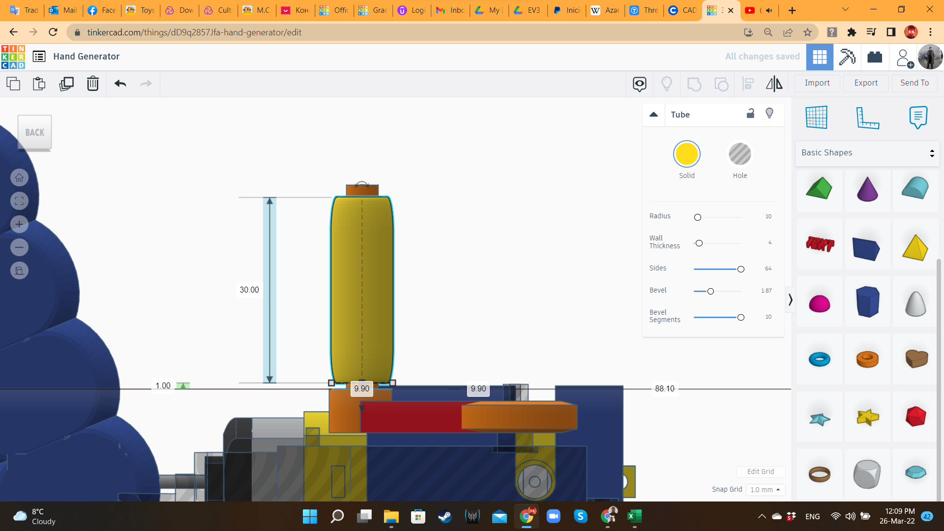
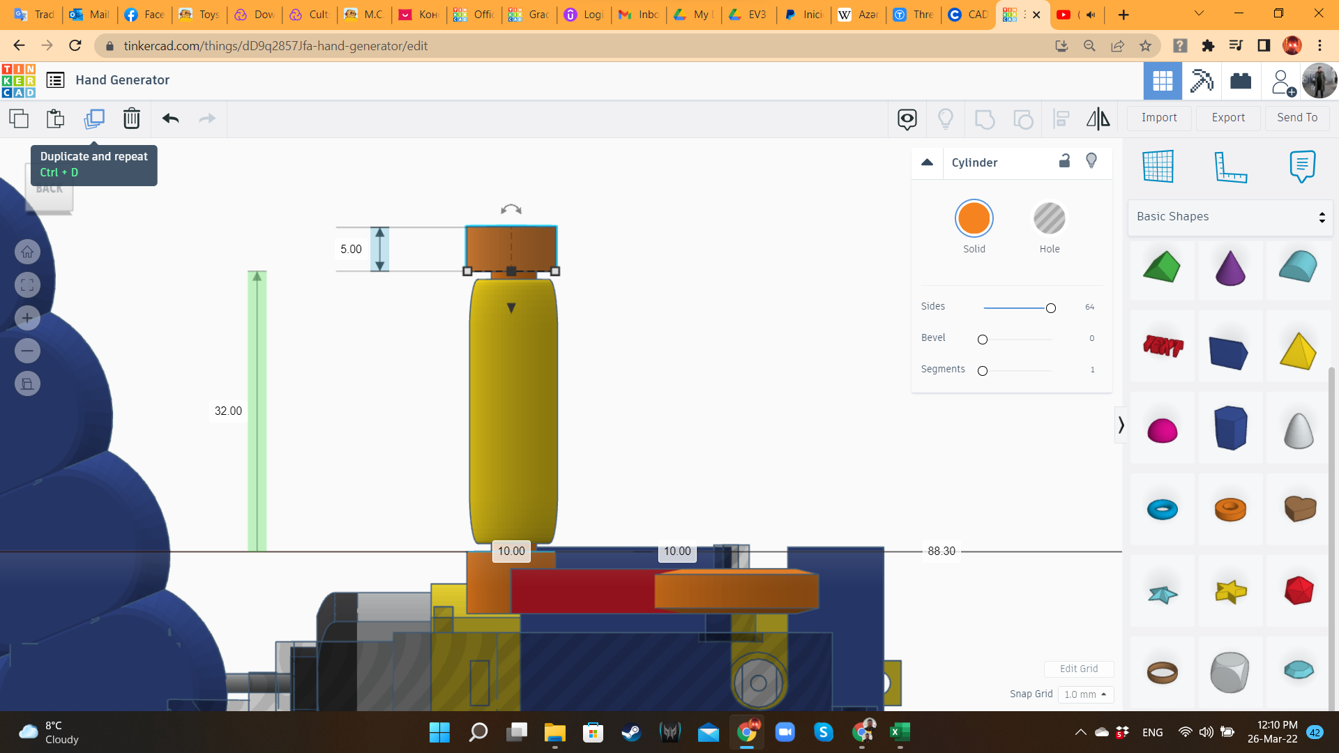
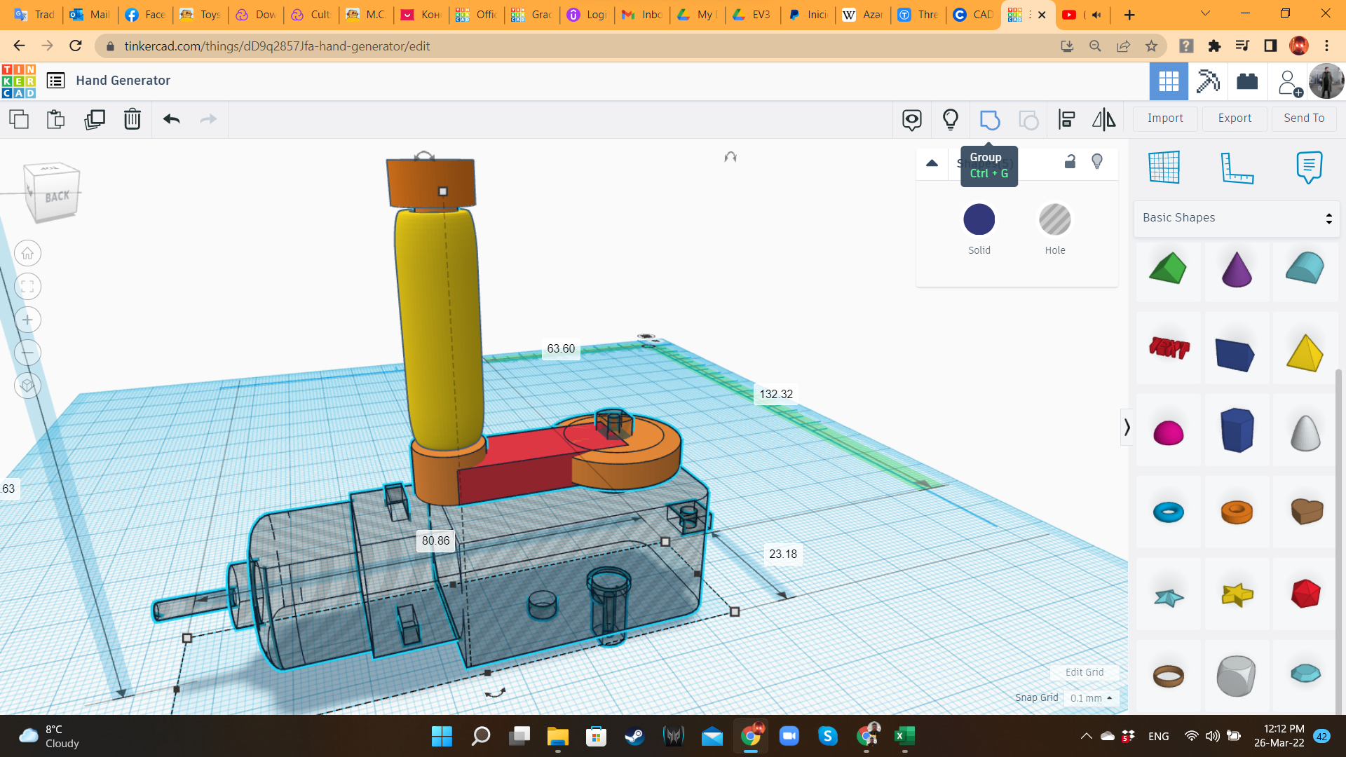
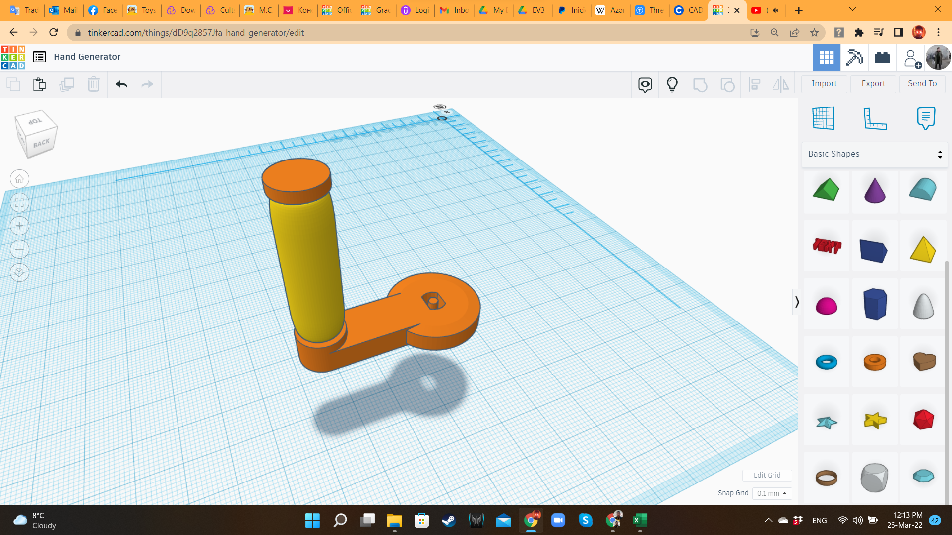
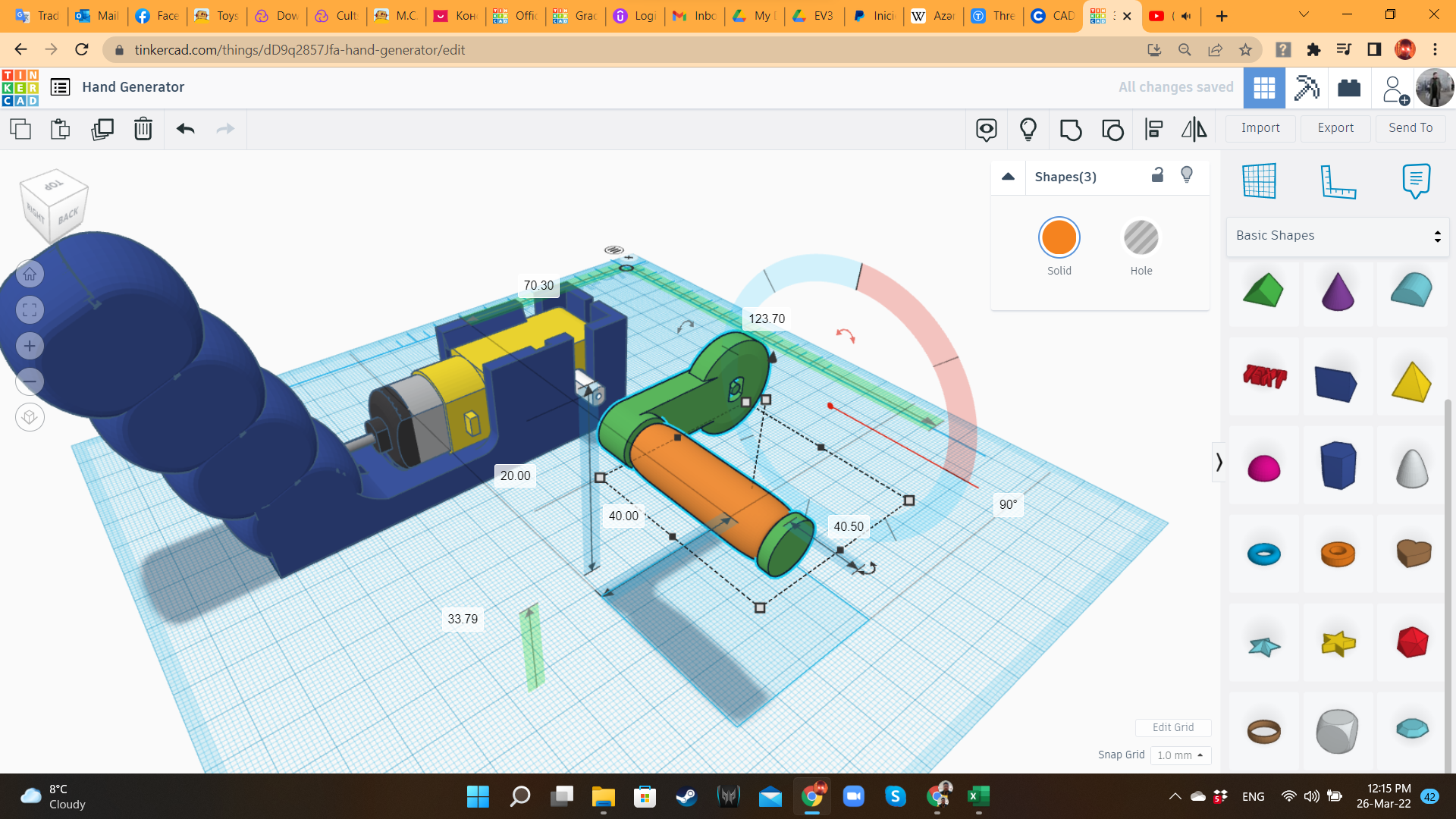
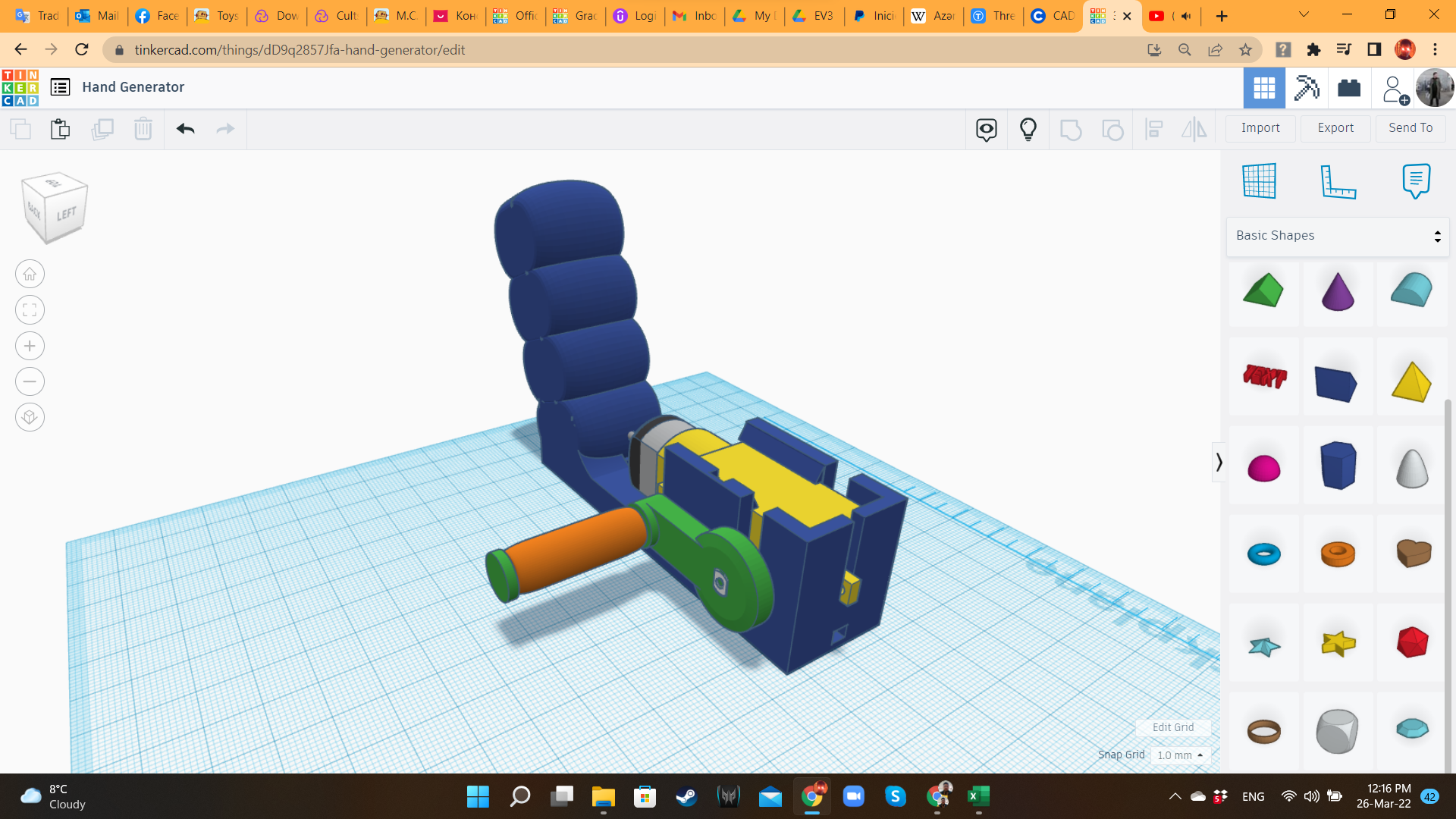
To create the crank, I imported again a Hobby Gearmotor STL at 105% scale, and placed the axle in the center of a flat cylinder ("Basic Shapes" library), so it can fir perfectly the real gearbox. I grouped them. Then, I added a long Box, and some concentric cylinders. In the center of those cylinders, I placed a Tube from "Basic Shapes", so it can slide every time the crank is turned. The idea is to print this both components as a single piece. The Hand Dynamo design is ready! Or that was what I thought...
Hand Dynamo 4: Ergonomics
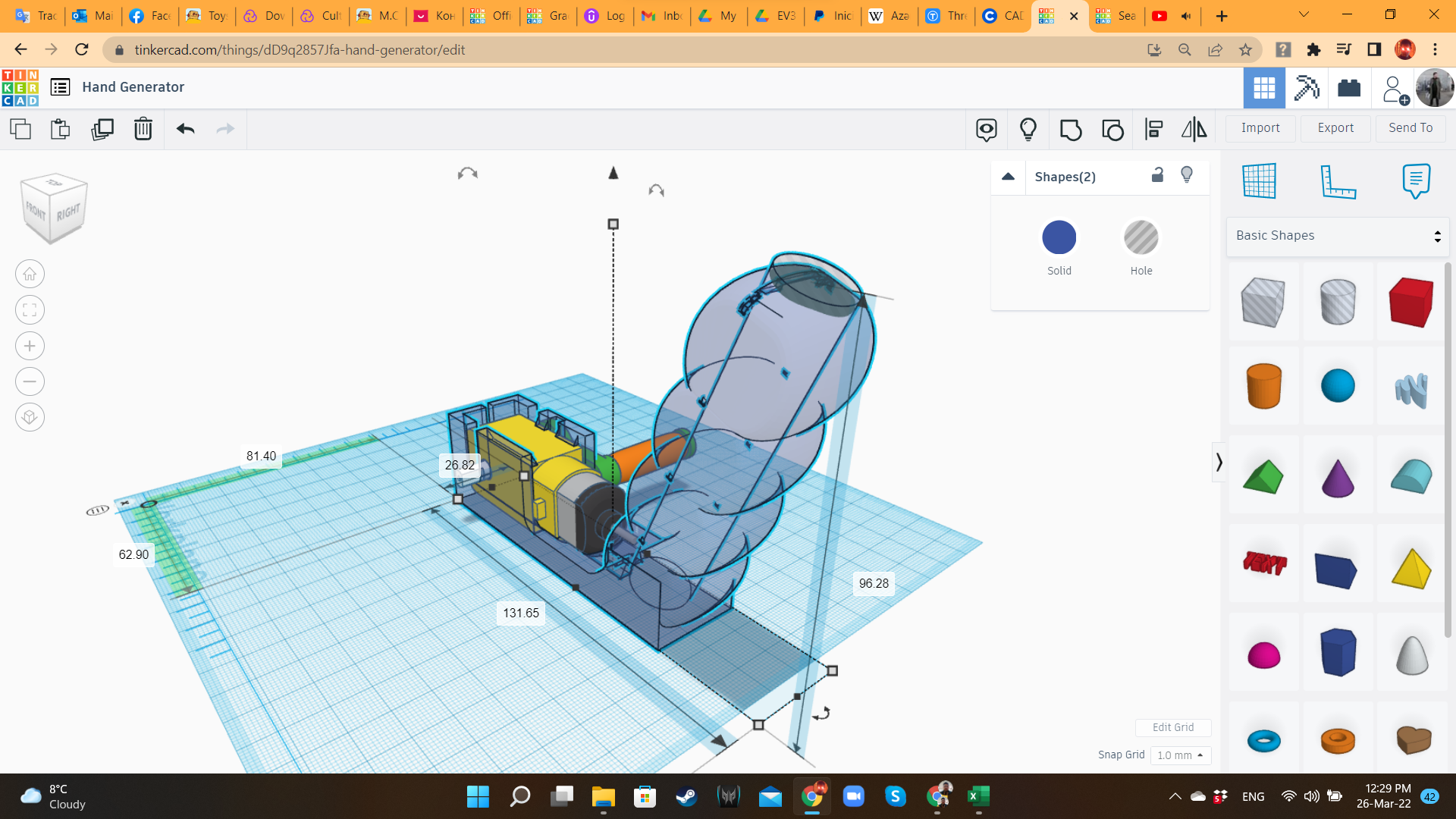
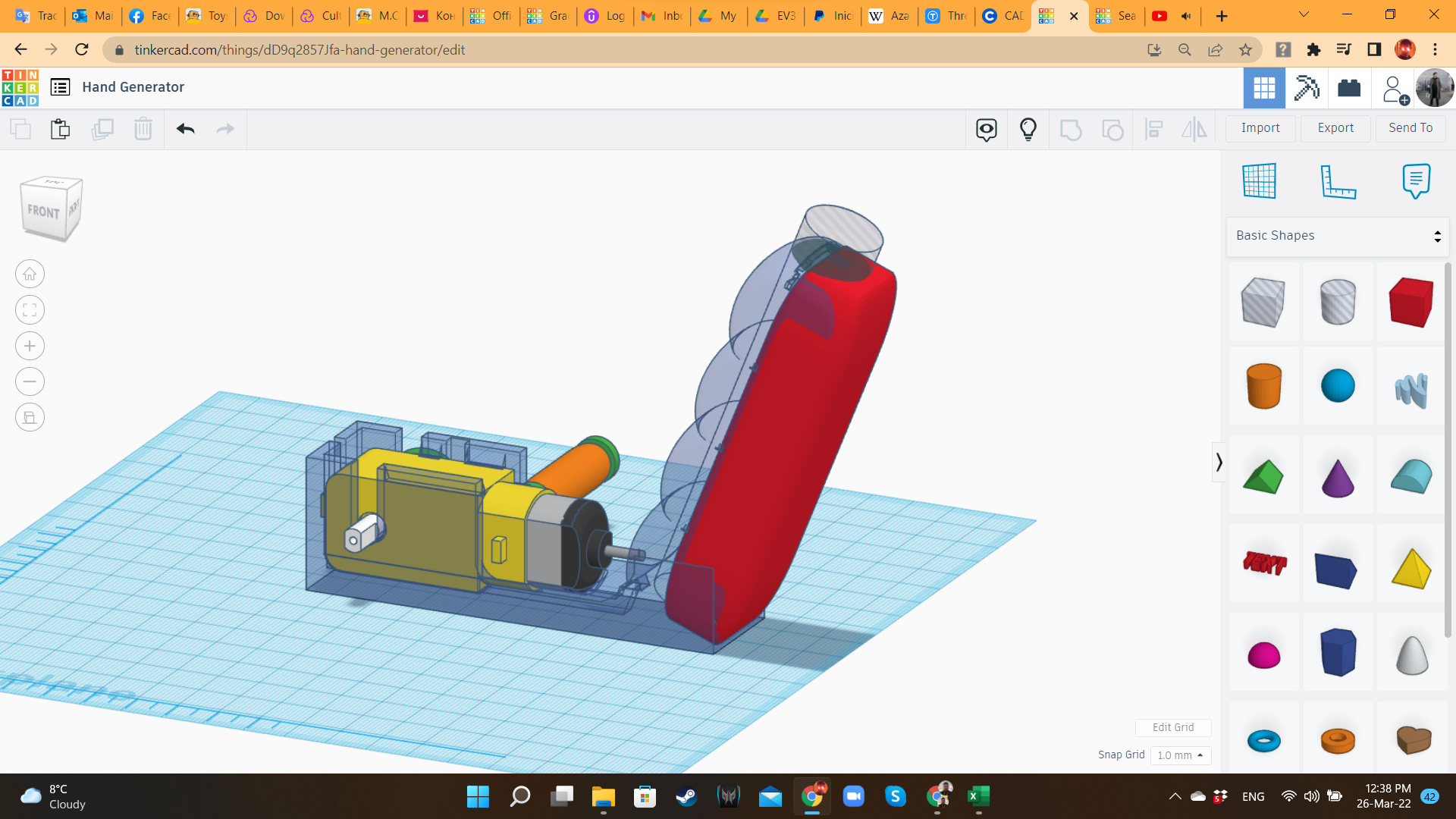
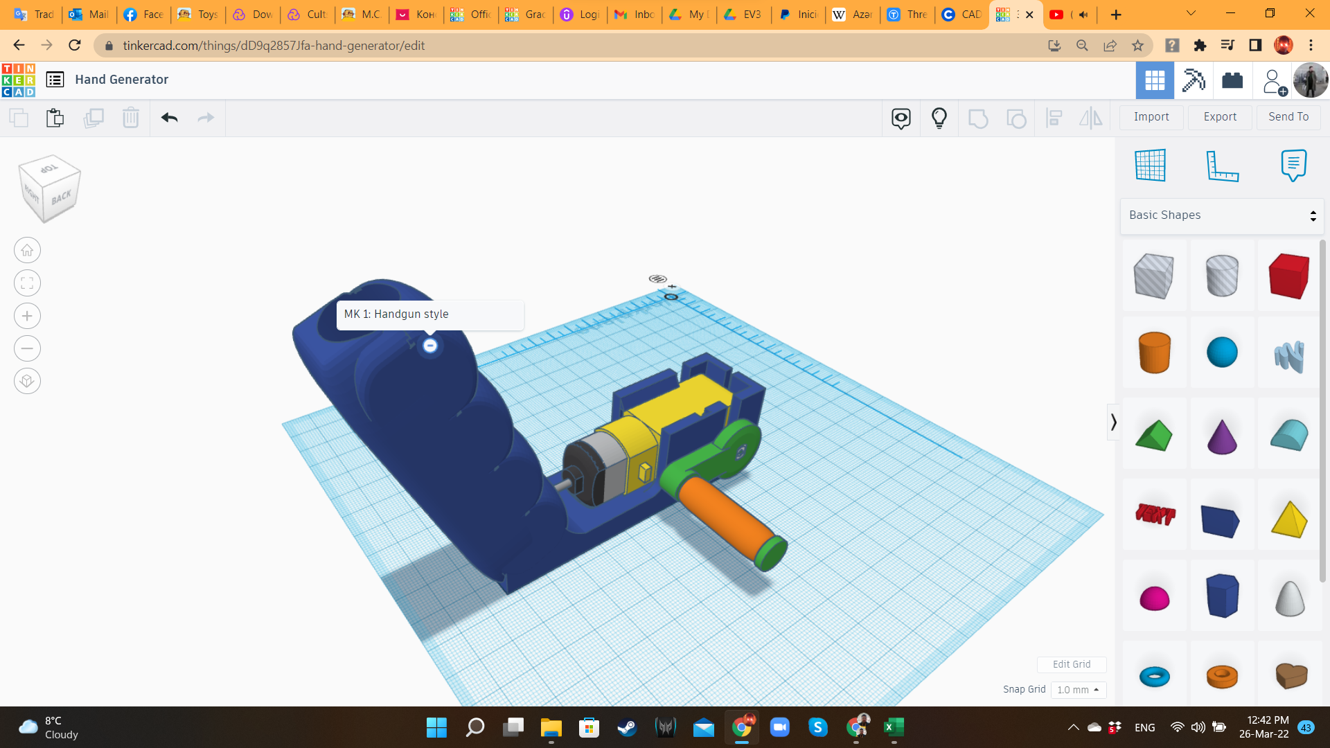
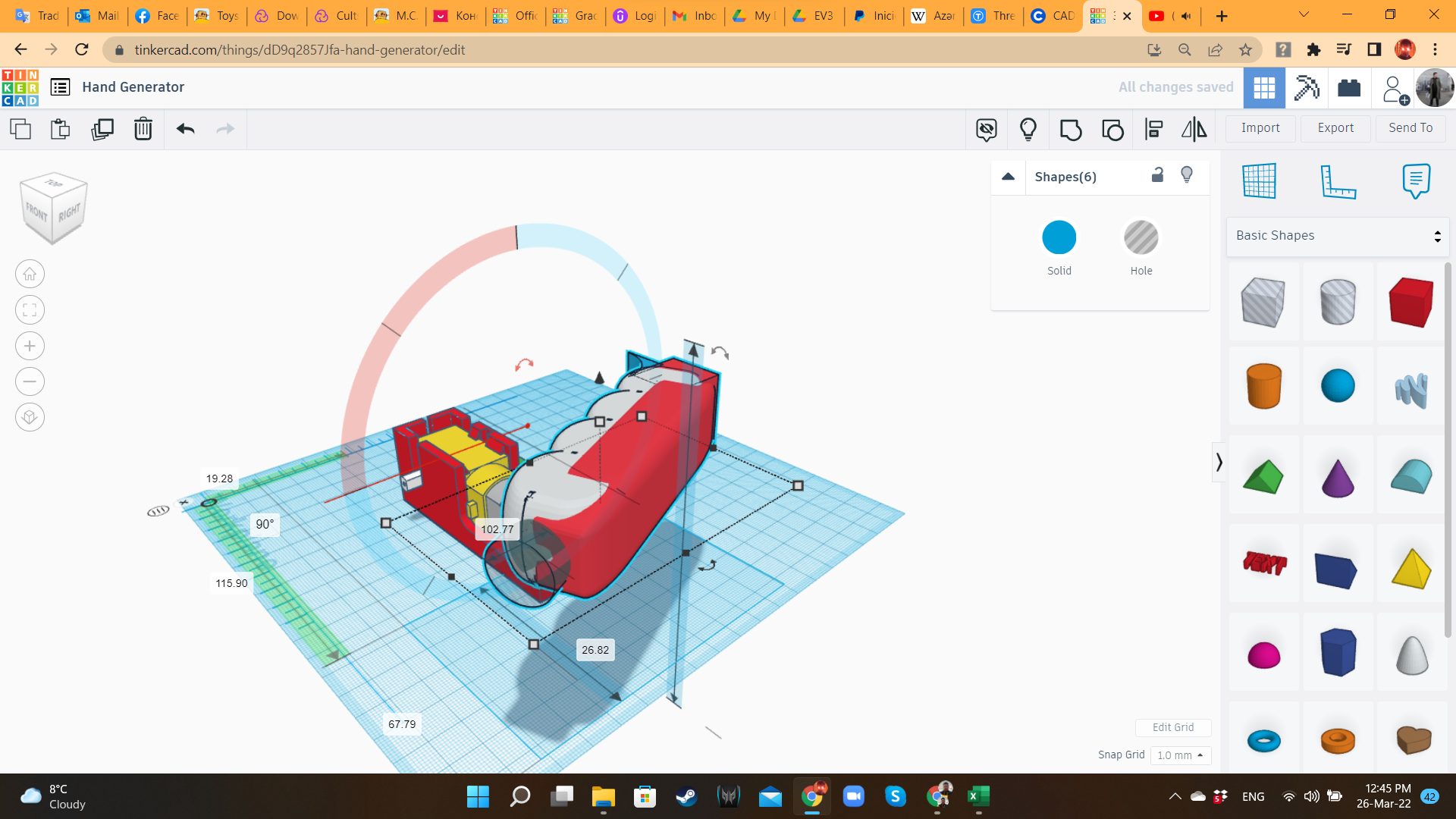
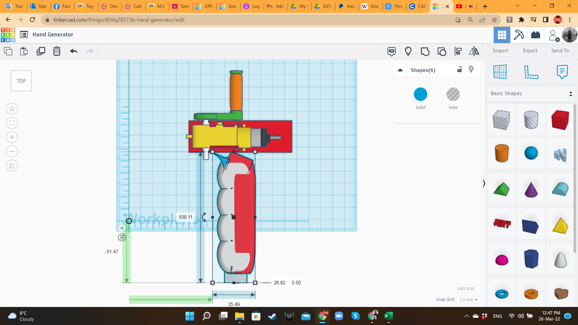
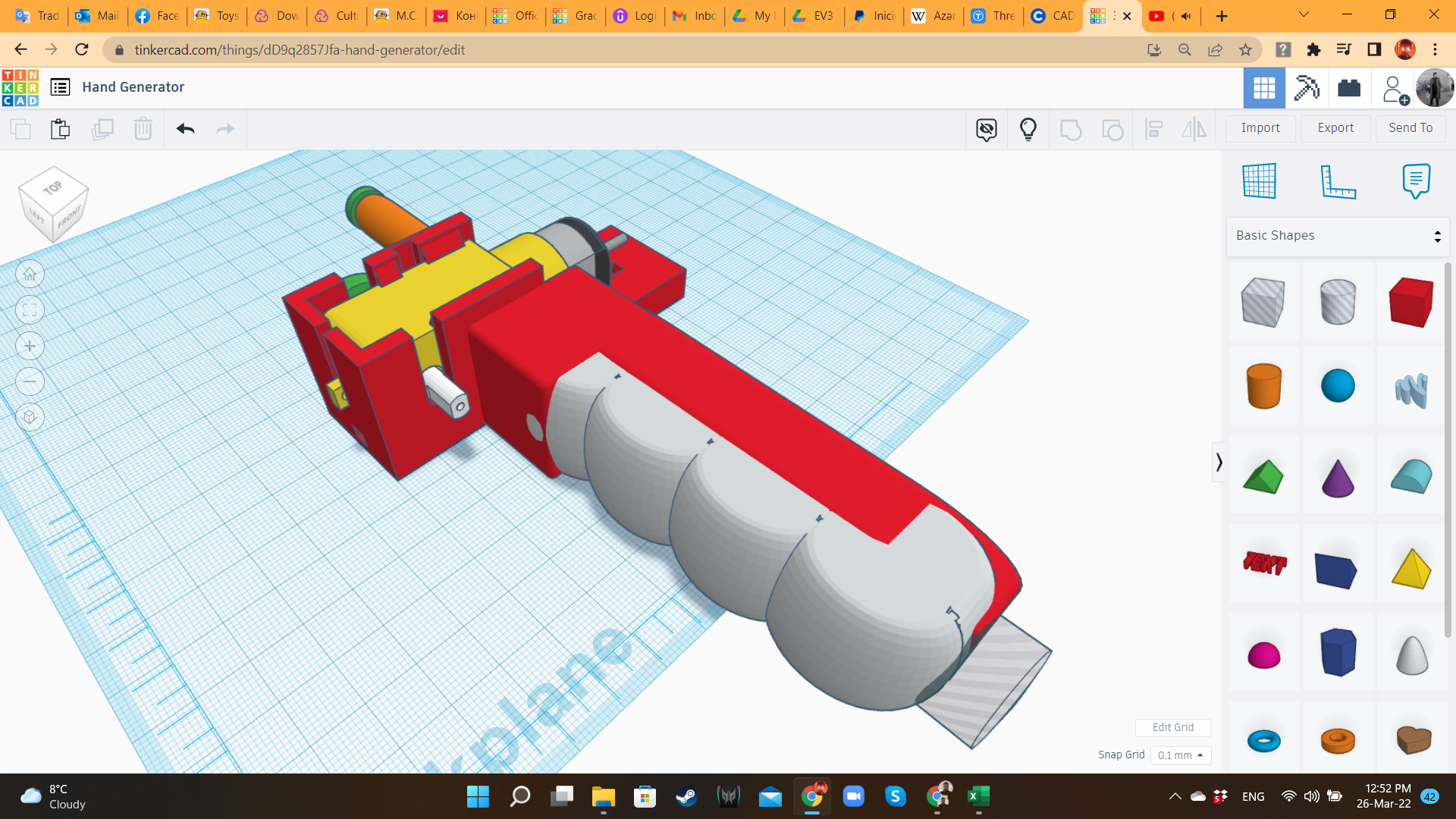
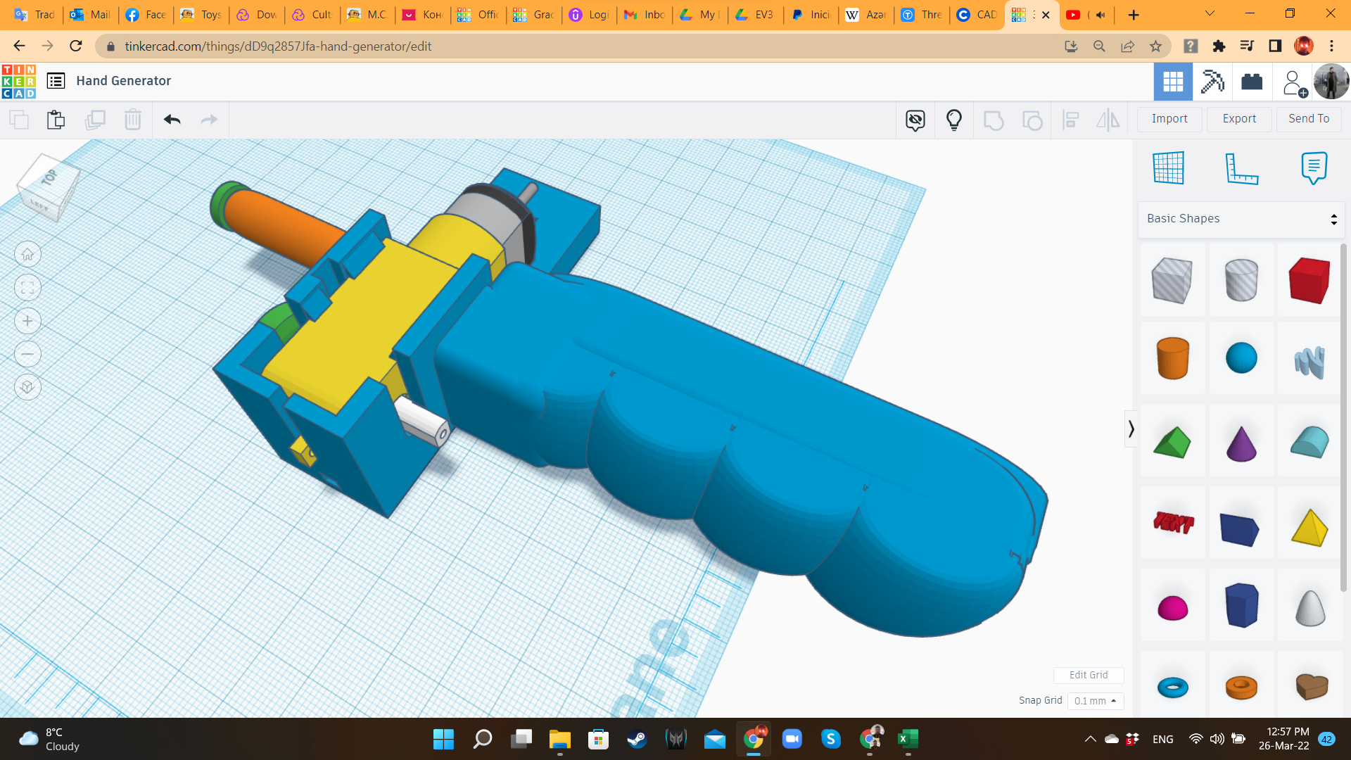
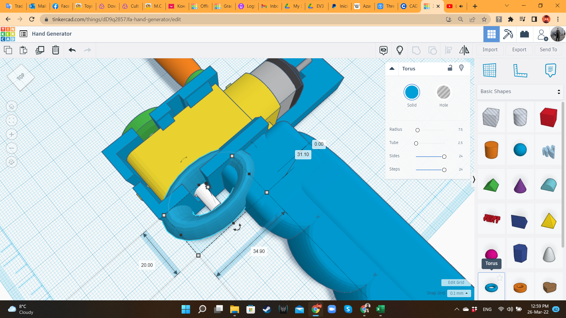
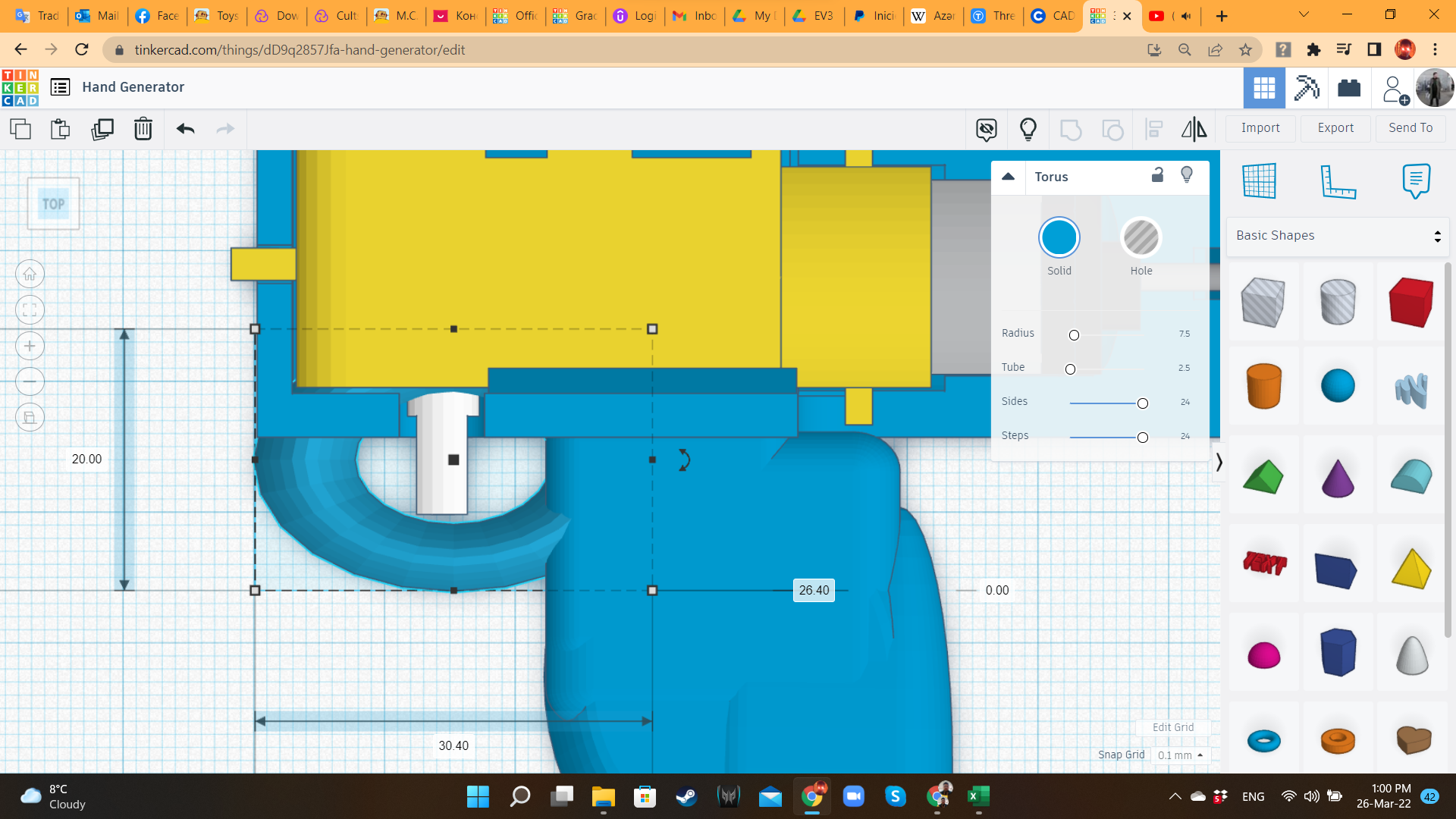
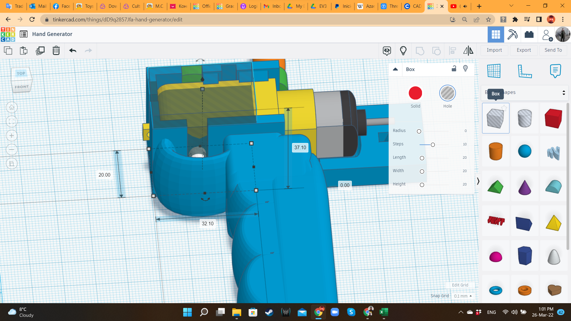
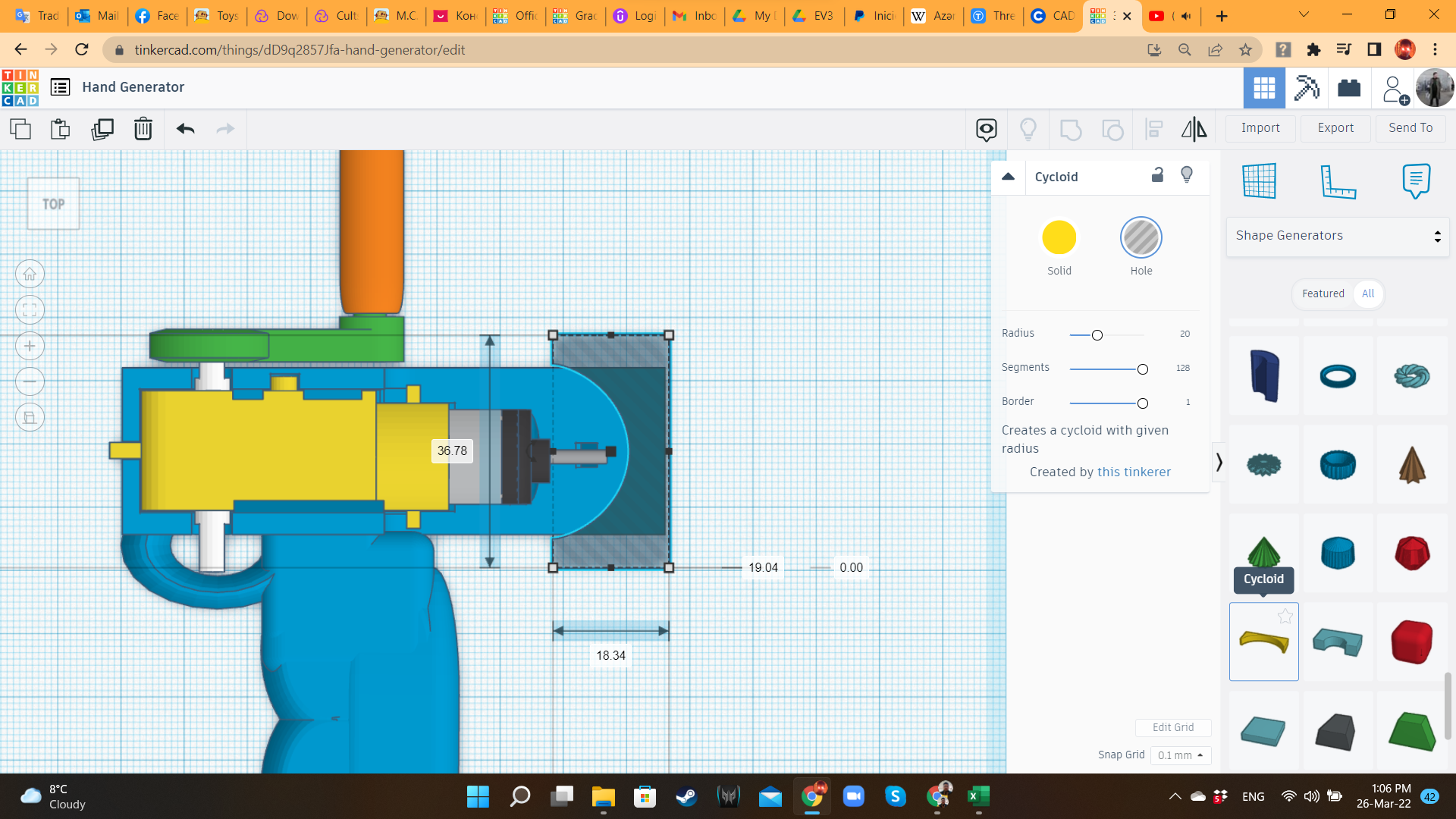
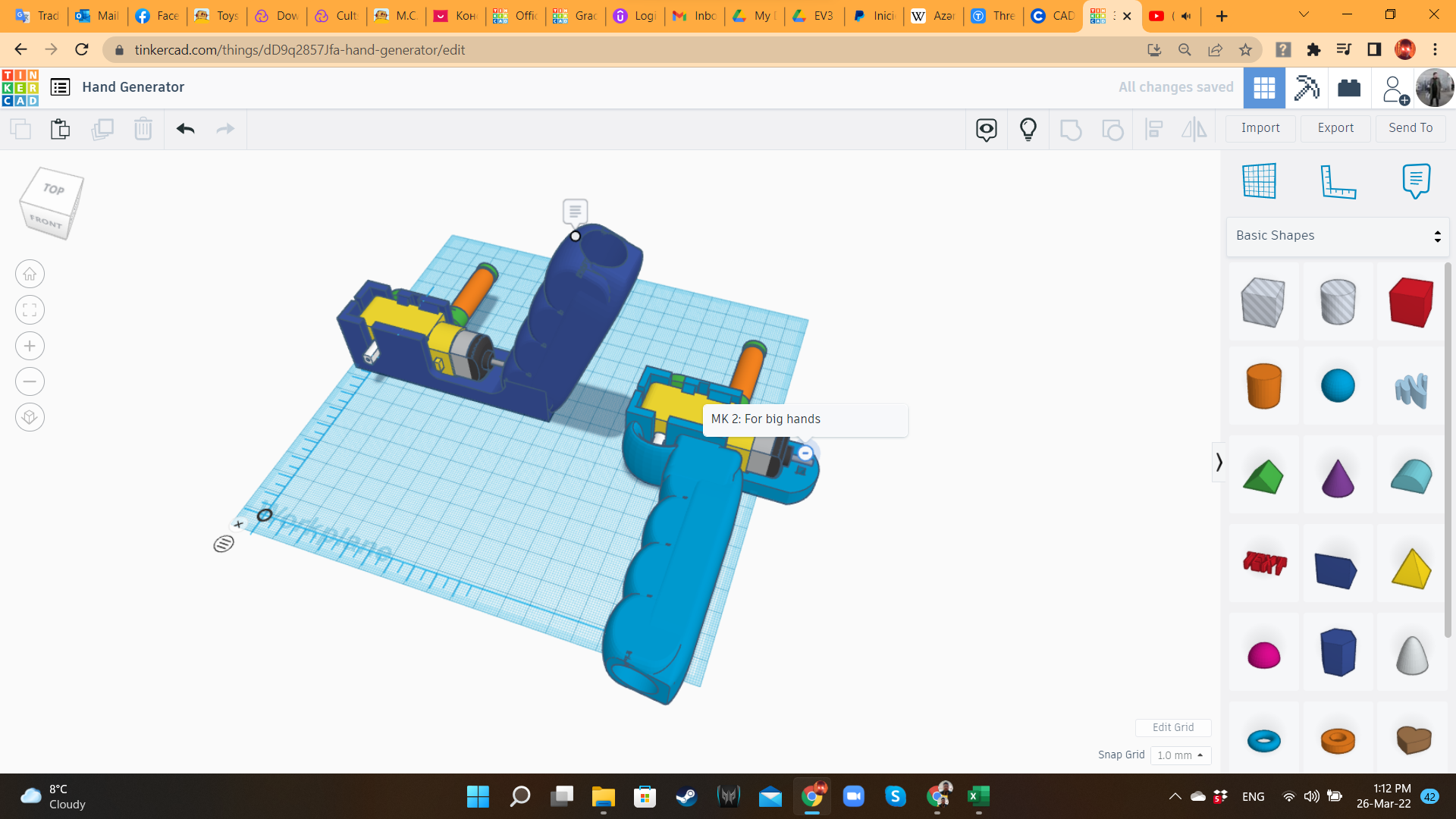
After grabbing a whiteboard marker and pretend that I was spinning the crank, I realized that there was no way of turning it without hitting my hands. I was a very uncomfortable position! So, I created a duplicate of the Hand Dynamo, ungrouped the shapes, and moved the handle to the opposite side of the crank. It looked very practical! So i decided to go with this improved version.
Hand Dynamo 5: Slicing and Printing
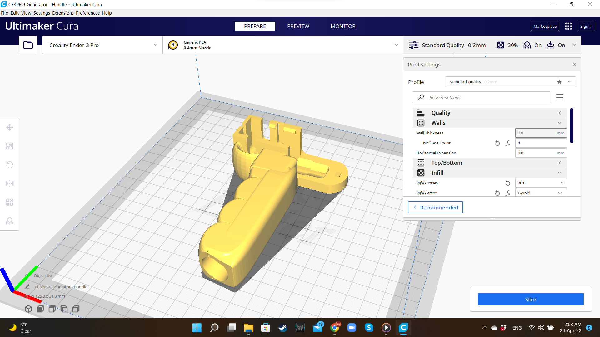
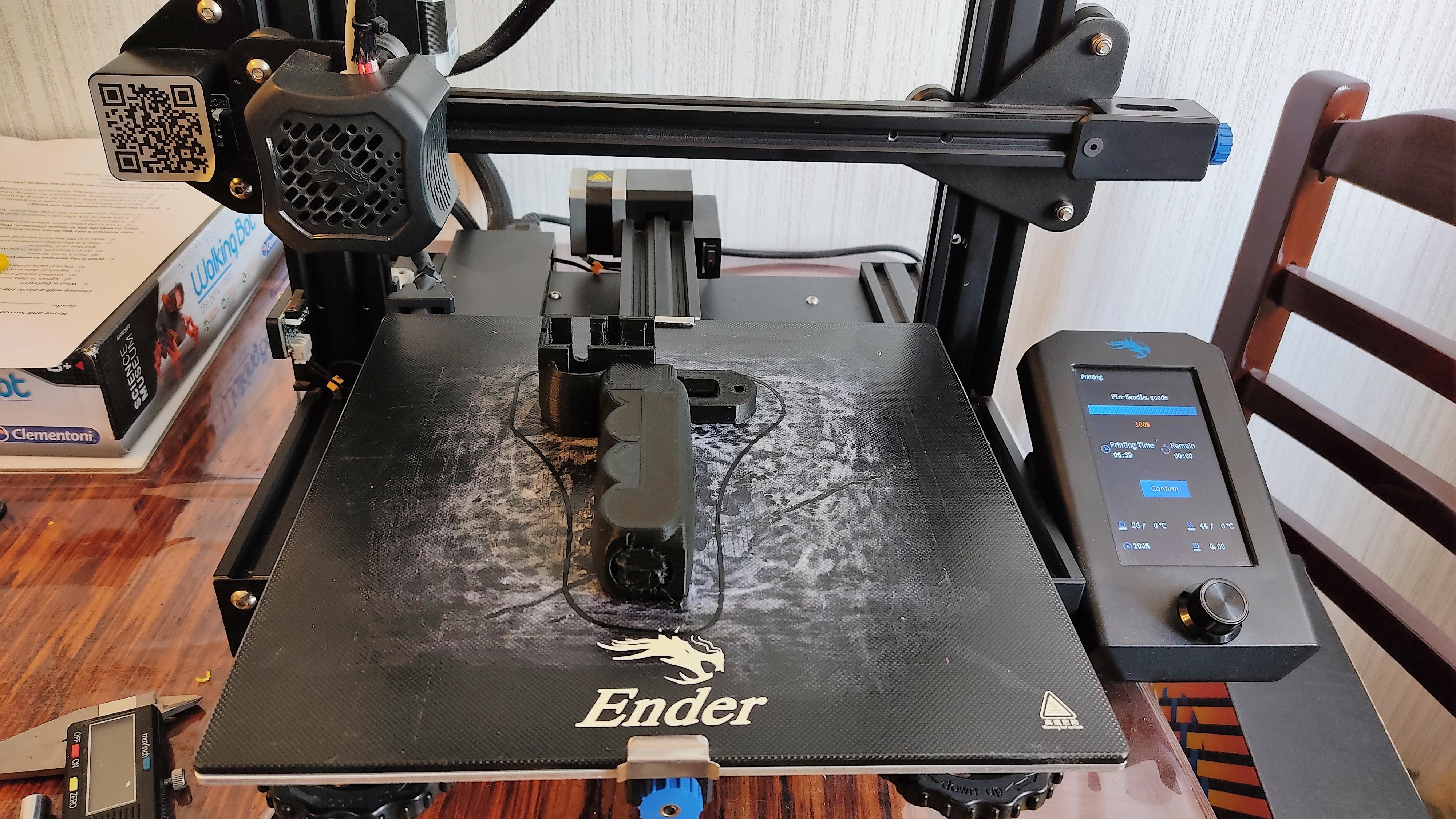
I exported the STL files of the two components (Handle and Crank), and opened them in the slicer.
I used the following parameters:
- Printer: Creality Ender 3 V2
- Slicer: Ultimaker Cura 4.8.0
- Material: PLA (But I recommend to use a mechanically stronger material, like ABS or PETG)
- Printing Temperature: 200°C
- Infill: 30% (handle), 100% (crank)
- Supports: Linear
- Raft: yes (I love Raft).
- Scale: 100%
Hand Dynamo 6: Assembling the Handle
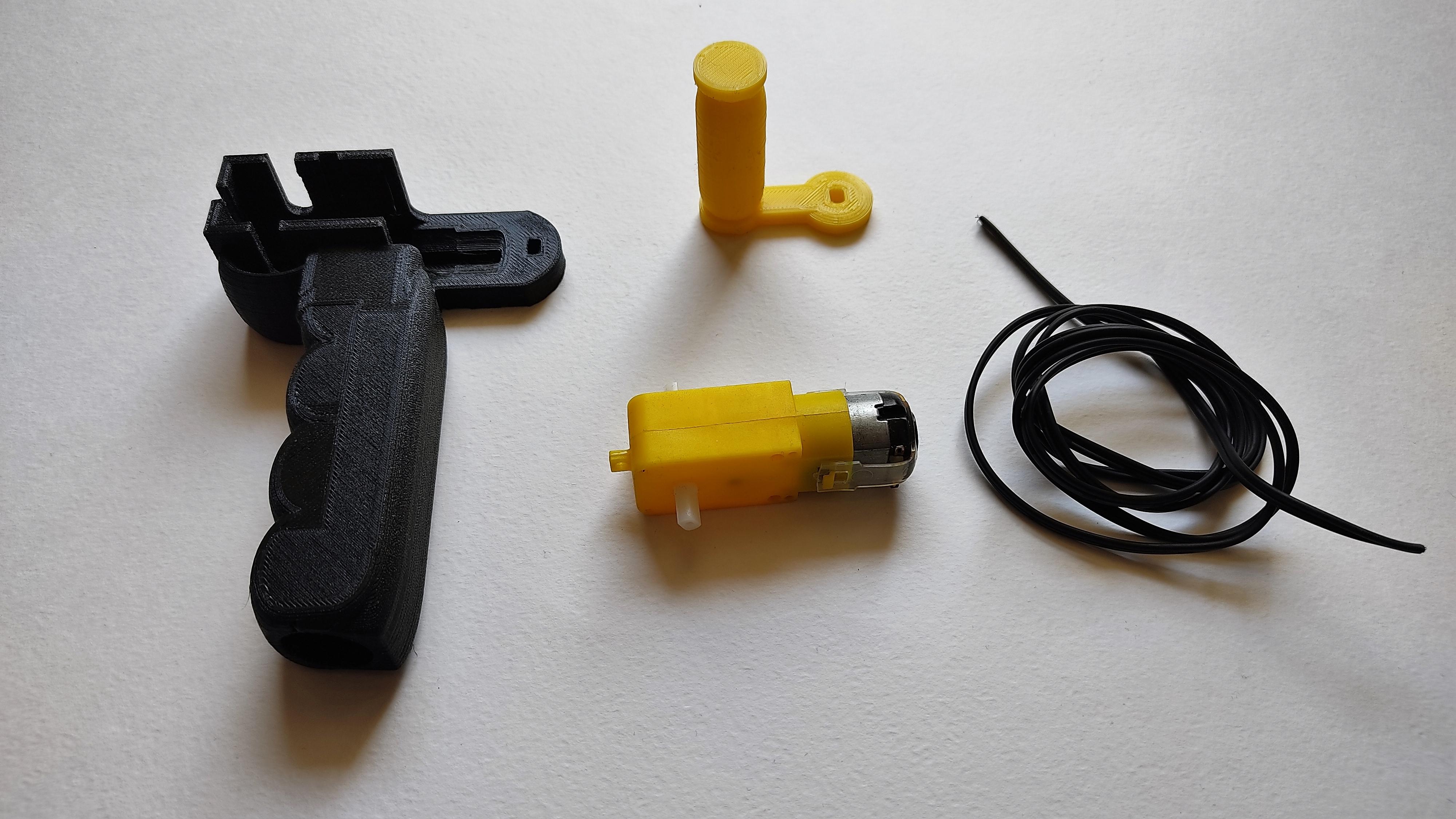
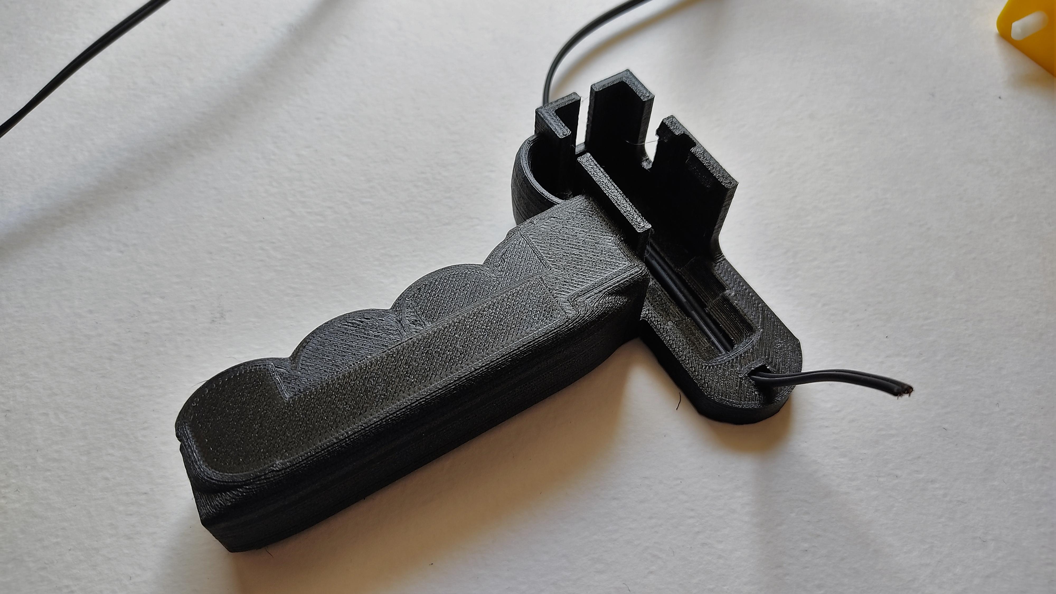
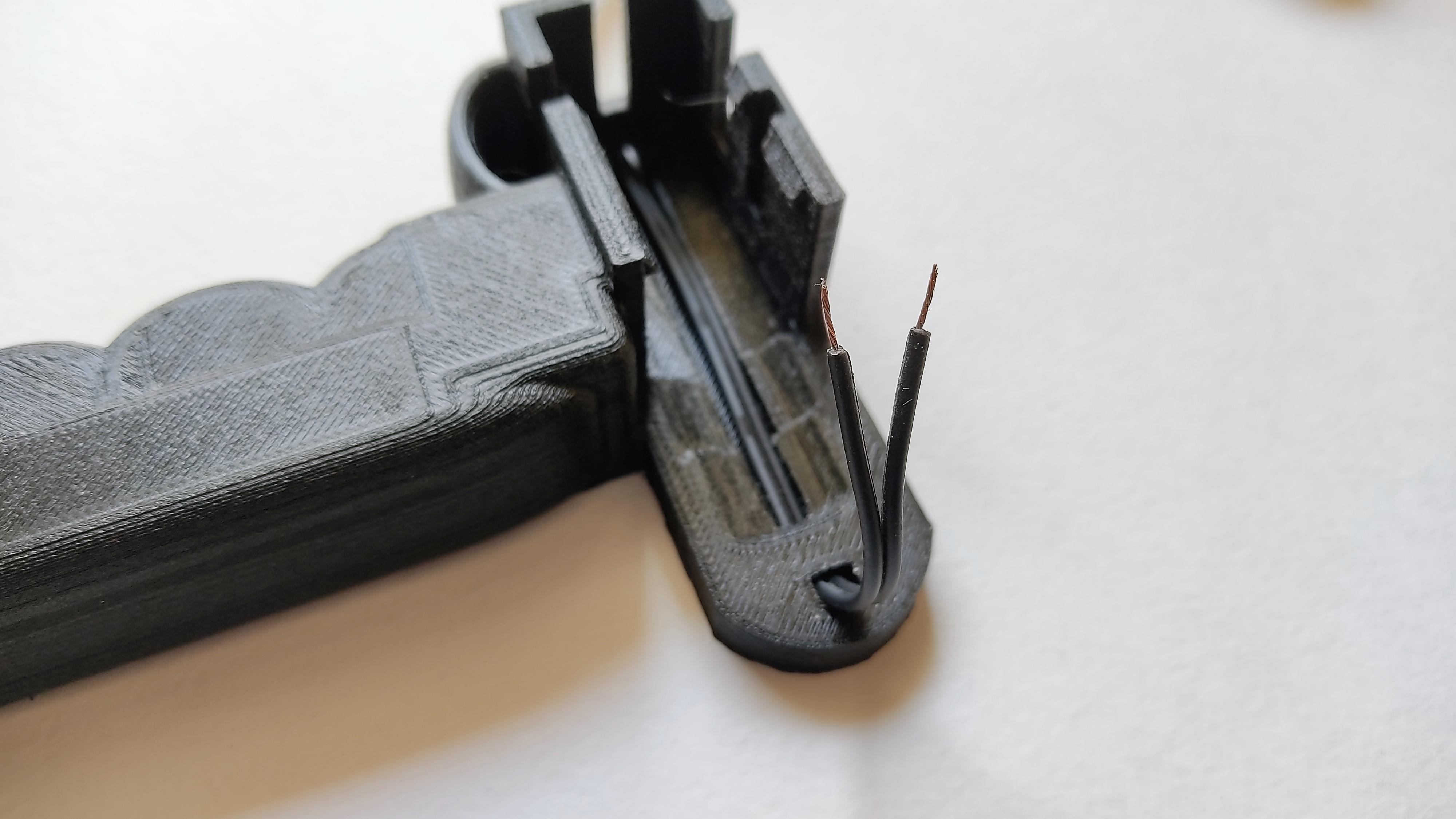
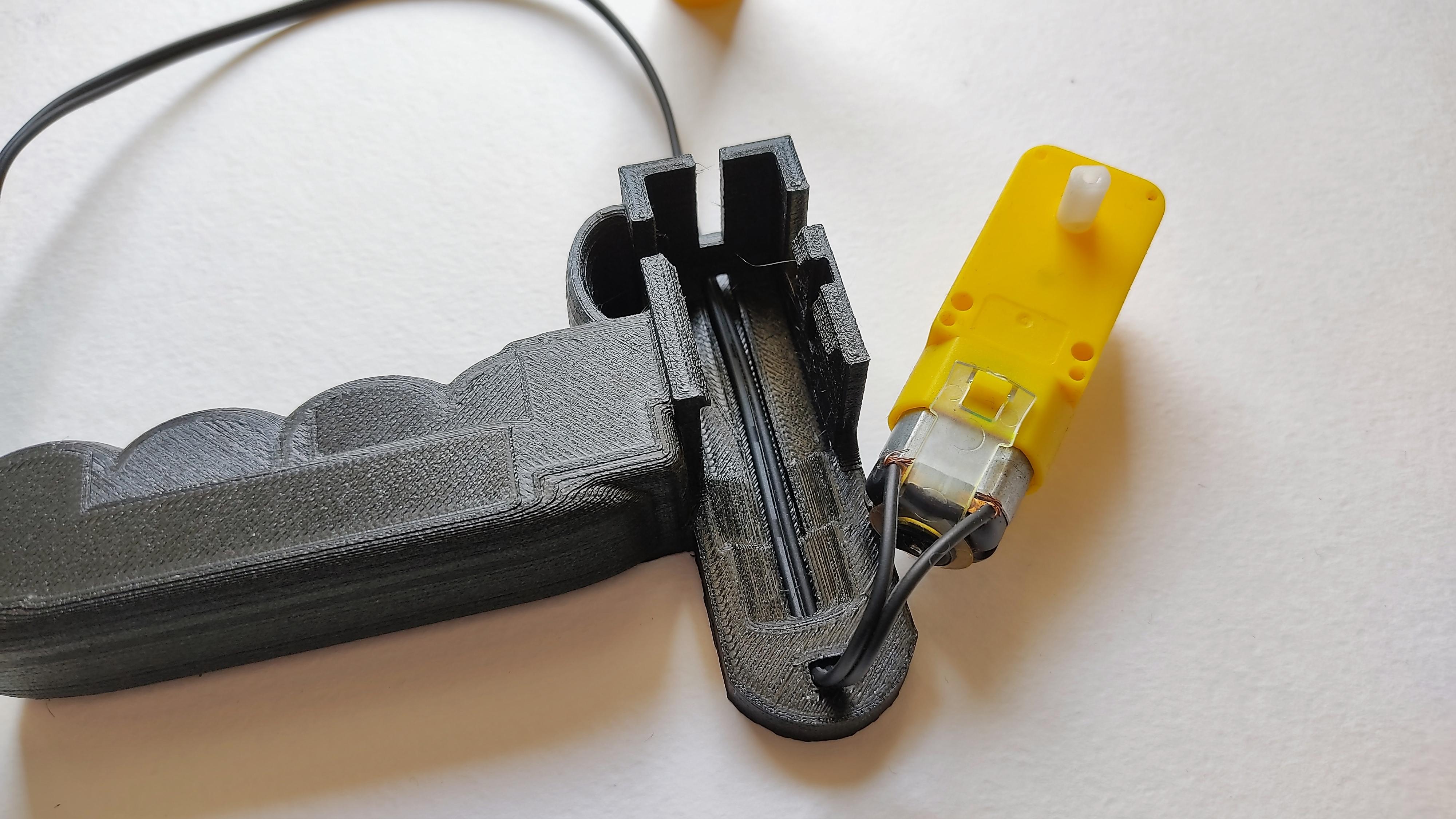
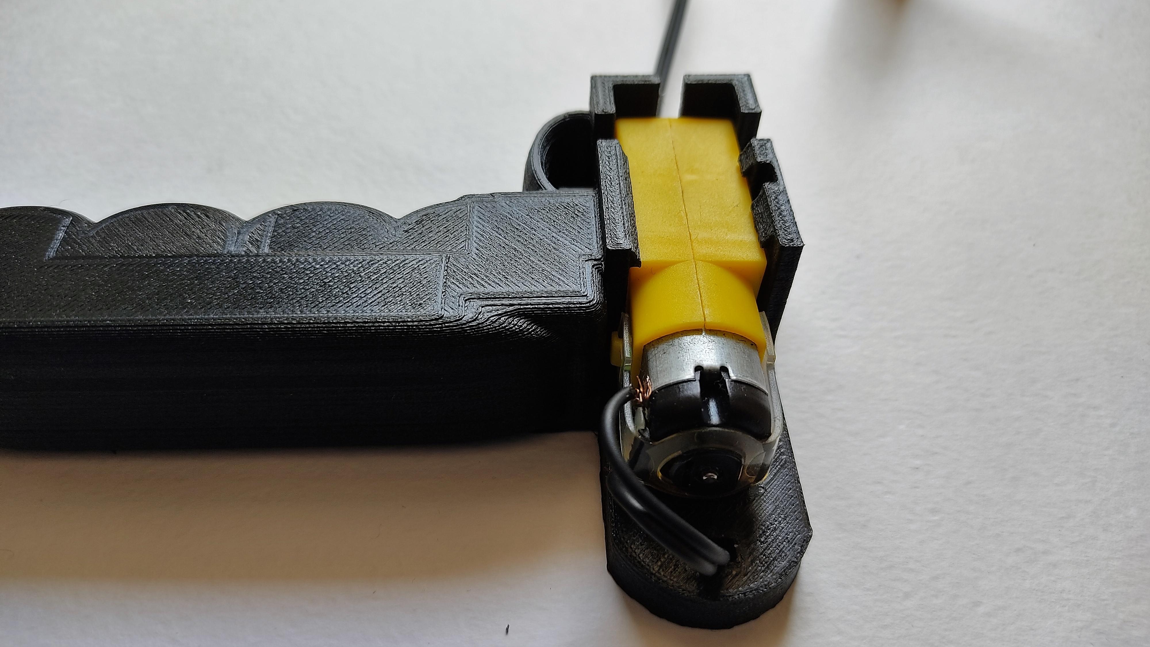
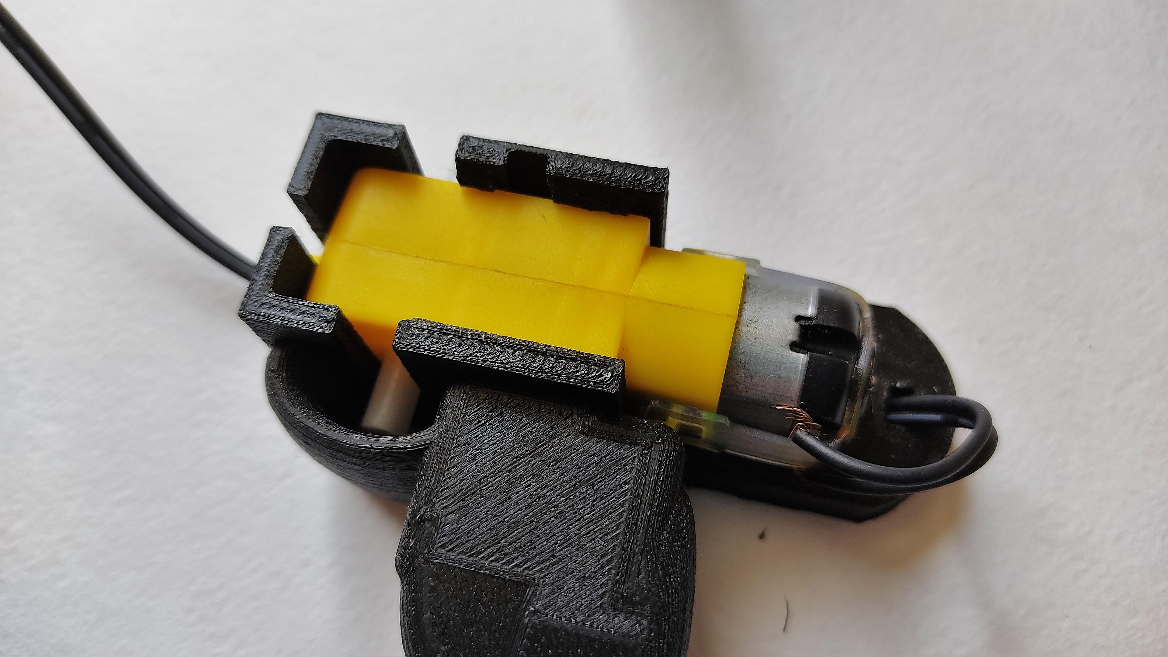
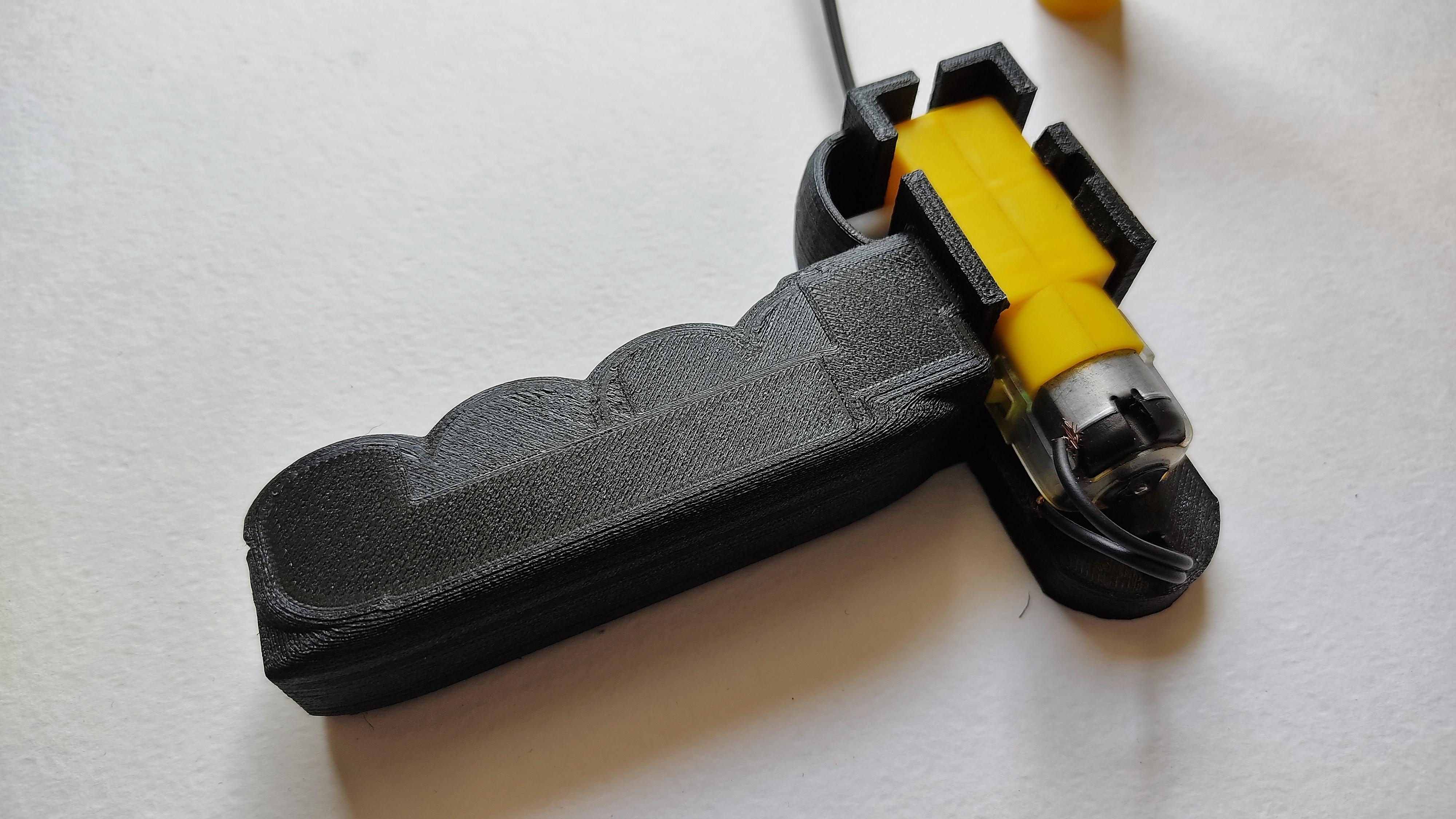
Remove the supports from the 3D printed parts. Then, insert the cable trough the tunnel. Then, remove the rubber cover from the end. Connect each wire to each motor pin. Then, being very carefully of not breaking the tabs, insert the gearbox in the respective position.
Hand Dynamo 7: Assembling the Crank
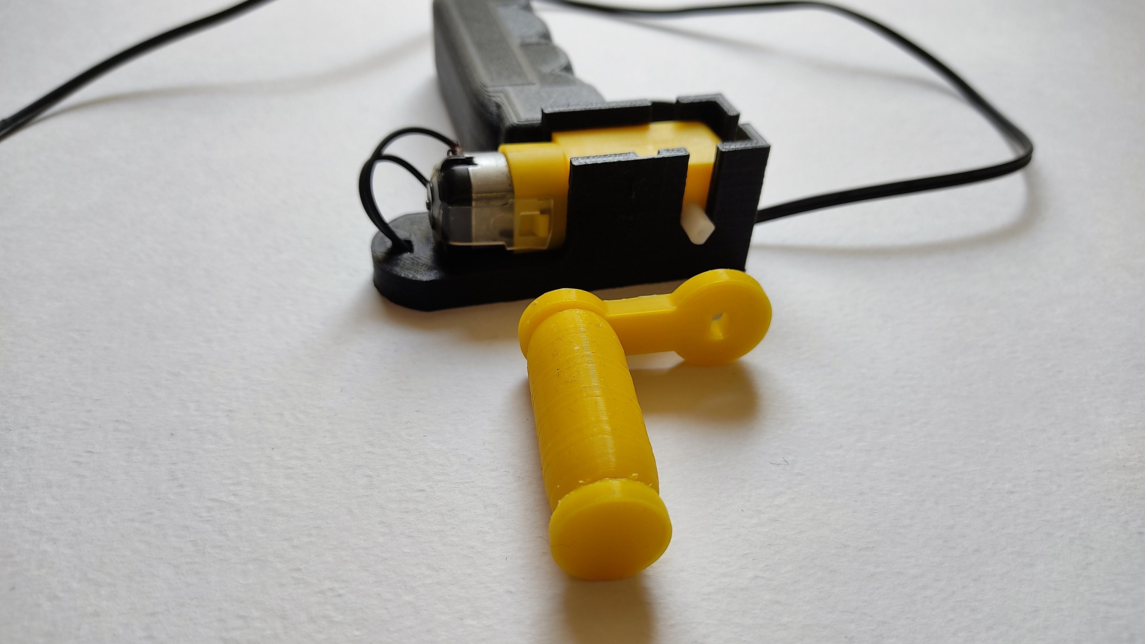
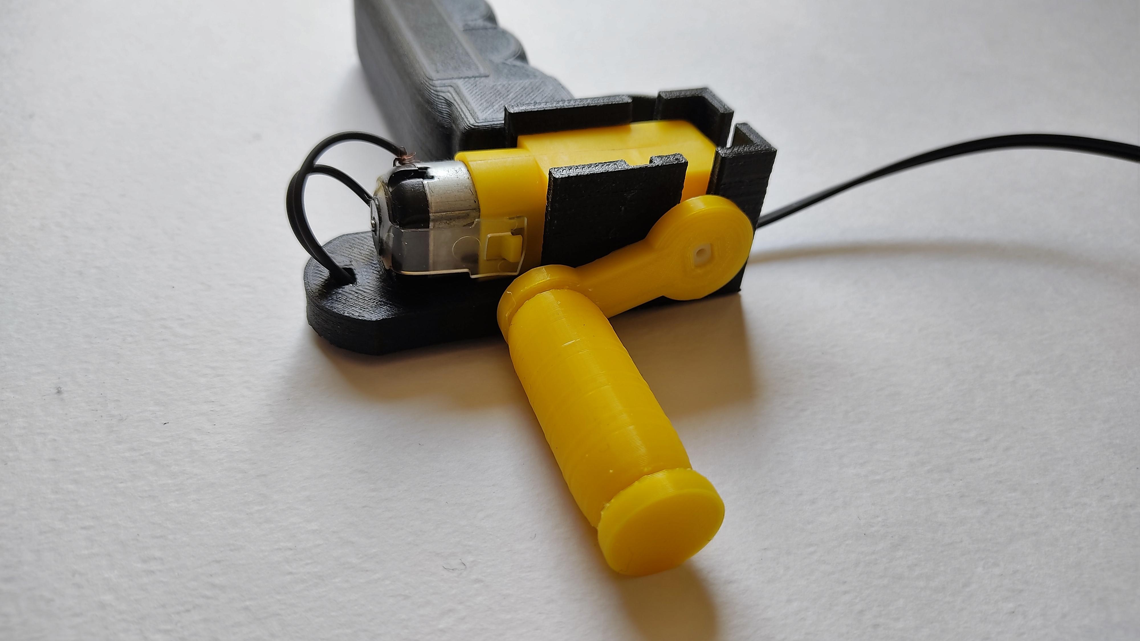
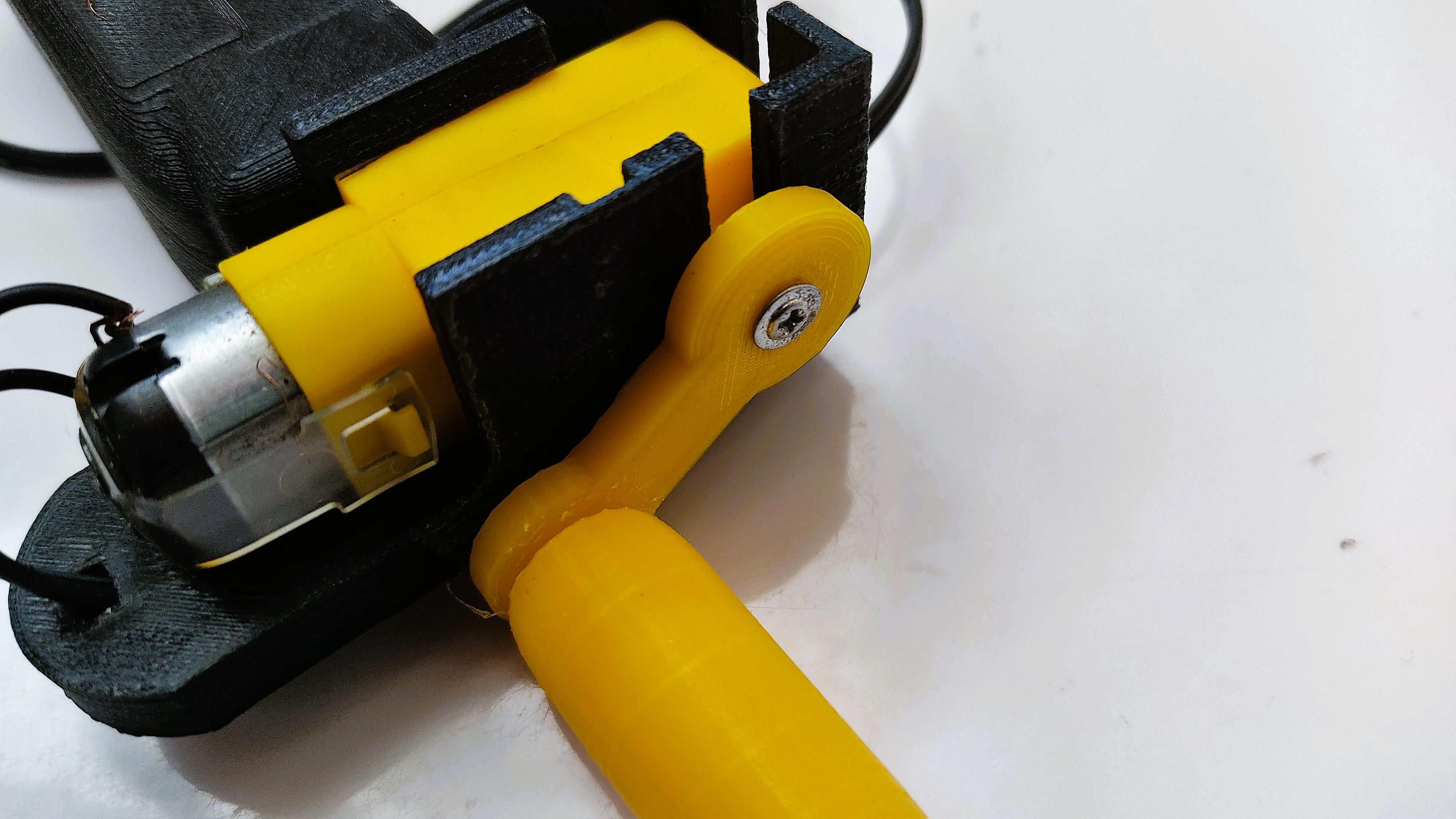
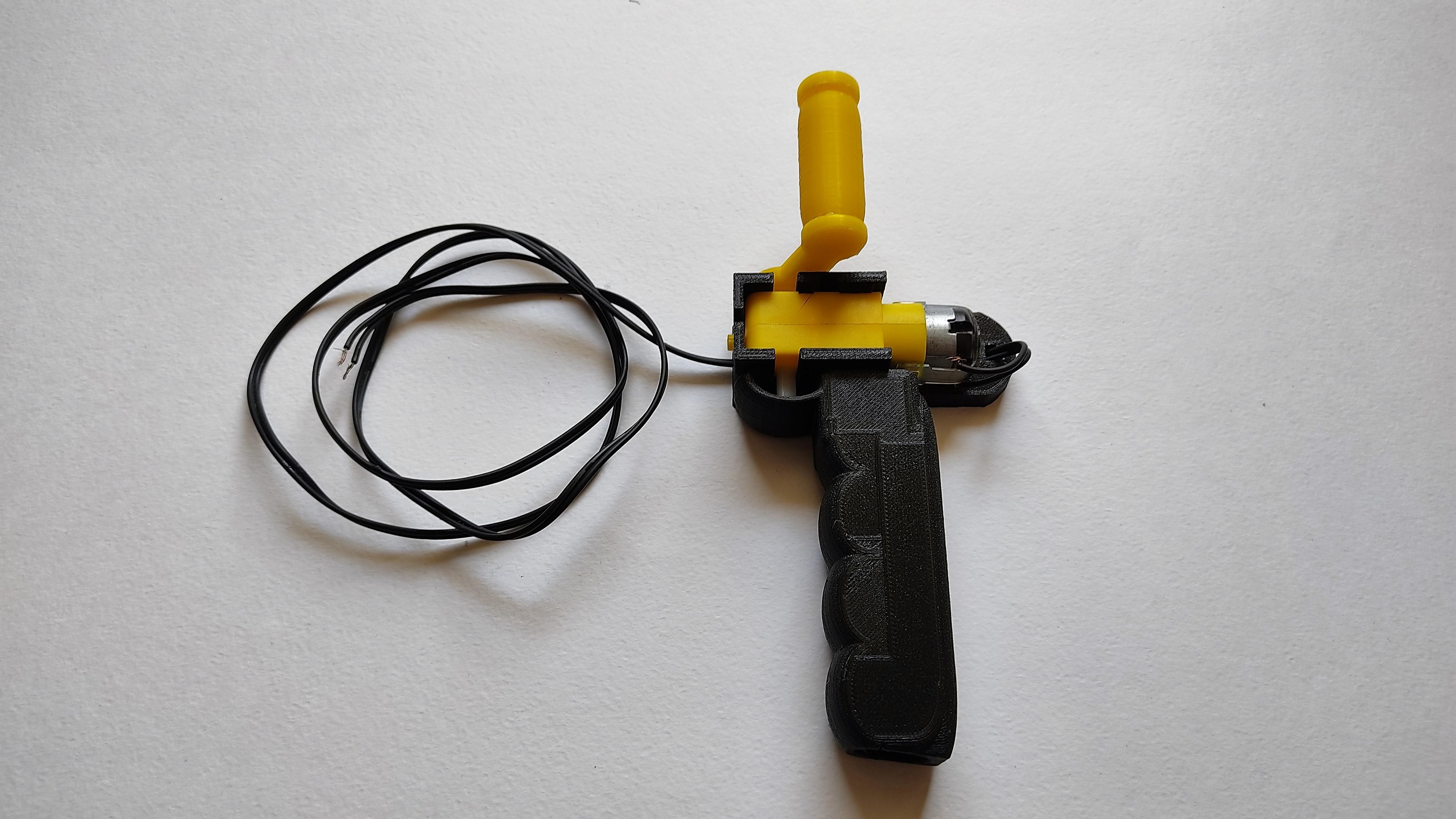
Insert the gearbox axle into the crank's hole. Then, fix the crank to the axle, using a screw. The crank is ready for testing.
Hand Dynamo 8: Test With a Walking Robot
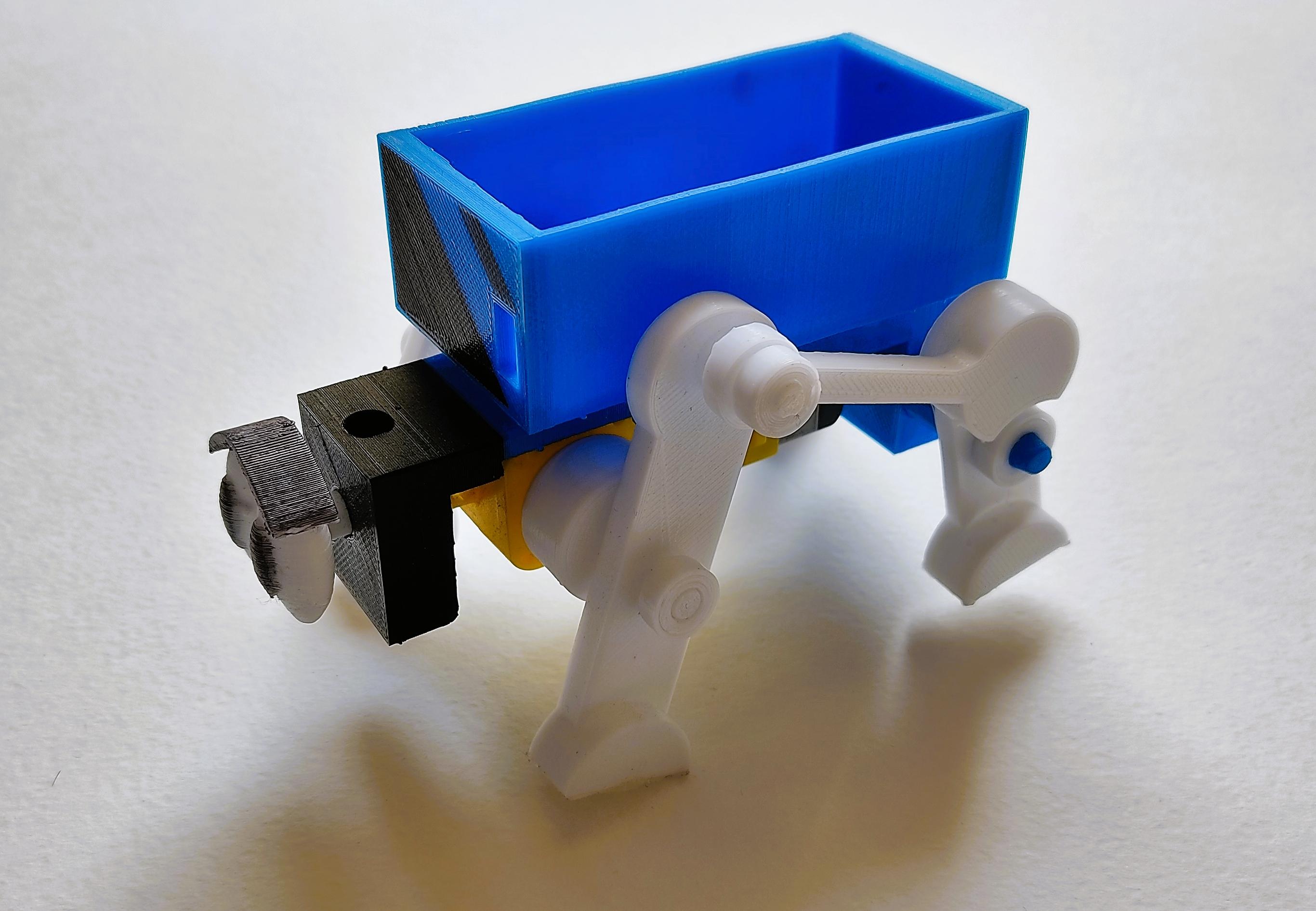
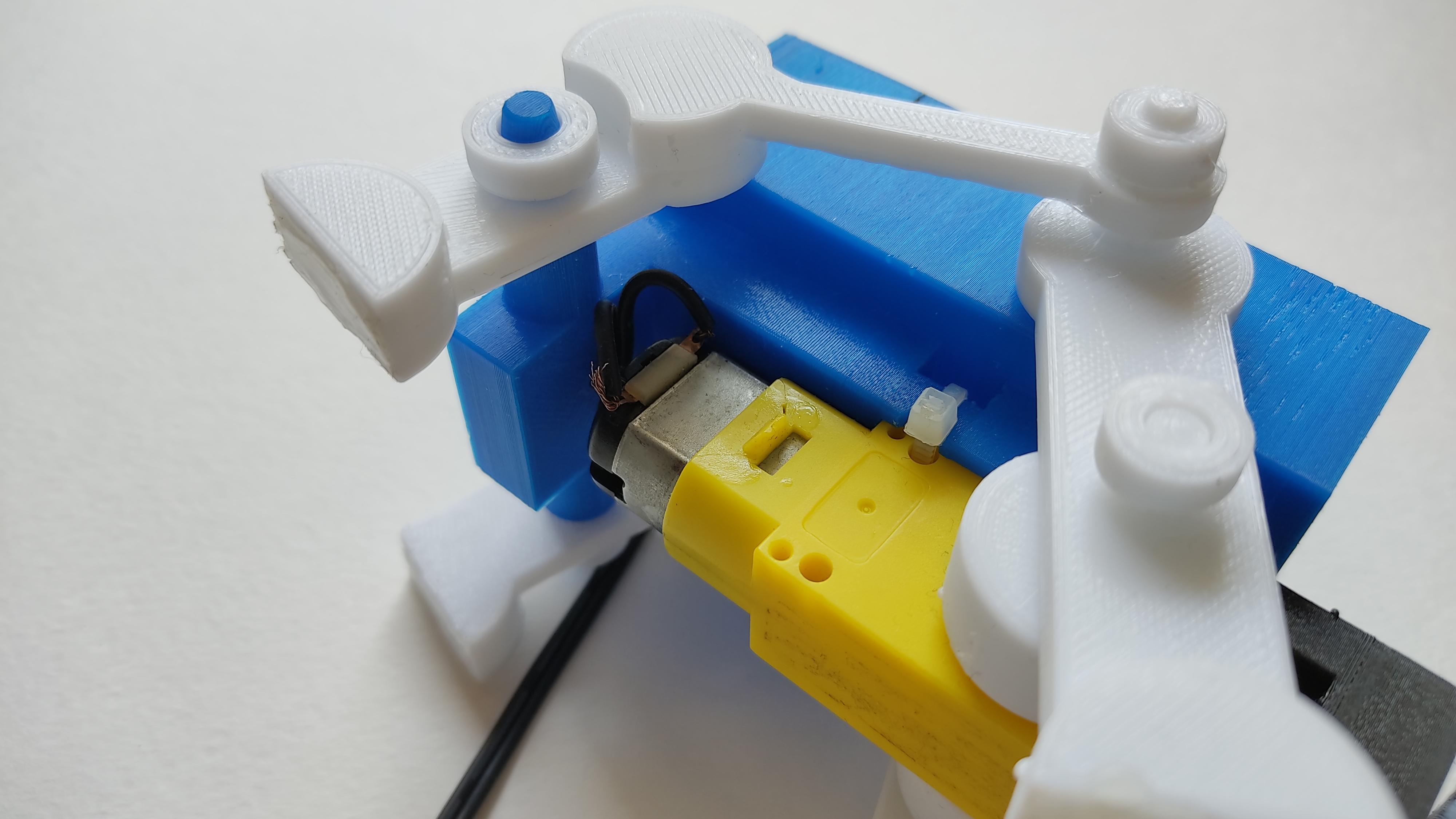
To test if it was really working, I brought one of my simple walking robots (you can find the link to that instructable here, or you can build one using the shapes from the "Vehicles and machines/robots" library). I connected the wires from the Dynamo to the pins of the robot's motor and... it didn't work. After almost giving up because I considered that the Laws of Physics were playing a joke on me, I realized that the gearbox was broken. I replaced it for a new one, and it worked like a charm!
Ok, the Hand Dynamo was effective to move a small and light robot, but very slowly. Would it be able to move something heavier, and faster?
The answer would be revealed soon.
Hand Dynamo 9: Failures and Improvements
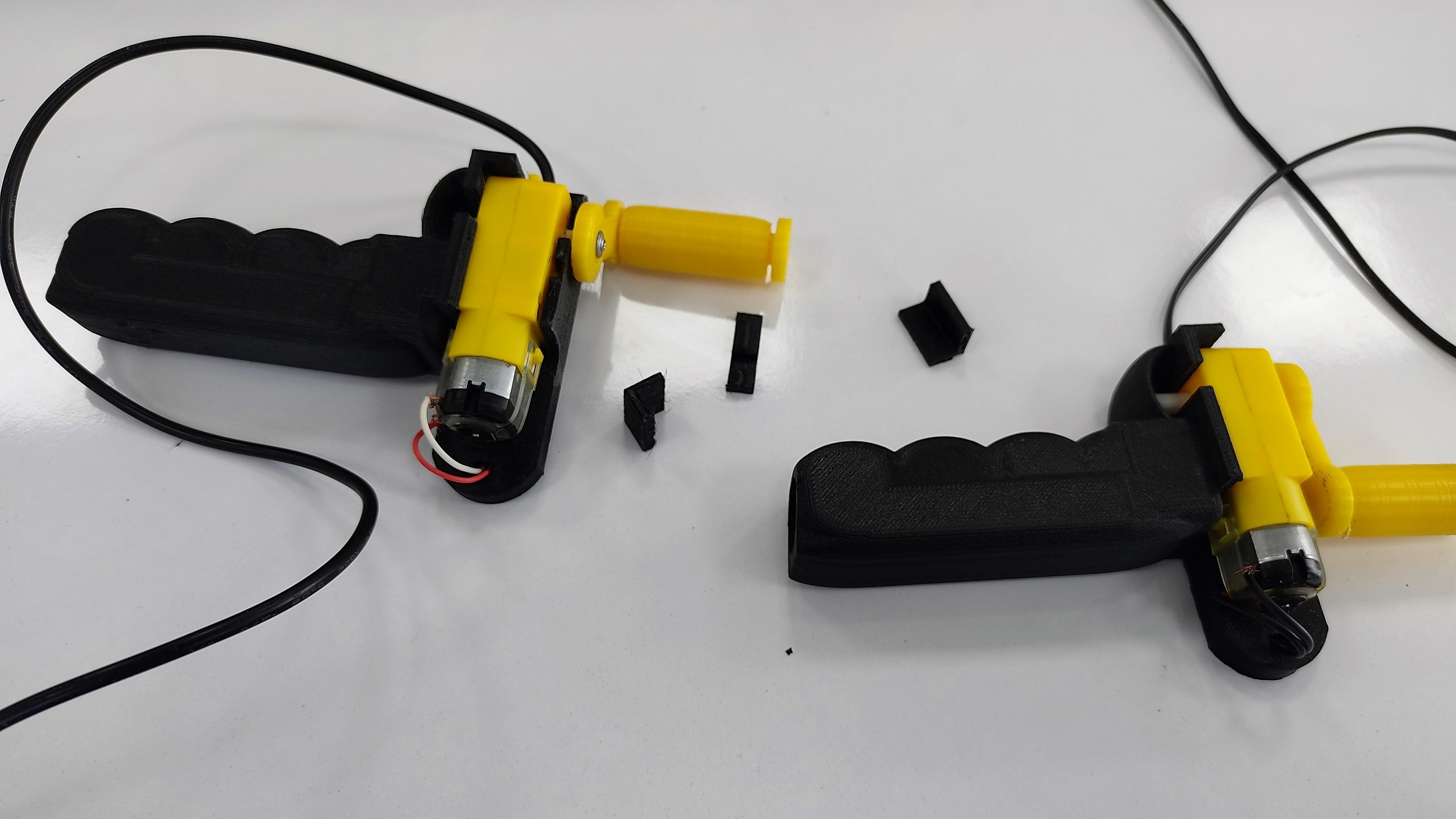
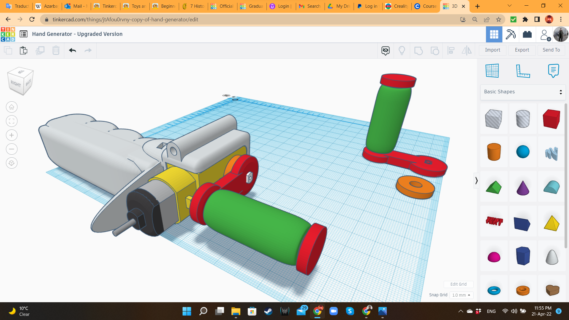
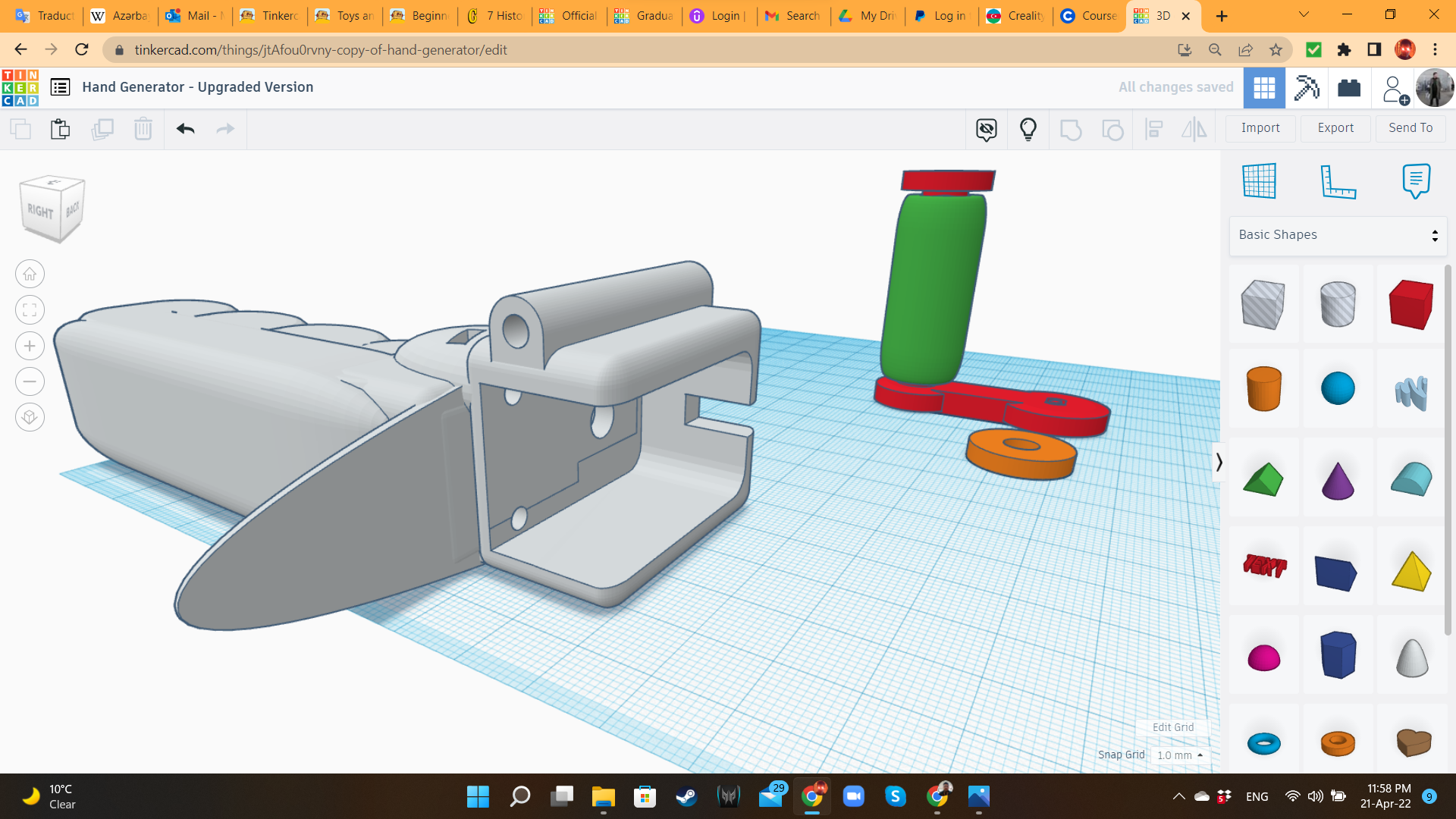
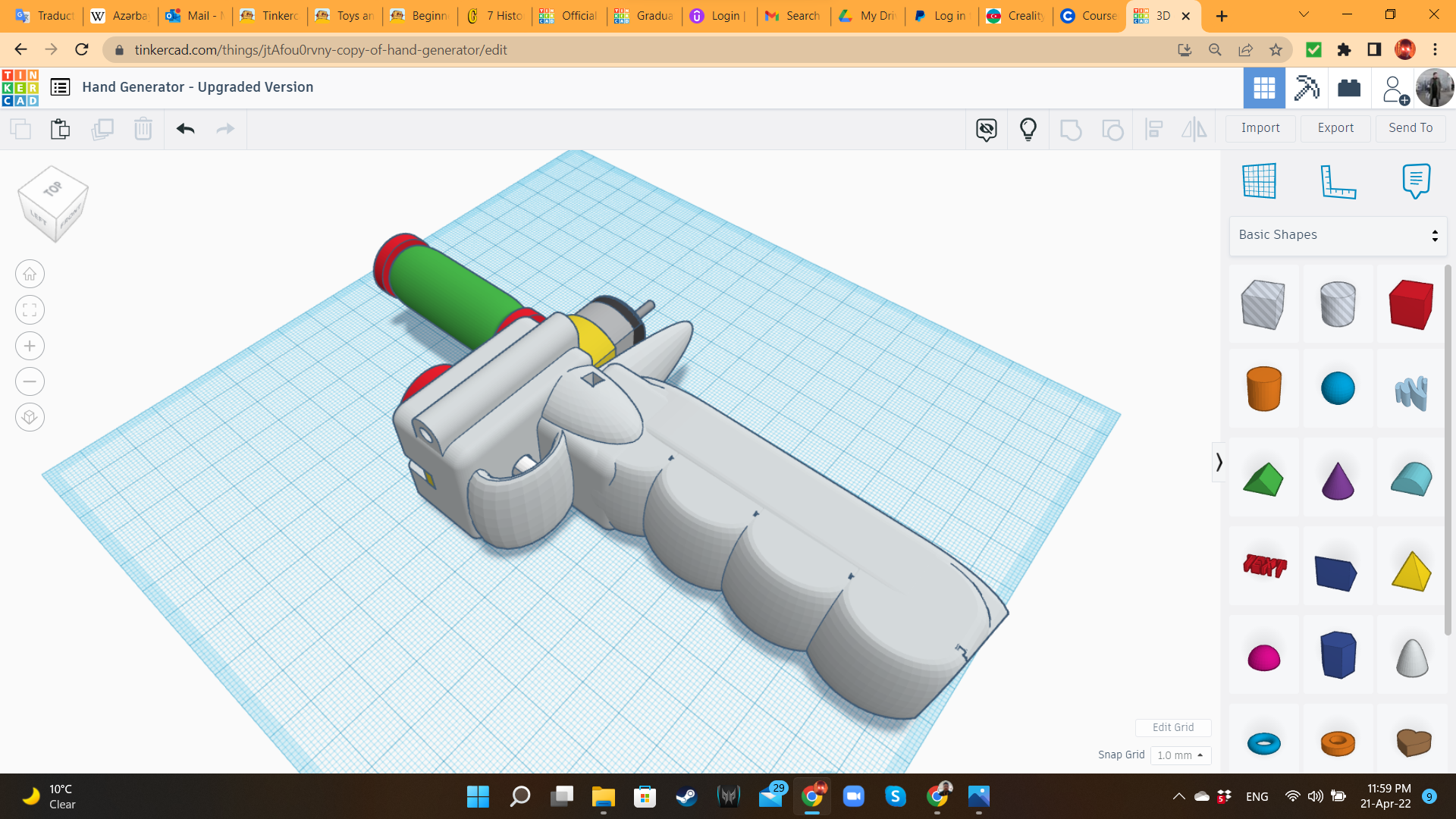
After my own experience assembling the Hand Dynamo, and testing it with the real users (two adults and several kids), I found the following issues:
- The cable was very hard to insert through the respective hole.
- Due to the famous property of PLA material, of breaking before bending, it was difficult to insert the gearbox without breaking the tabs, or causing excessive stress to them.
- Also, the tabs were no match for the stress of competitive crank spinning. So after 3 uses, fragments of the handle started falling down.
For that reason, I modified the design, changing the tabs for full walls, changing the way the gearbox fits into the handle, creating some holes so the gearbox could be attached using a zip-ti, and adding a small washer to reduce stress over the gearbox's axle.
Then I printed this upgraded design, using PLA, 30% of infill, a 4-walls shell, and gyroid pattern.
Hand Dynamo 10 (Upgraded): Assembling the New Kit
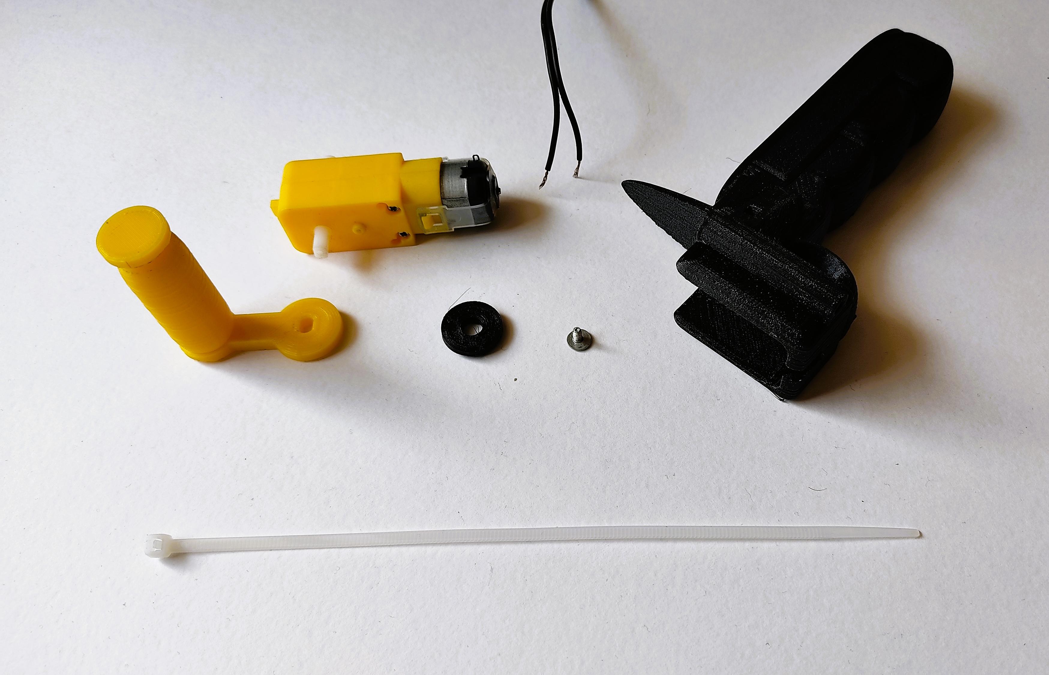
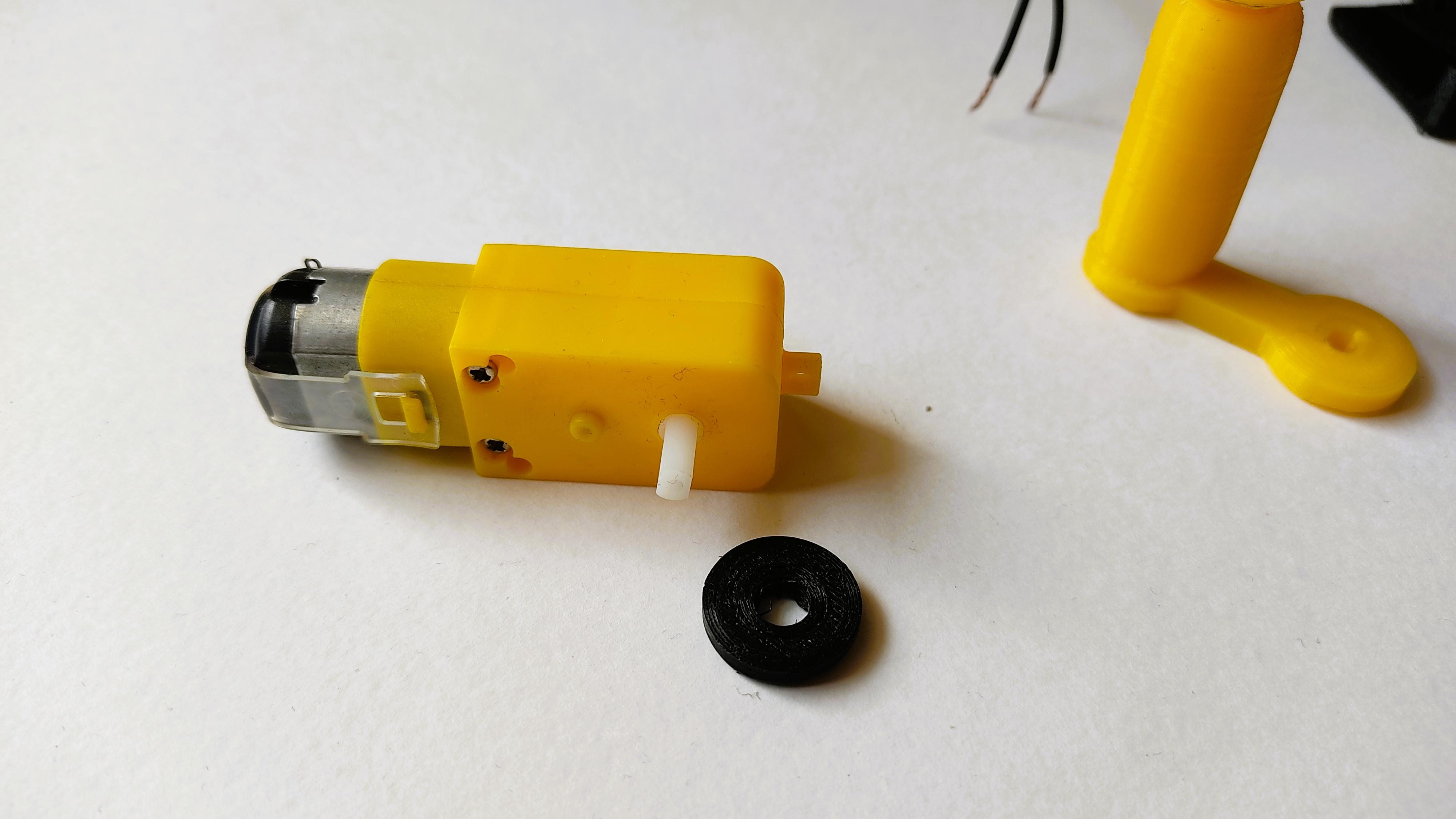
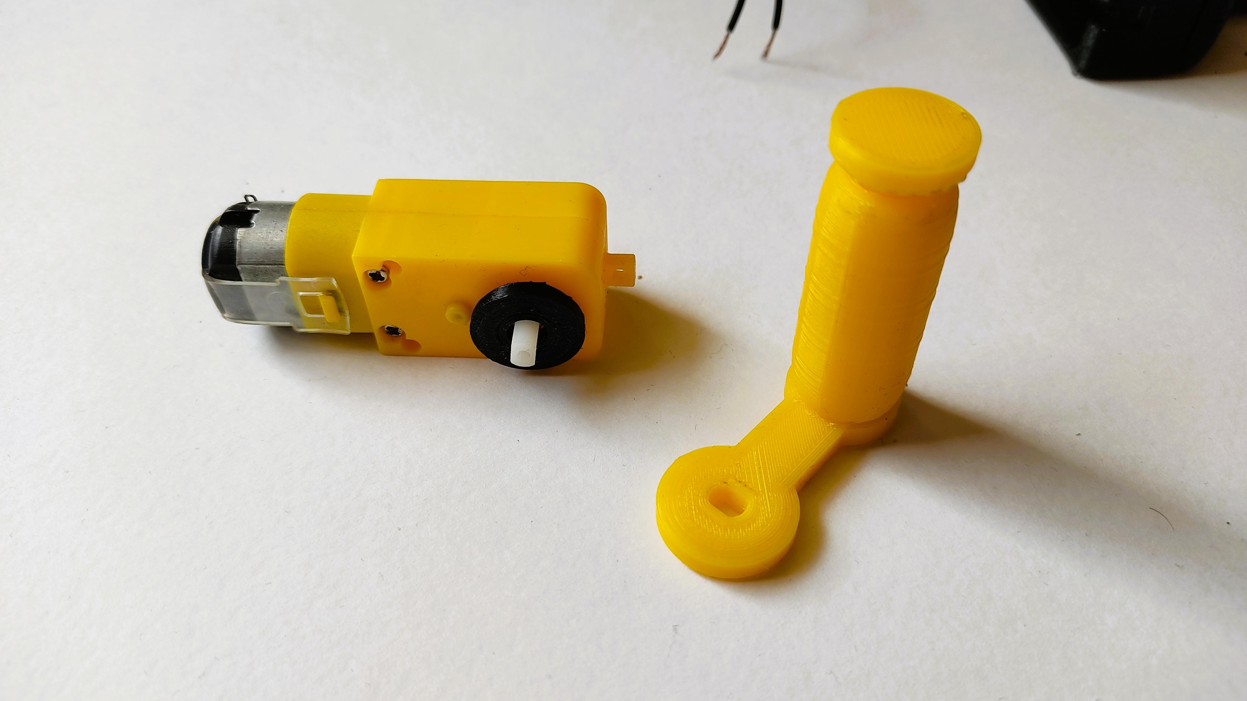
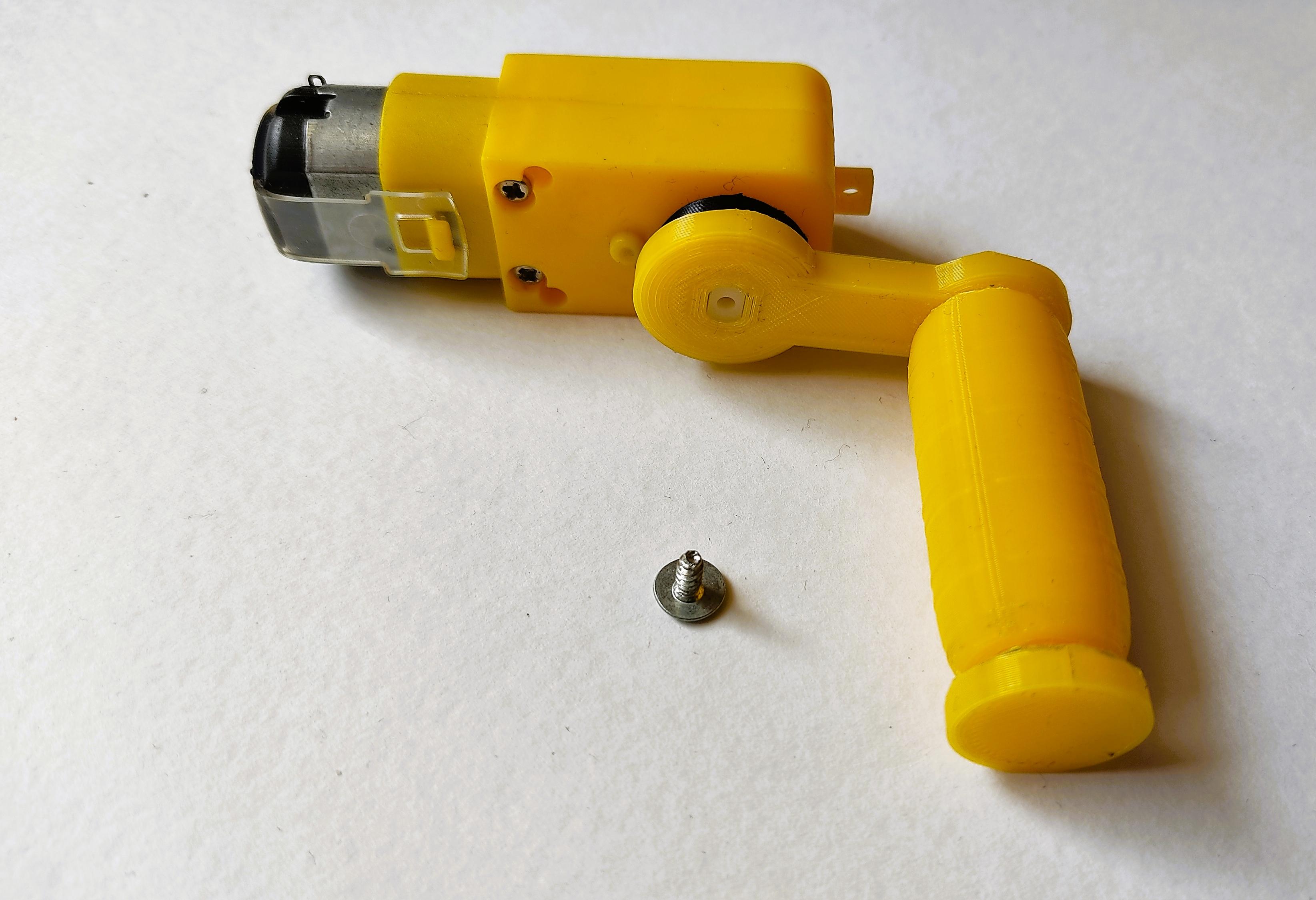
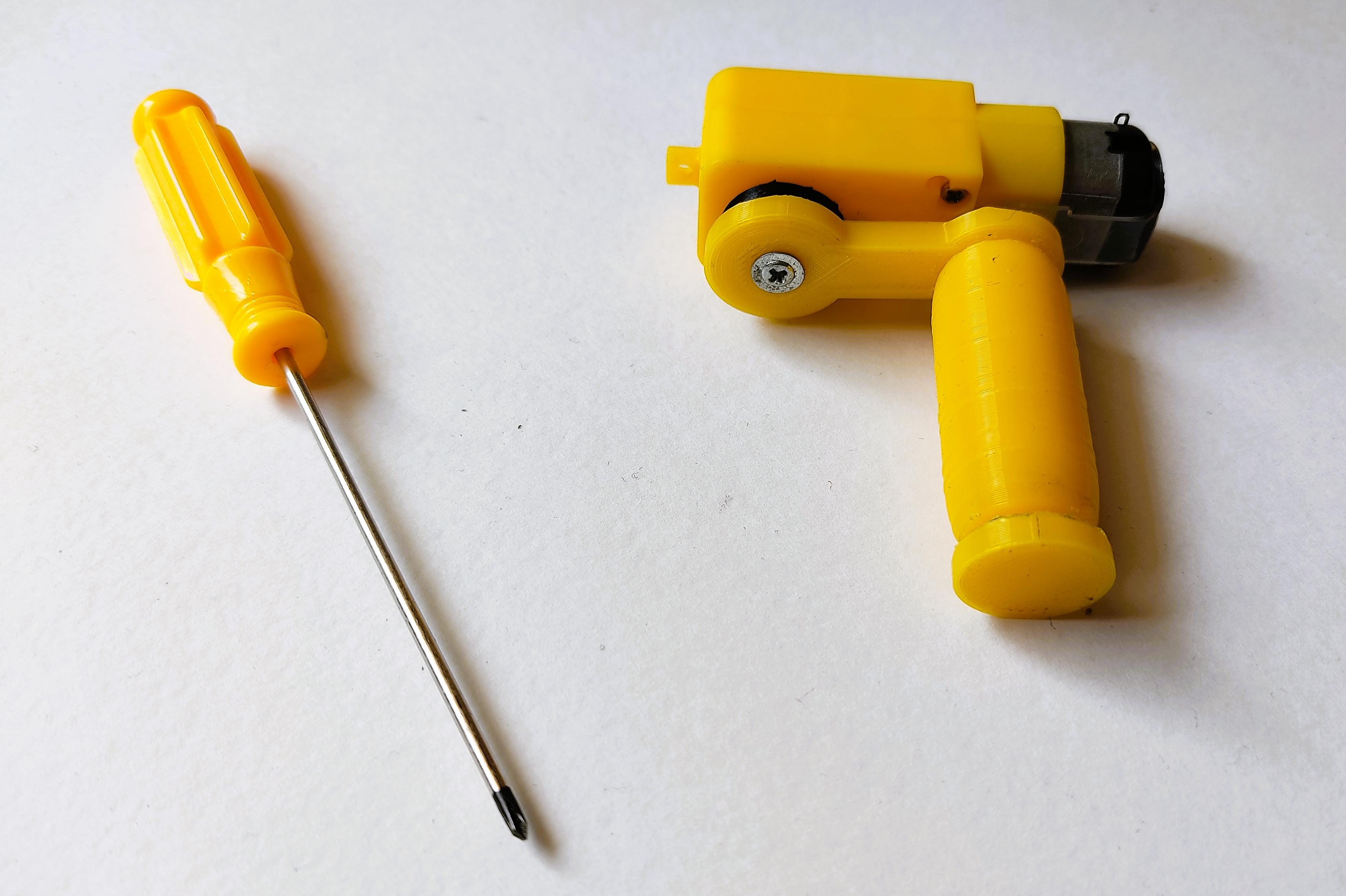
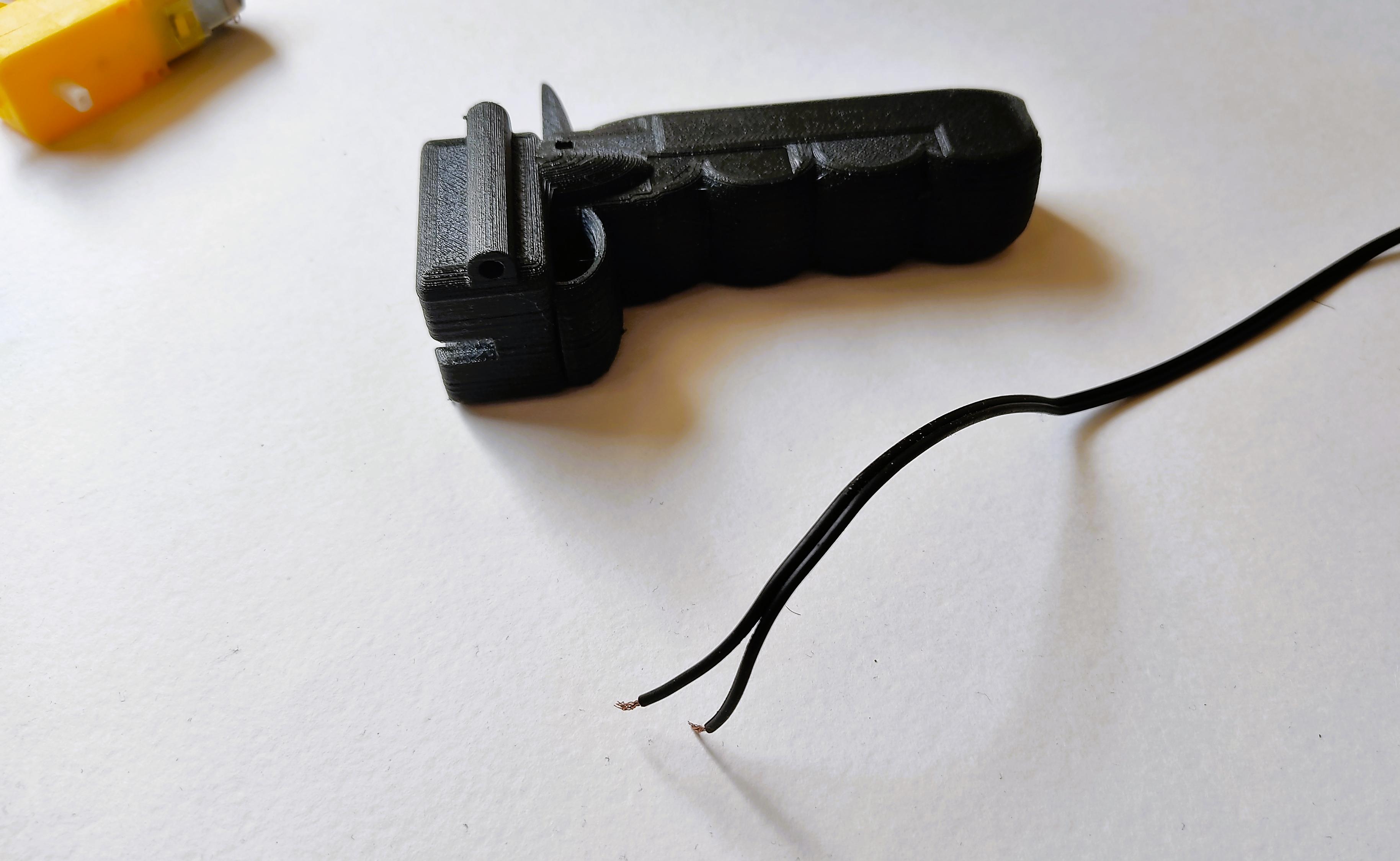
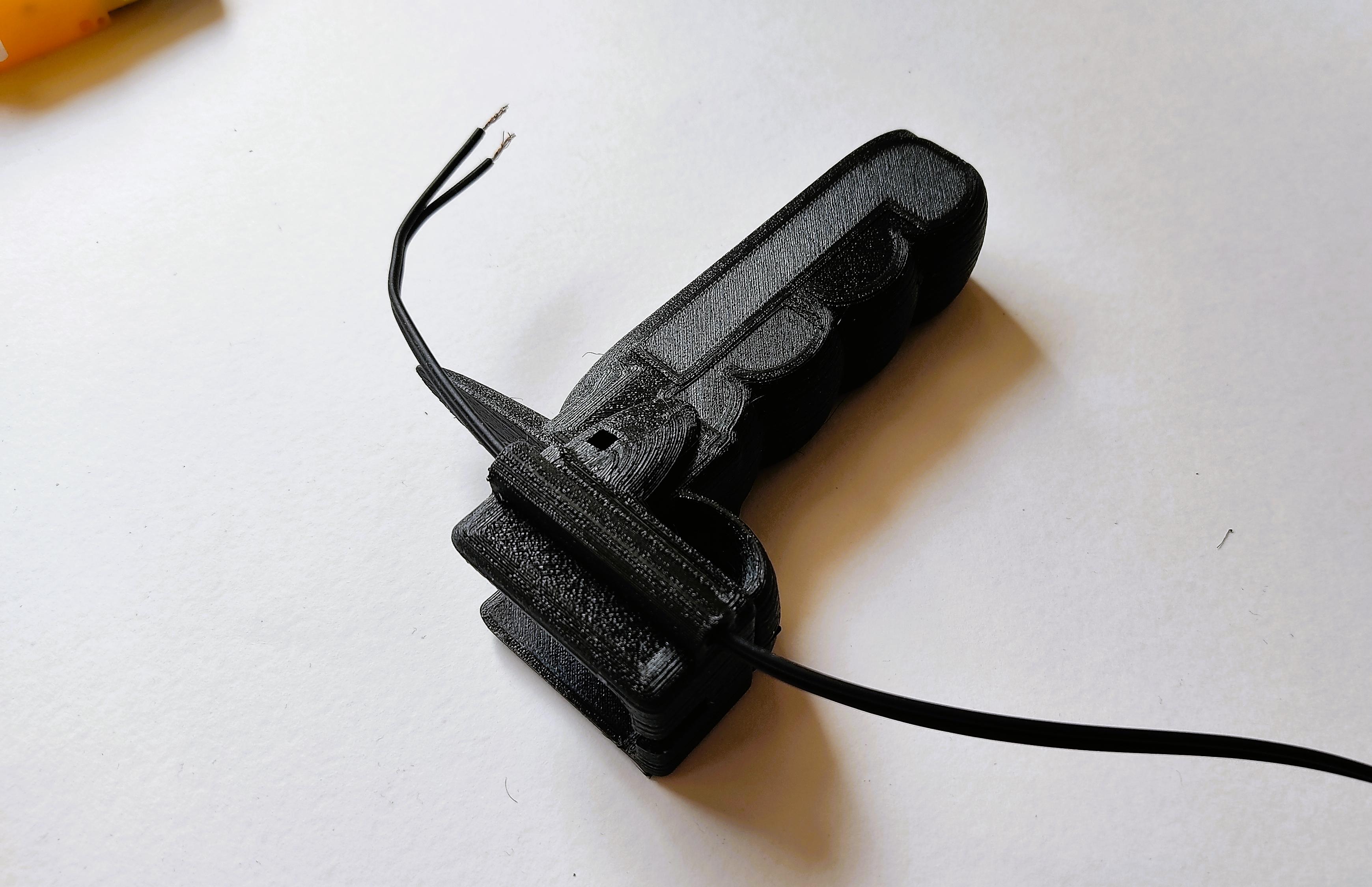
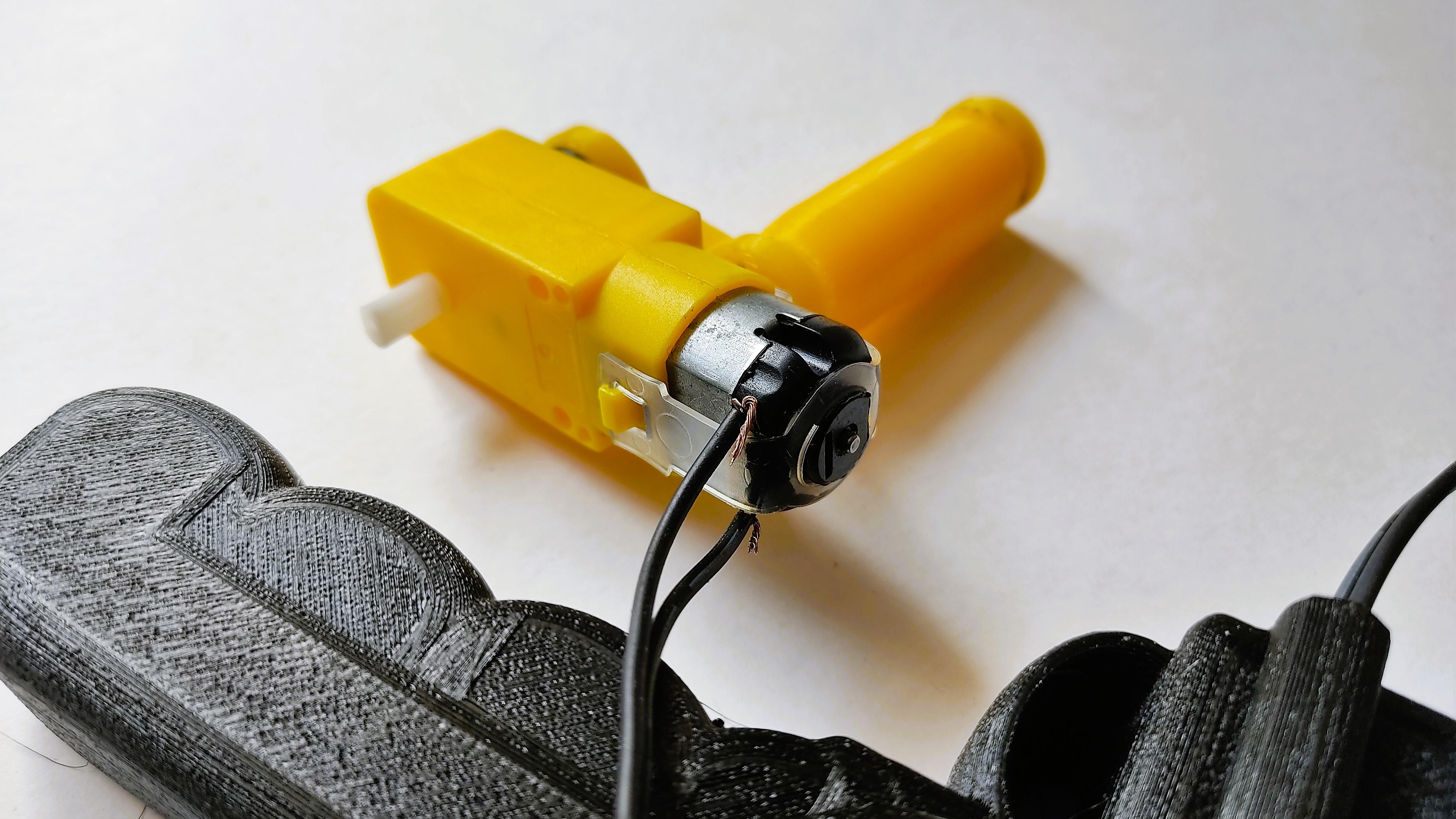
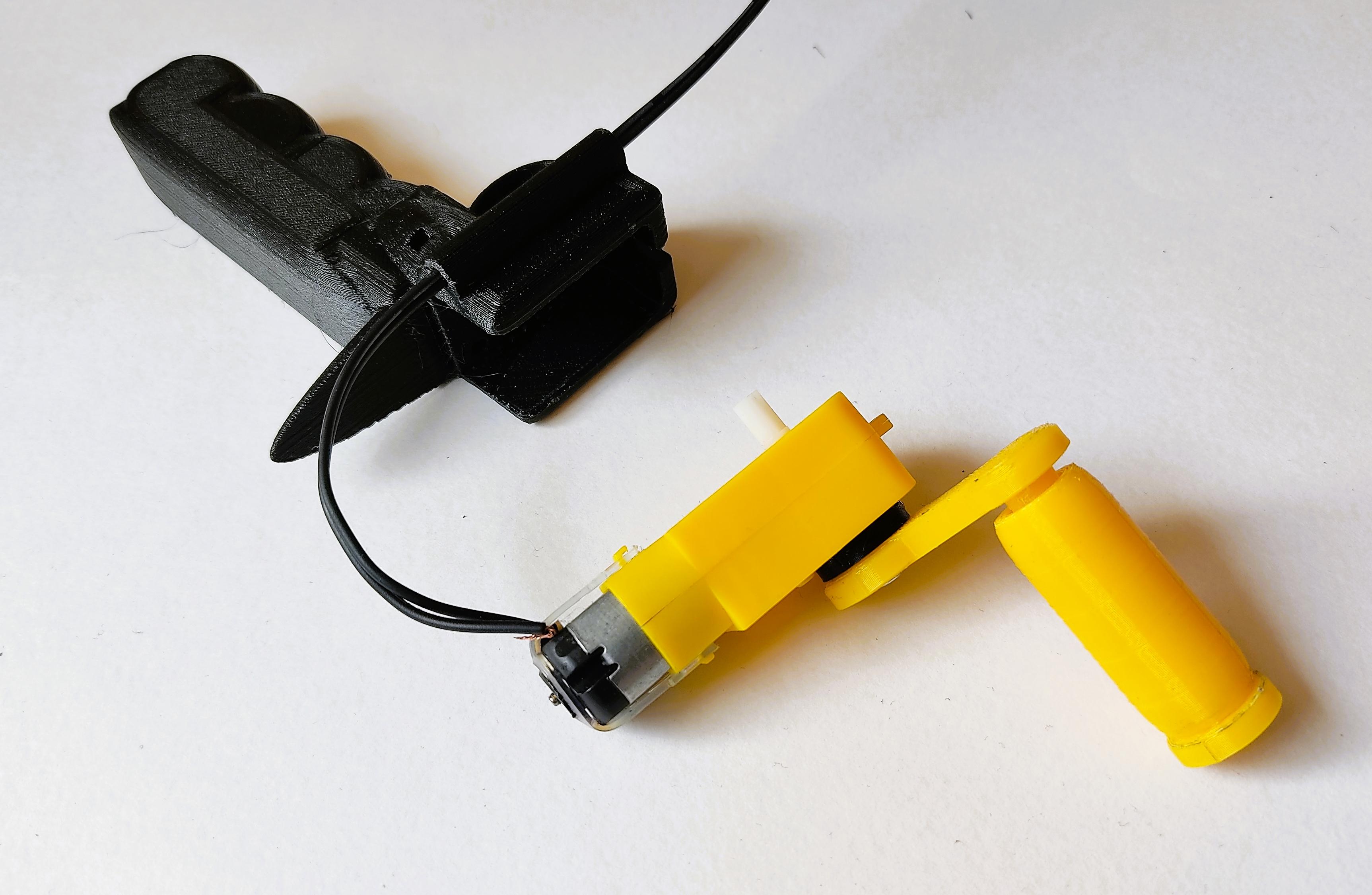
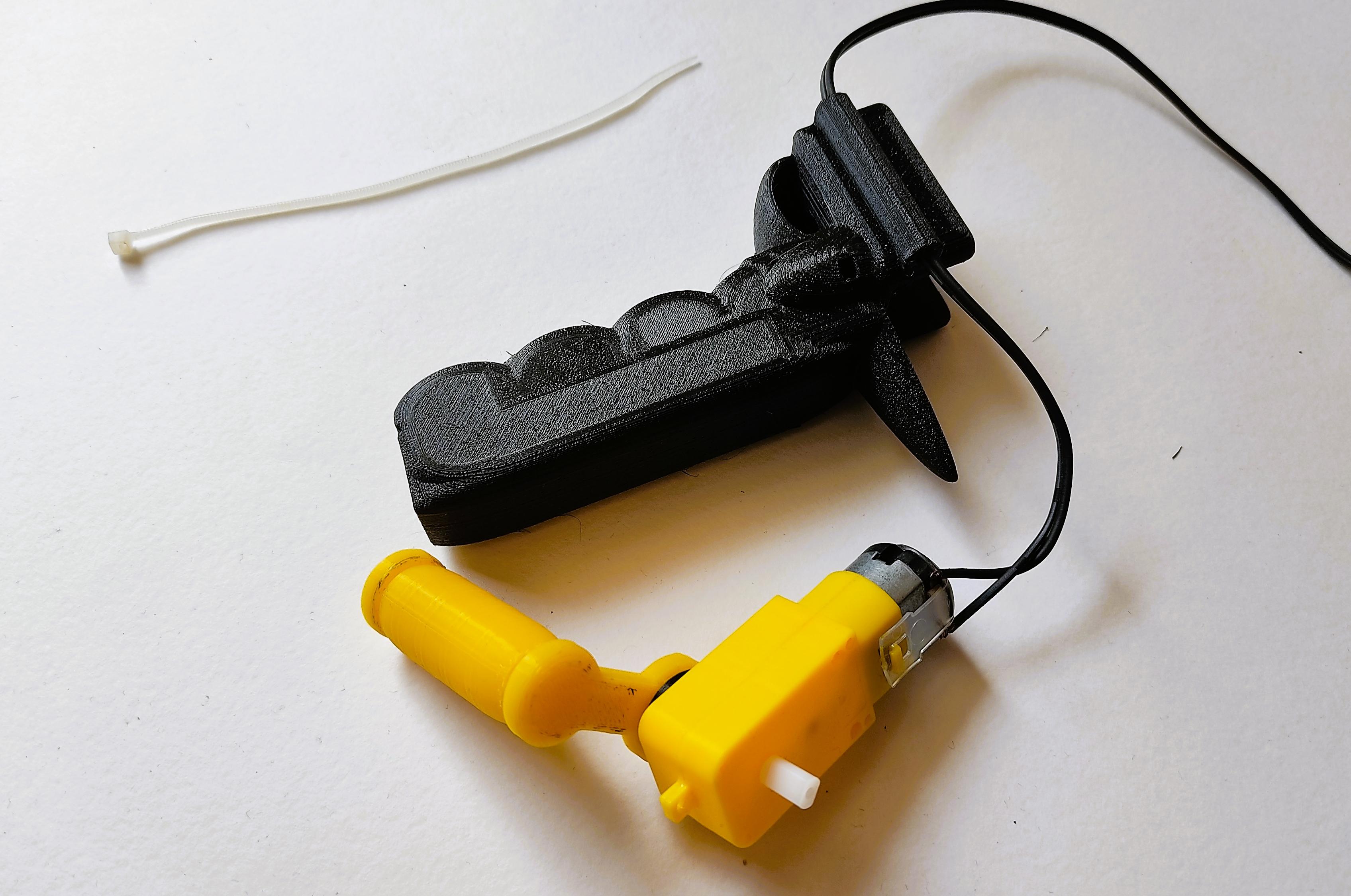
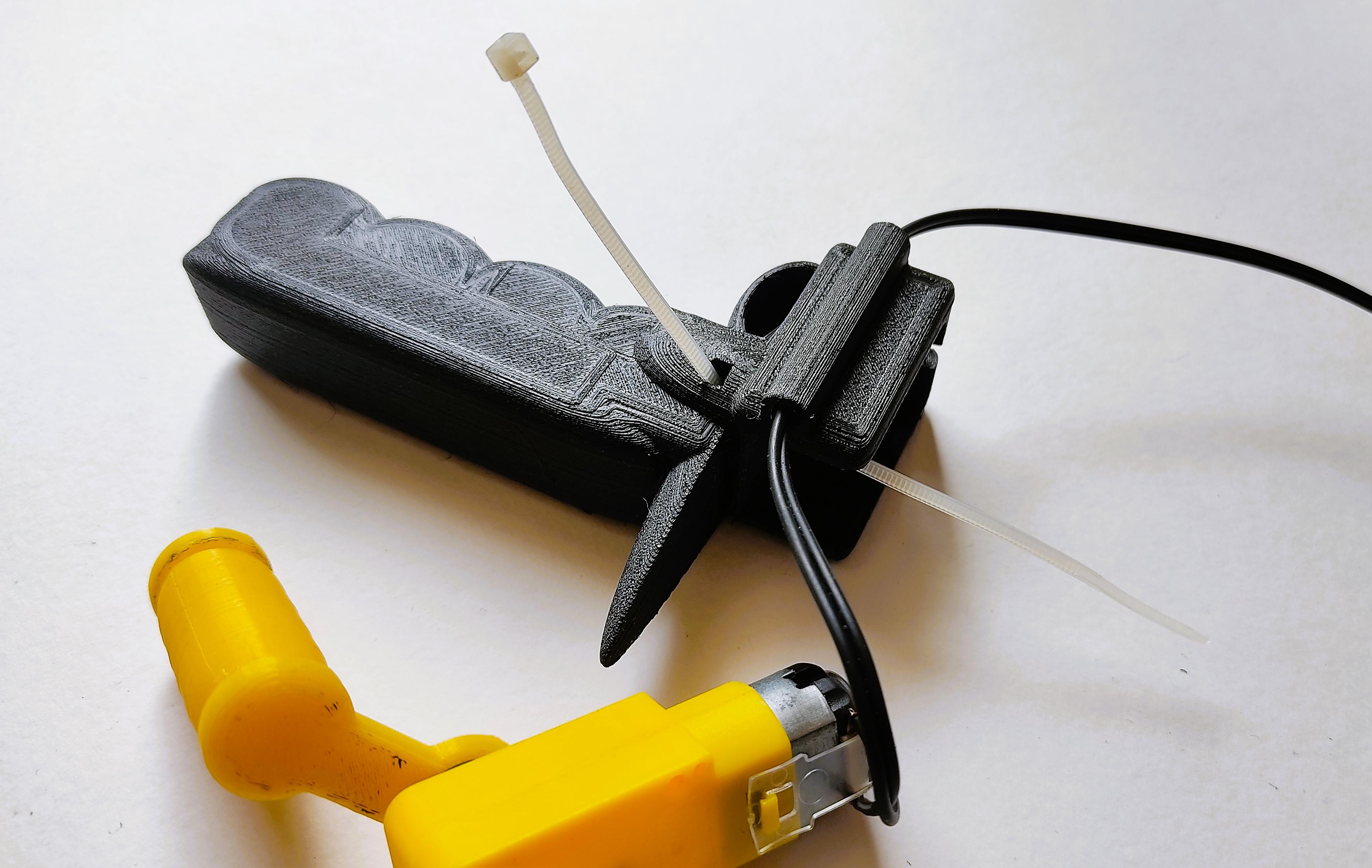
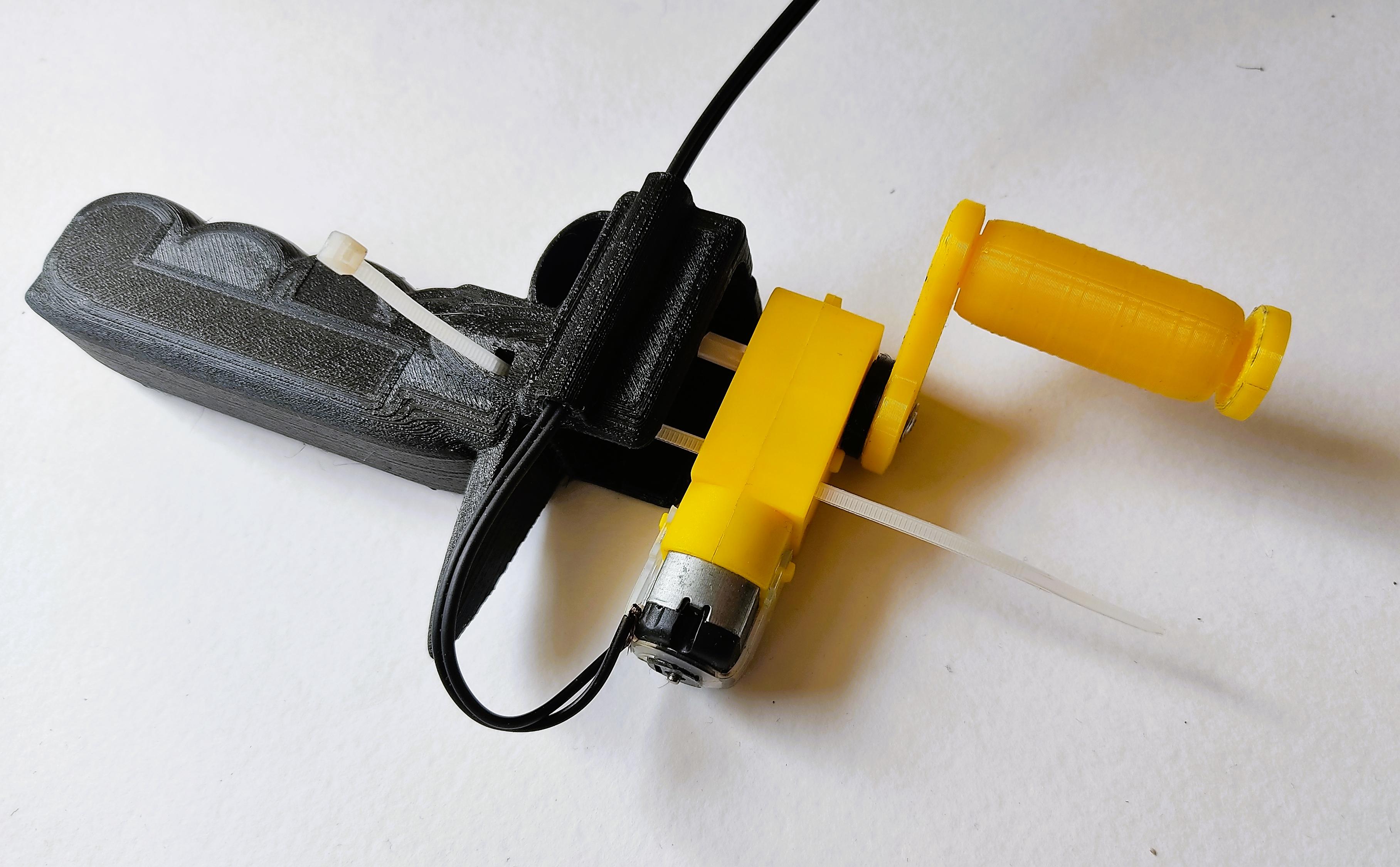
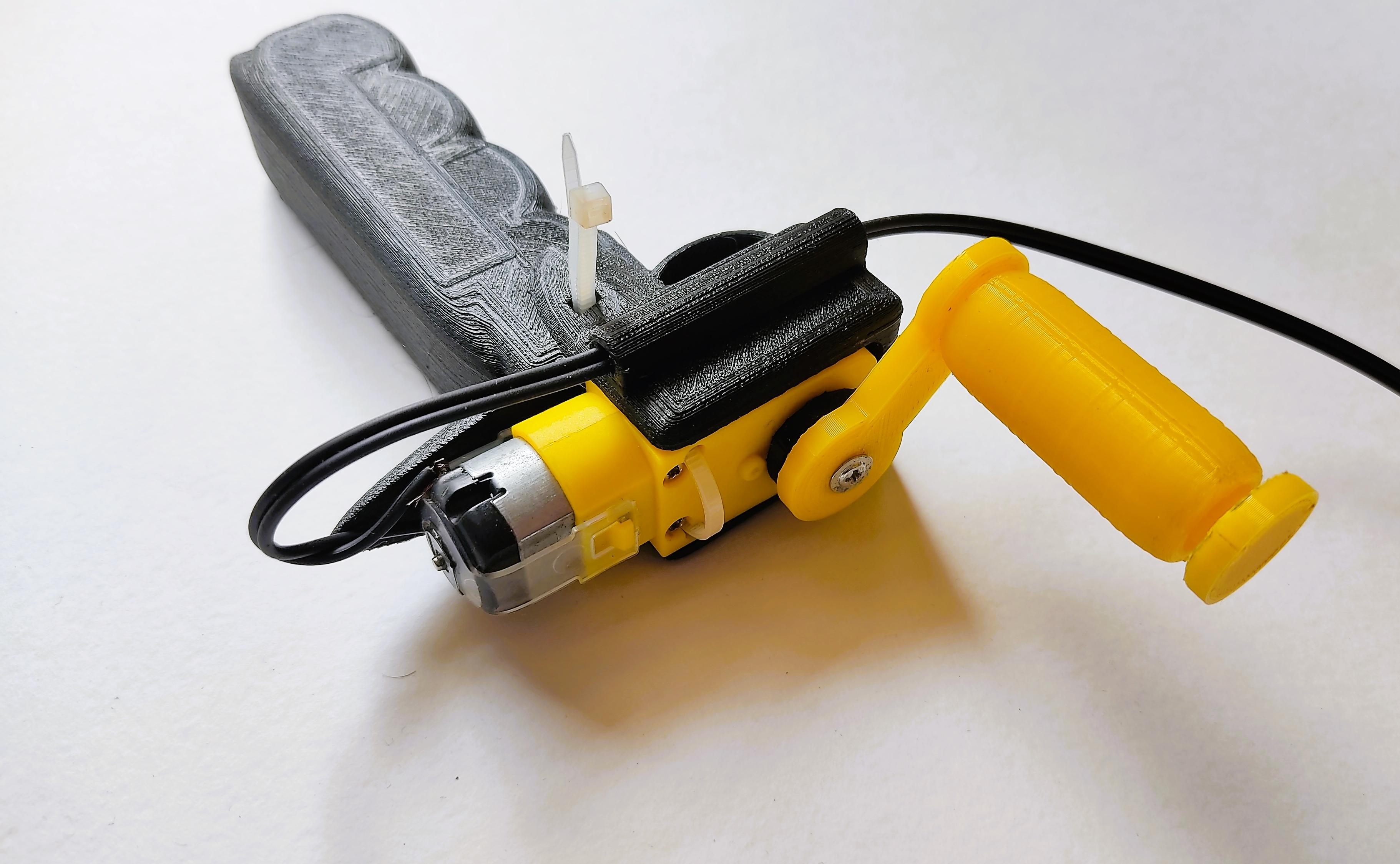
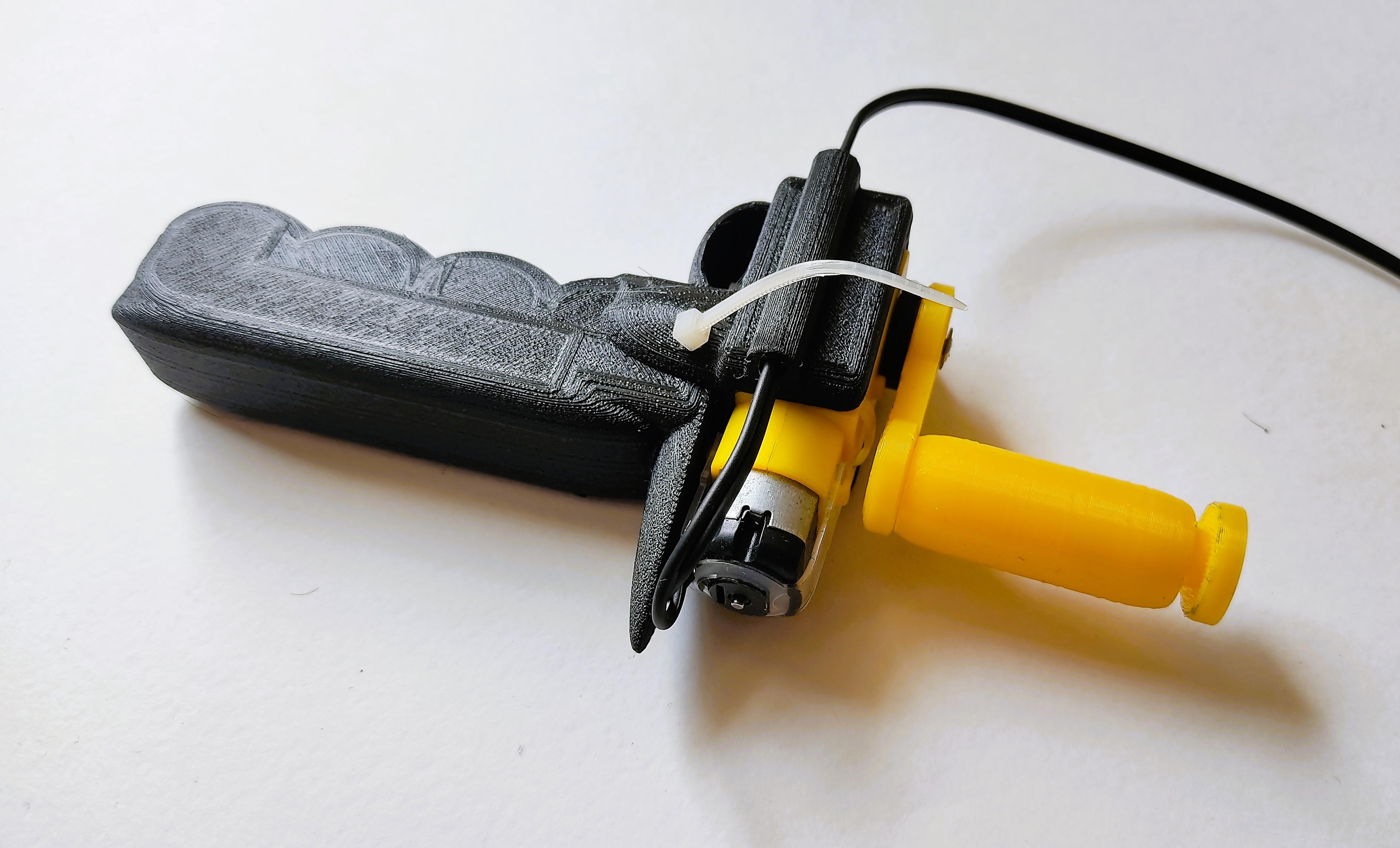
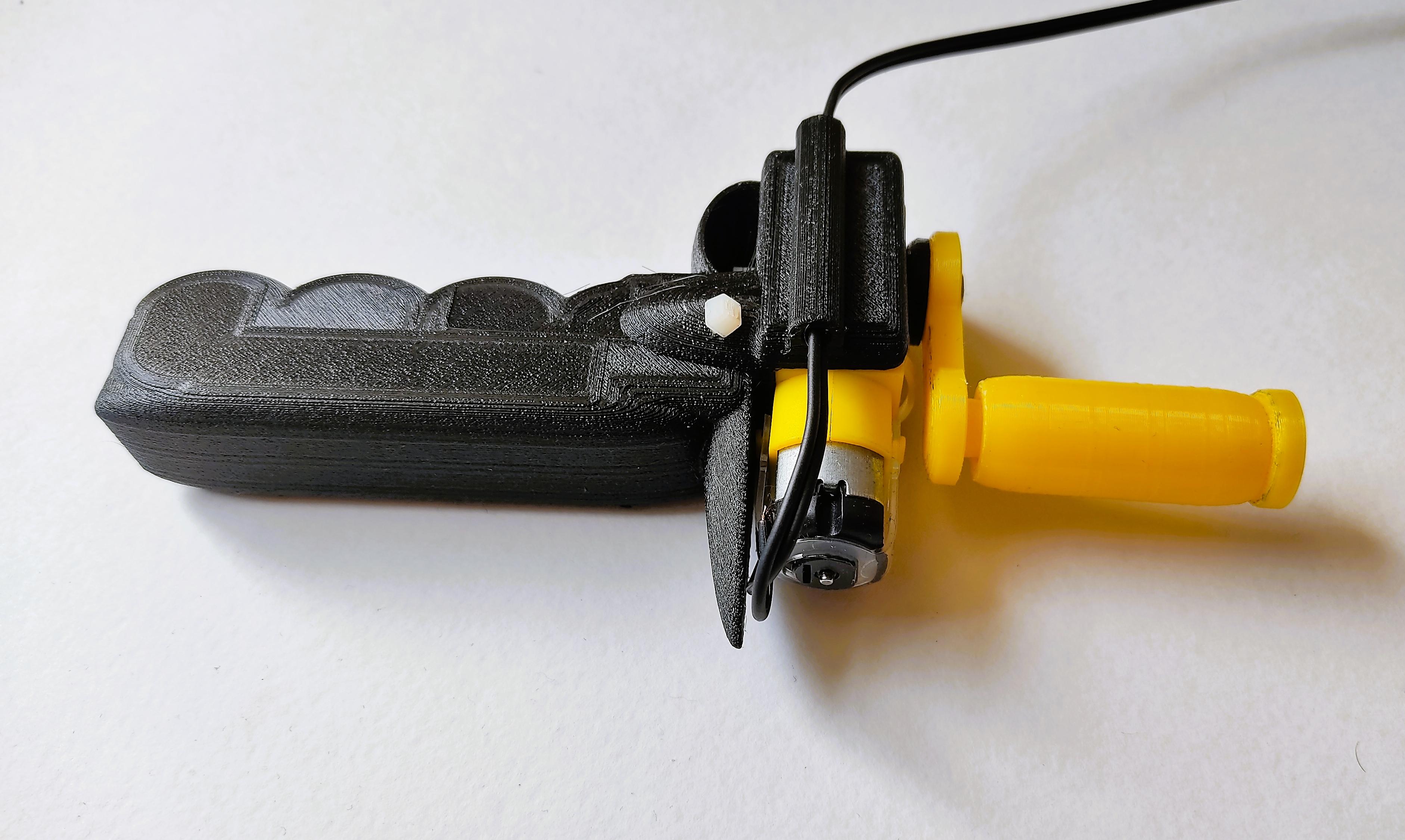
To assemble this new Hand Dynamo, insert the gearbox's axle into the washer, and then, into the crank's hole. Fix them using a screw. Then, insert the cable through the tunnel, and connect the wires to the motor pins.
Insert a zip-tie trough the hole in the handle. Then, insert the end of the zip-tie through the respective holes in the gearbox, bringing the end to the other hole in the handle. Close the zip-tie, pull until the gearbox is firmly attached, and them cut the remaining part of the zip-tie.
Pinky 1: Motor Case
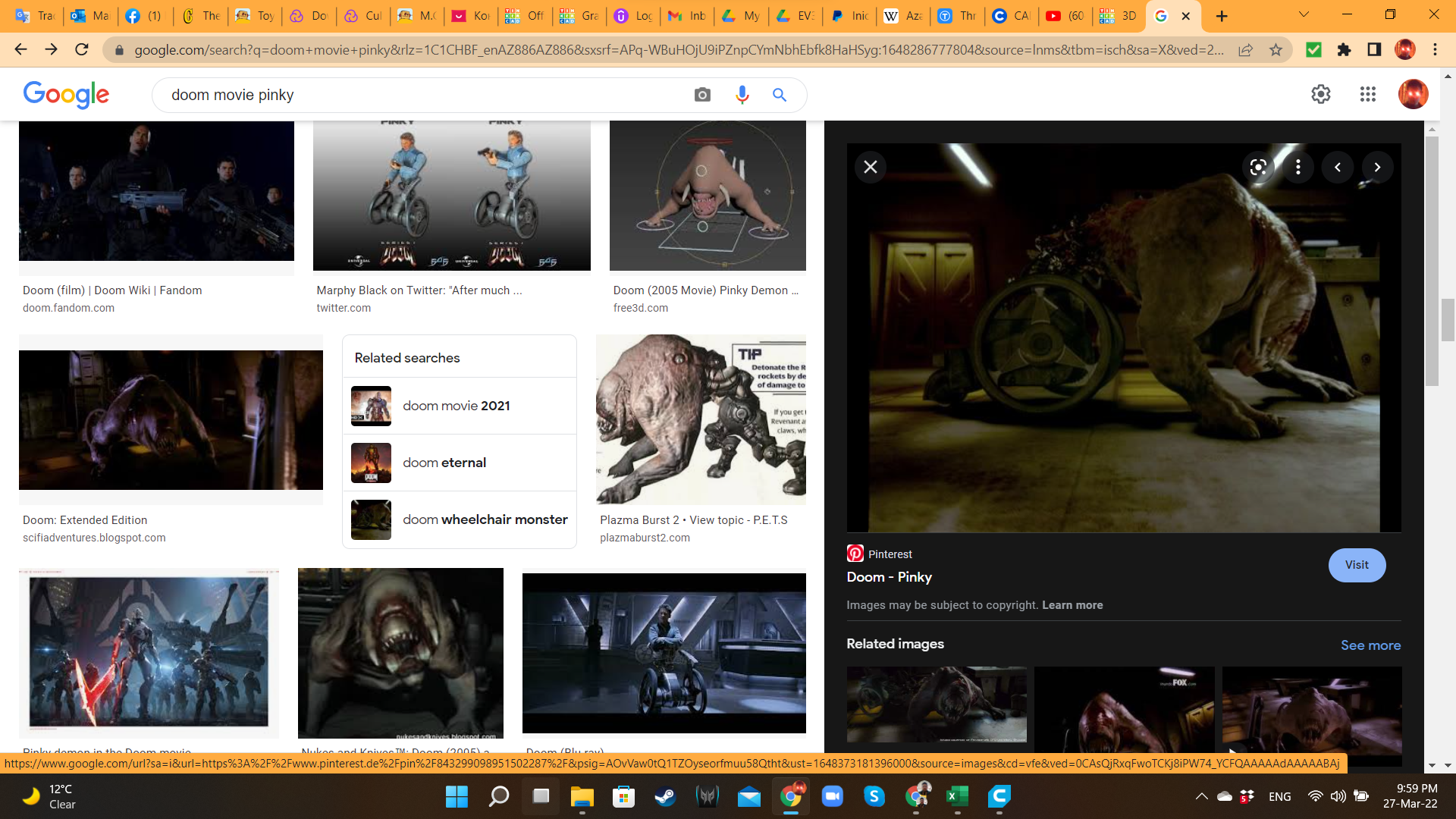
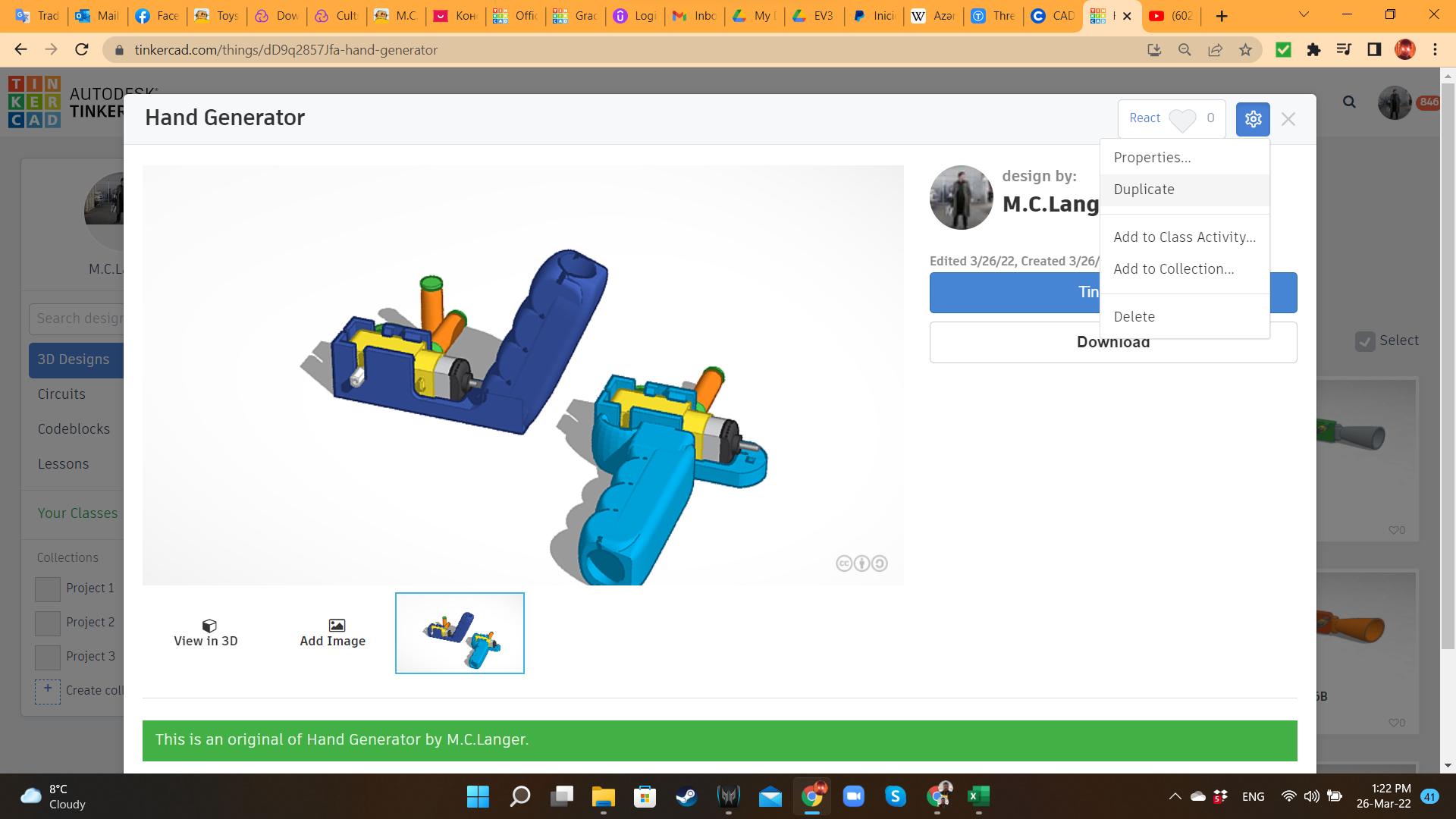
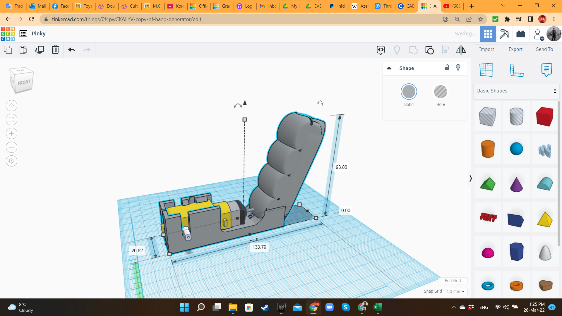
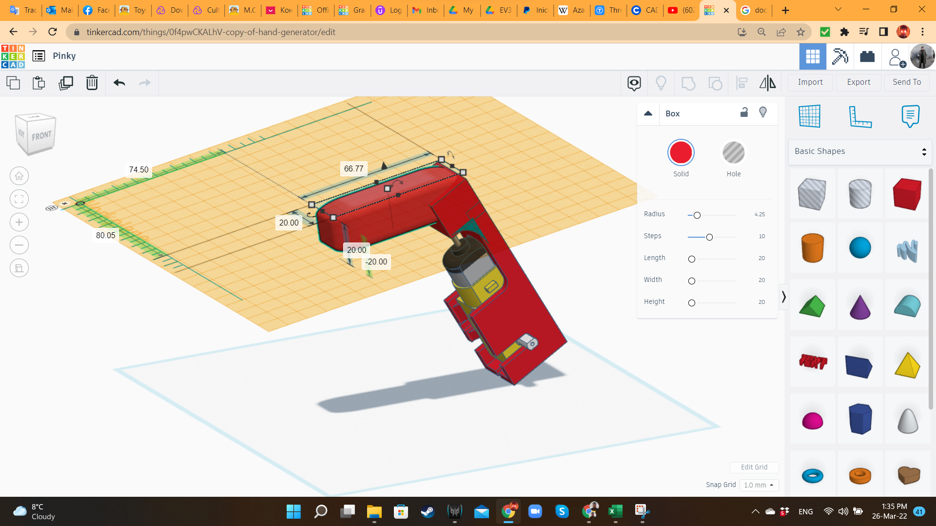
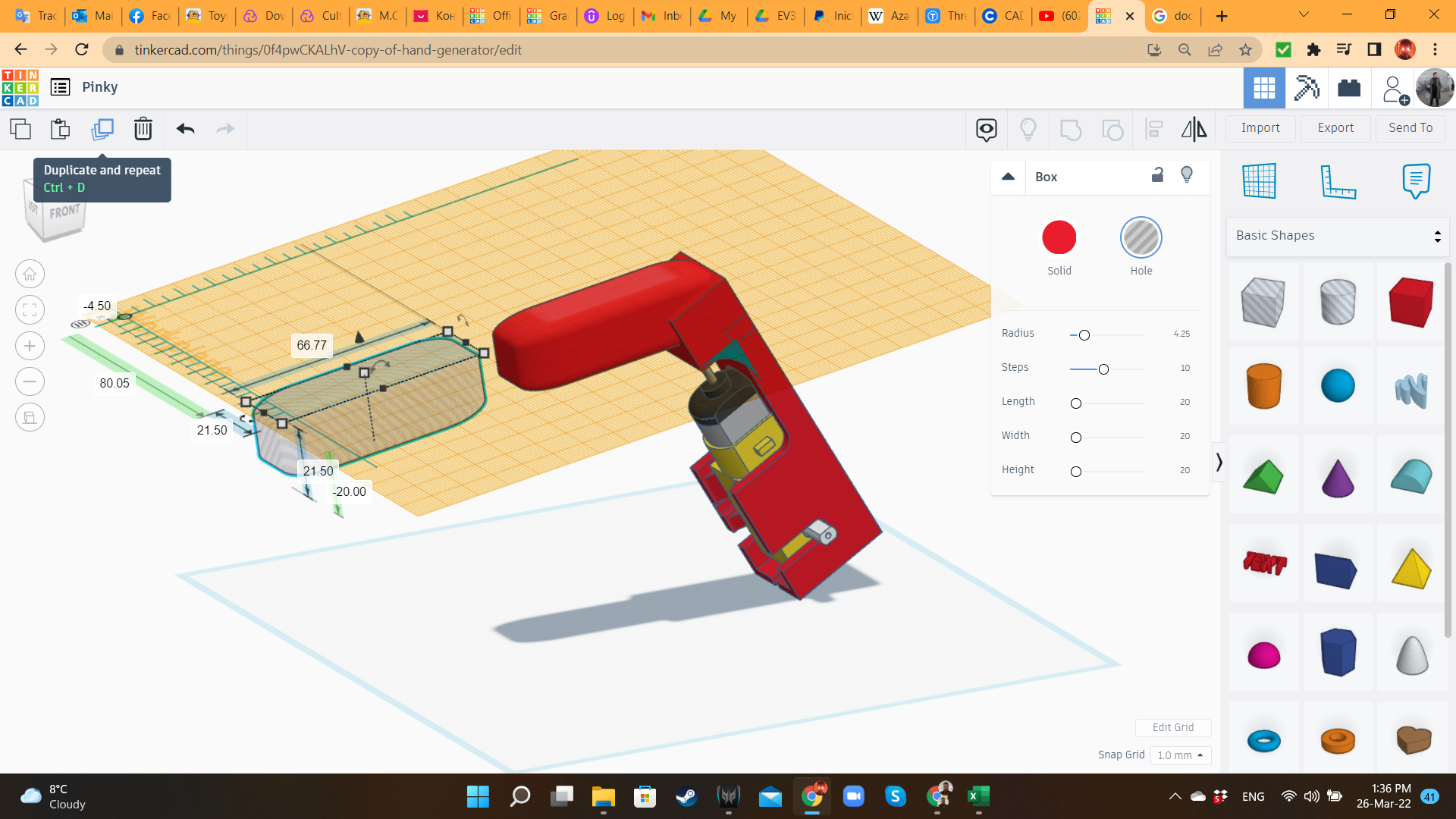
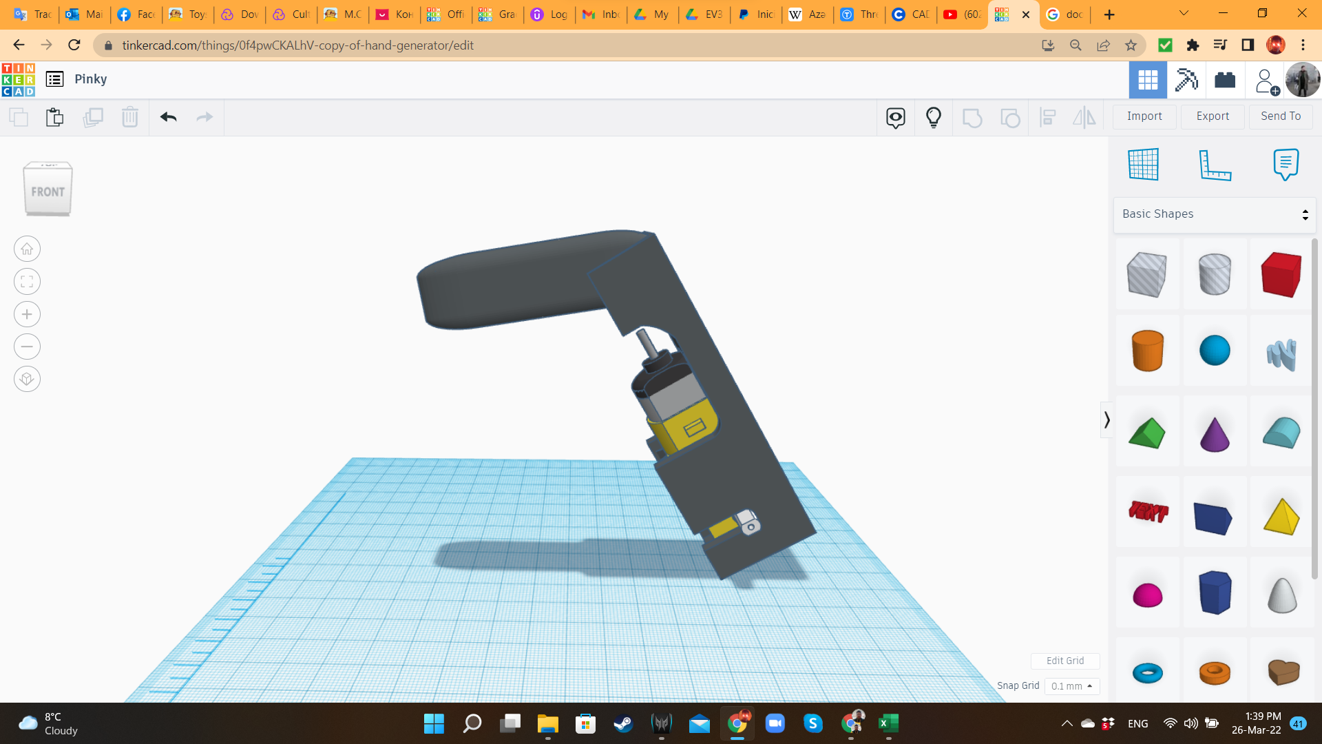
Let's start with Pinky! First, I searched in Google some images from this movie monster, to know the direction I would take with the design. If you saw the movie, probably you remember that Pinky in a was a scientist, with a wheelchair-like cybernetic implant for locomotion. When he mutated into a horrible creature, the wheelchair kept being a part of that monster. This motor case will be that: the wheelchair implant.
I went to my Dashboard, and duplicated the design I created for the first Hand Dynamo (handgun). I rotated the design more or less 105 degrees, removed the handle, and replaced it with a Box with some radius to soften the edges. Then, I duplicated that box, increased the size in a 105%, and transformed it into a hole. That hole would be in the rear part of the Beast.
Pinky 2: Wheel/Crank
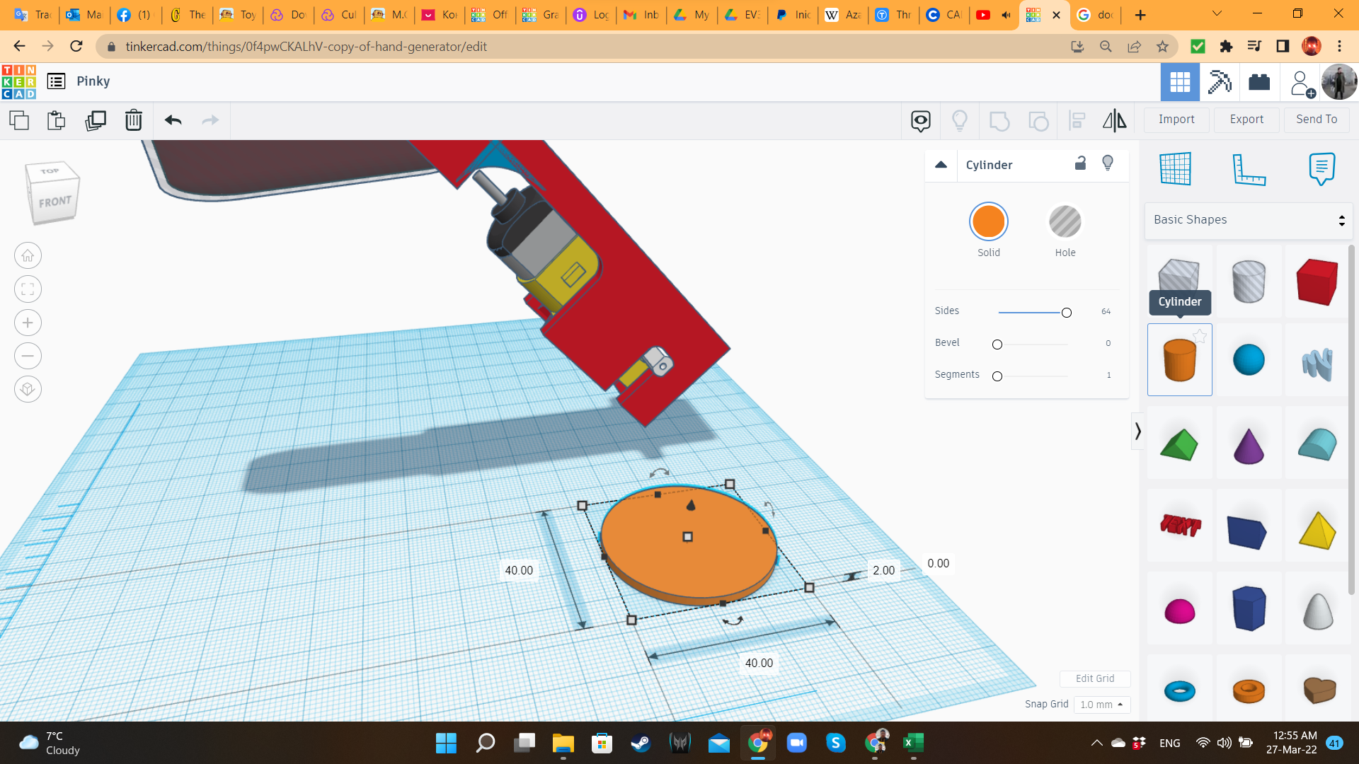
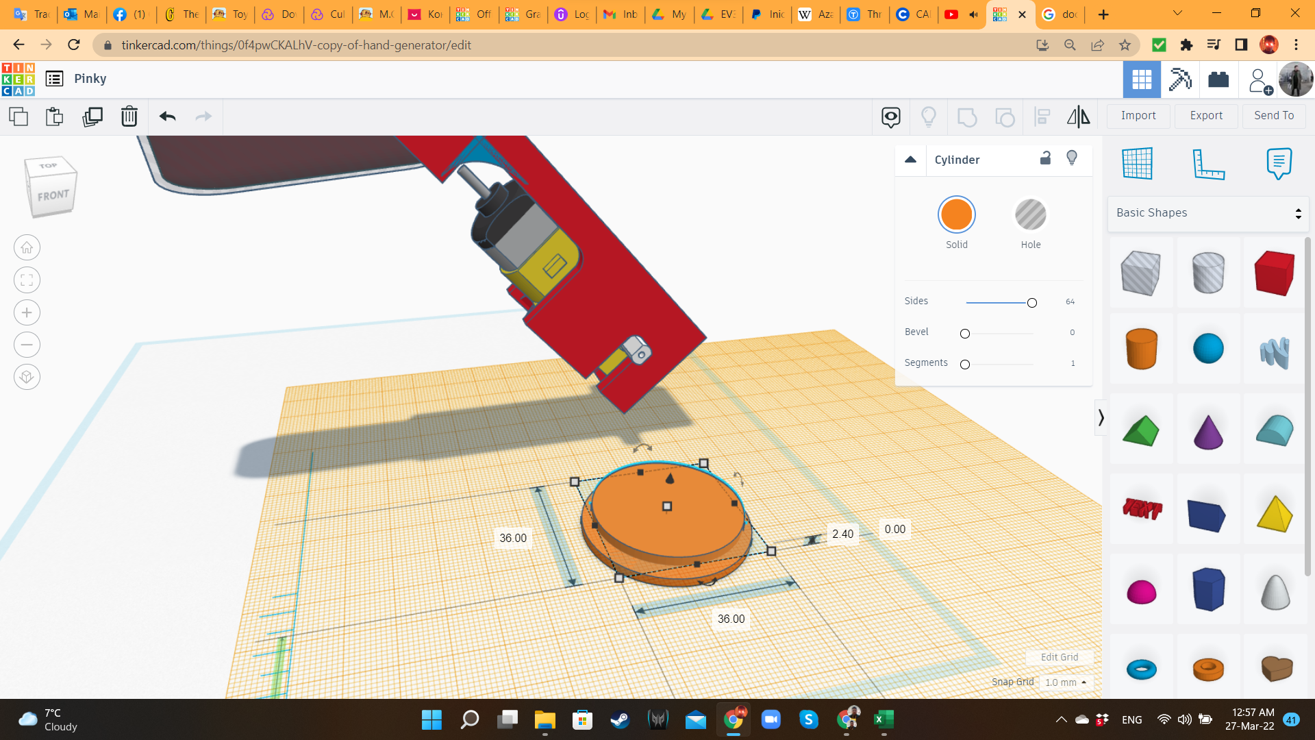
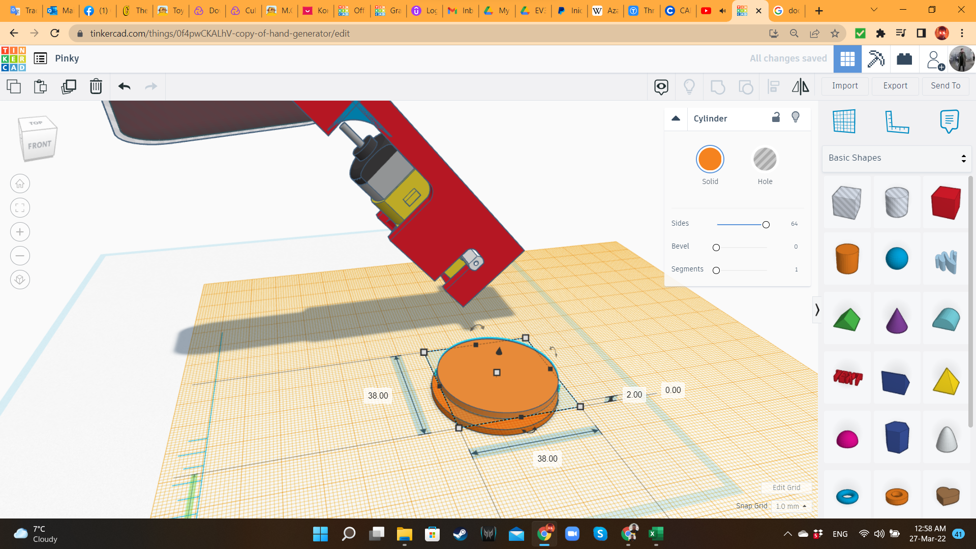
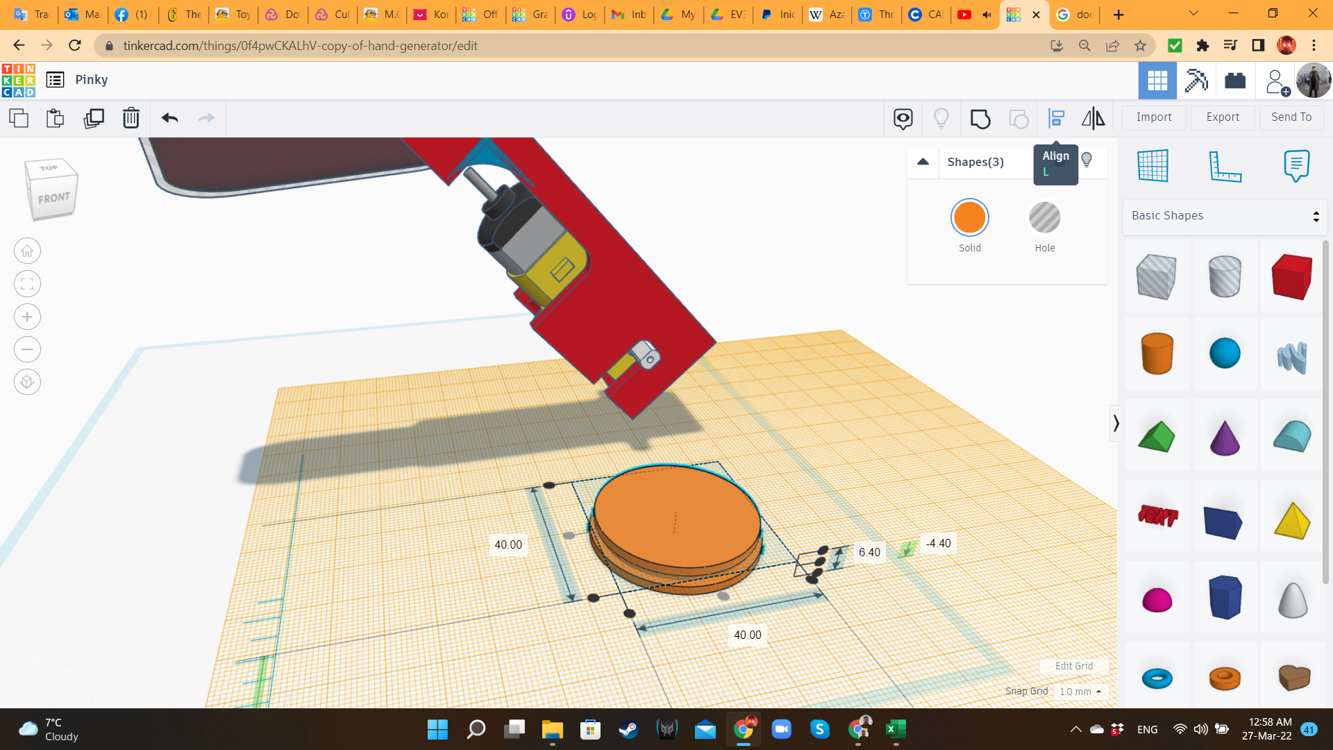
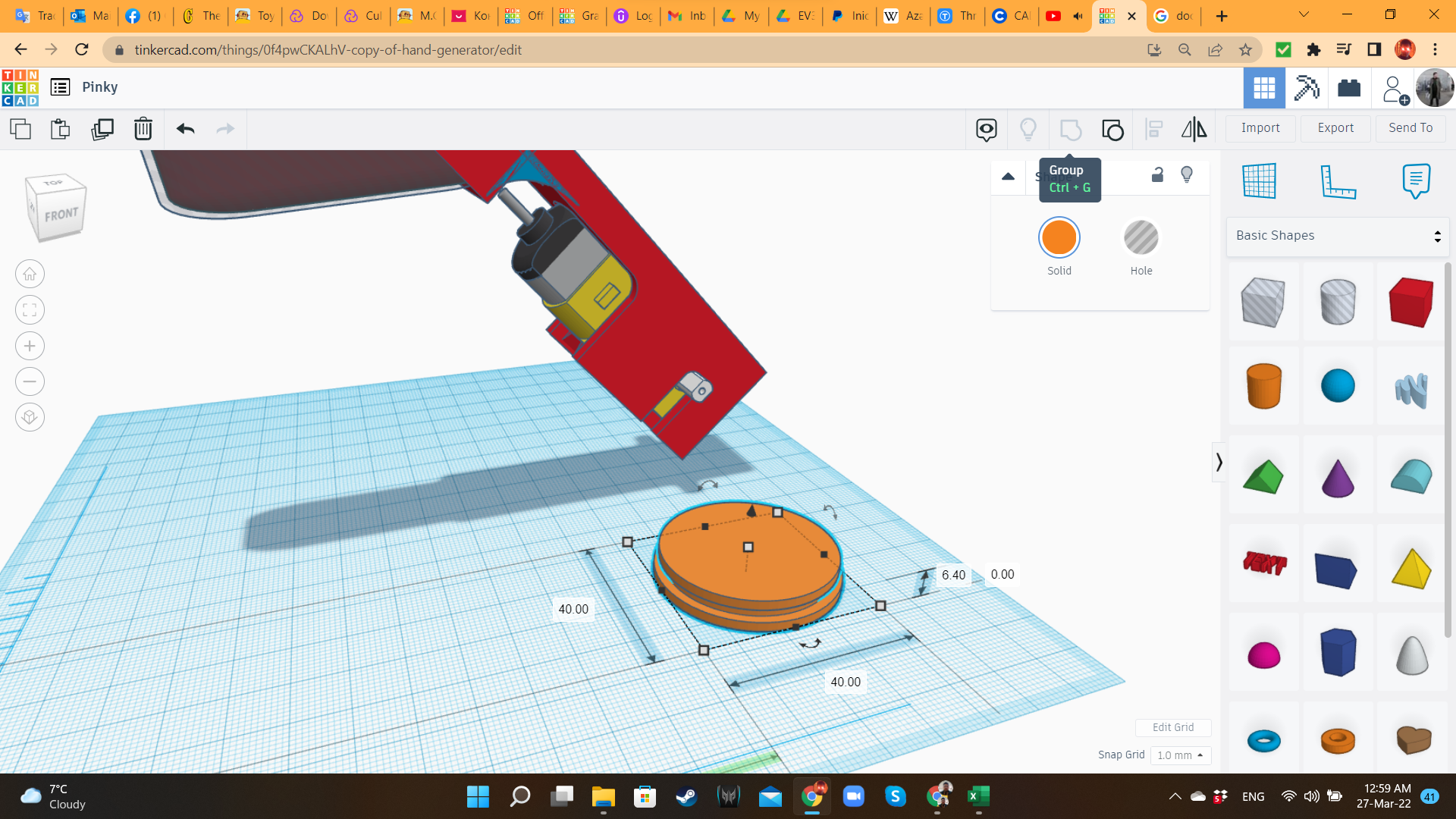
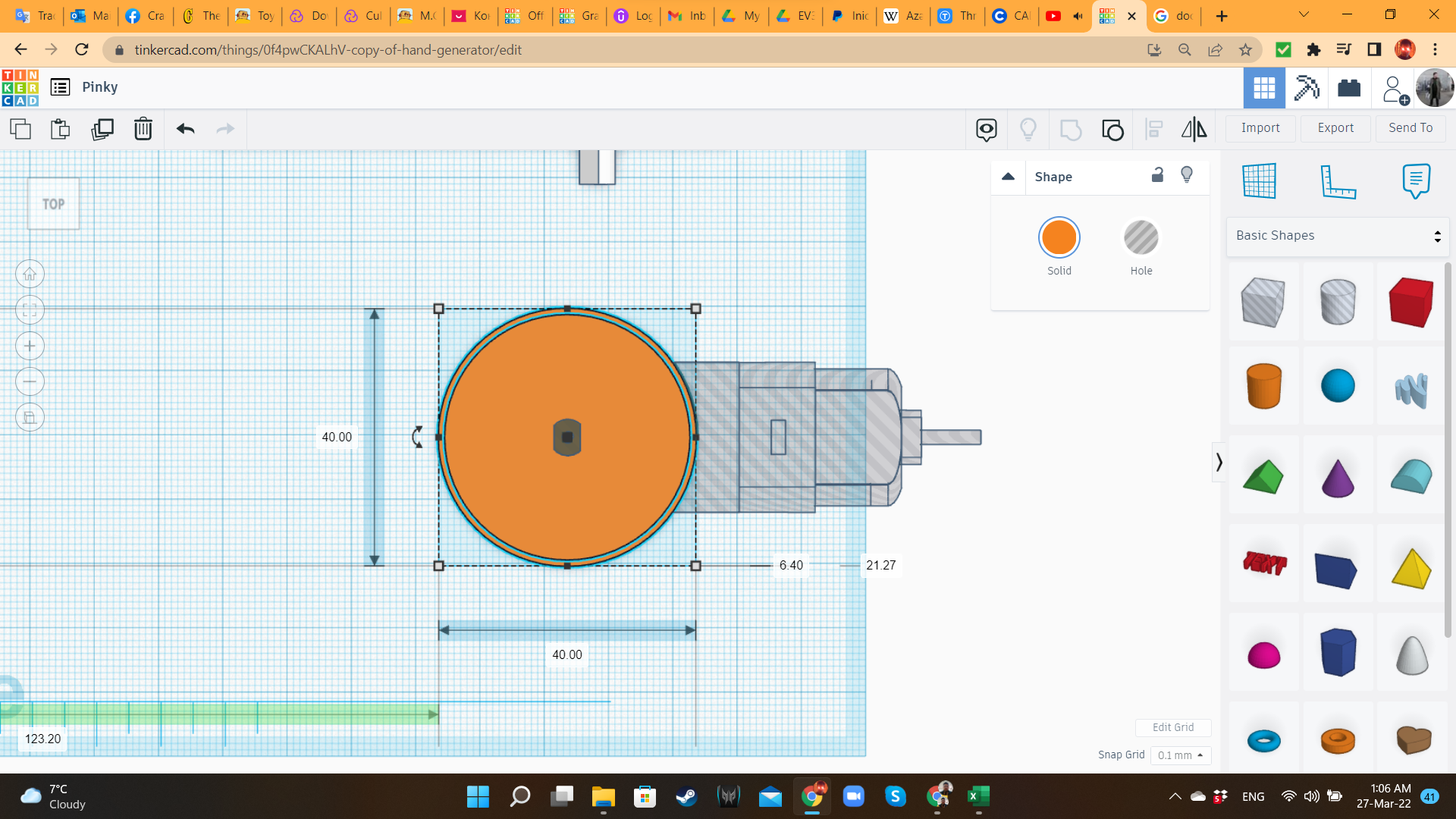
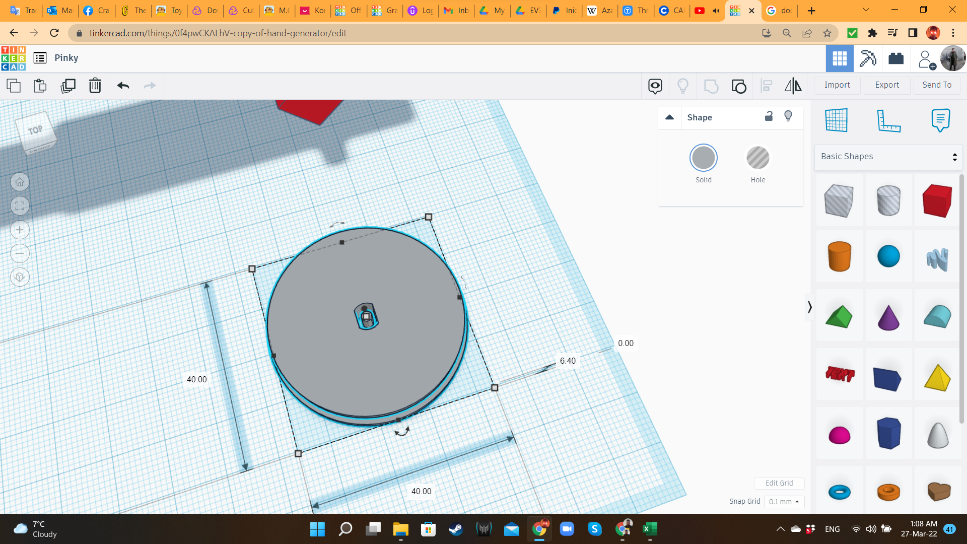
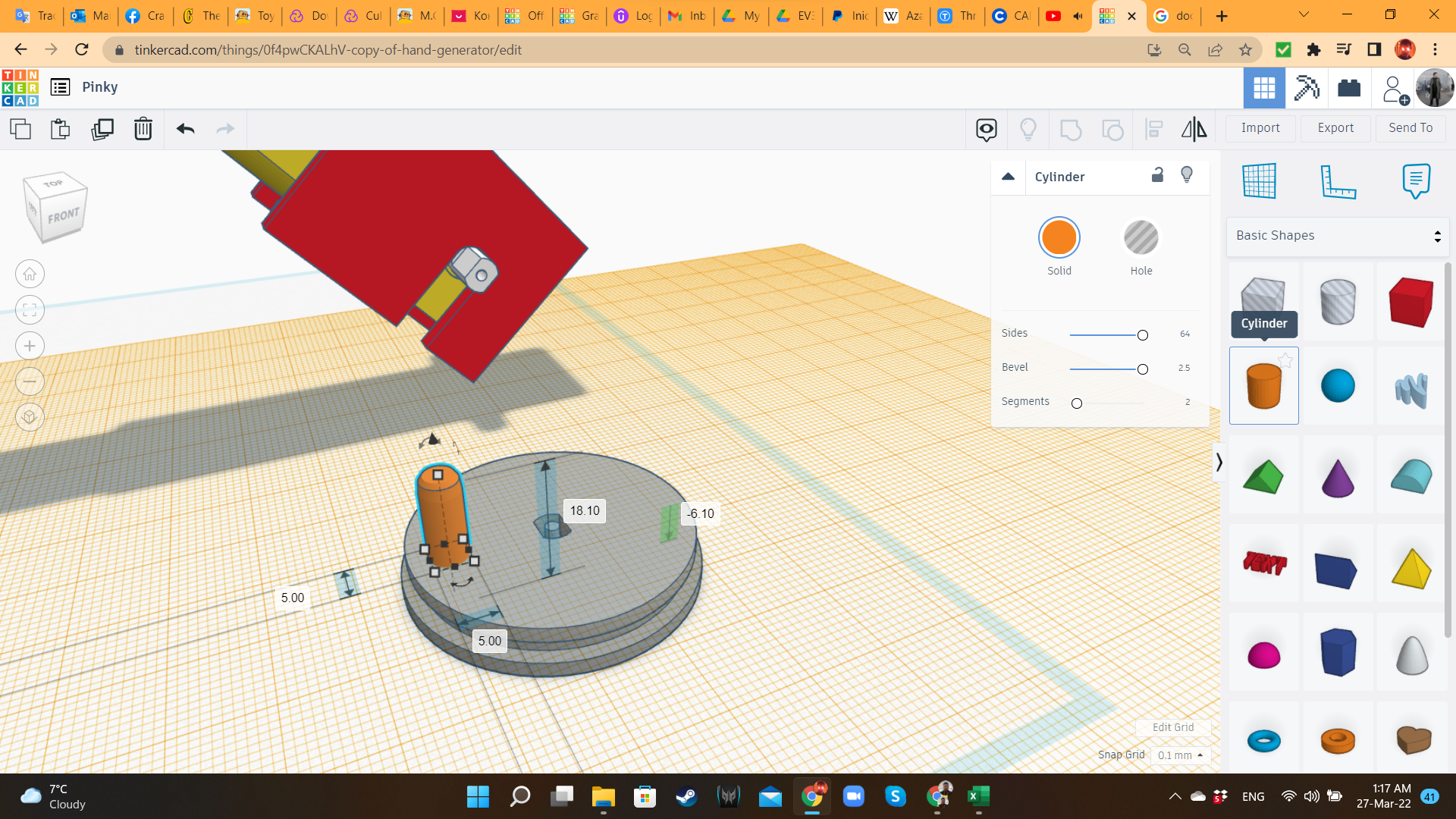
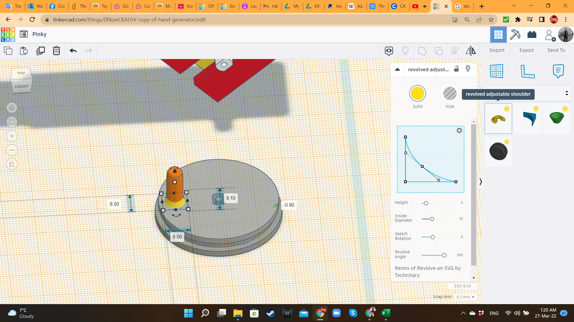
Using concentric cylinders, I created the wheels, where the rubber rings would be inserted as tires. For the crank, I added a cylinder and a revolved adjustable shoulder. Then, I imported again the Gearmotor's STL at 105% scale, aligned the axle to the center of the wheel, and grouped it.
Pinky 3 Transmission Bar
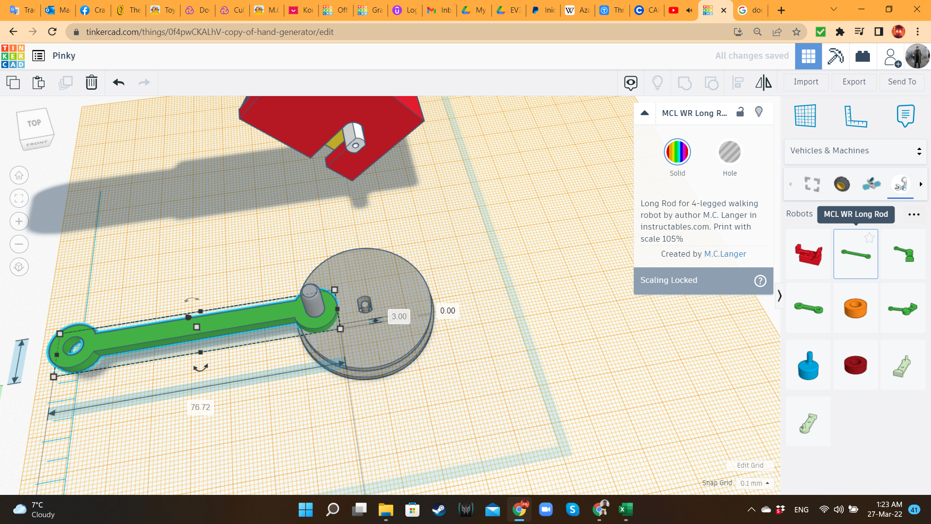
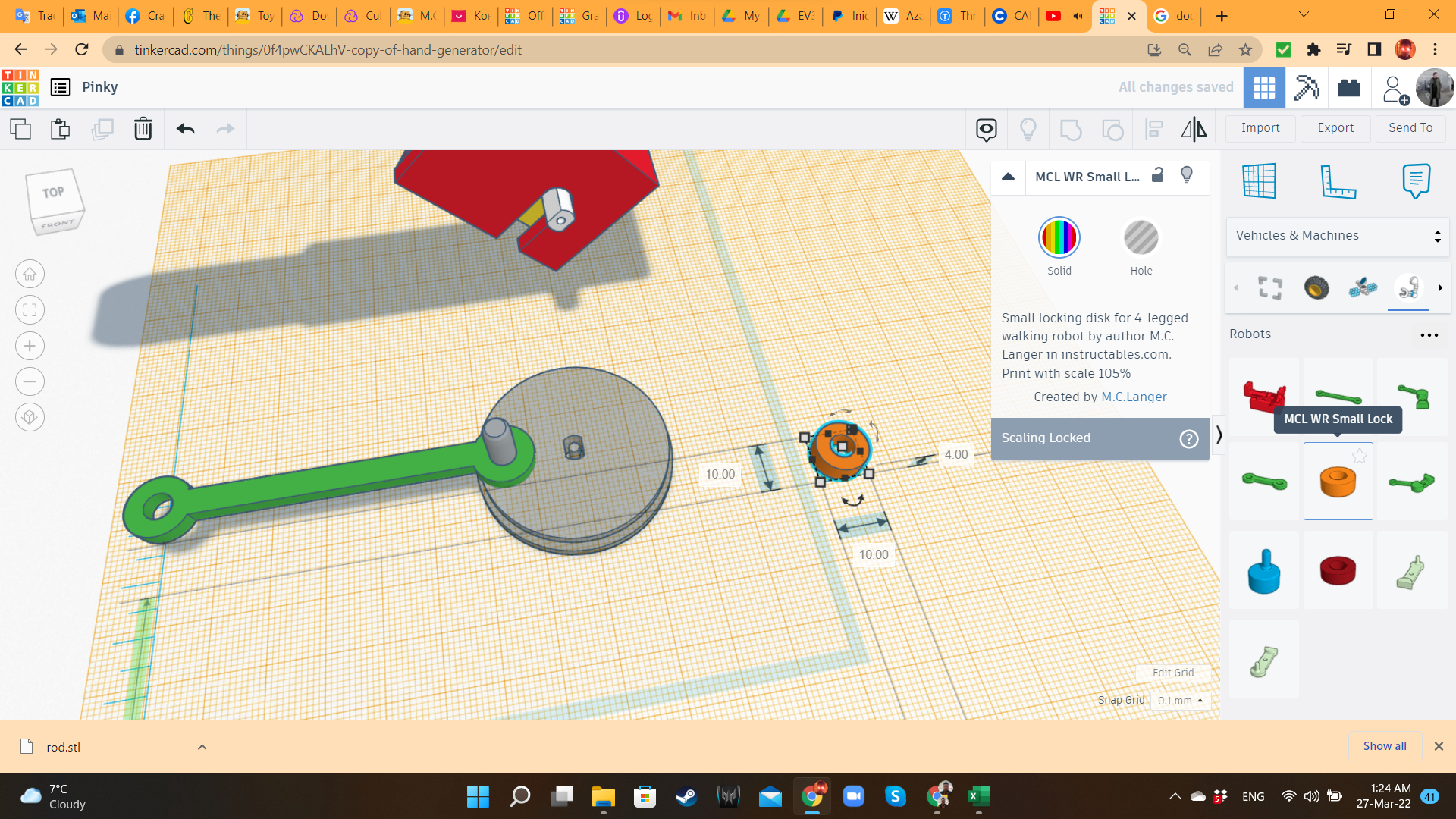
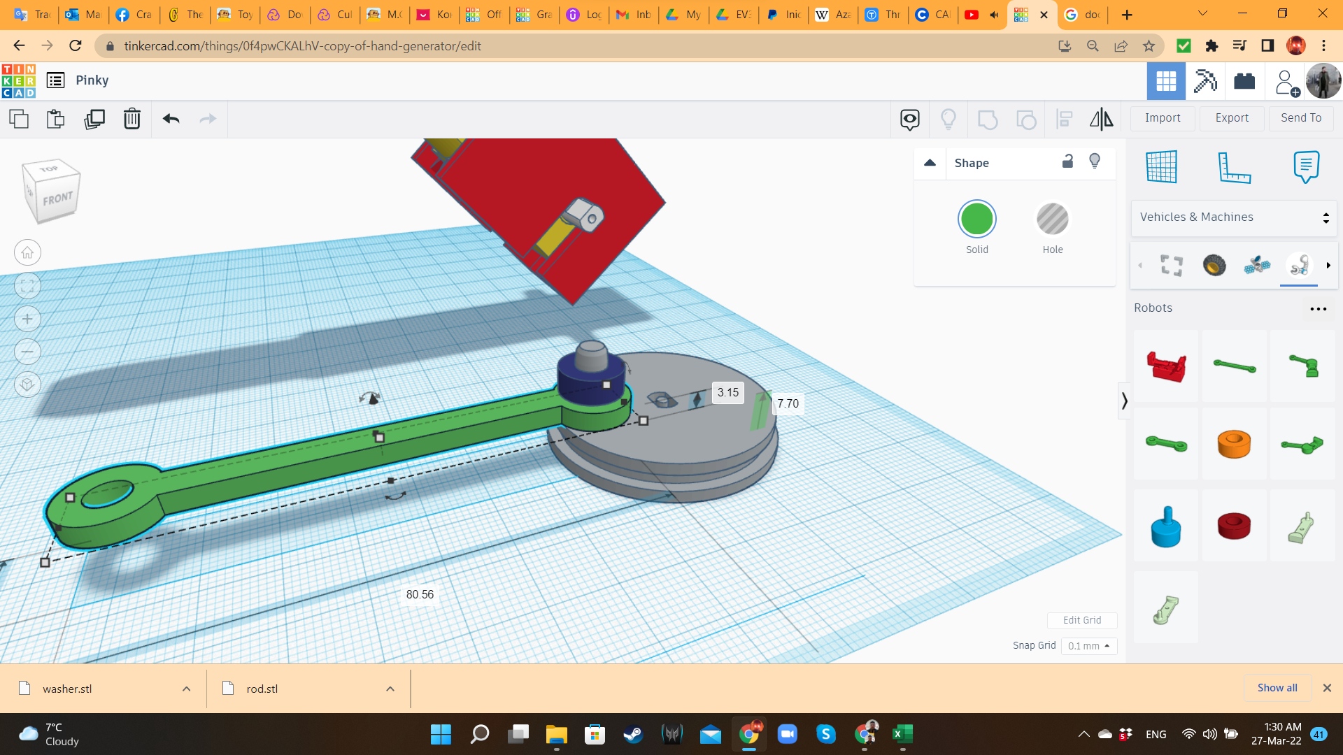
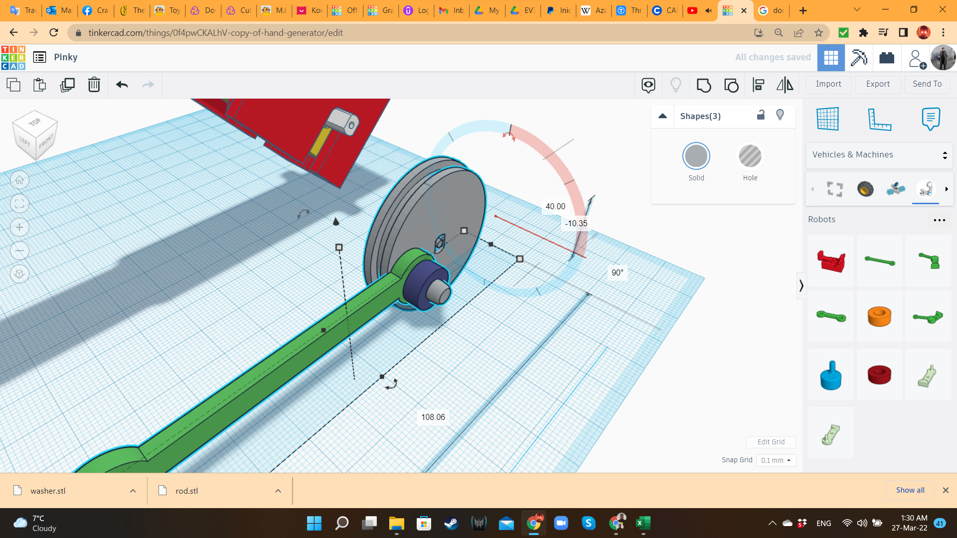
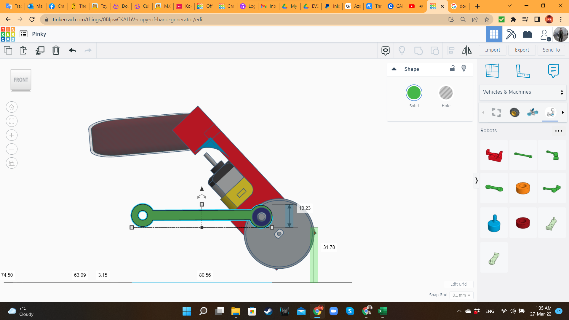
I brought a MCL WR Long Rod and a Washer from the "Vehicles and machines/robots" library, and adjusted them to the crank. Then I rotated this kit 90 degrees, and aligned it to the gearmotor's axle.
Pinky 4: Duplicating the Components
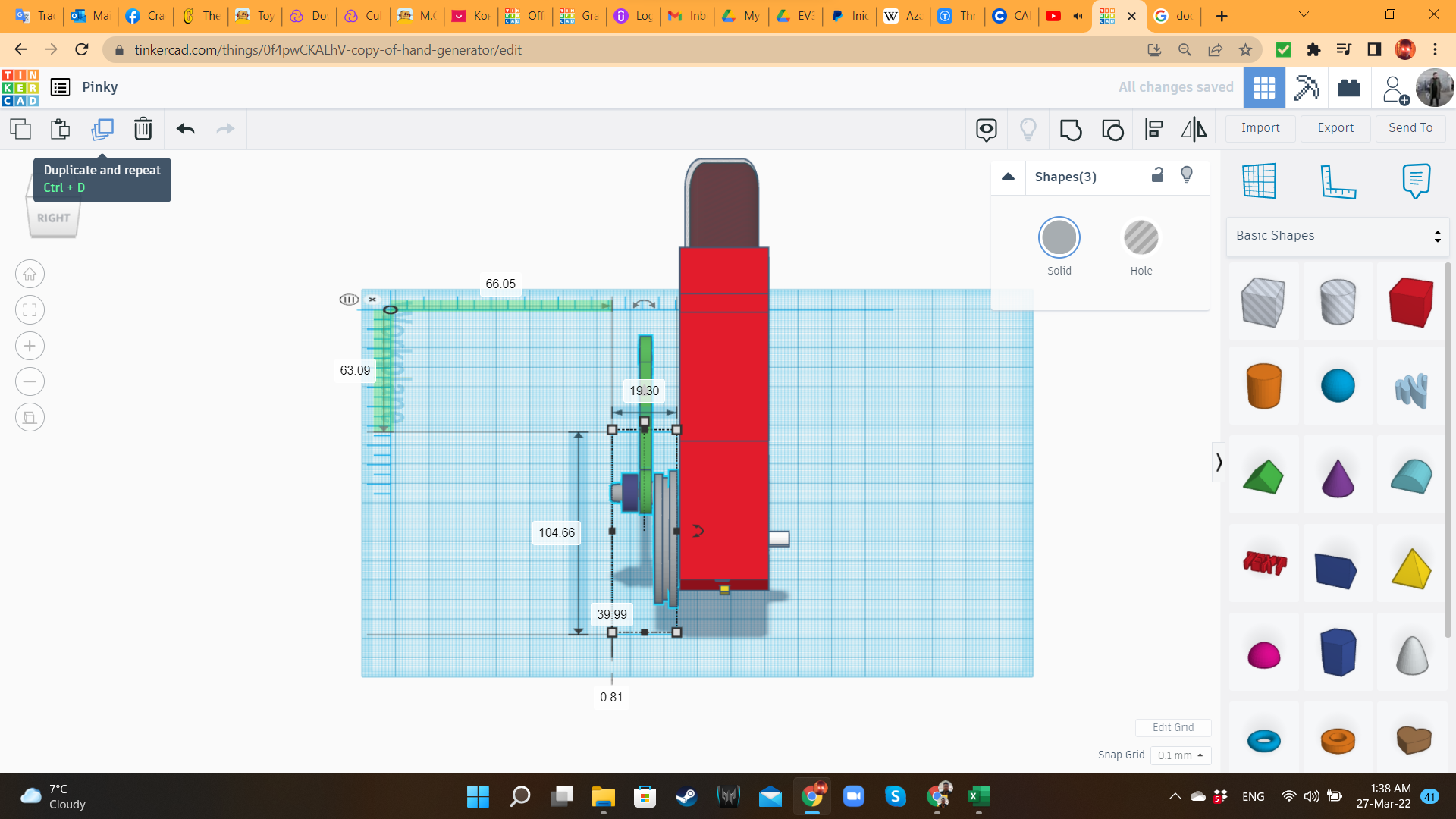
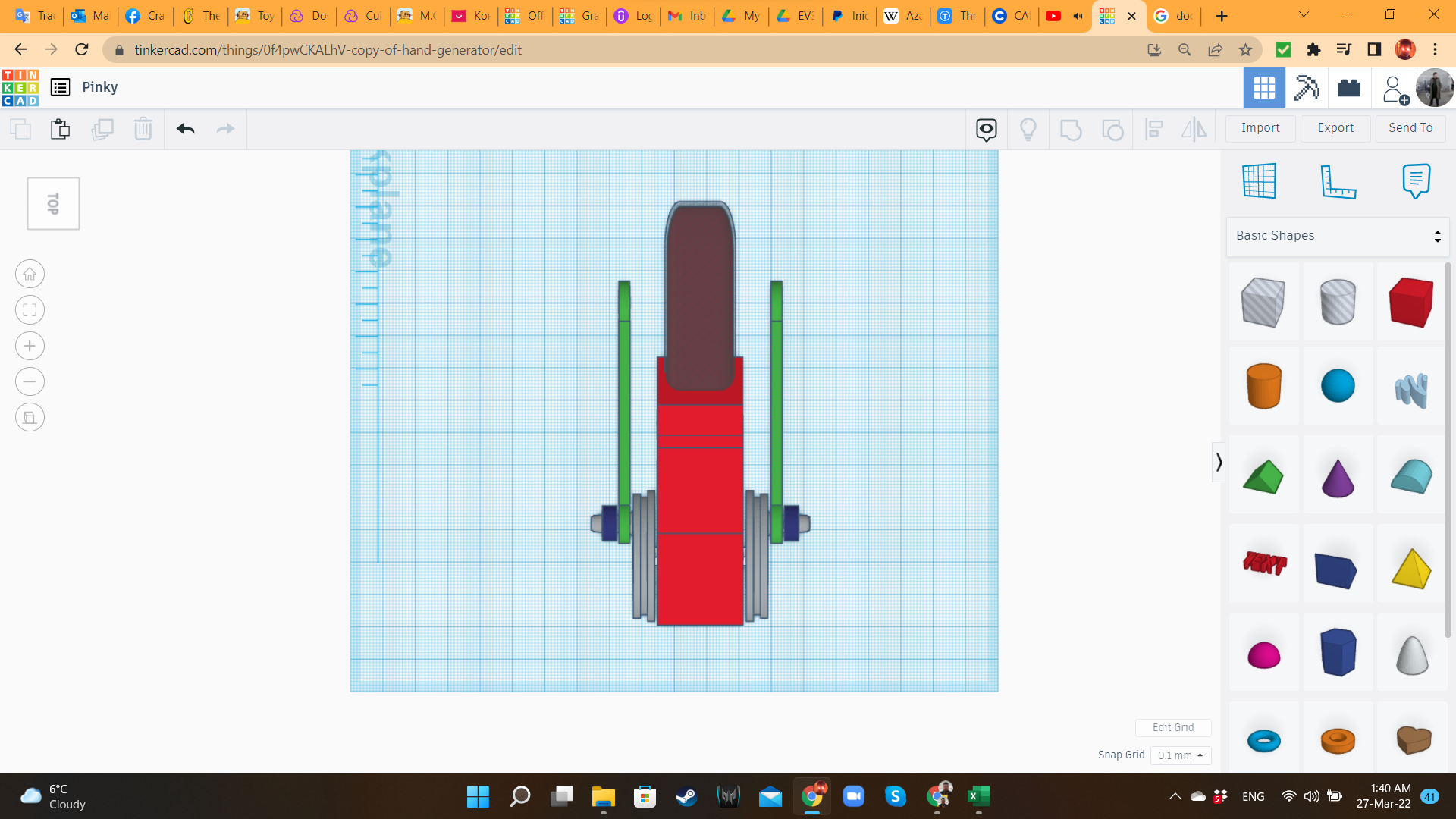
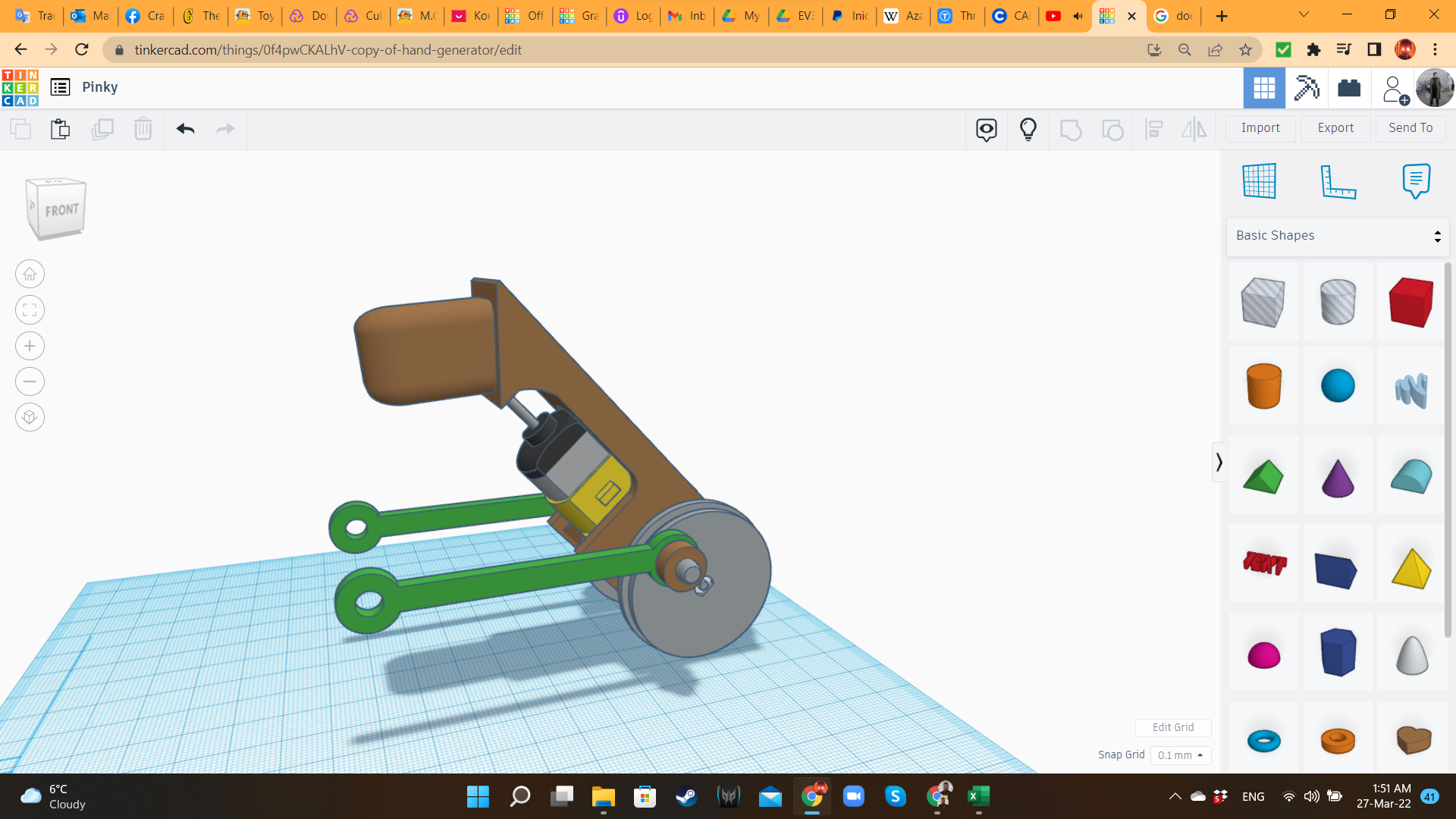
Using the Duplicate and Mirror Tools, I created a symmetric duplicate, and placed it on the other side of the motor.
Pinky 5: Base Body
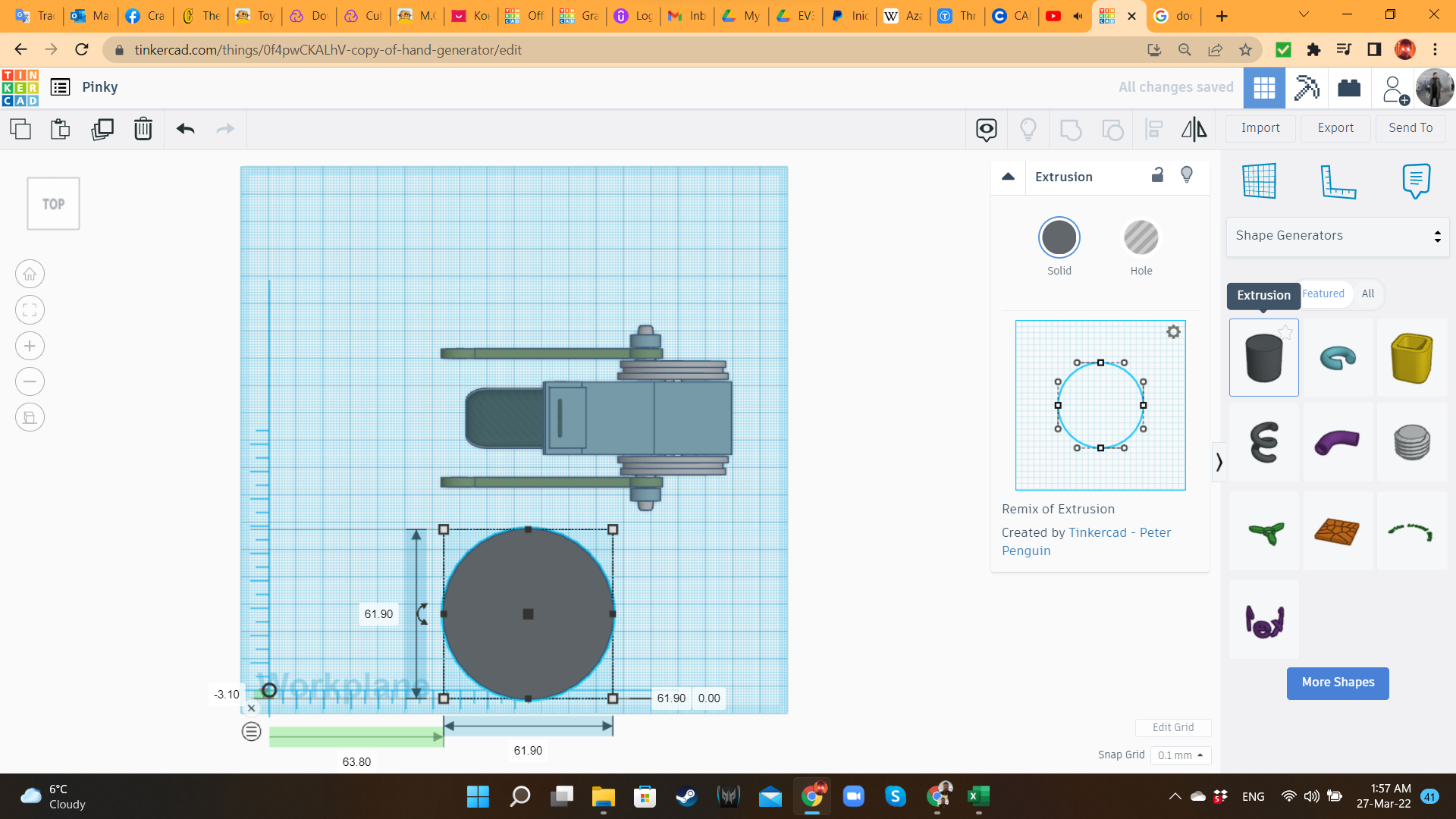
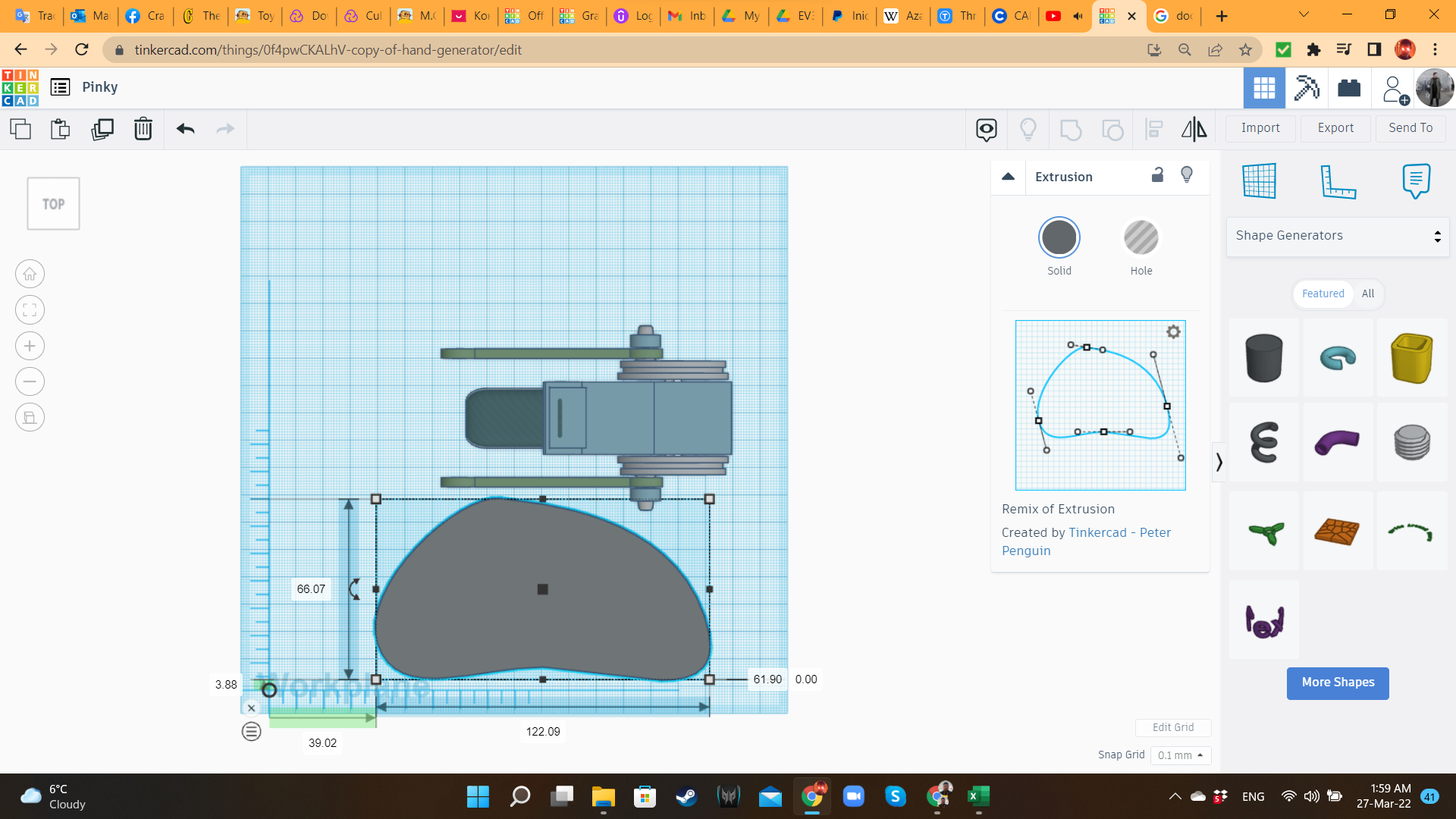
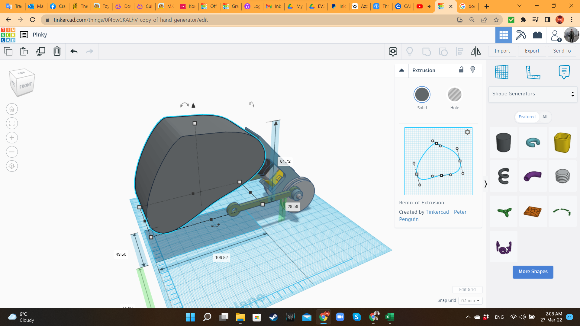
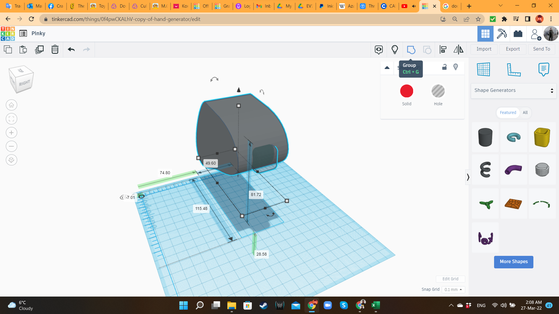
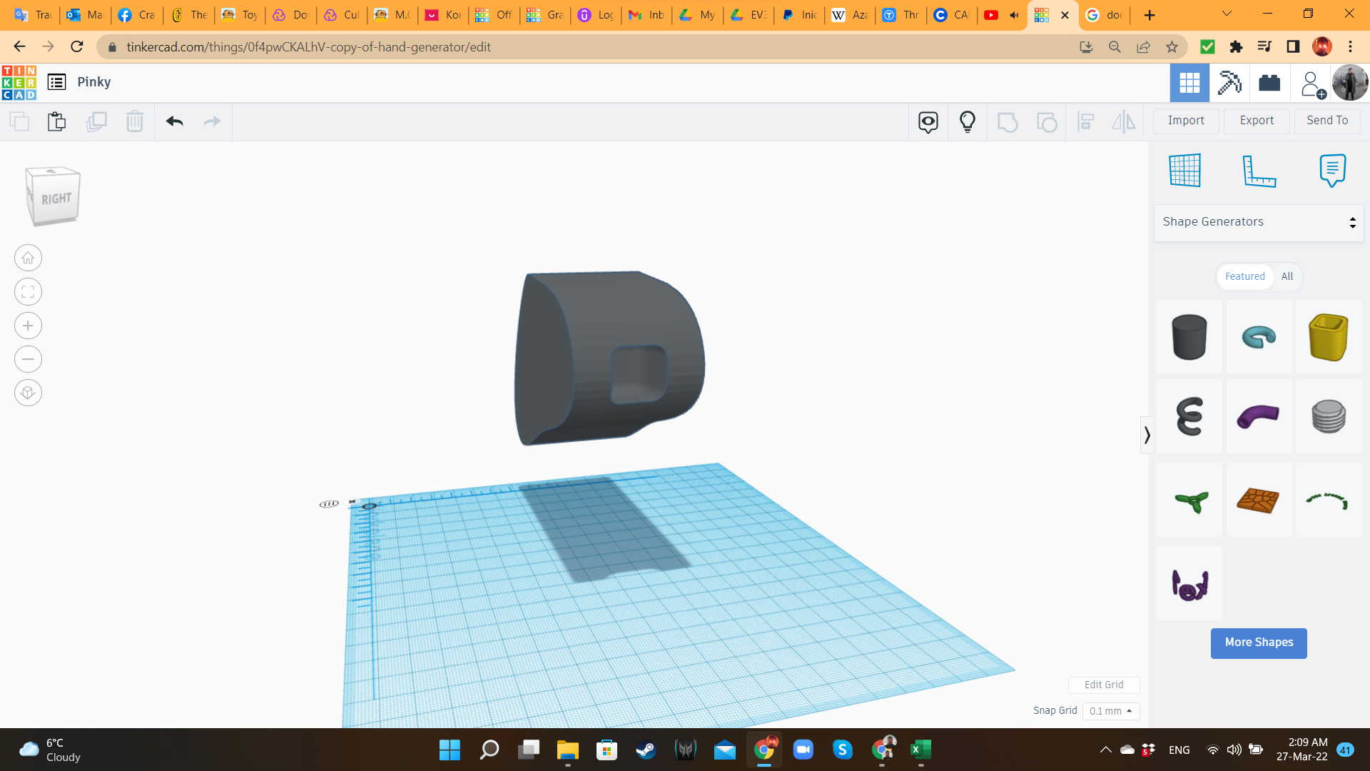
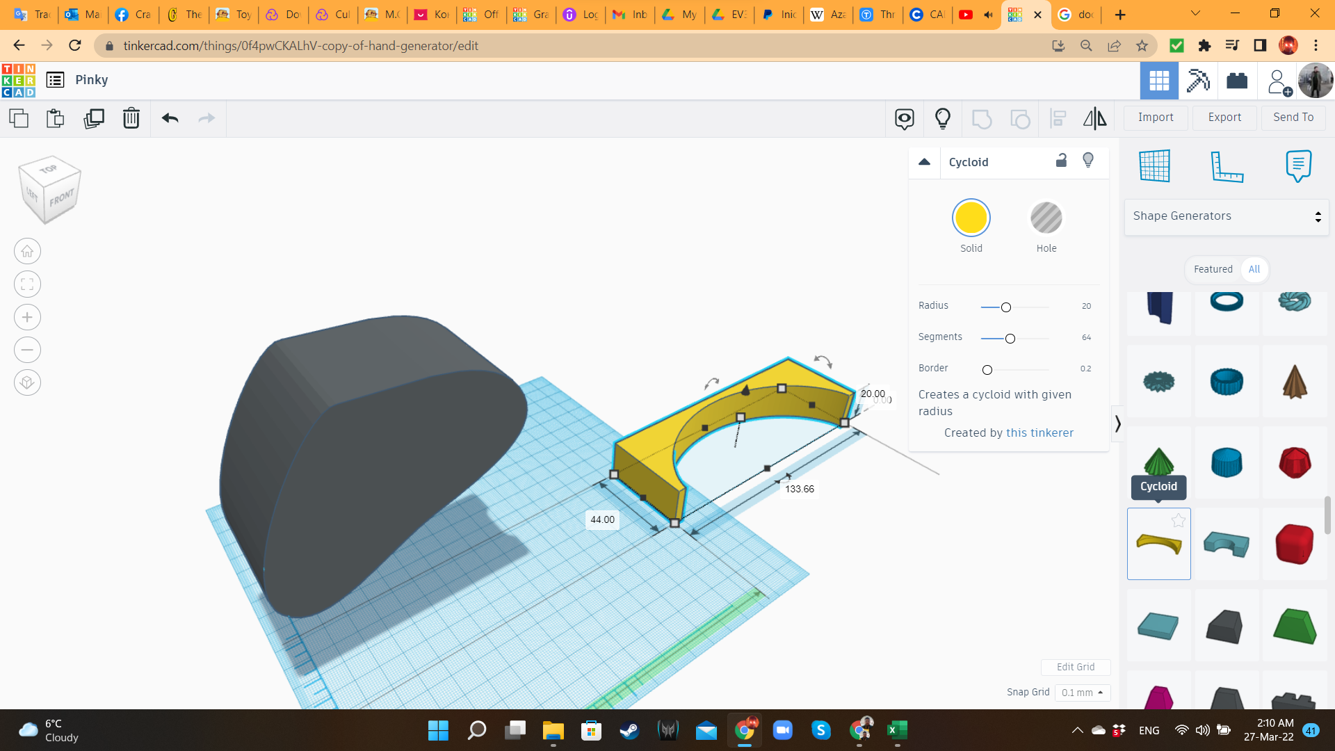
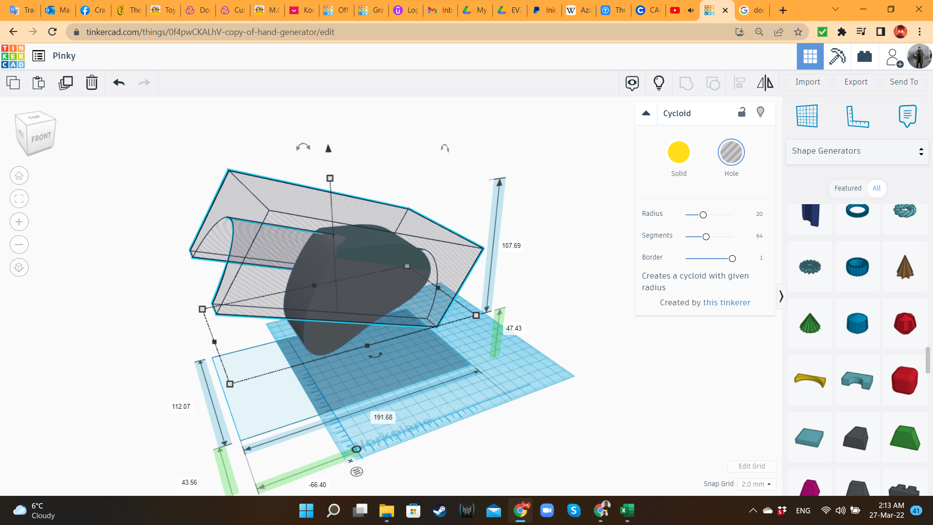
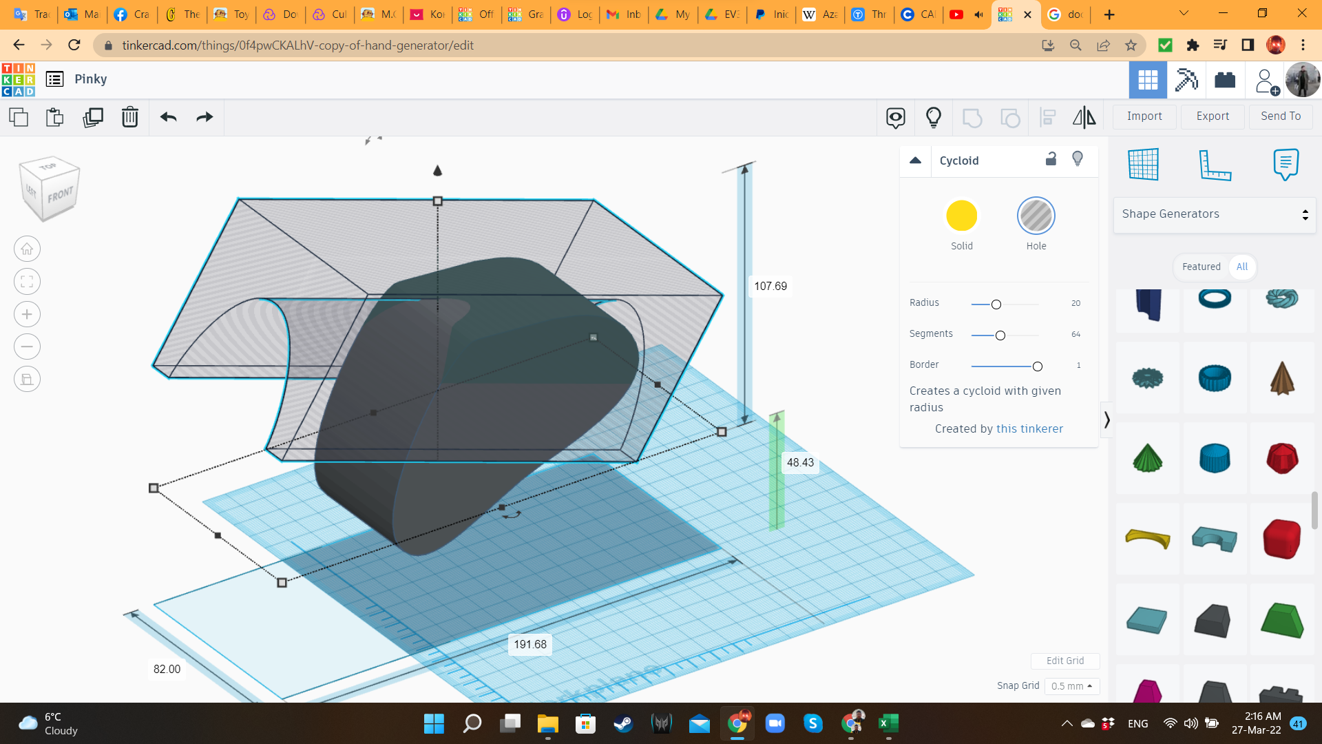
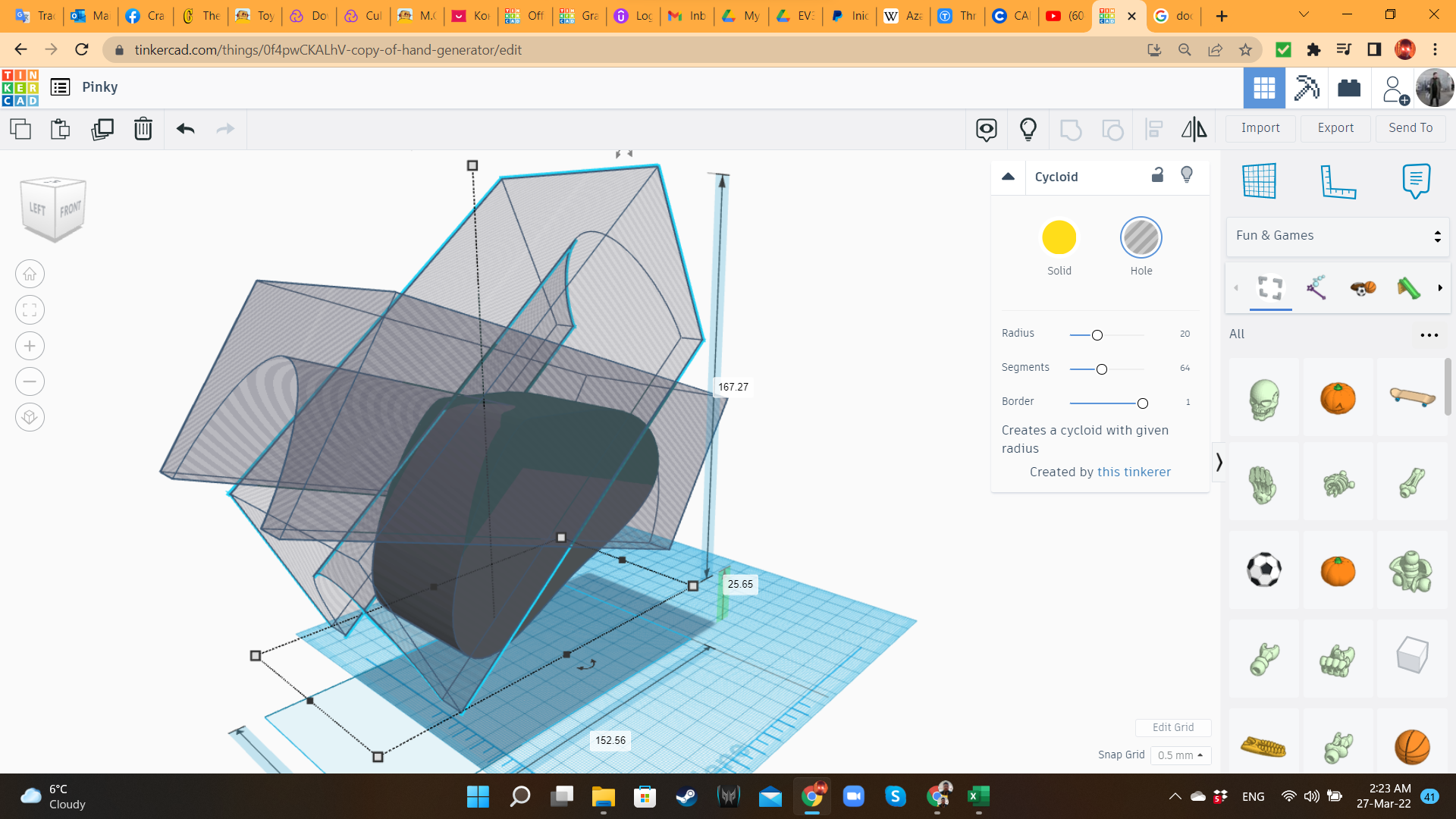
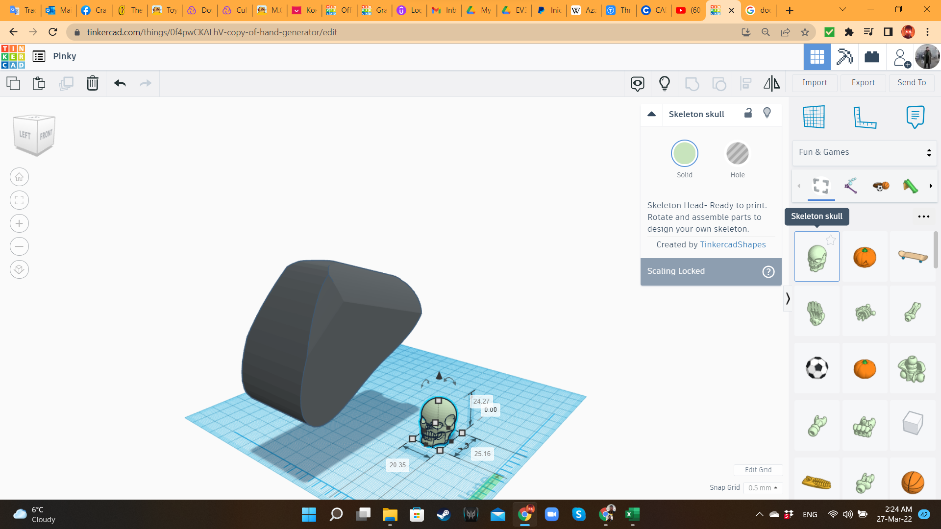
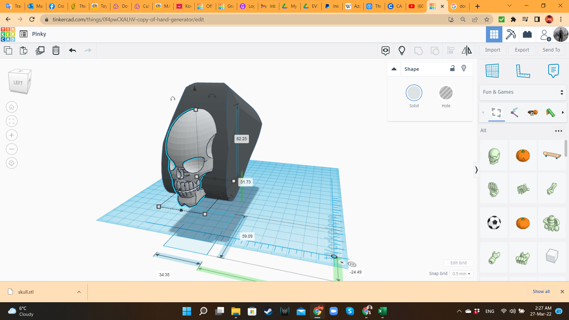
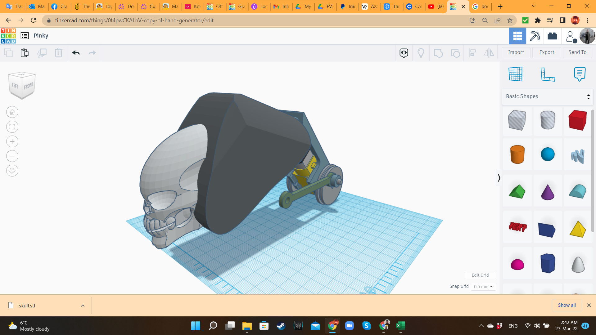
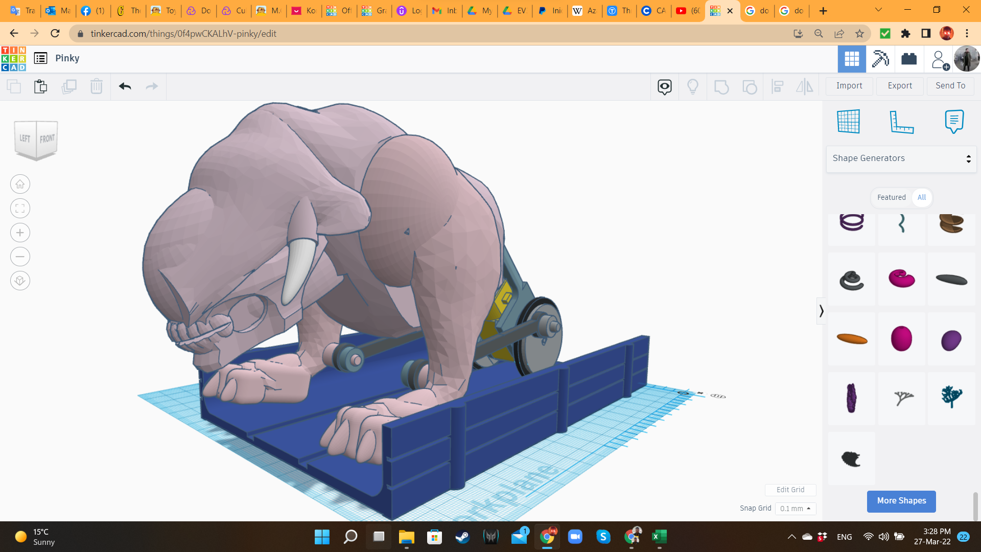
Let's start creating the "organic" body of our Battle Beast! I brought a Extrusion and some MetaFillets from "Shape Generators", and a Skeleton Skull from "Fun & Games / Building Toys". I started giving them shape, with the idea of transforming these shapes into some scary monster. And... and... and...
And nothing. The reality is that I'm not good designing organic shapes. That's my weak point. So far, this monster was just a human skull in a grey block, with funny wheels in the back. Besides, I didn't have any idea about what kind of legs I could use with this thing. I needed a solution, and I needed it fast!
Pinky 6: Creating a Chimera
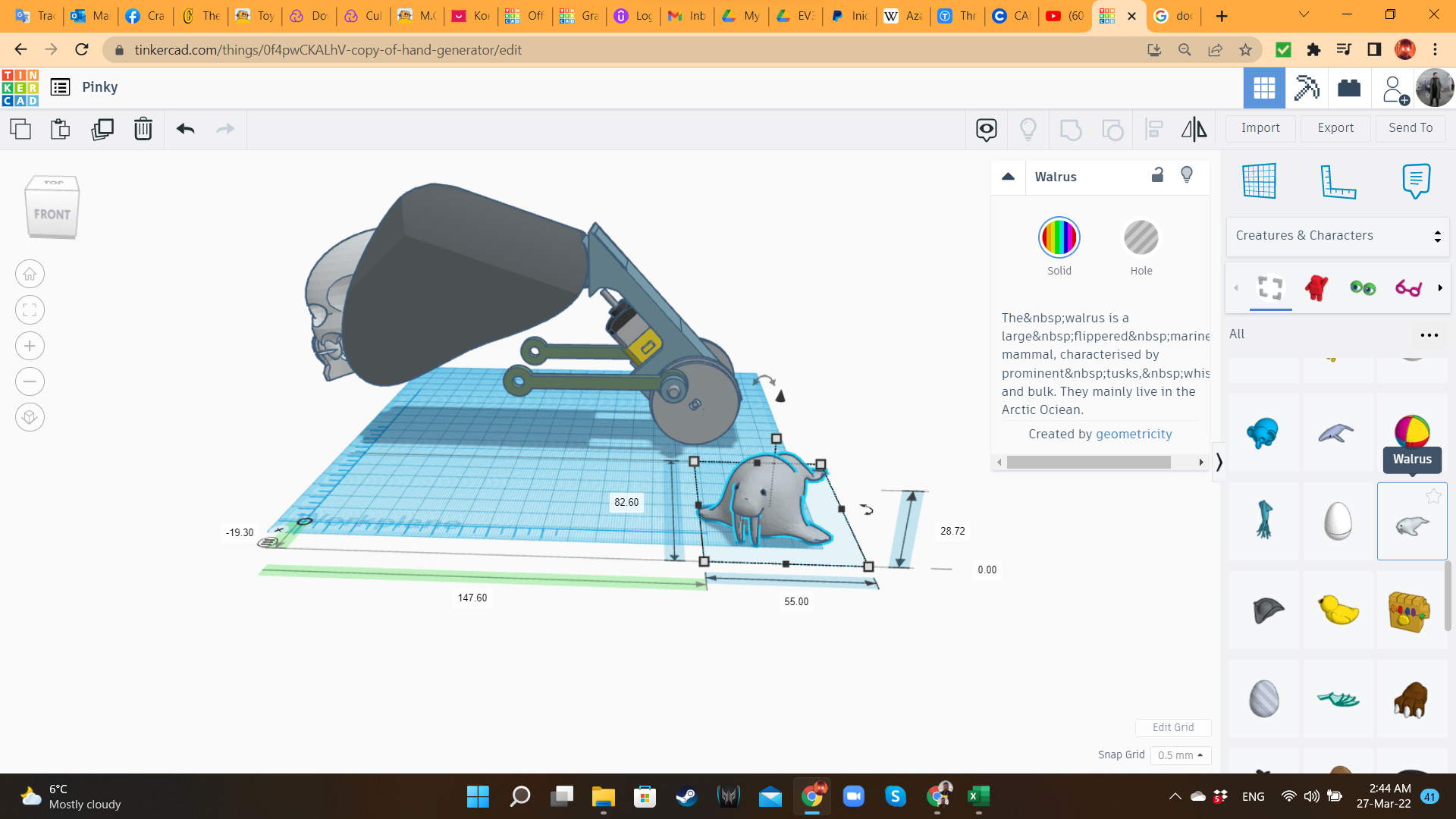
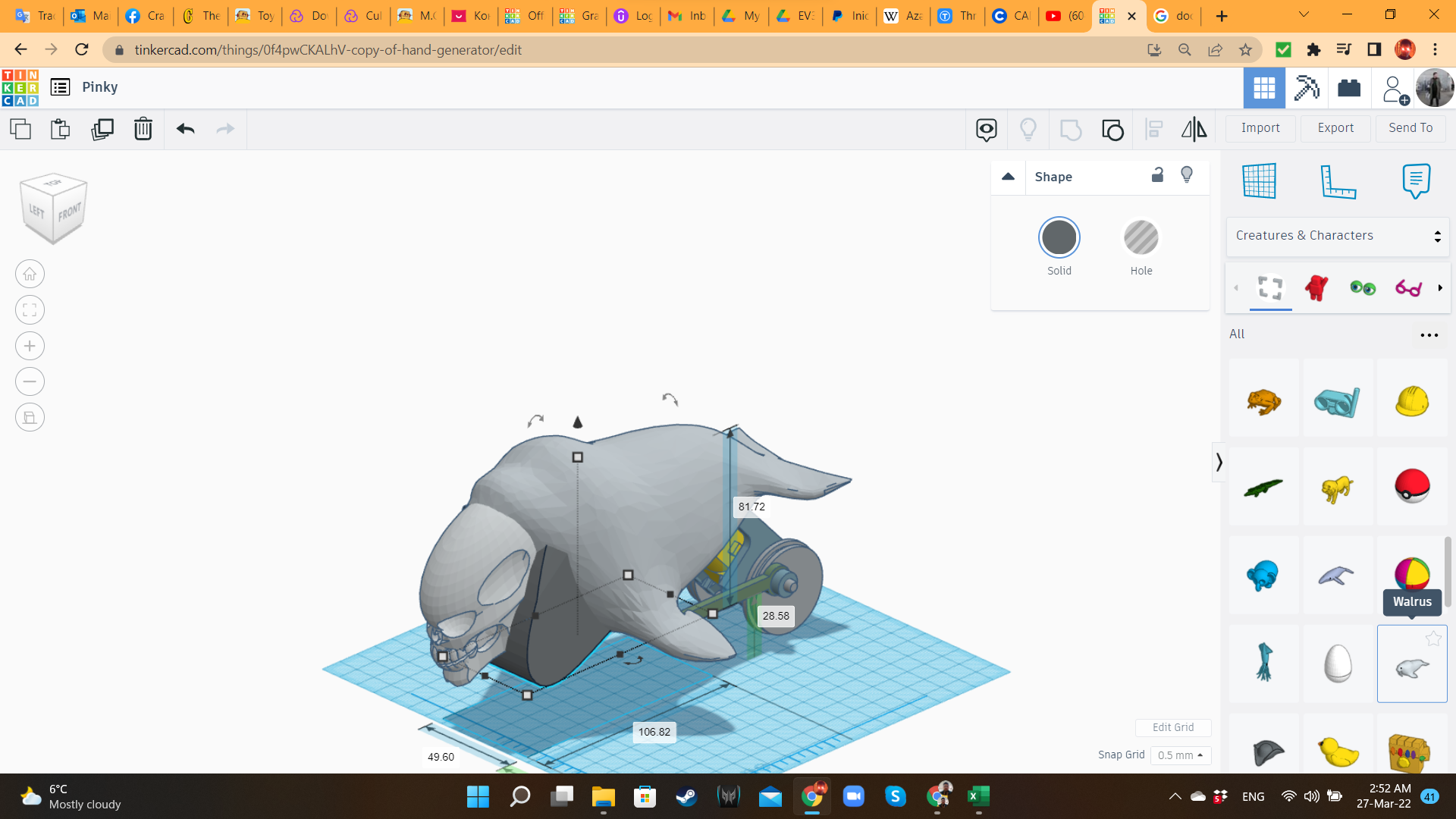
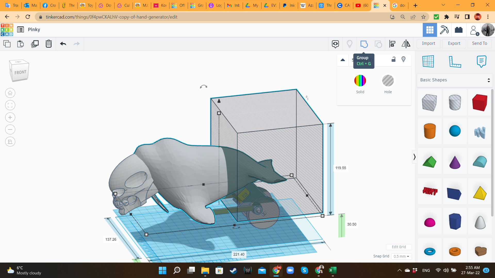
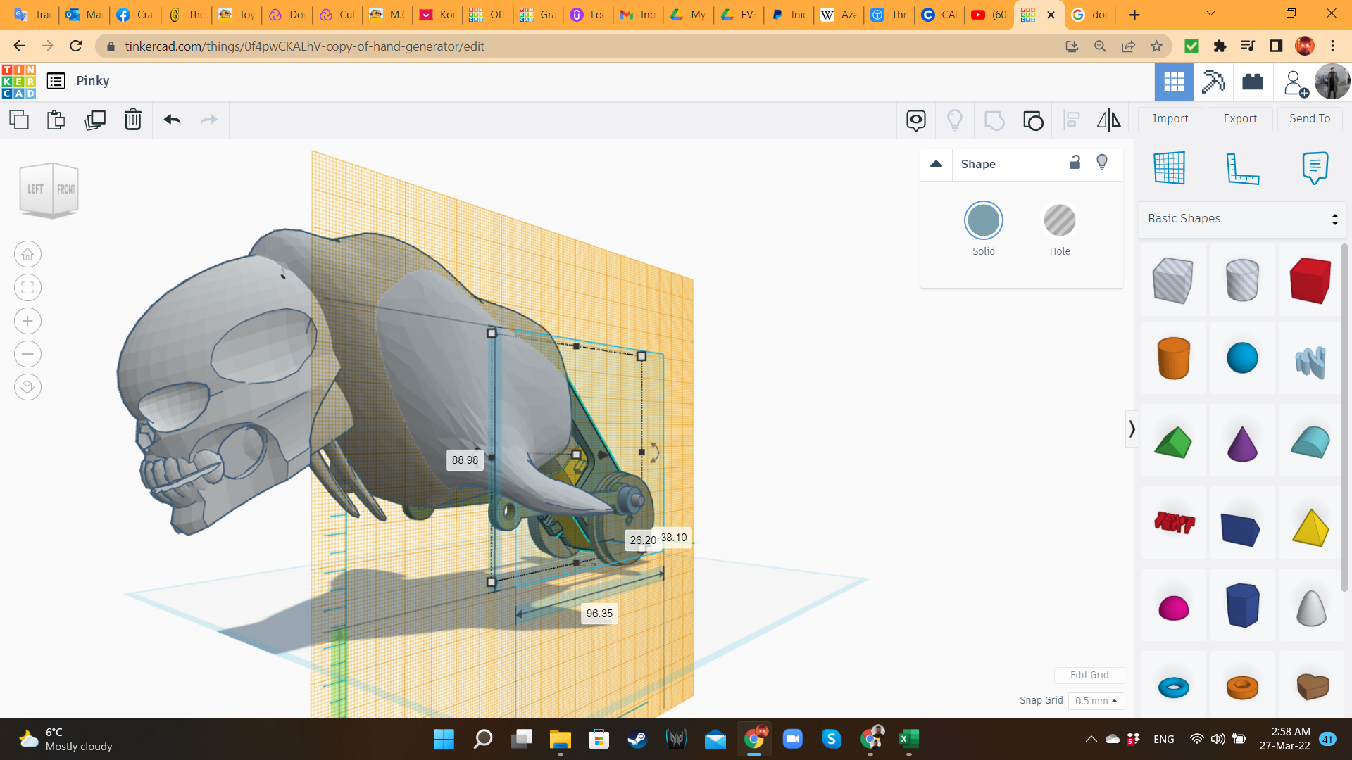
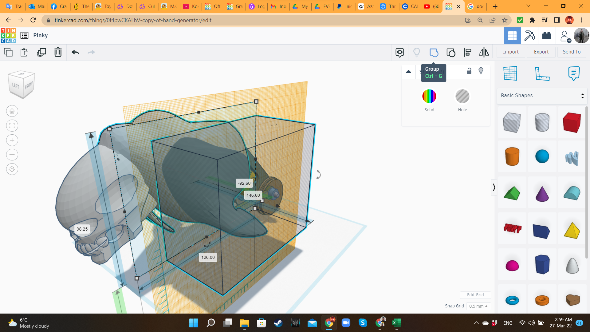
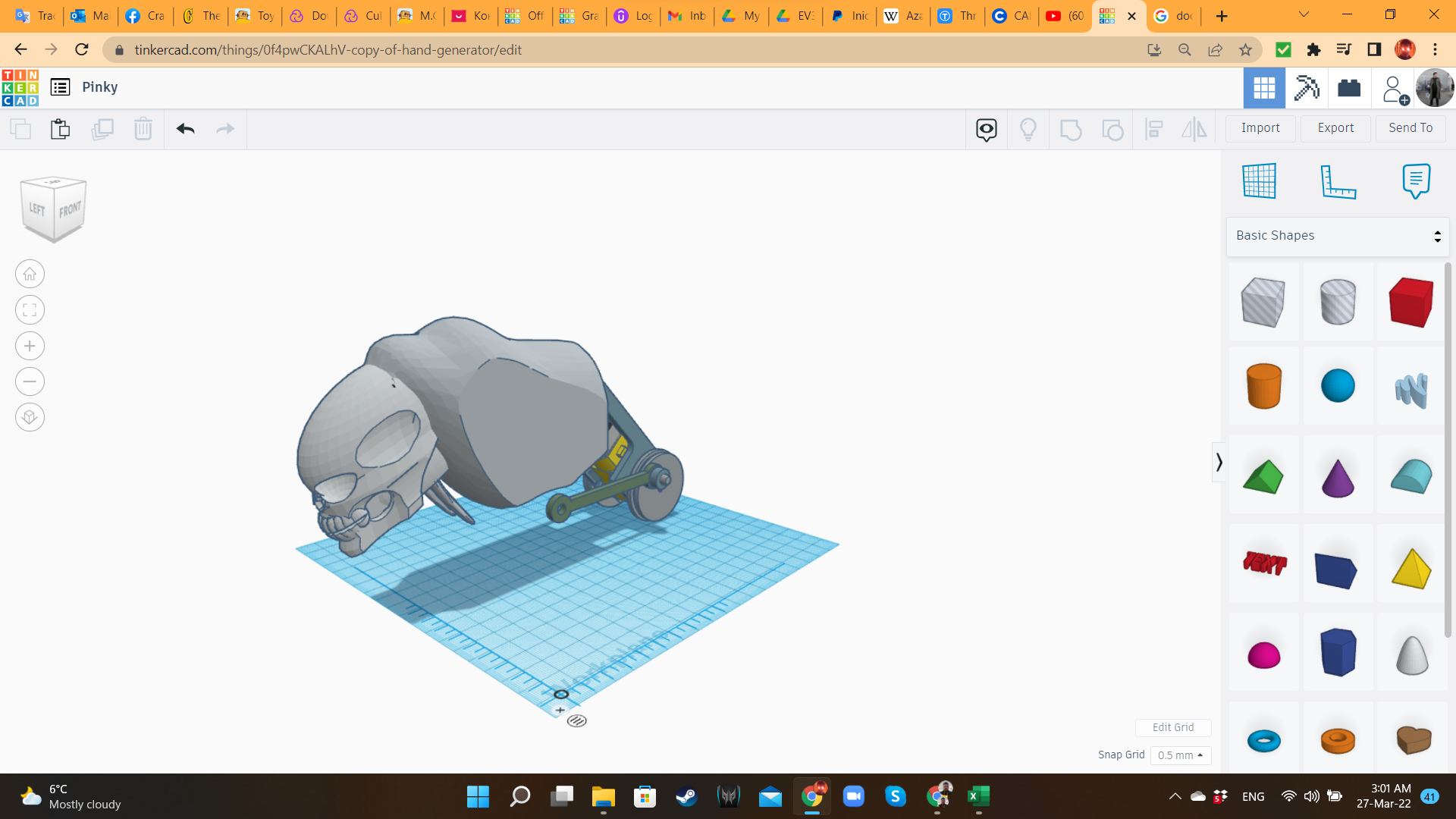
Then, I remembered that Tinkercad has animals in its library. What if I could bring those animals to the workplane, deform their dimensions, and try to build something with their parts?
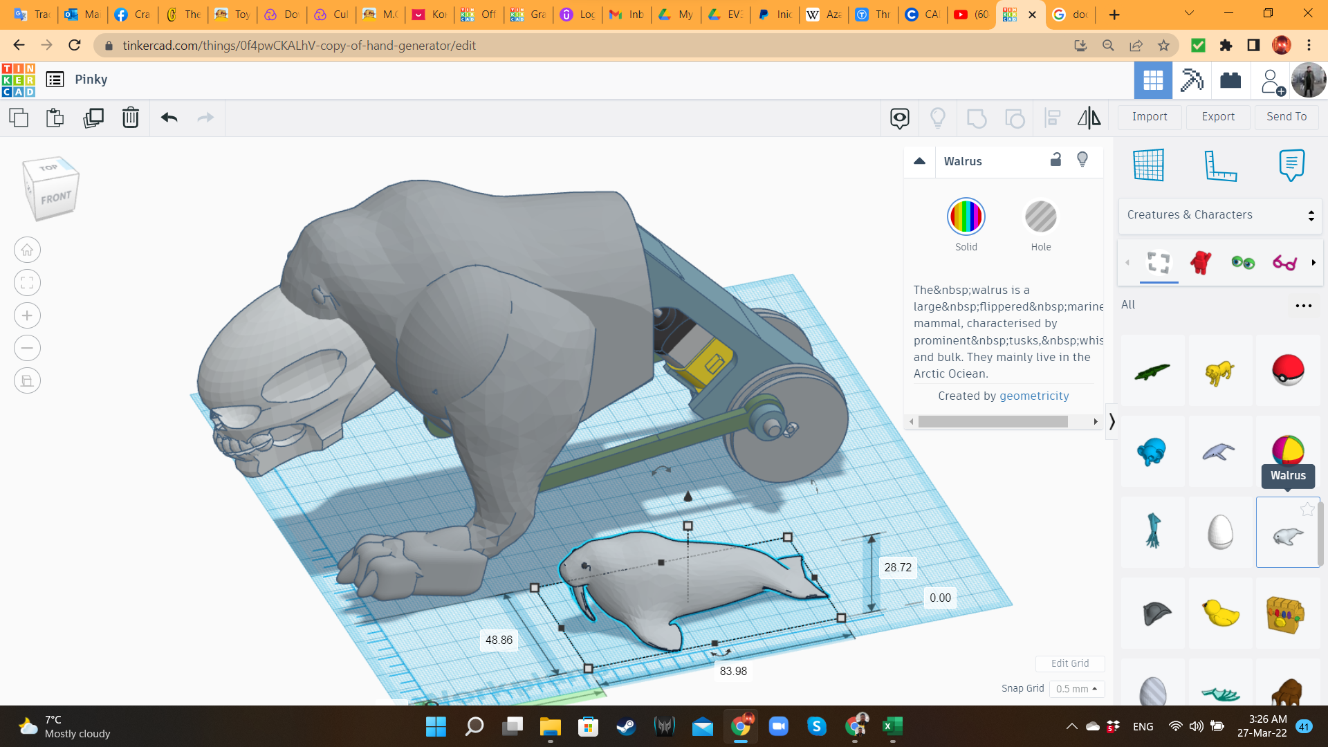
The first "test subject" from my Frankenstein experiment was the cute Walrus from the "Creatures and Characters" library. The body was perfect to create Pinky's main body. I cut the tail and flippers using hole Boxes. I also removed the Extrusion shape from the previous step. It was not useful anymore.
Pinky 7: Legs
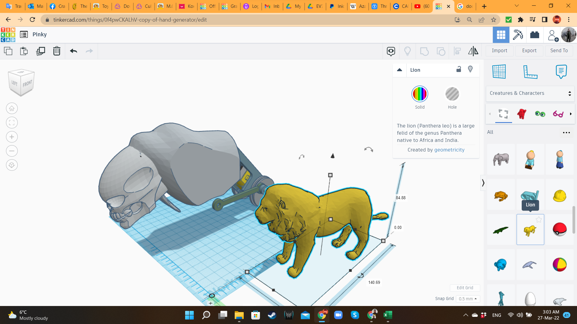
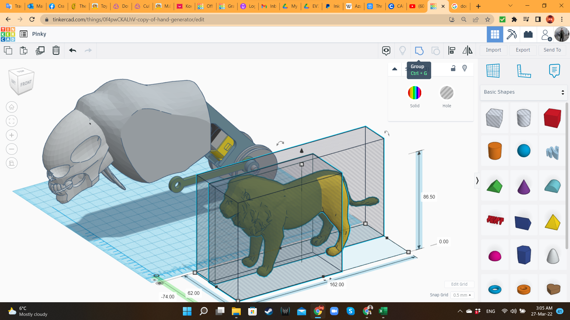
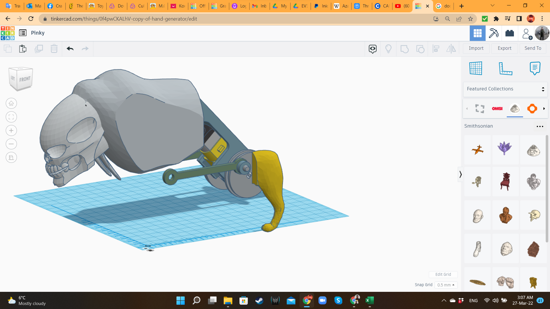
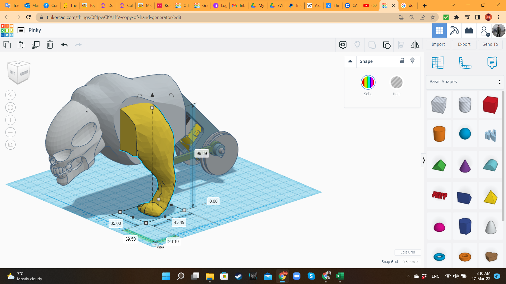
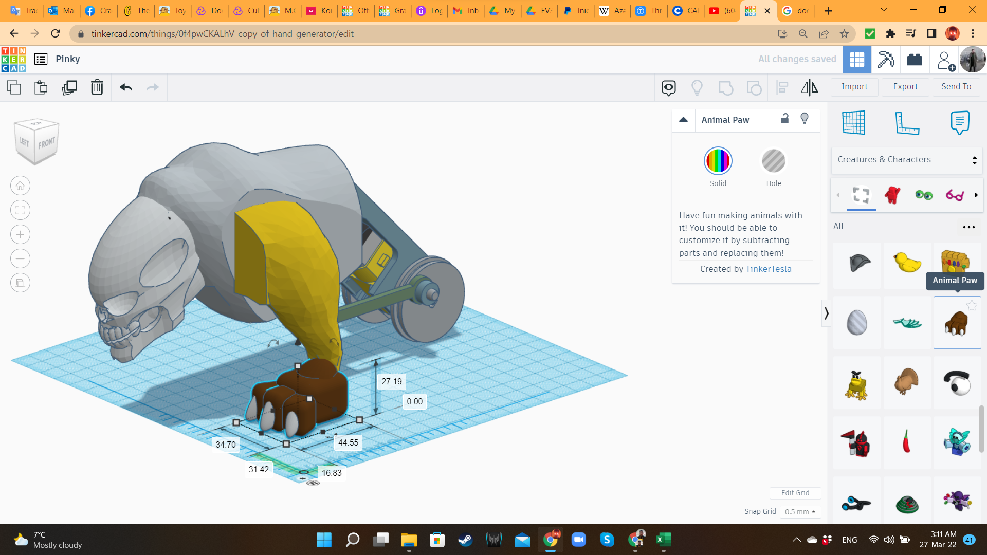
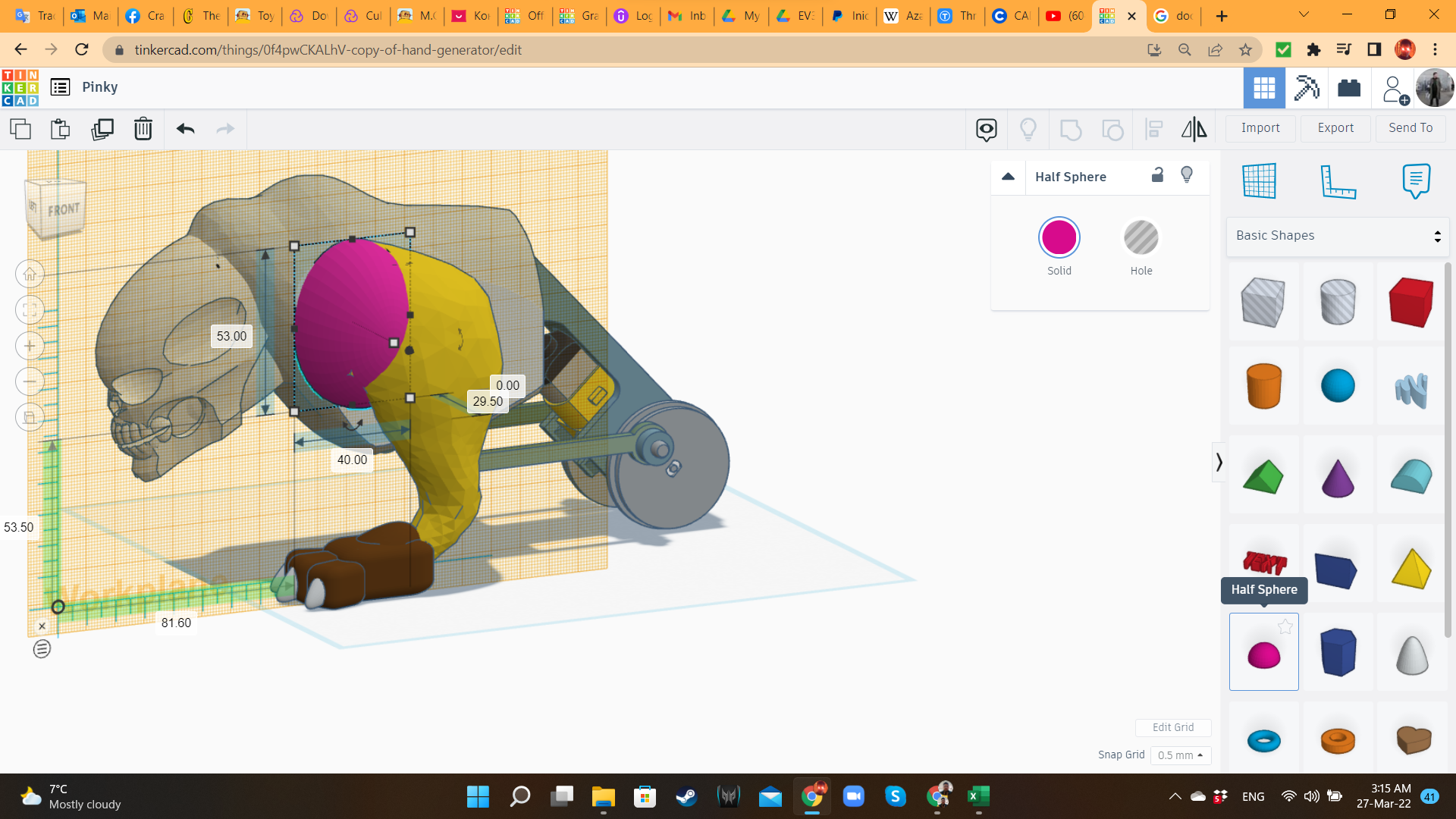
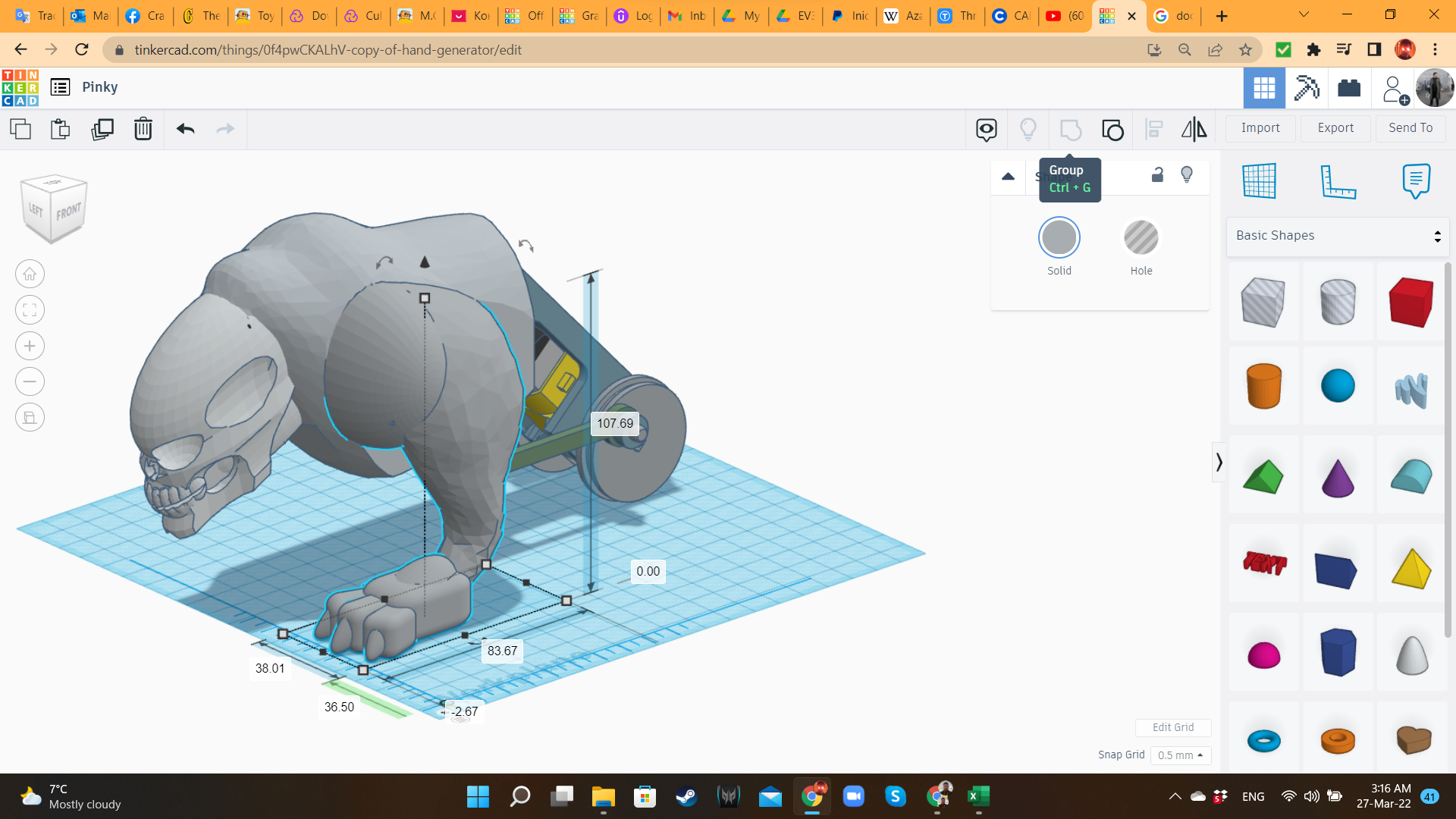
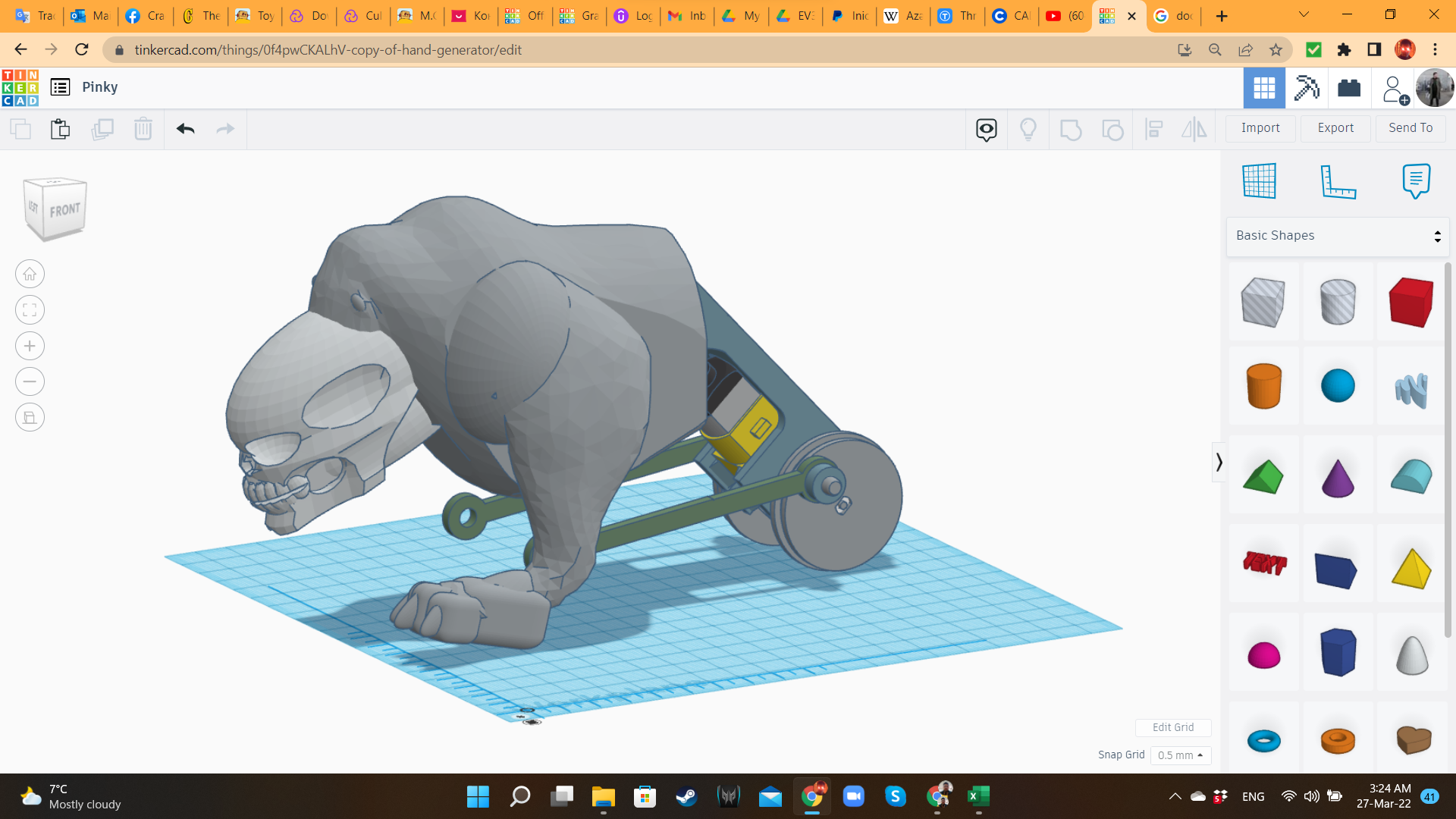
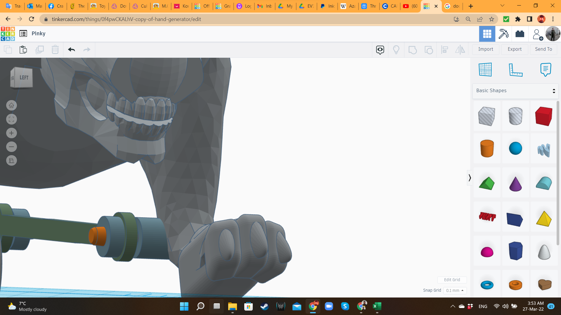
For the leg, I brought the Lion, and cut everything but one of the rear legs. I scaled it, adding an Animal Paw from the same library. Then, I inserted a cylinder with the same dimensions of the wheel/crank.
Pinky 8: the Head of the Beast
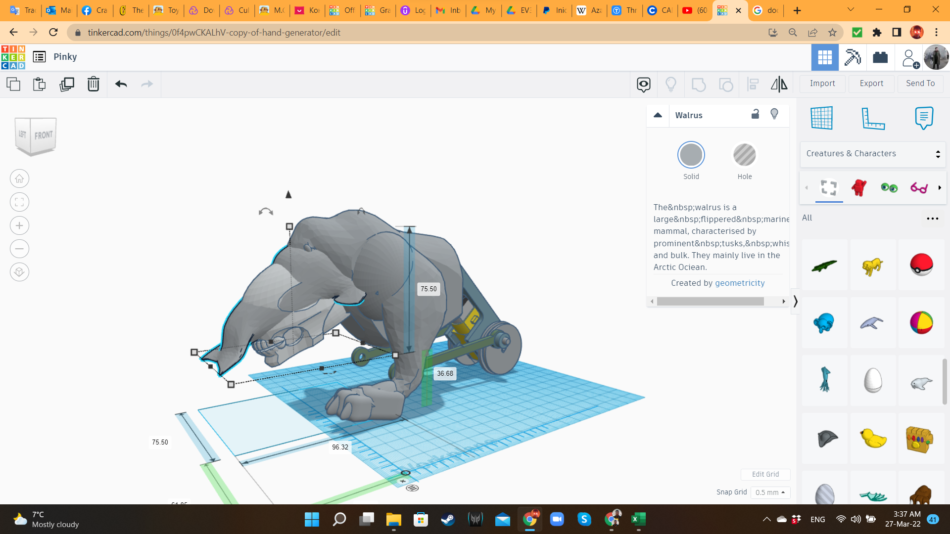
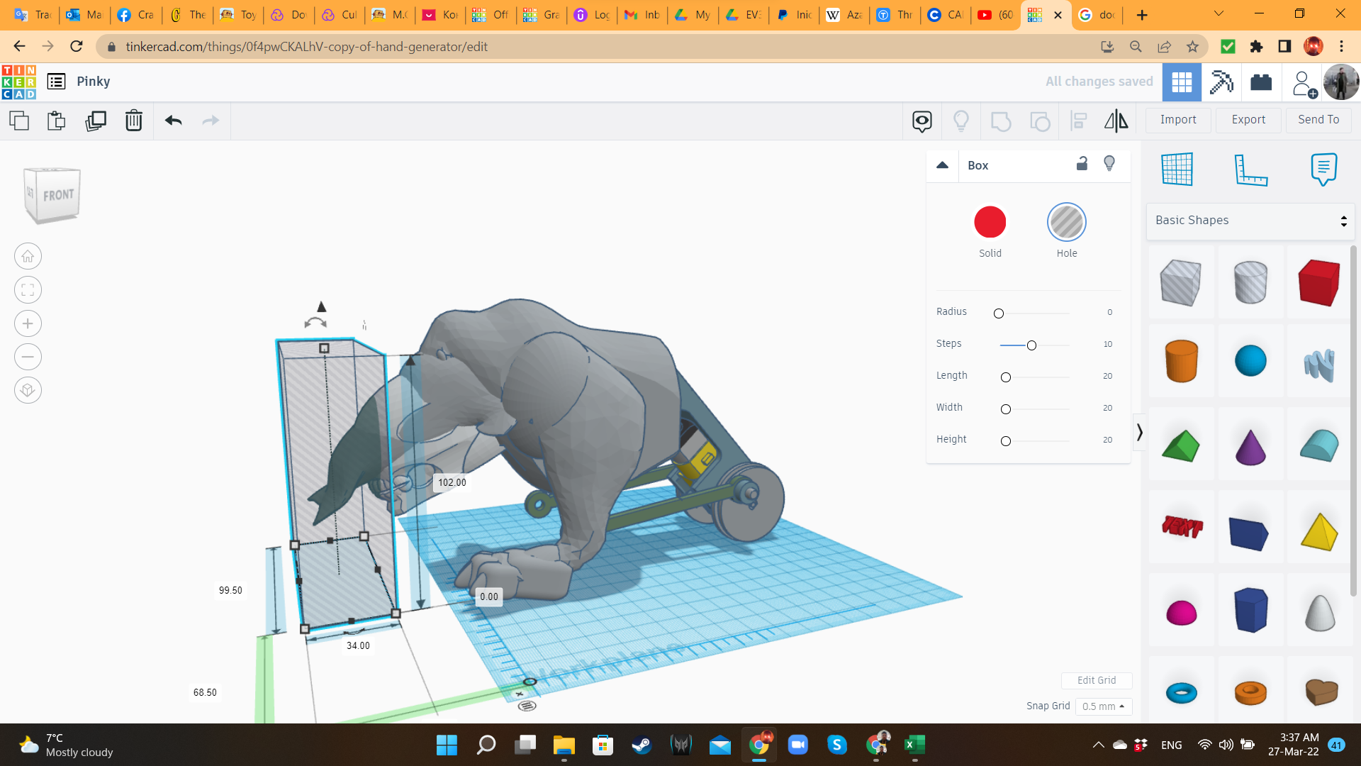
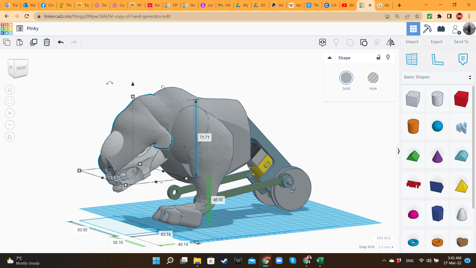
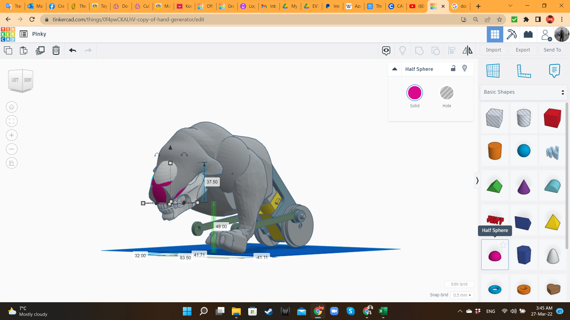
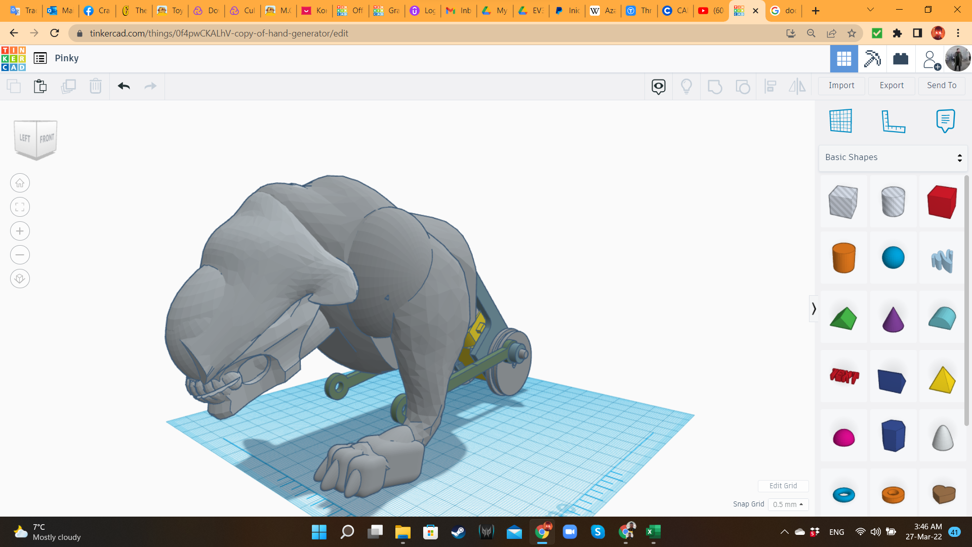
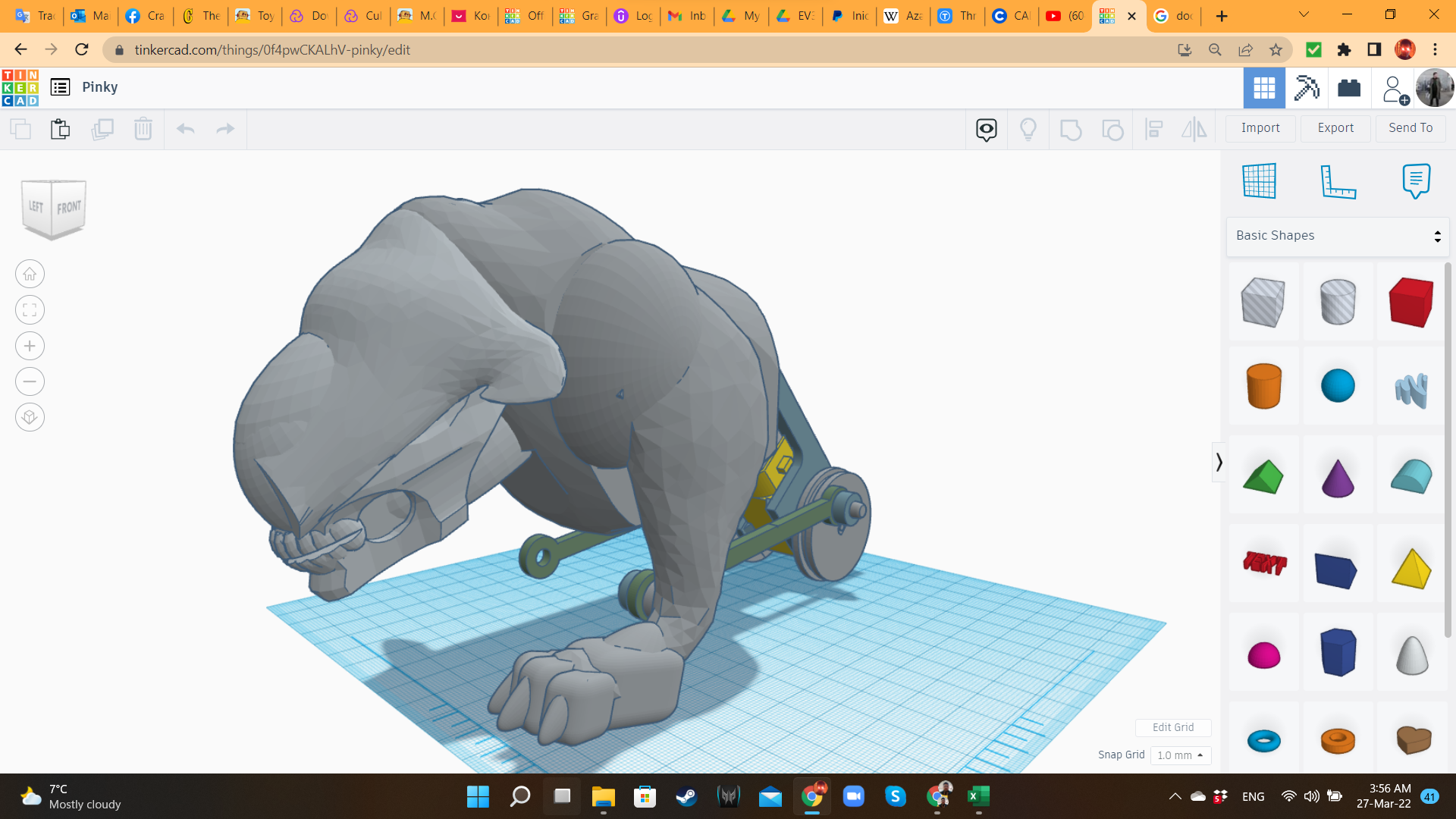
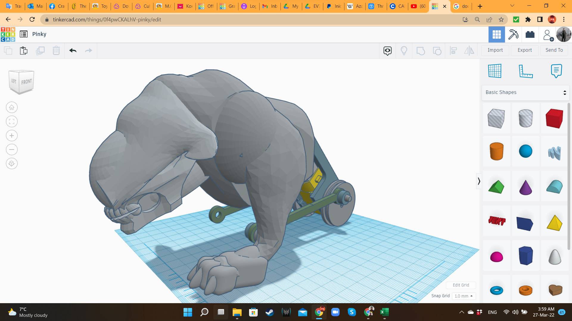
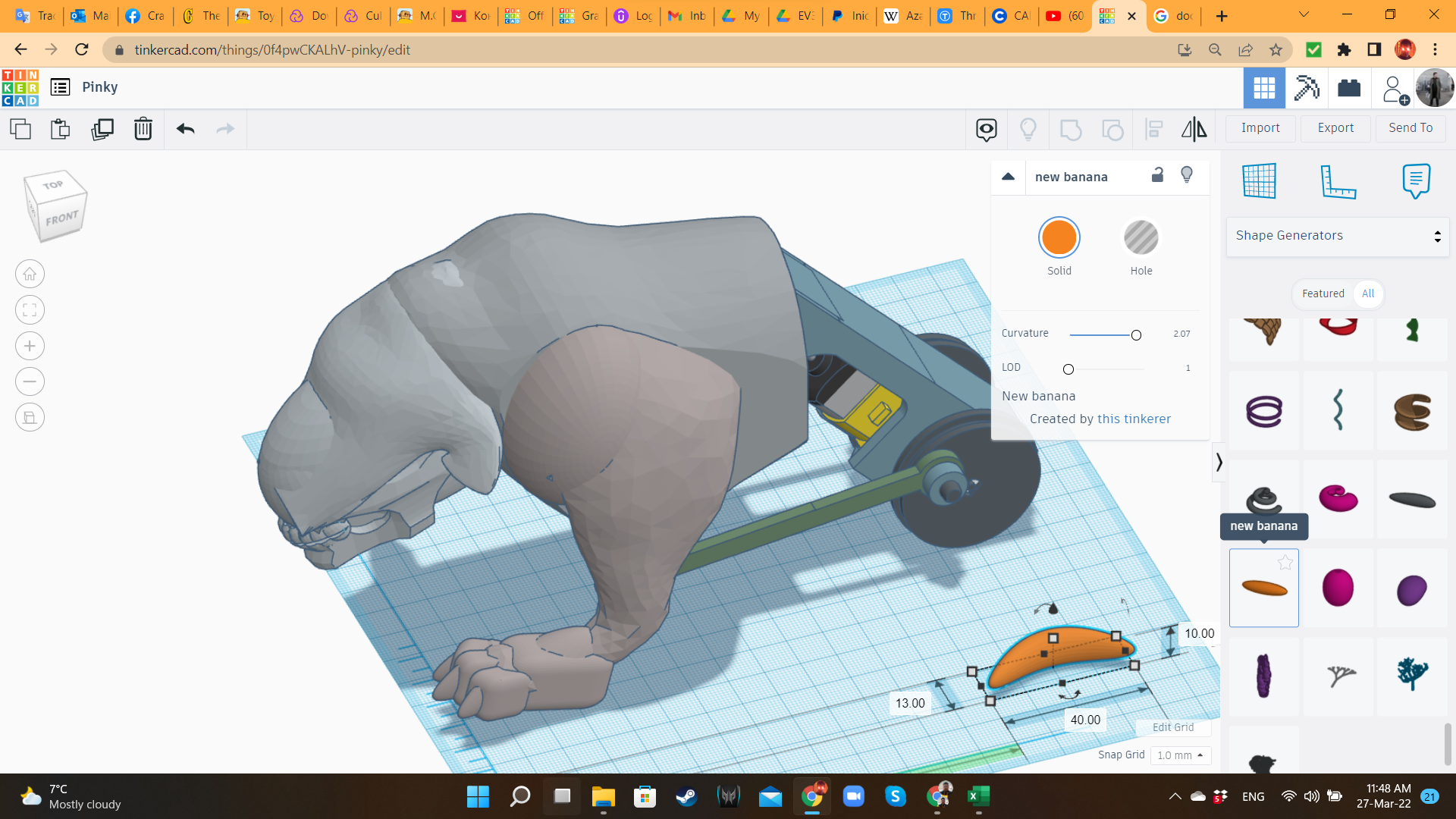
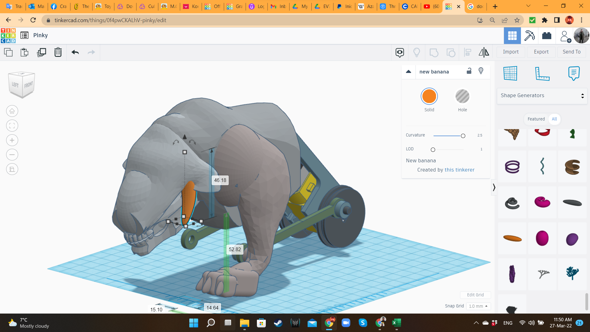
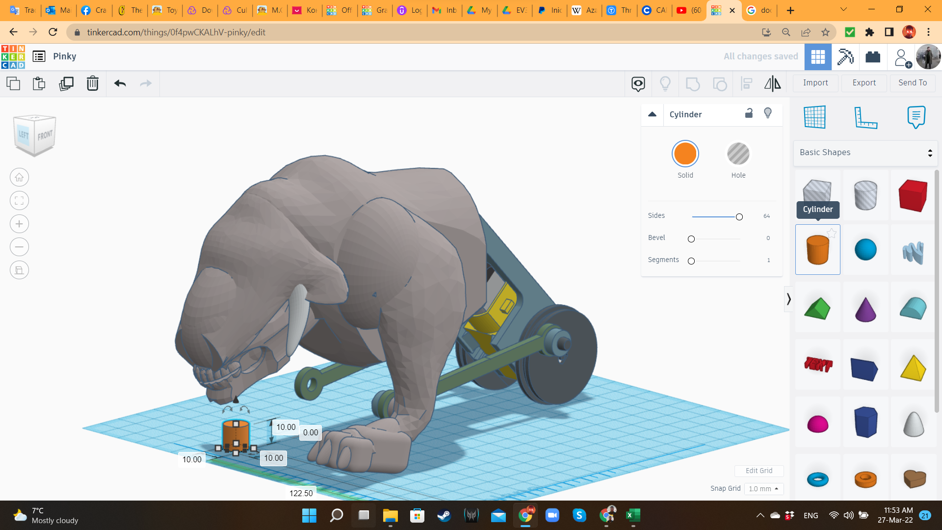
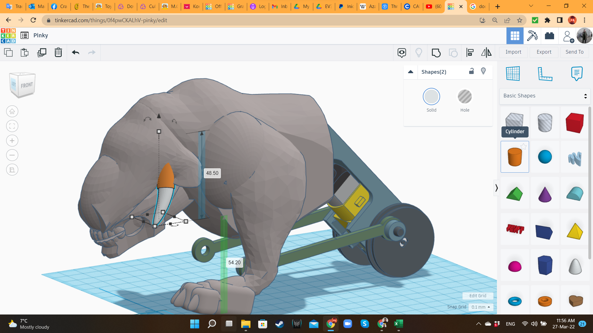
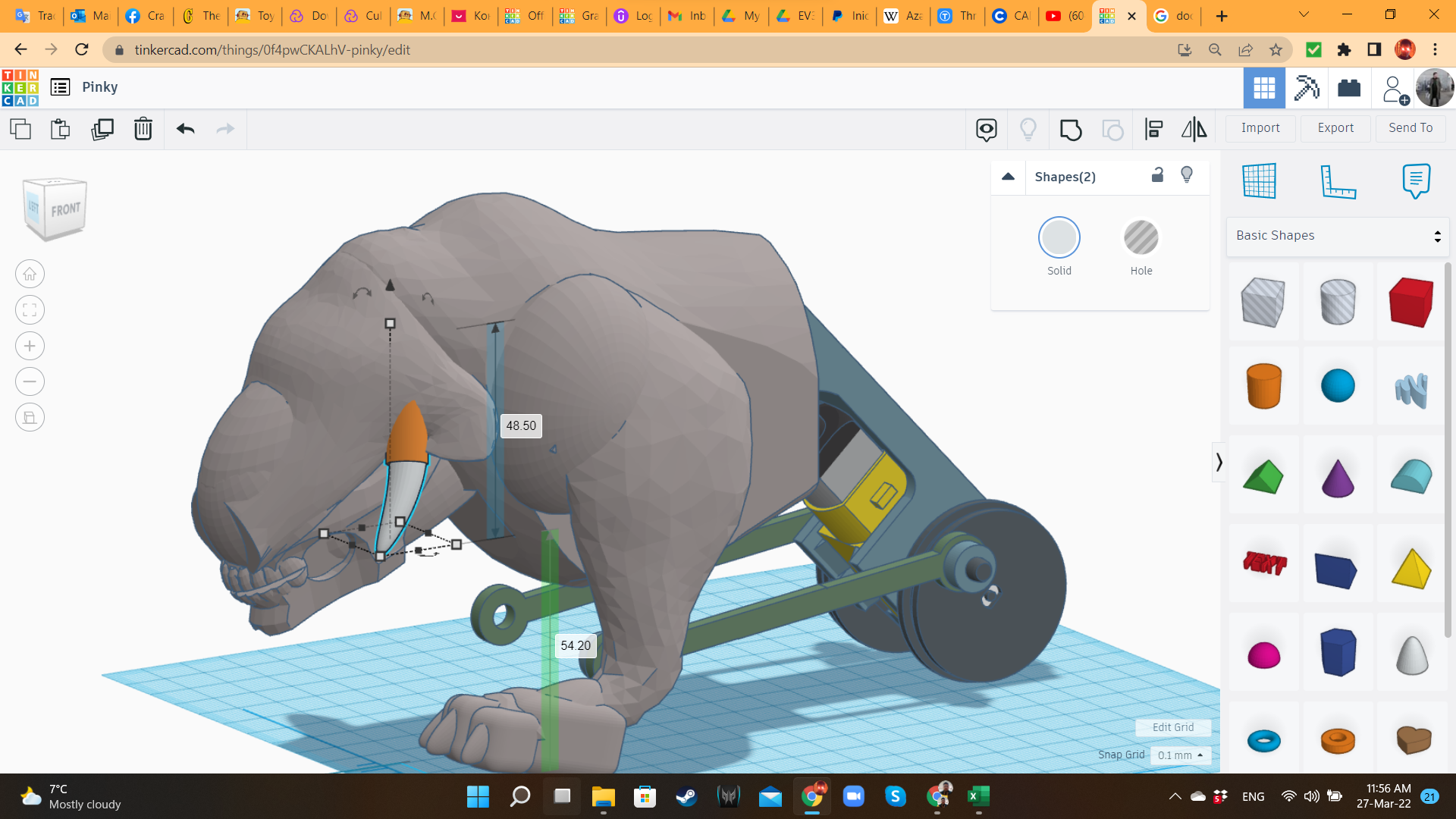
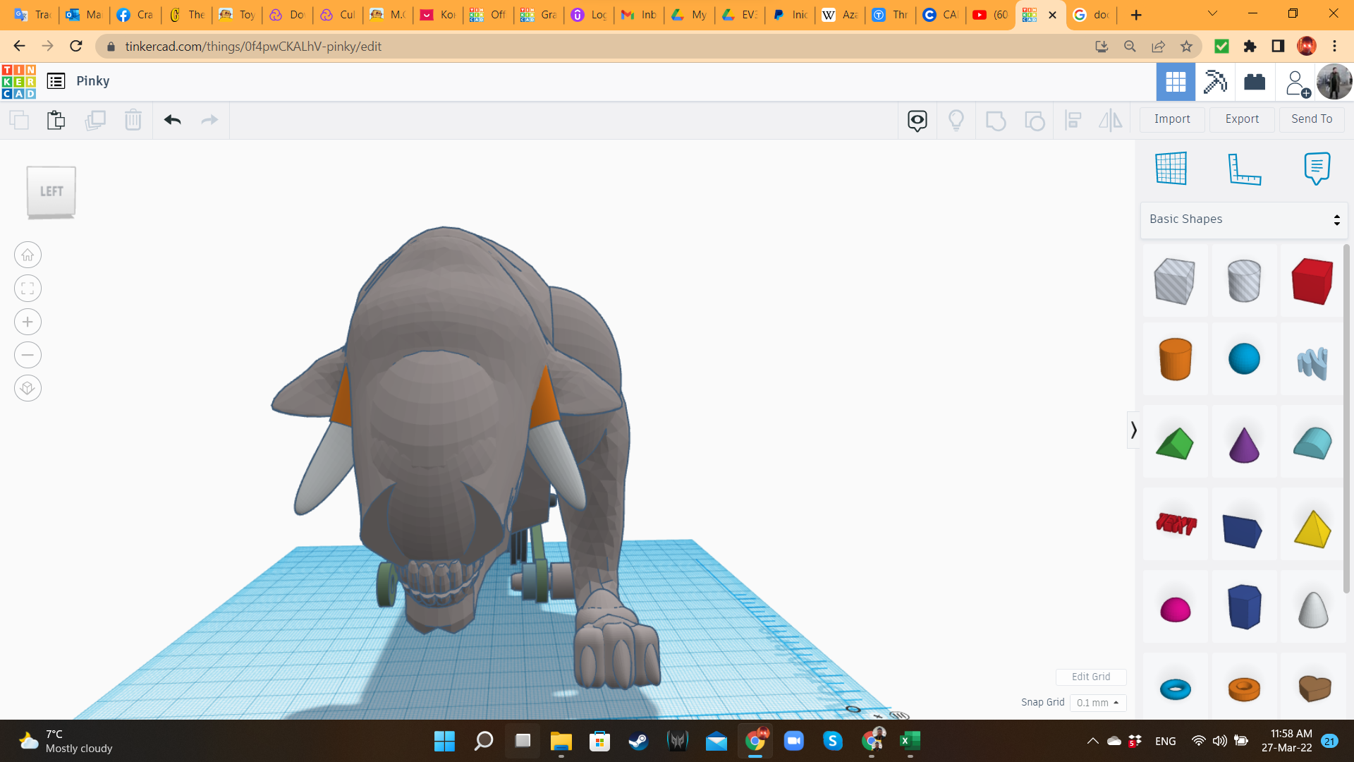
For the head, I brought a third Walrus and inverted it. Then I cut the tail. I left the flippers, because they would work perfectly as ears. Using a half sphere and the Skull, I gave shape to the head. At the end, I added a New Banana from "Shape Generators", to create the tusk/horn.
Pinky 9: Leg Joint
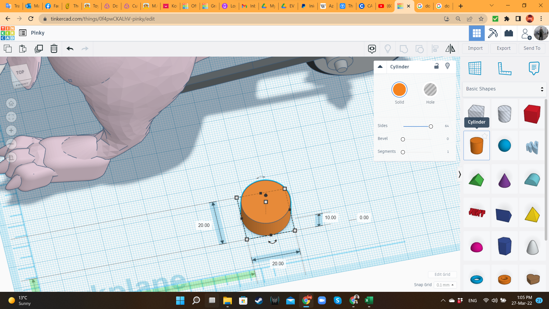
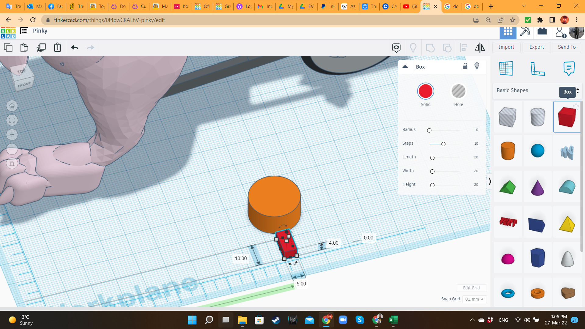
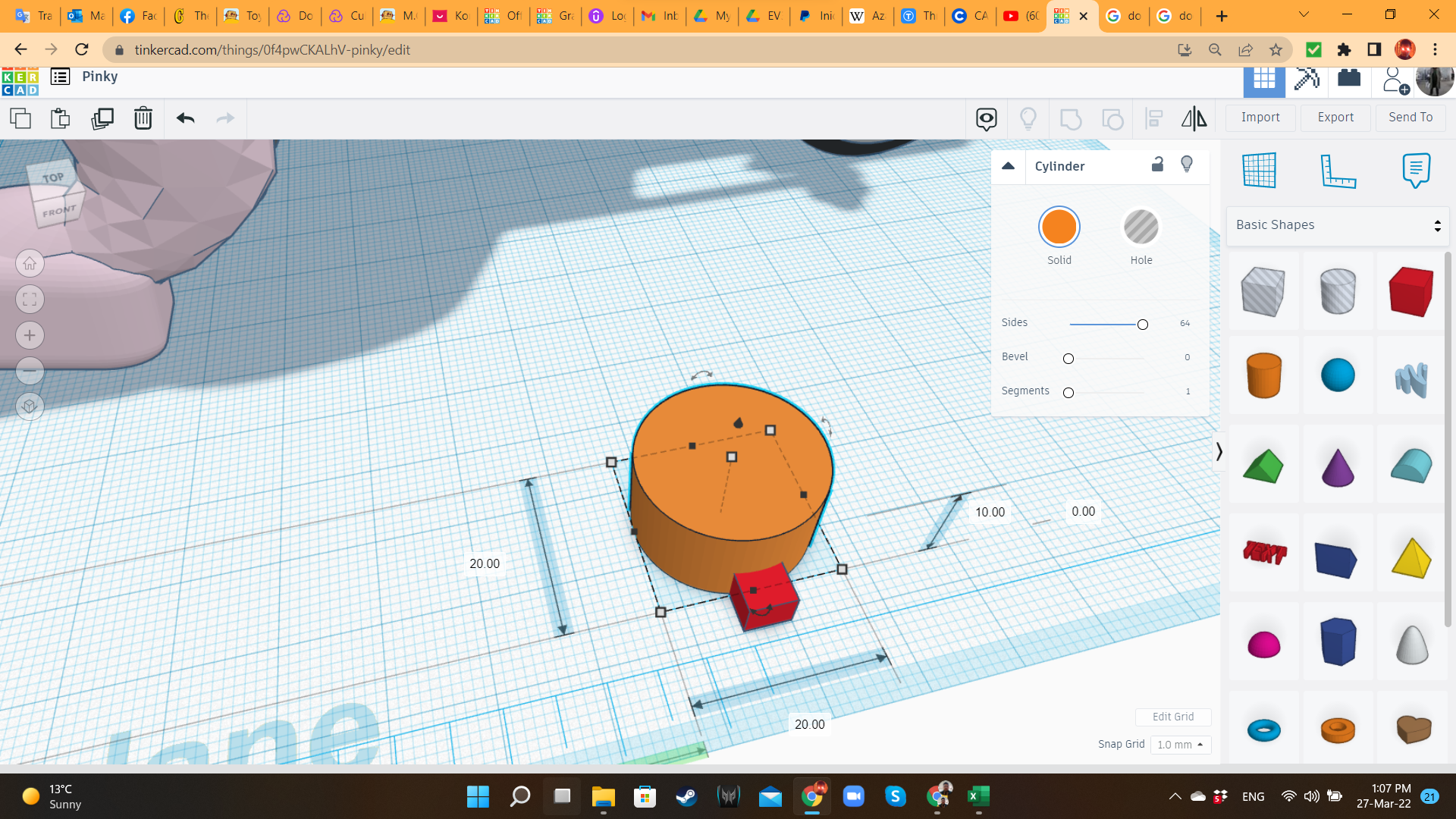
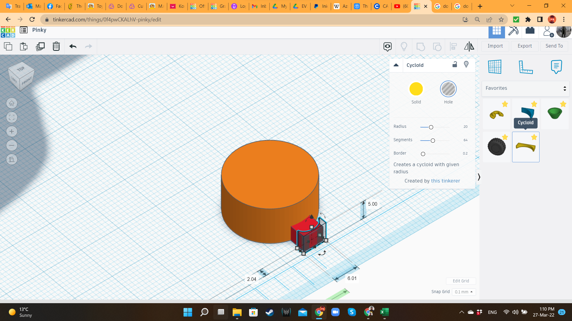
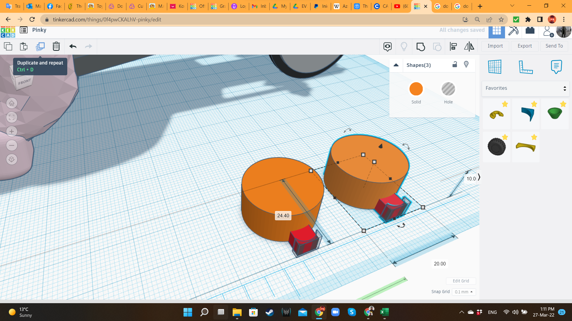
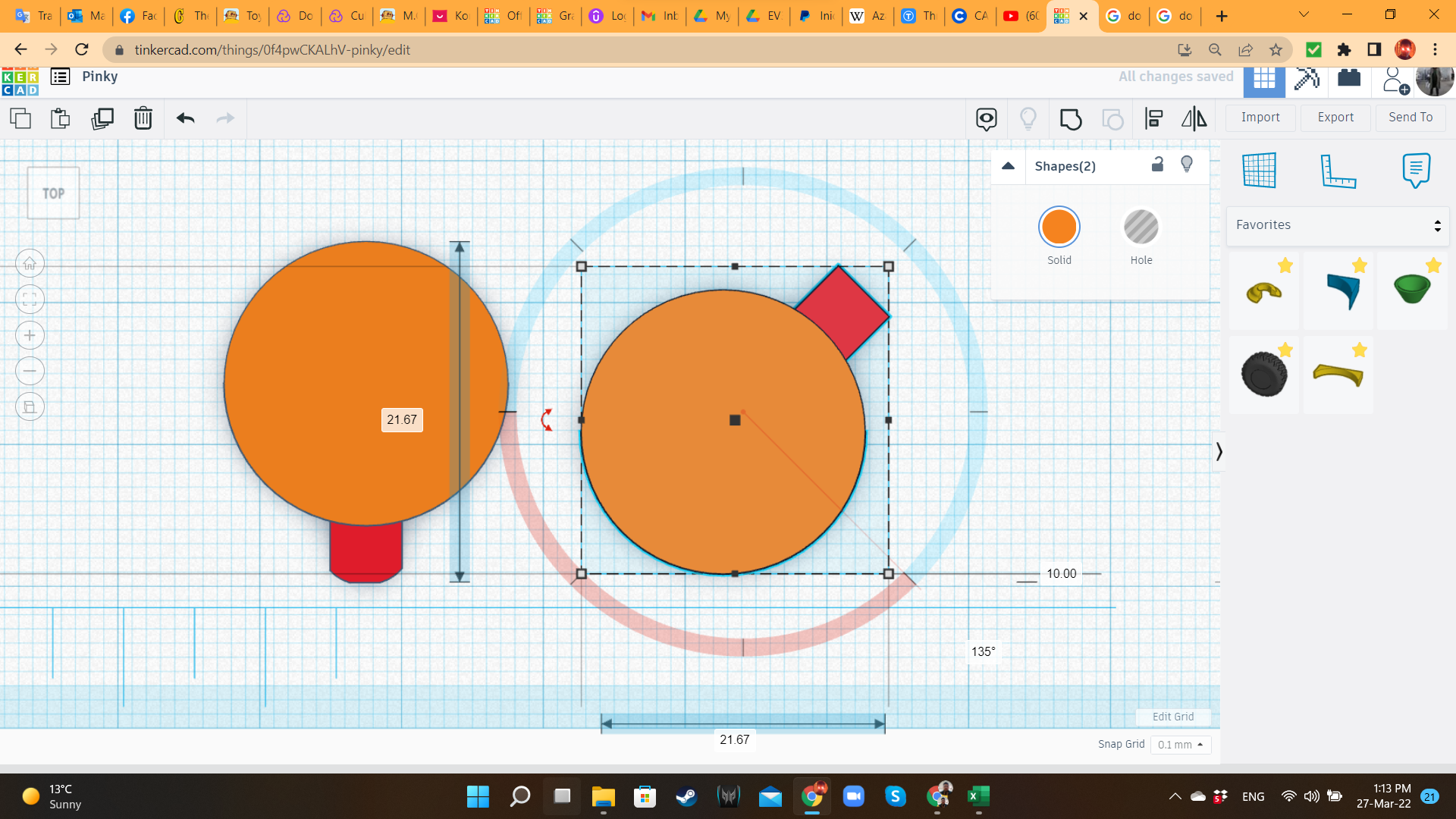
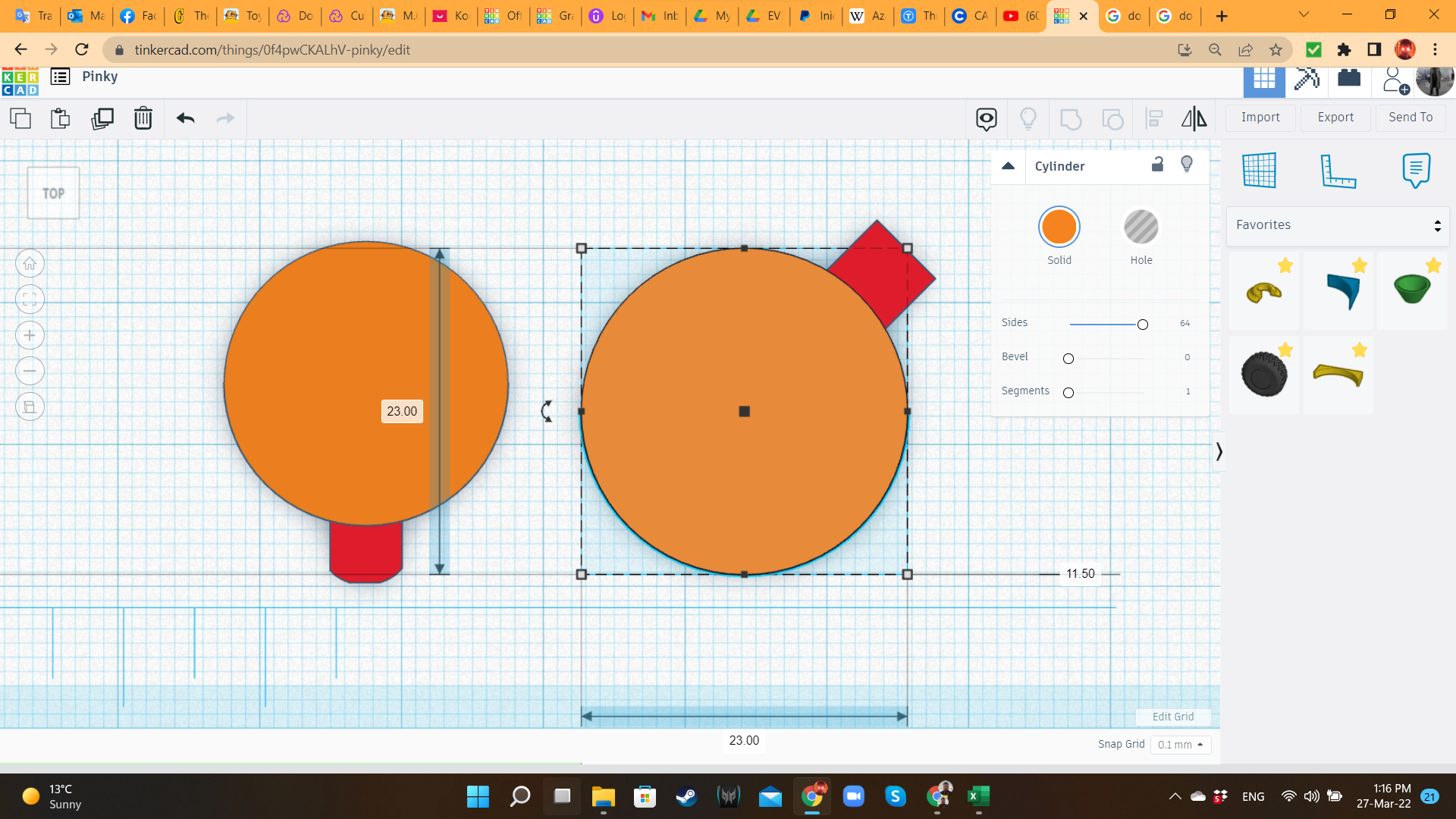
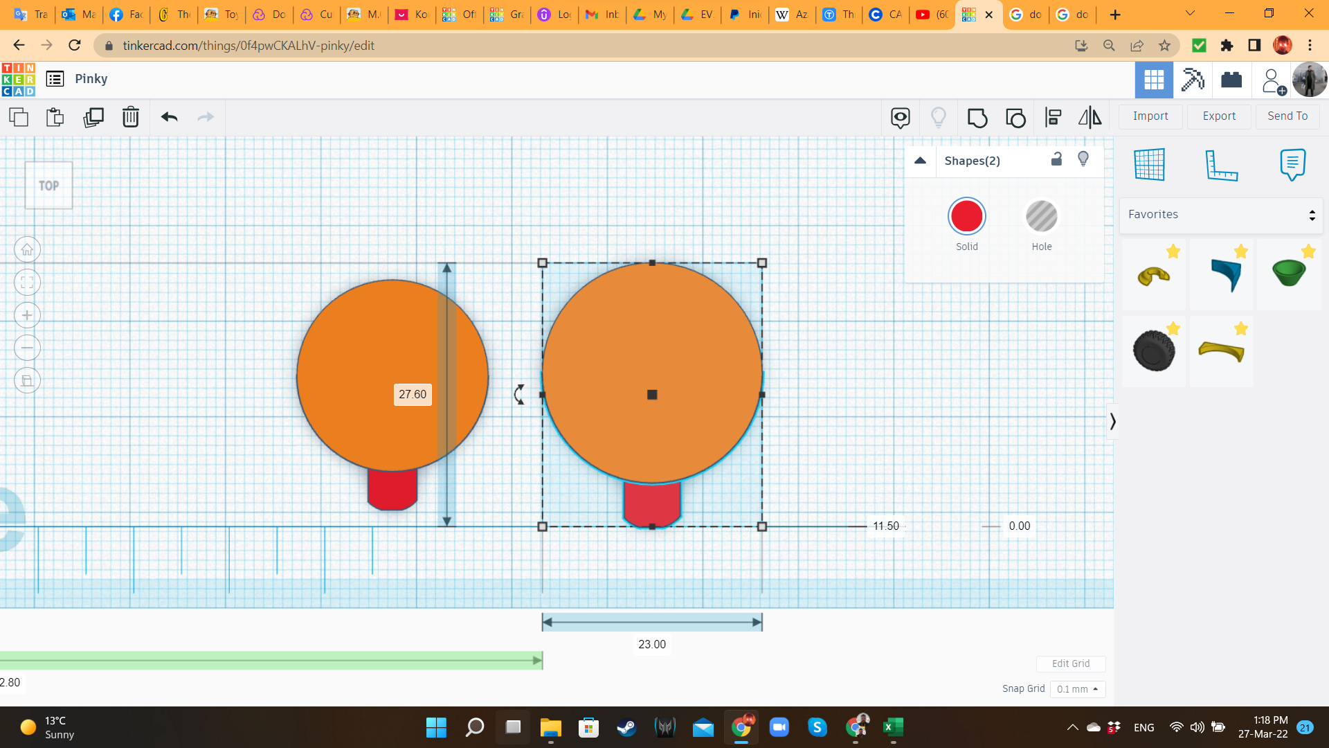
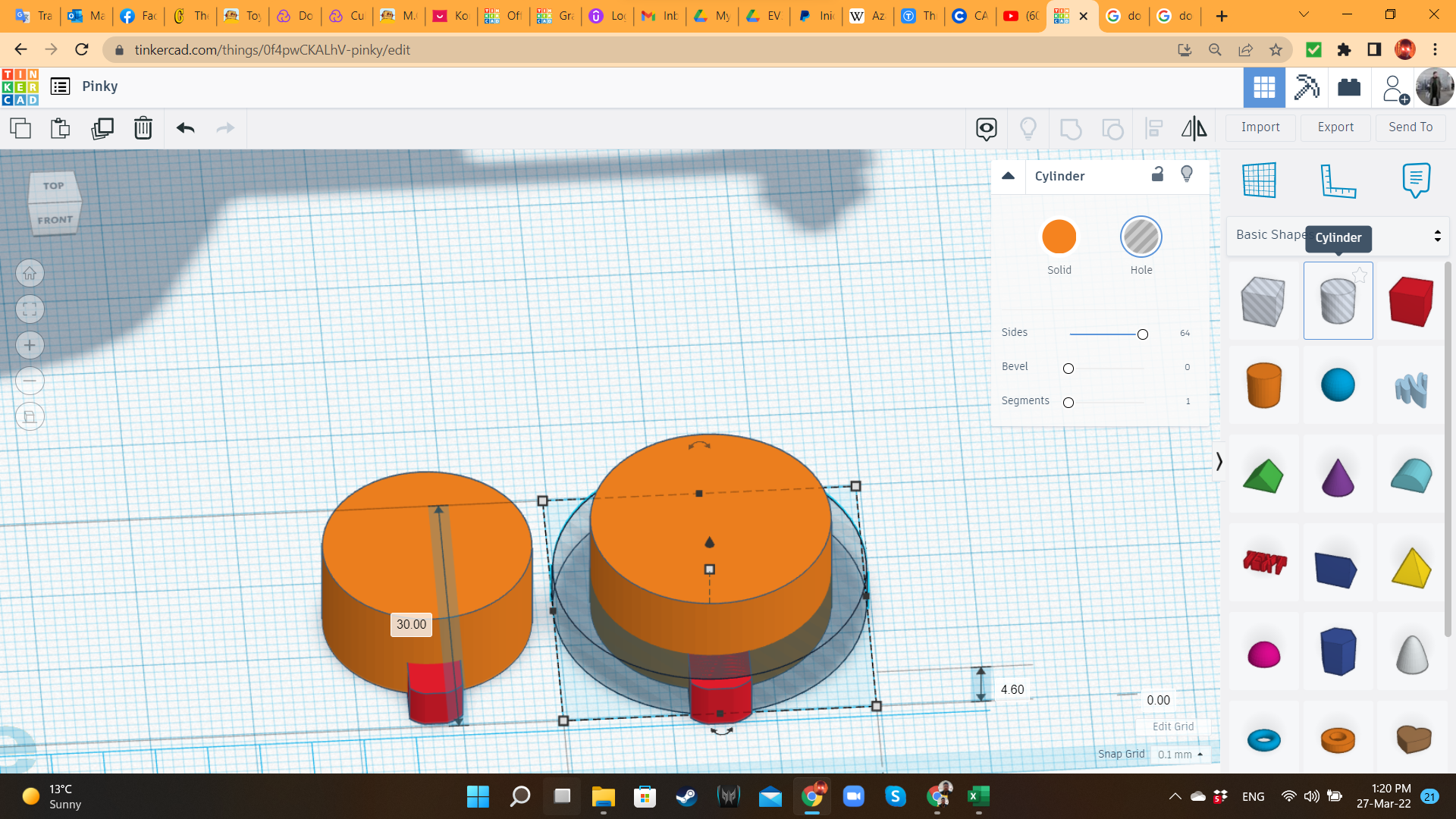
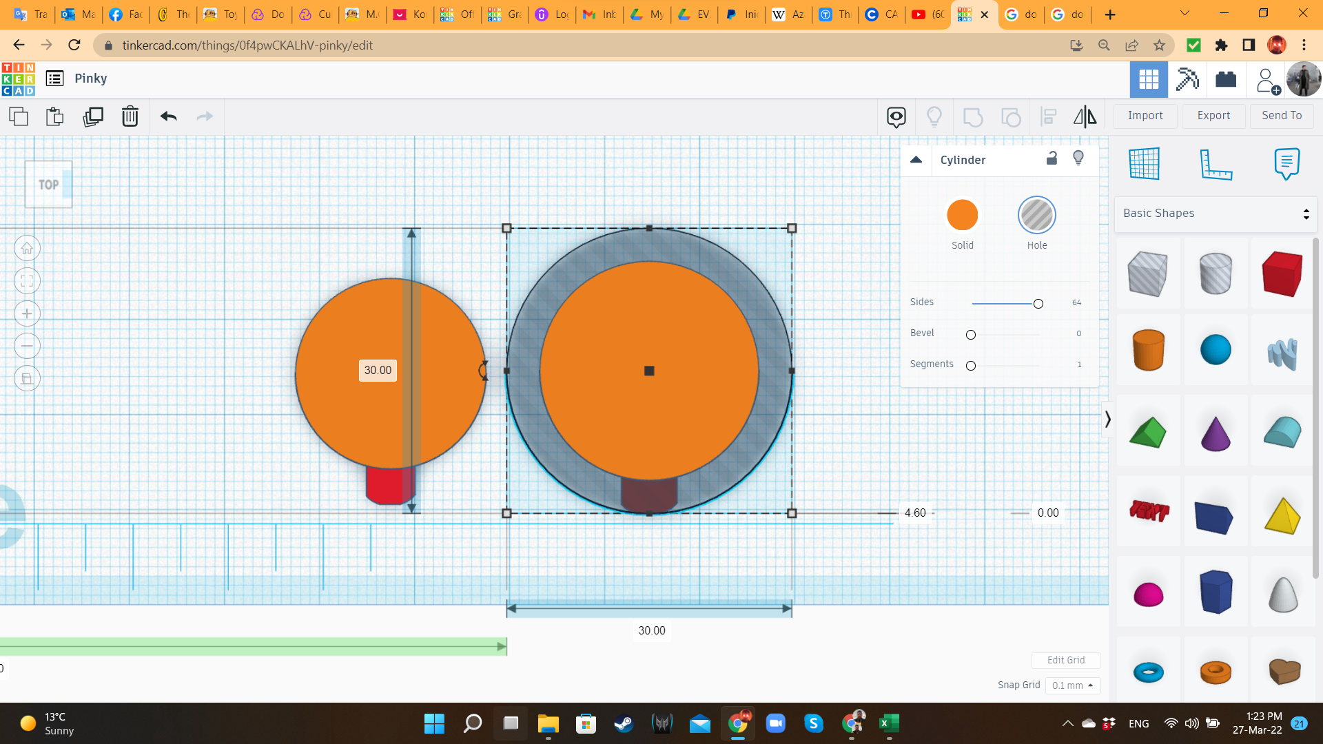
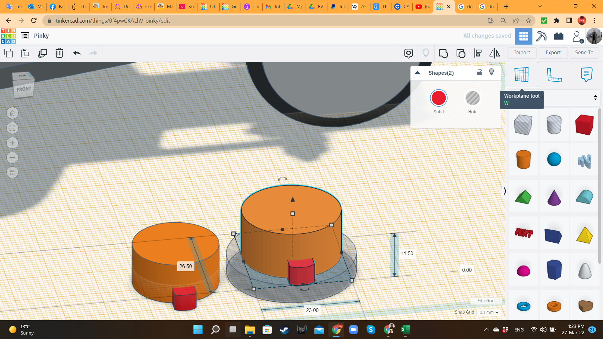
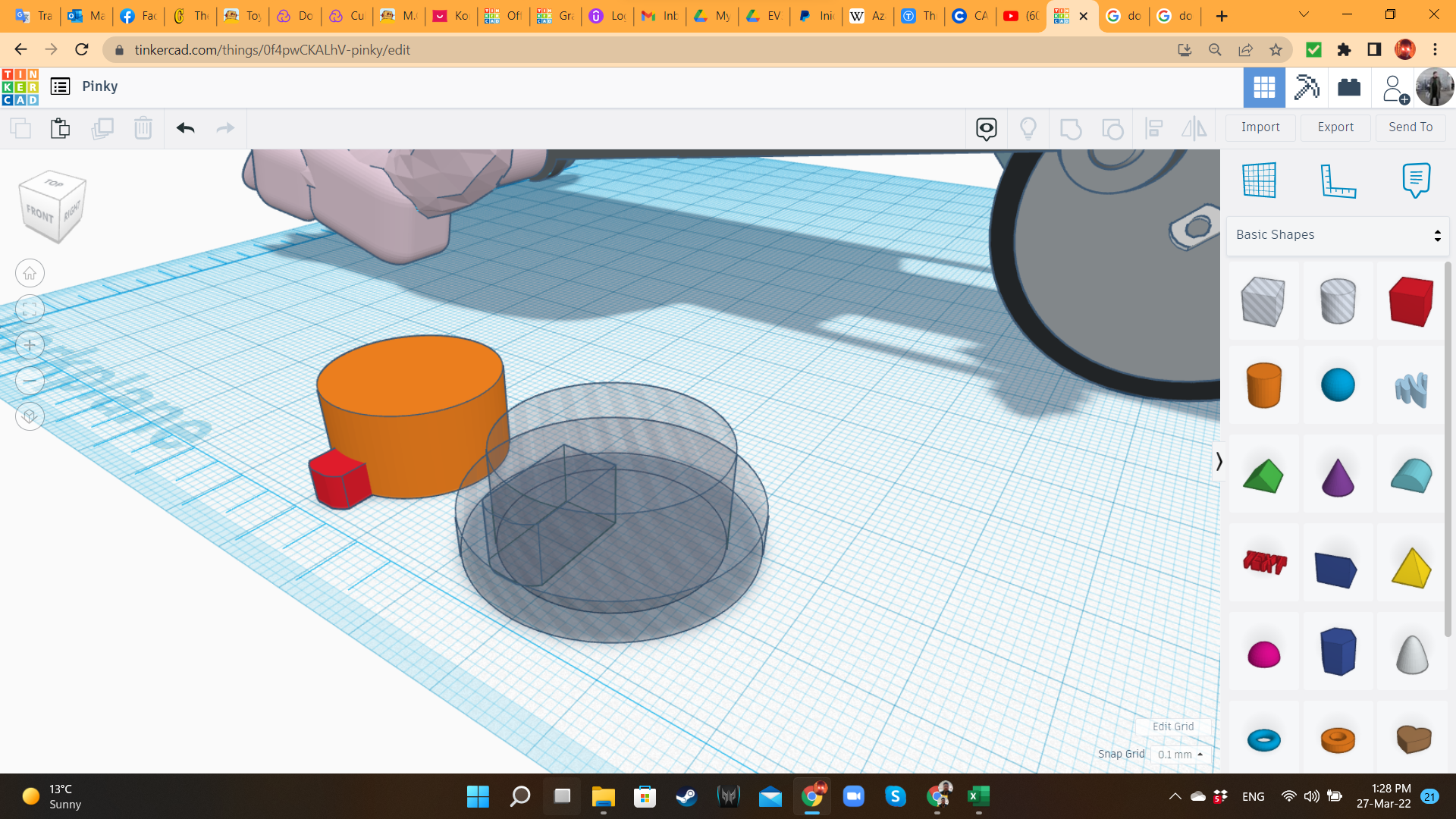
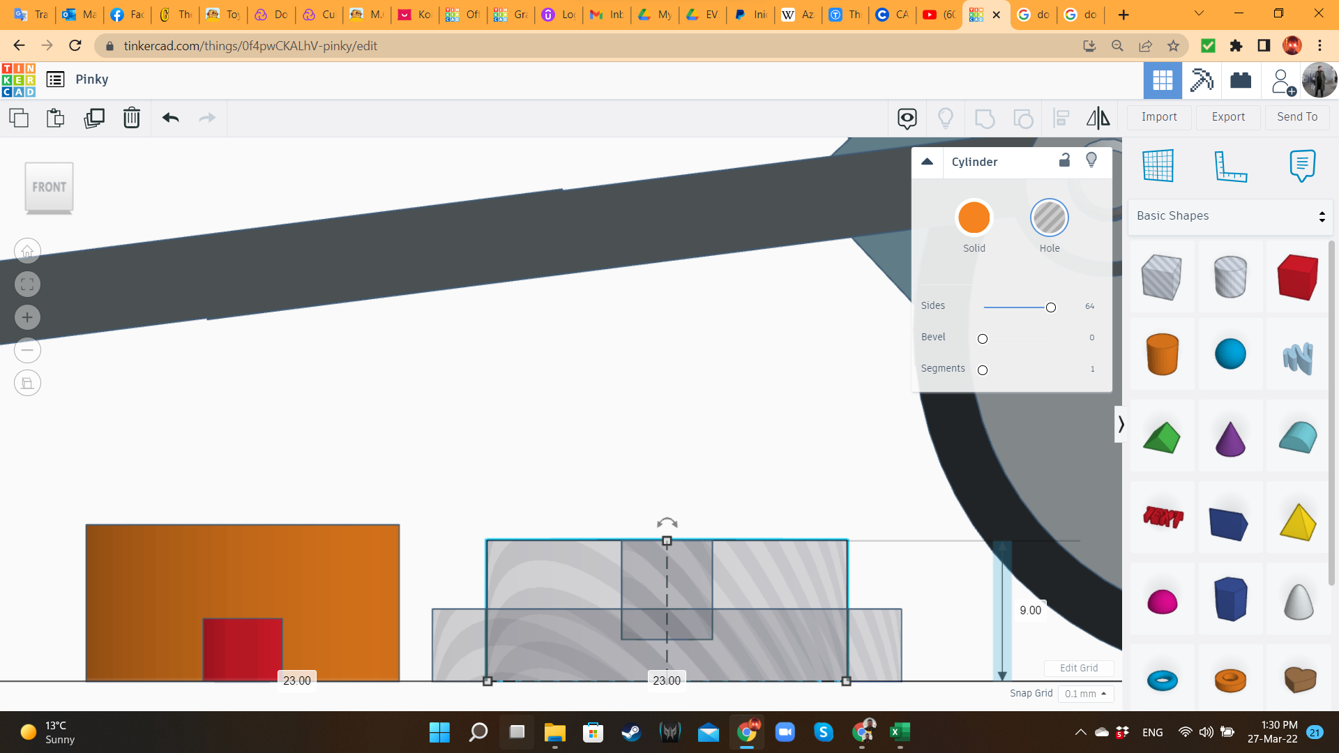
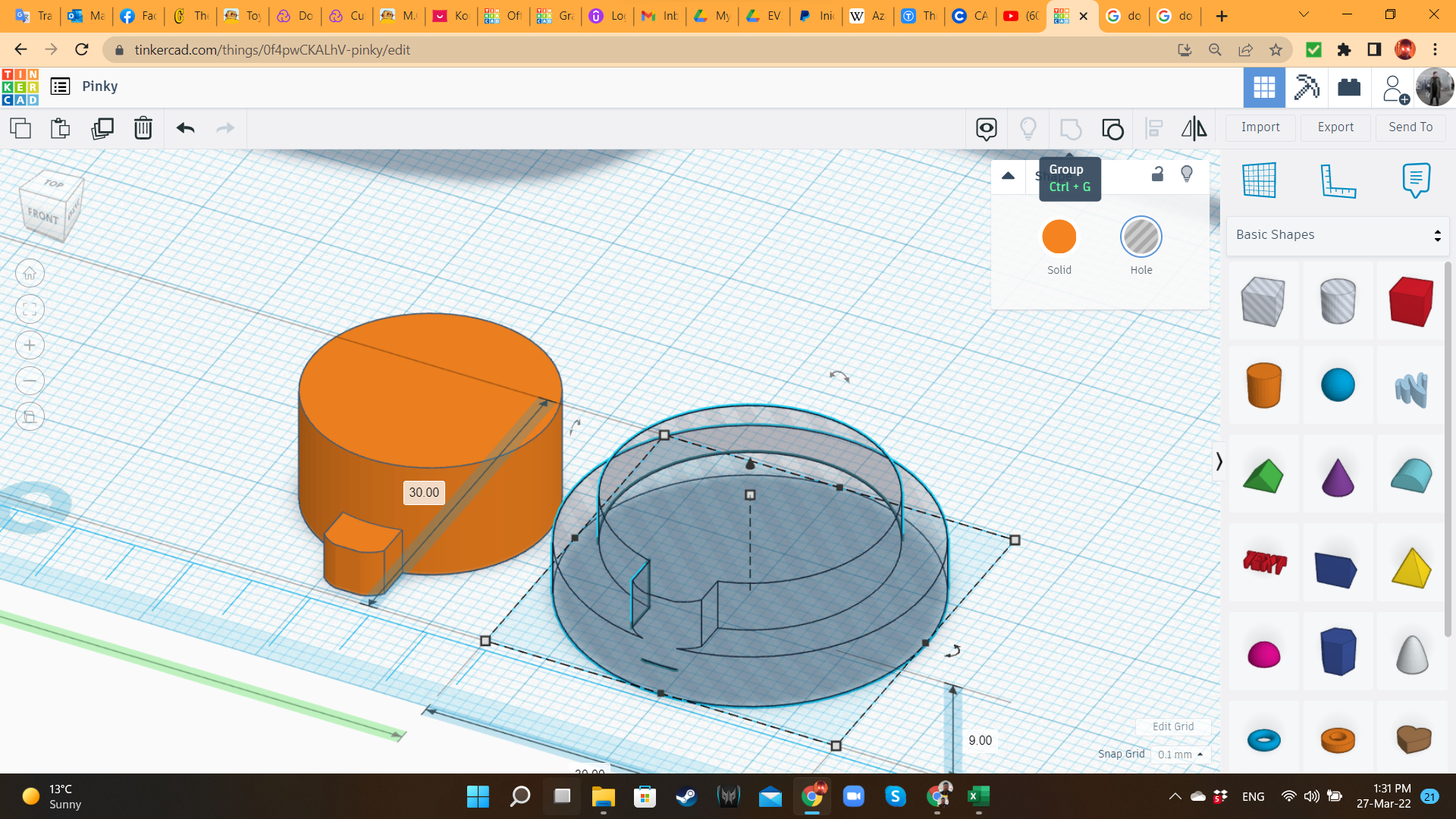
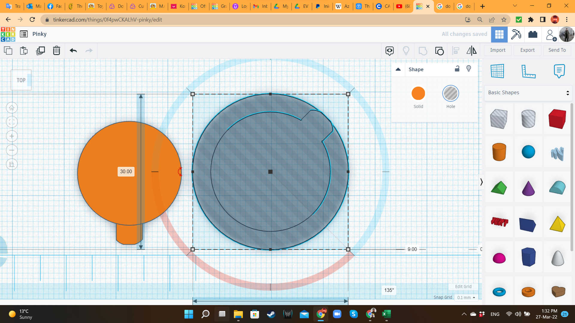
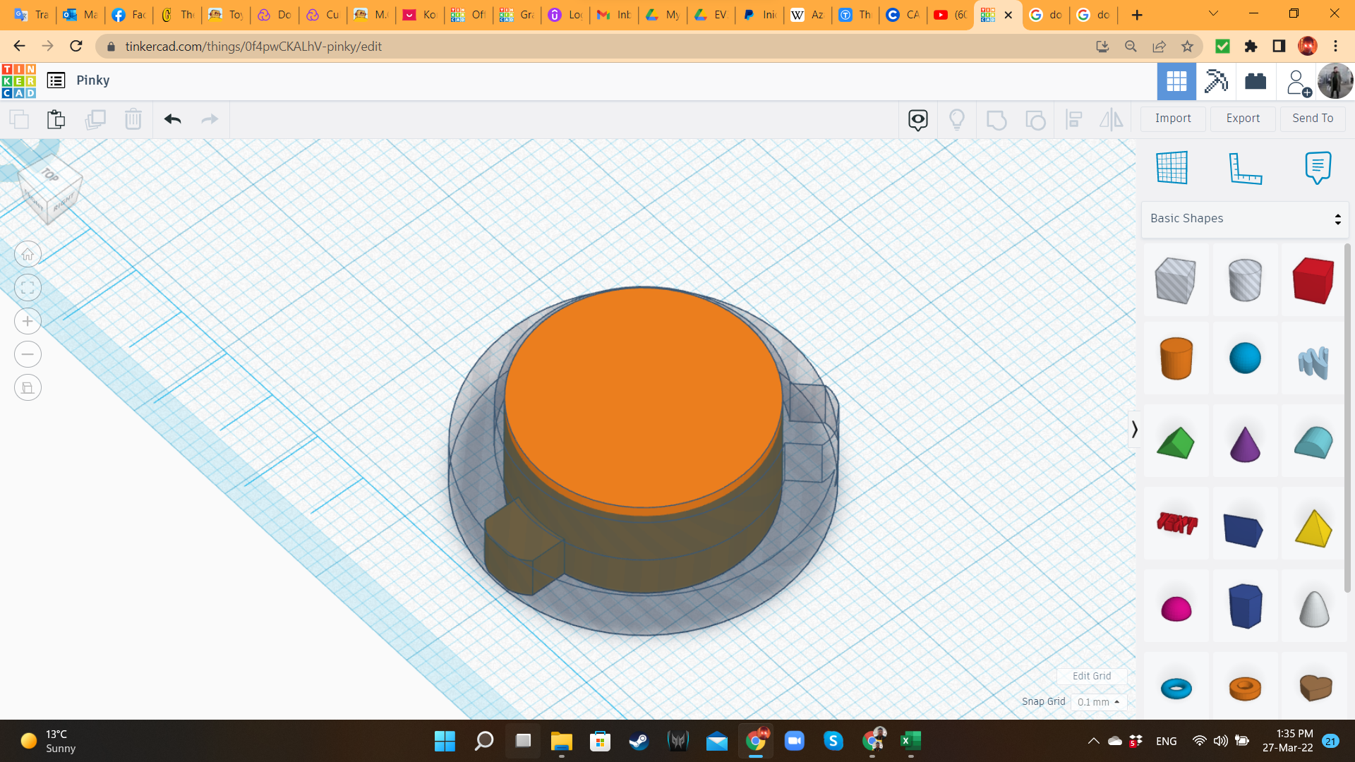
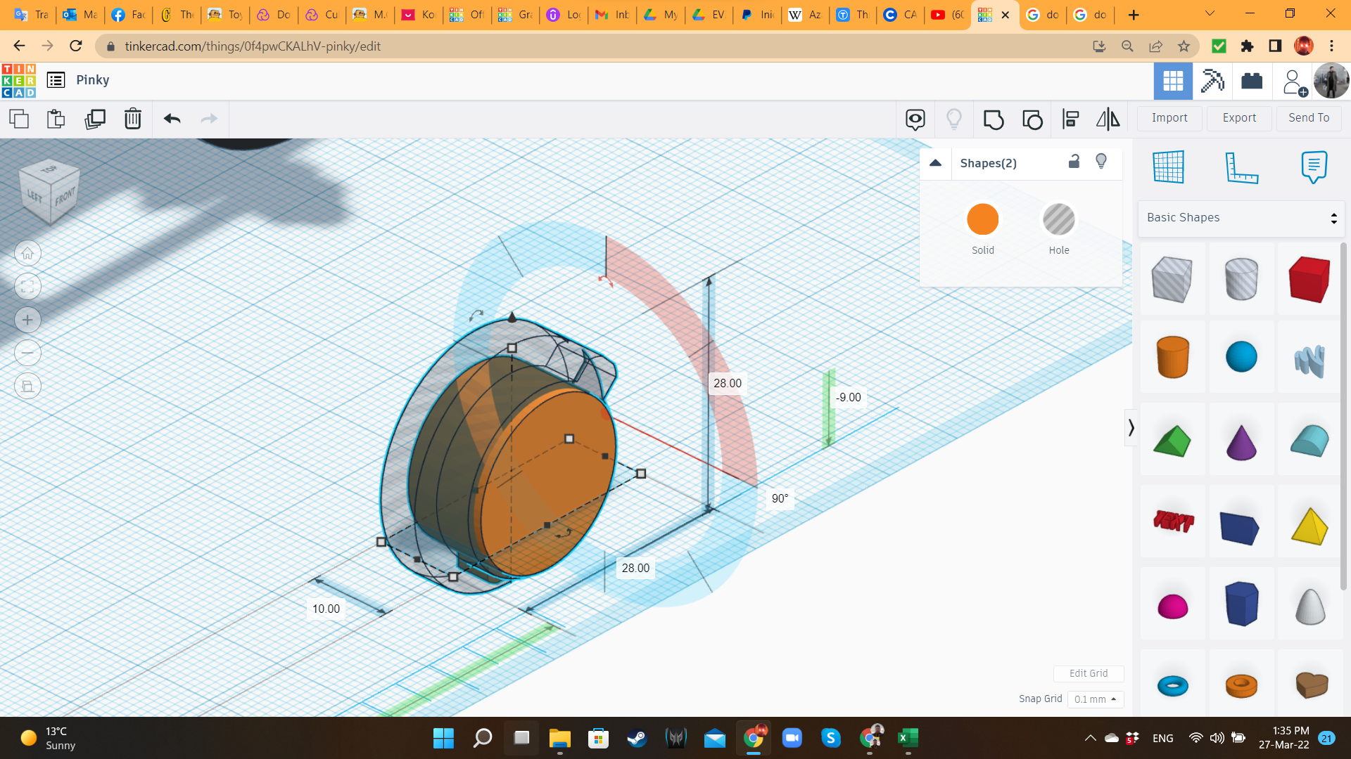
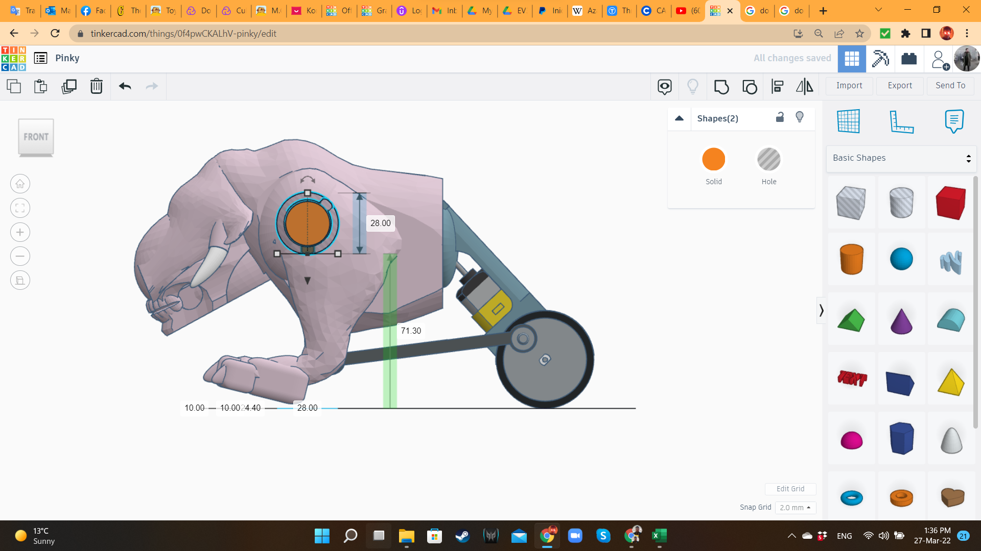
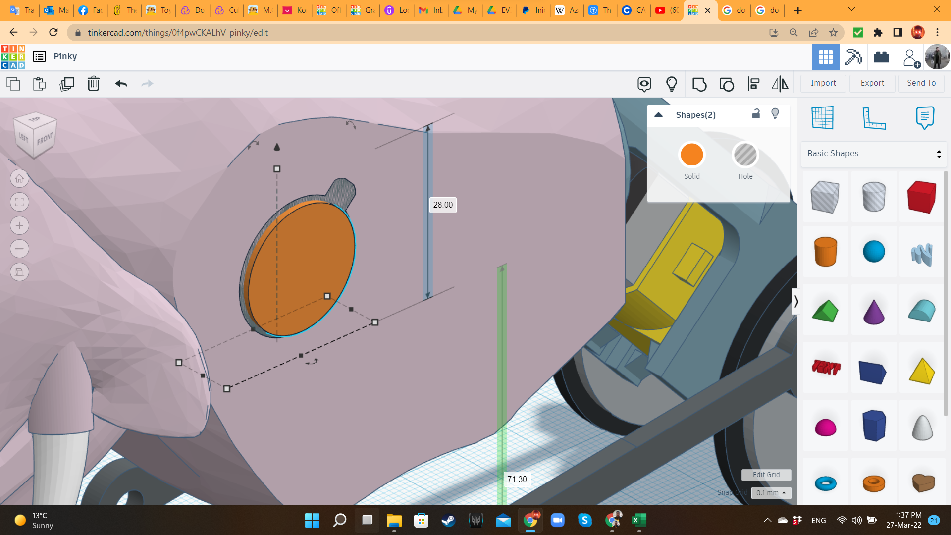
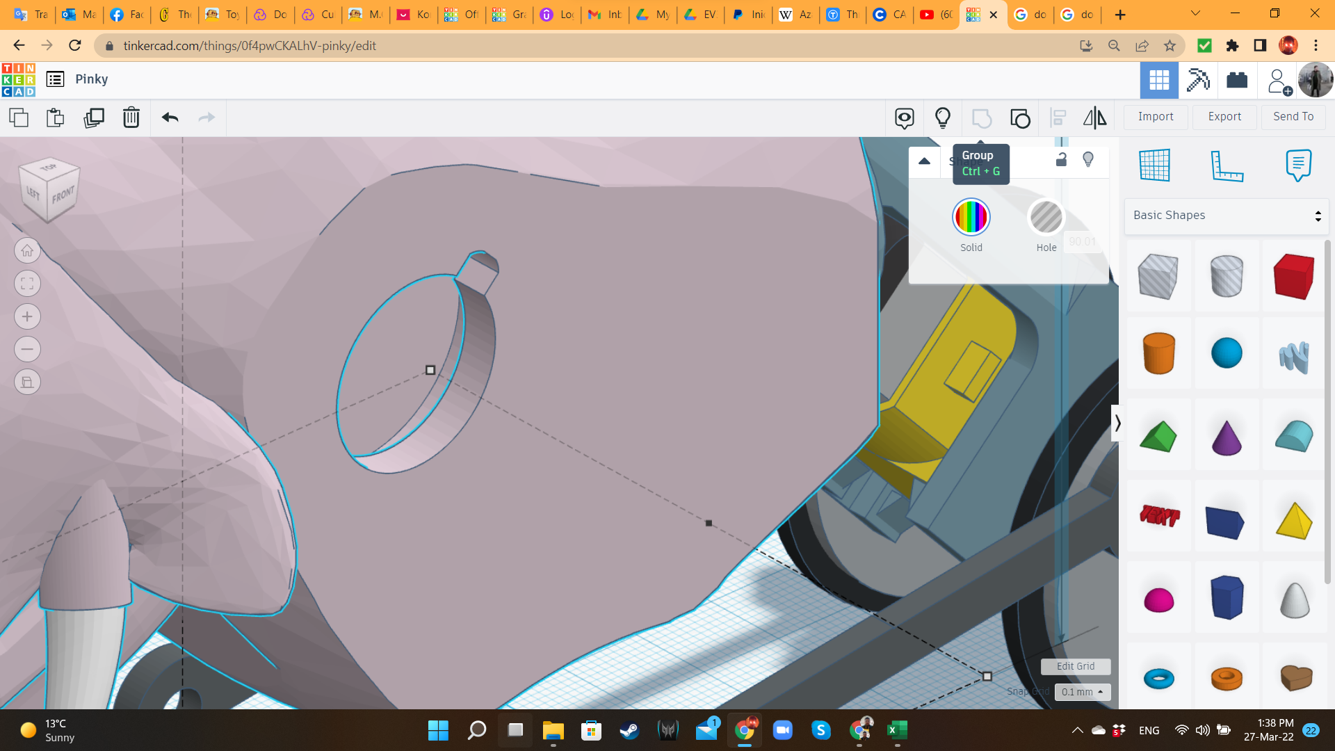
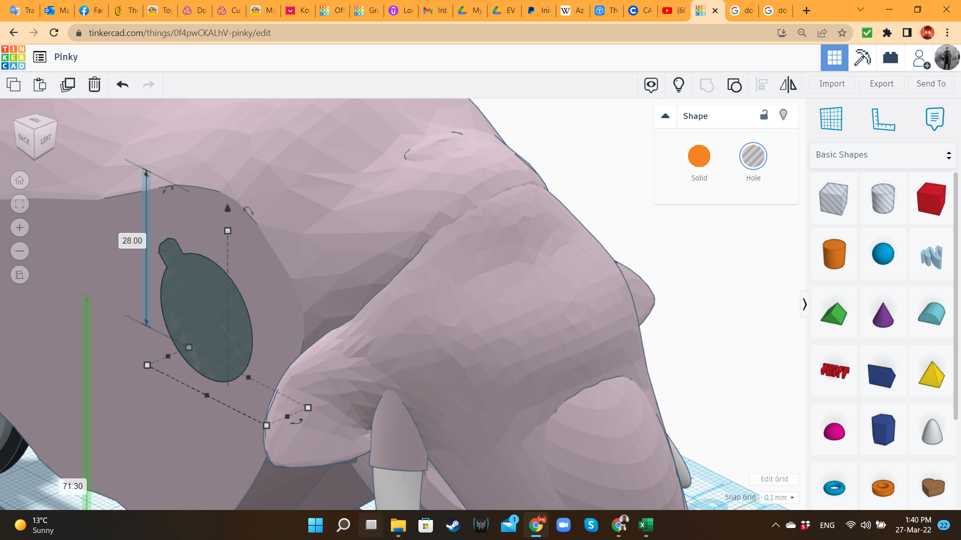
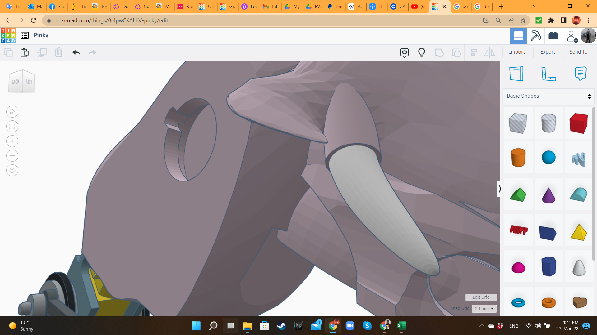
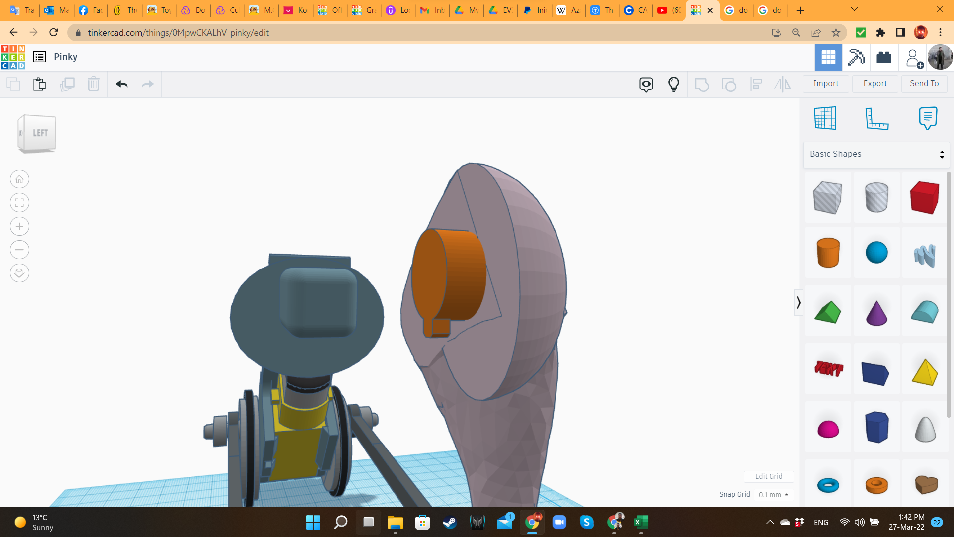
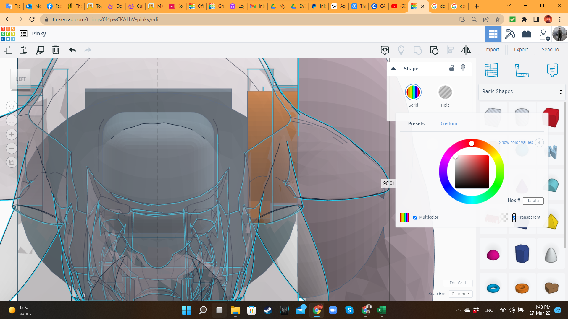
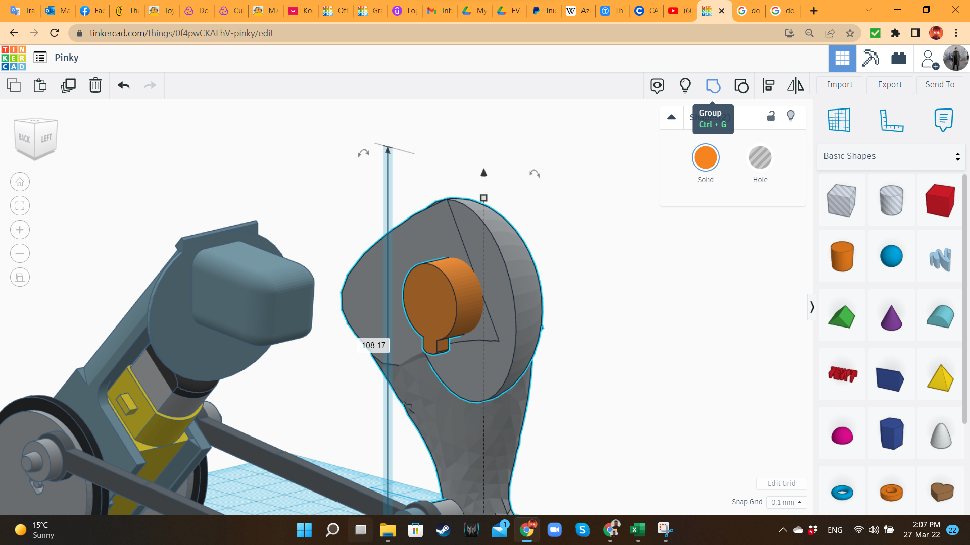
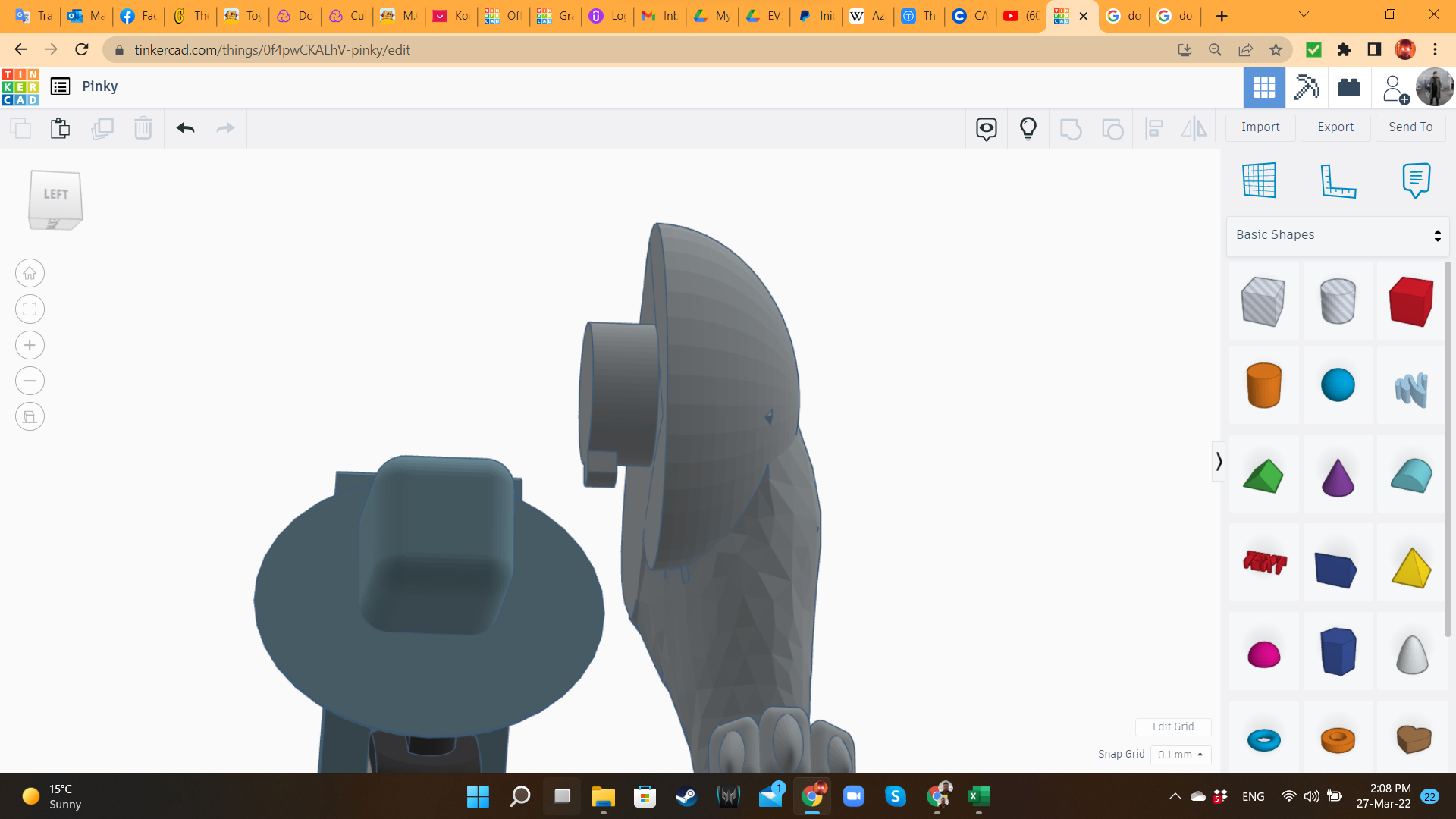
To attach the leg to the body, I created a joint system, based on cylinders. The body has a hole where the leg's cylinder matches and slides perfectly. The cylinder in the thigh has a tooth, that gets trapped once the leg joint is inserted.
Pinky 10: Second Leg
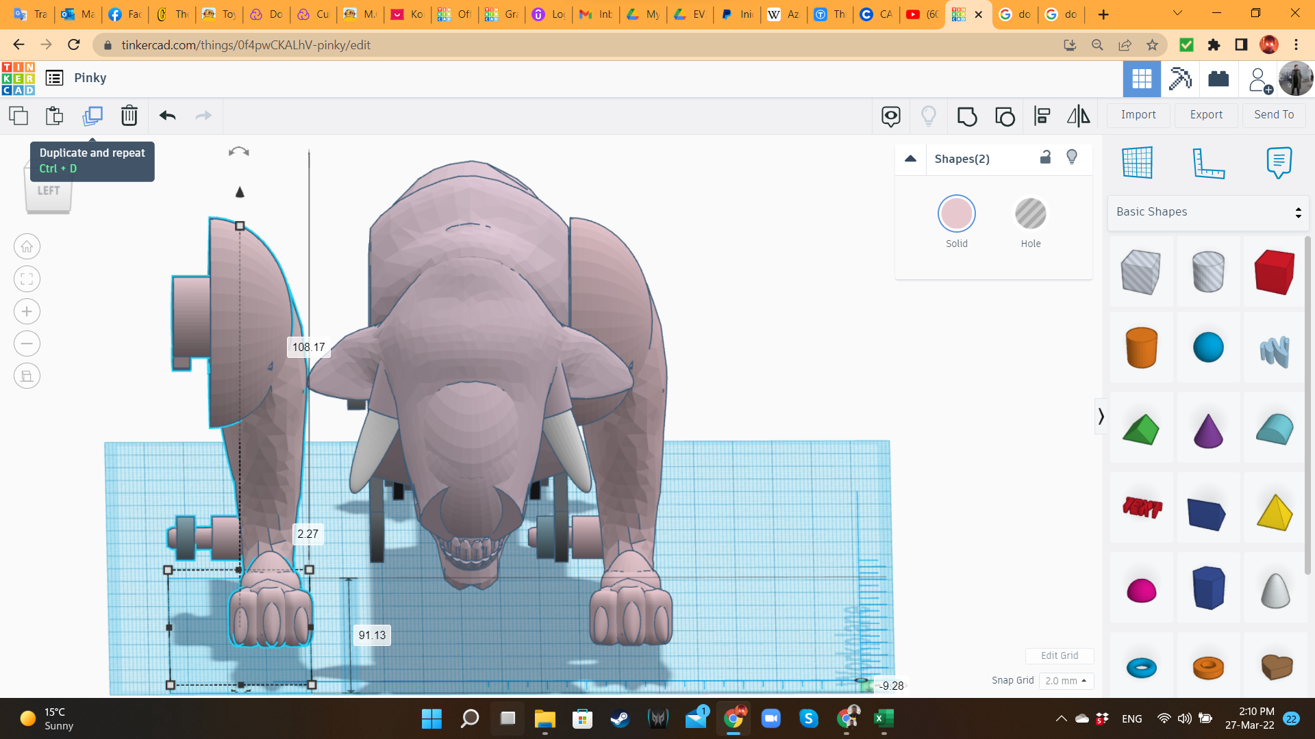
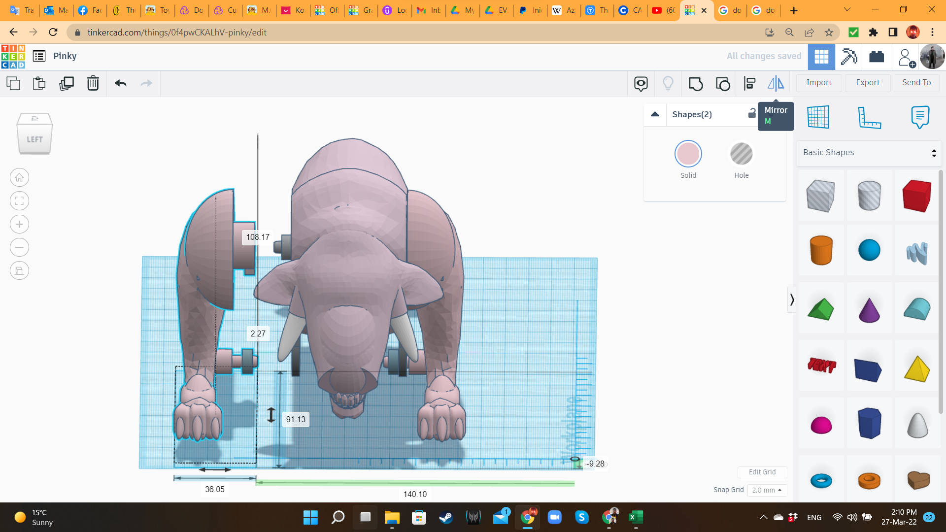
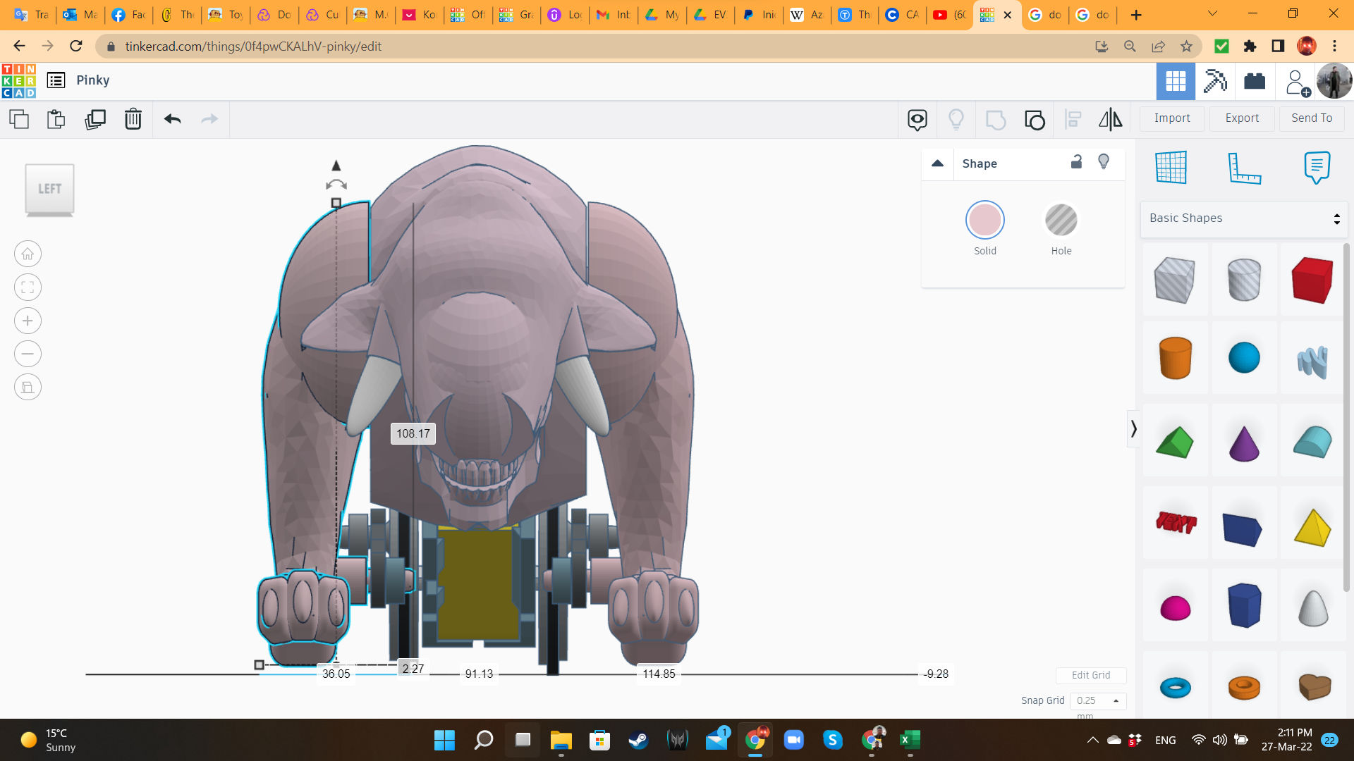
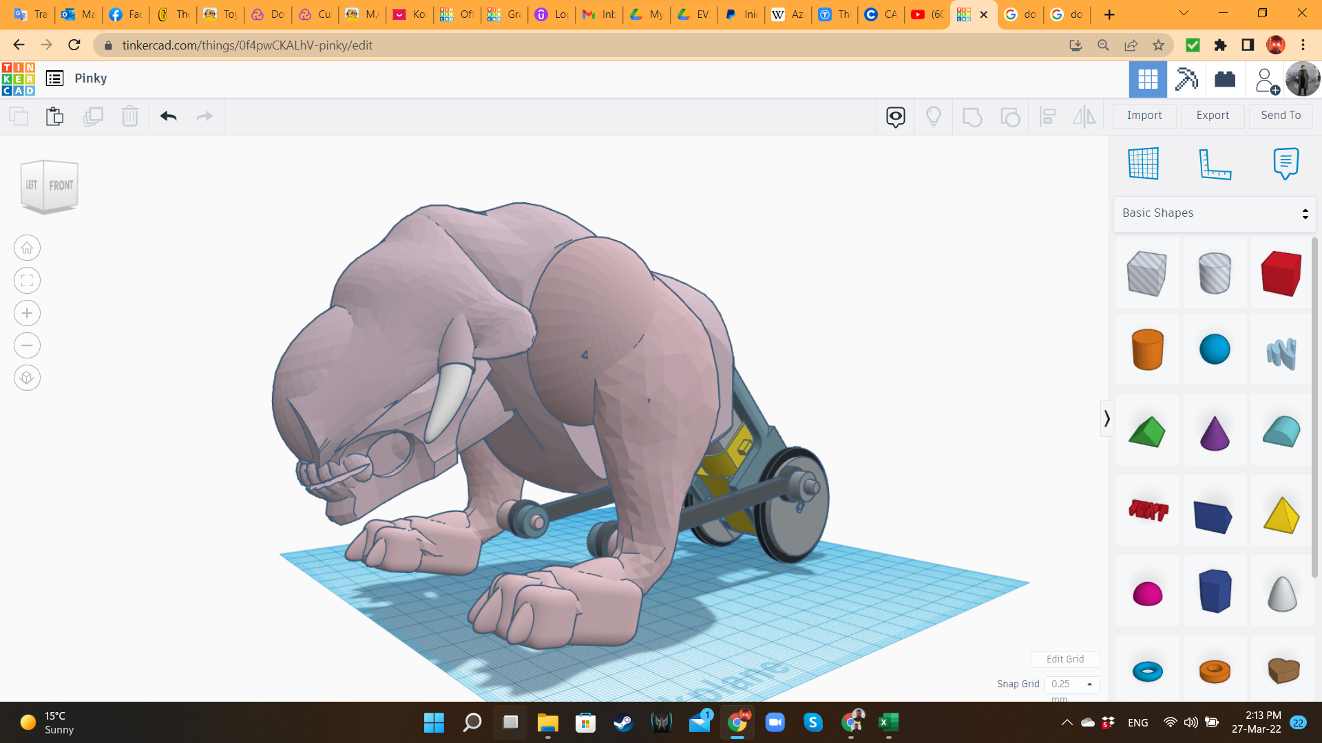
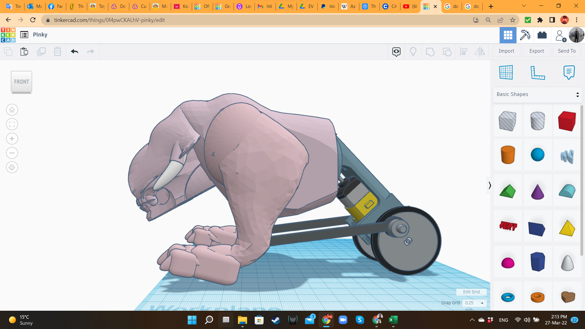
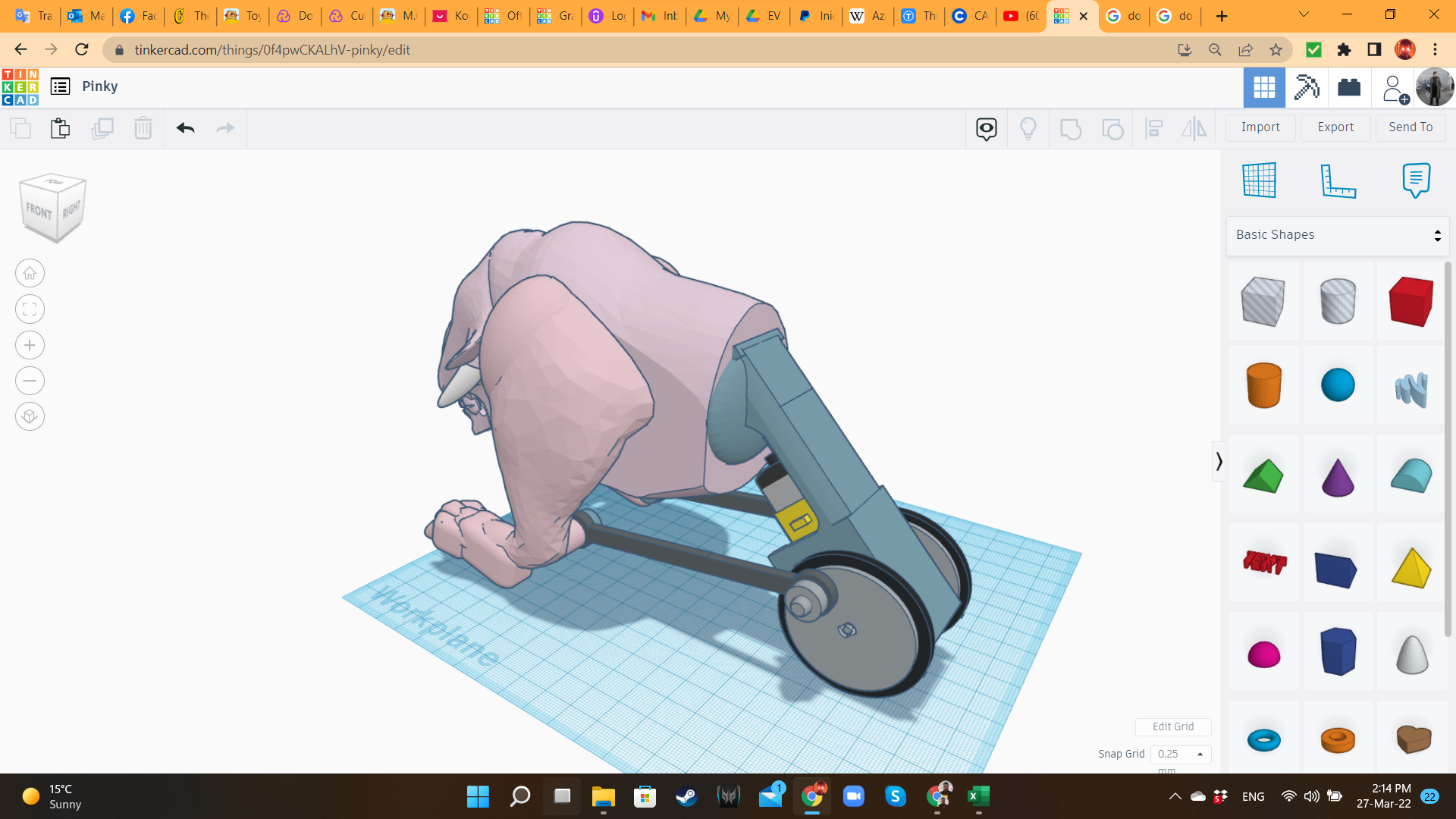
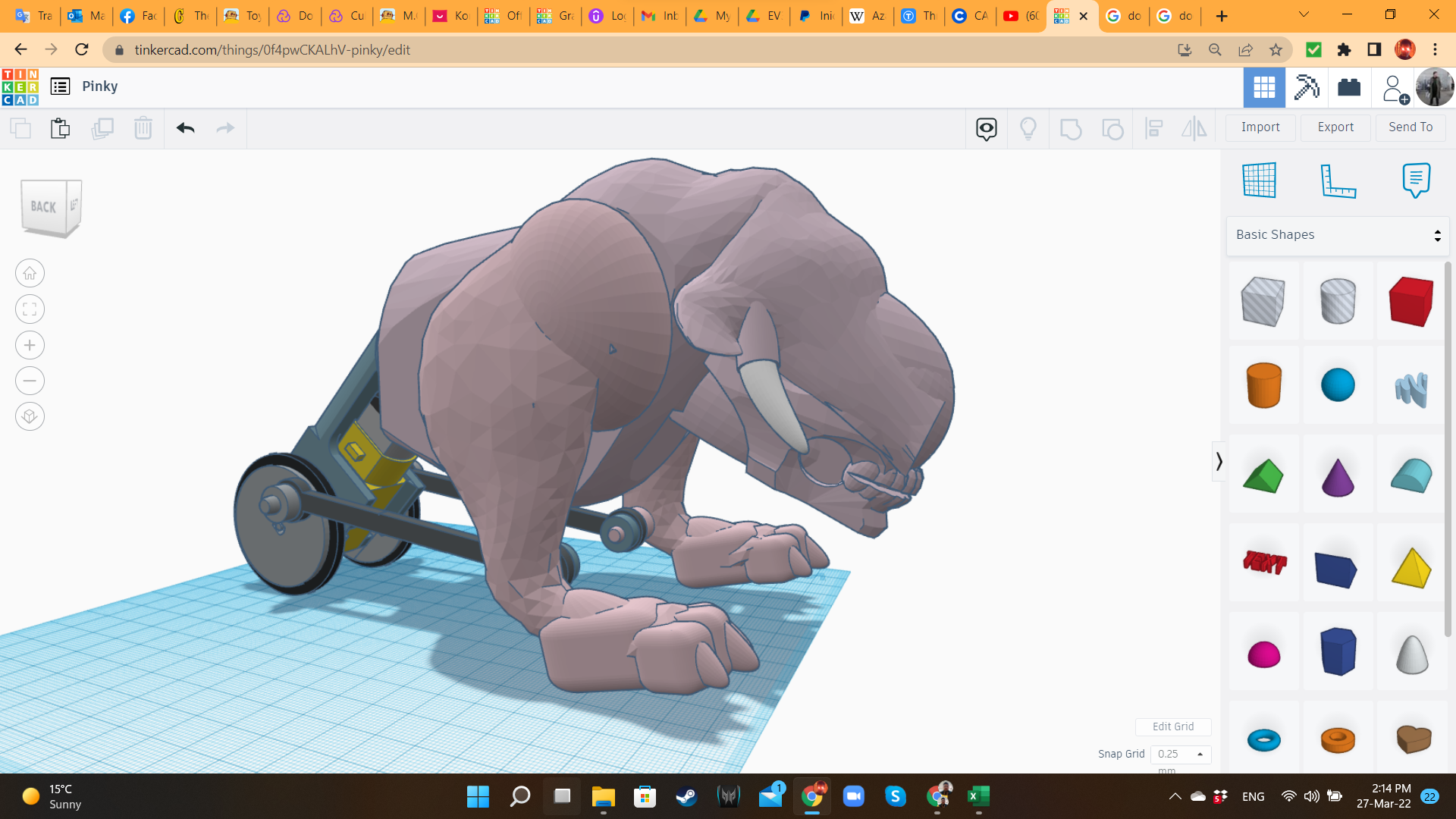
After finishing with the left leg and the joint, I duplicated and mirrored them, to create the right leg. The organic part is ready!
(I told you at the beginning: I had to sacrifice some animals to bring this creature to existence...)
Pinky 11: Extra Details for the Motor
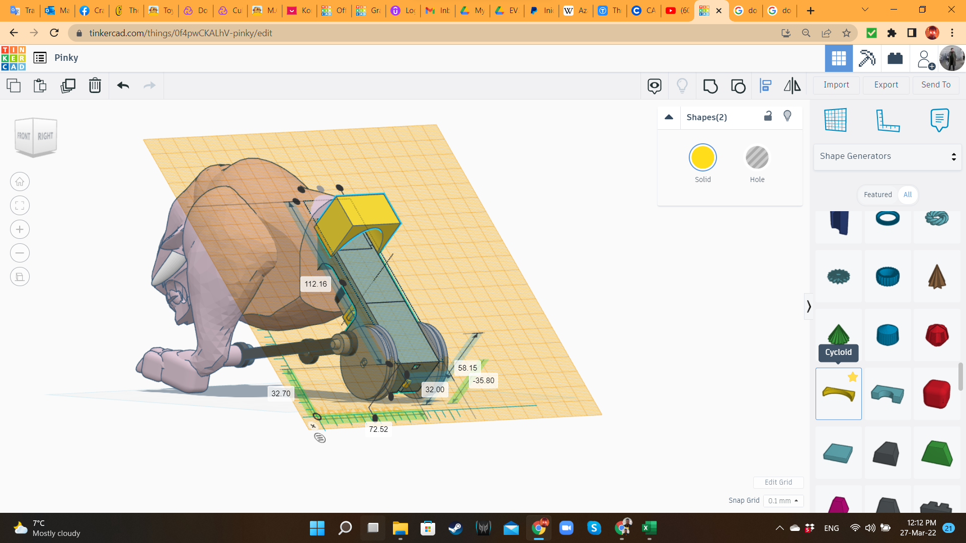
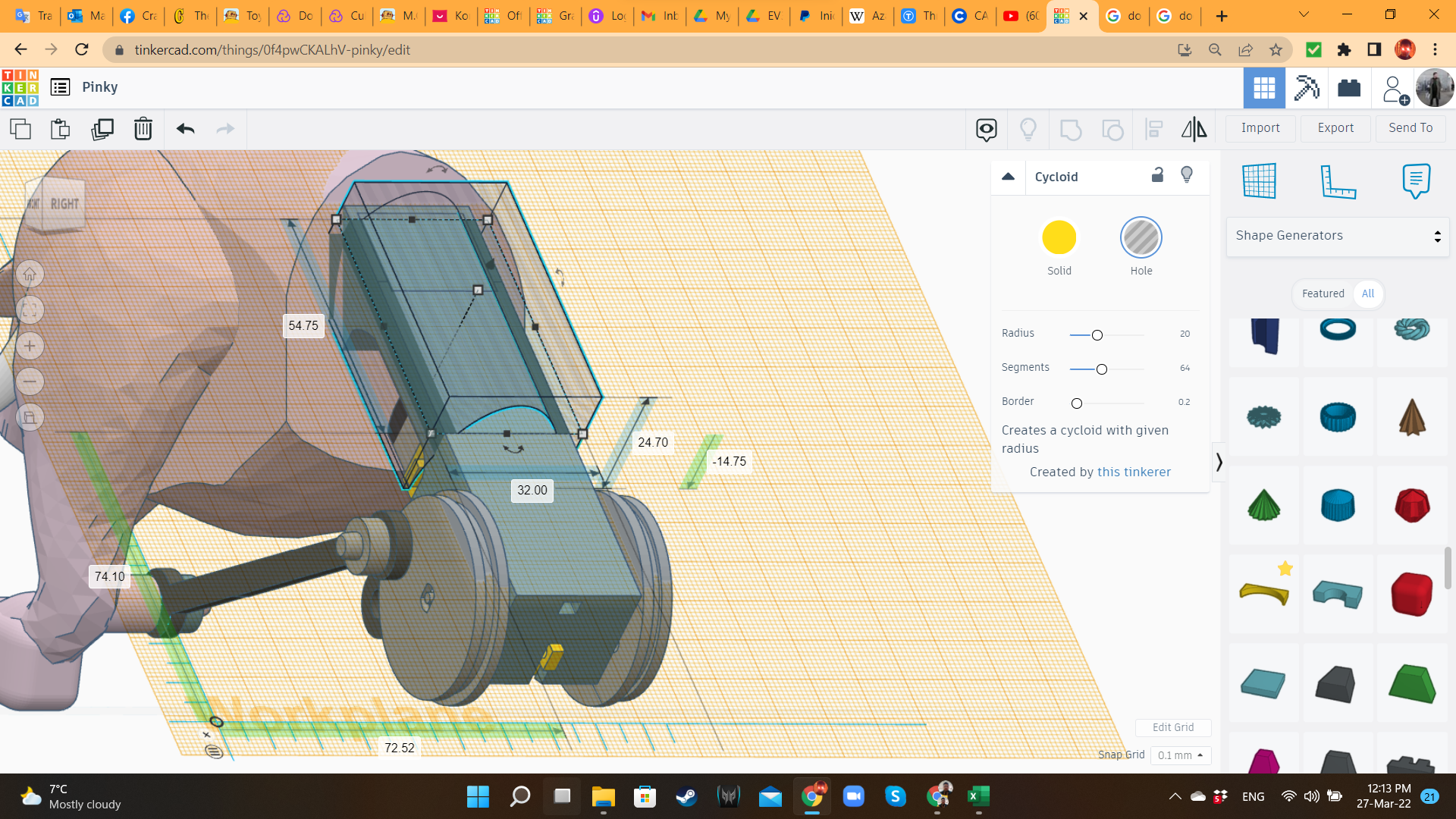
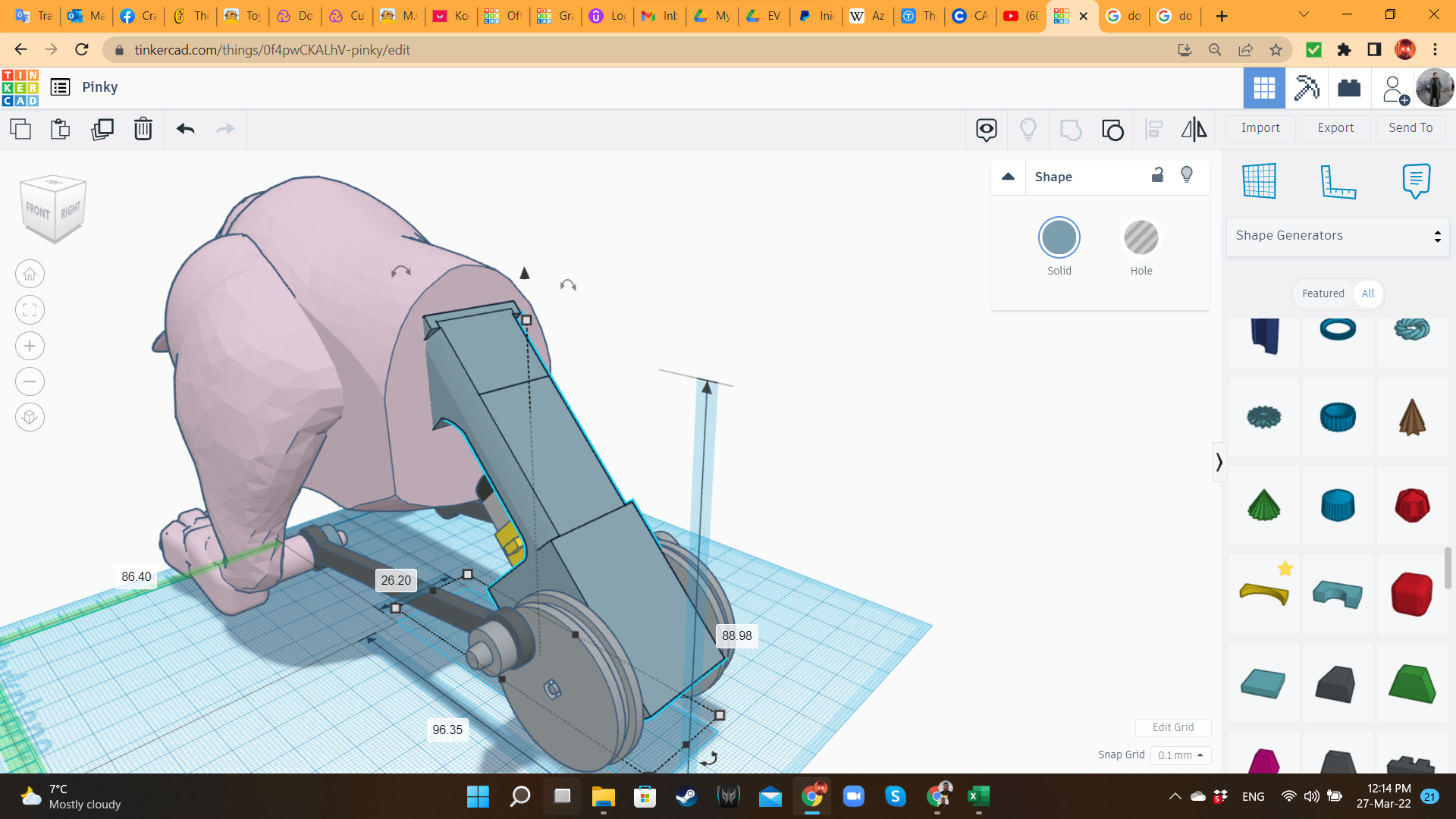
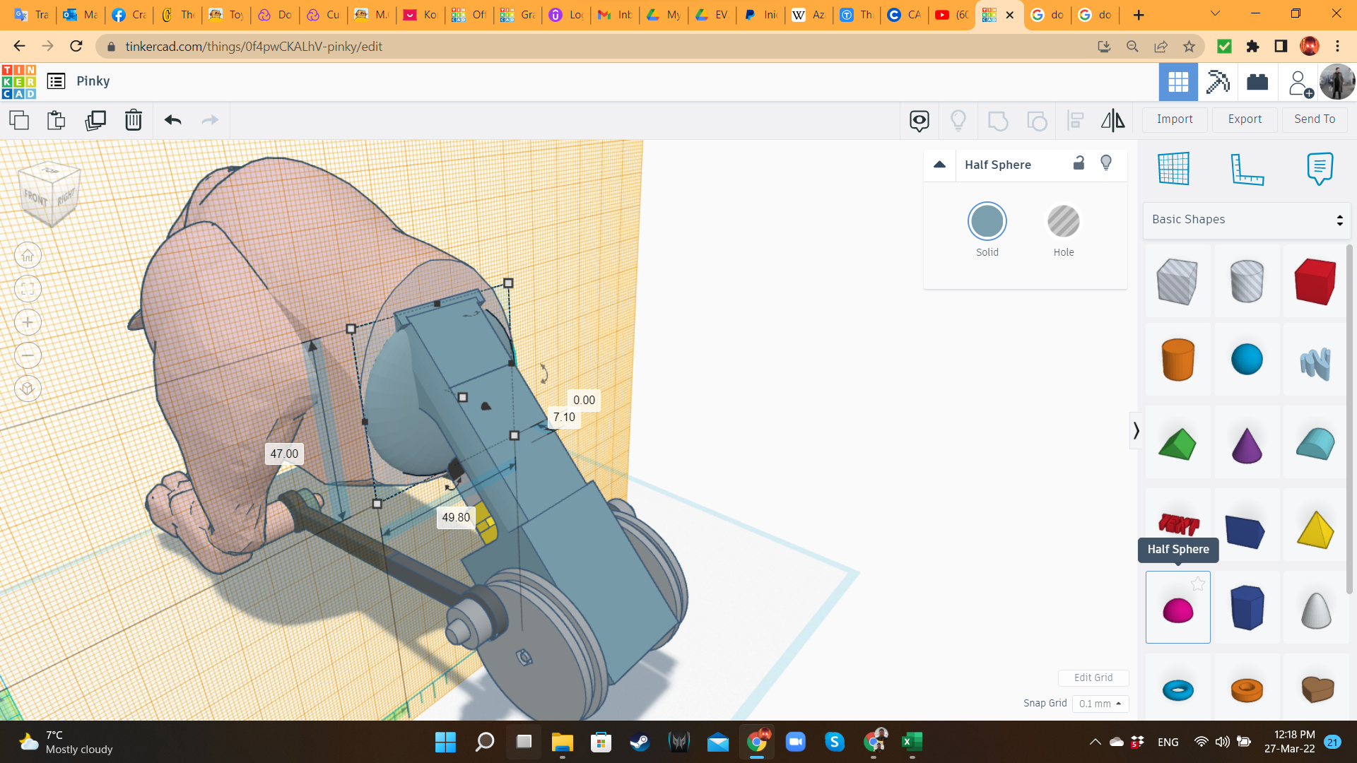
Now that I finished the organic part, I added some details to the motor part, like a MetaFillet hole to add curvature, and a Half-Sphere for better aesthetics in the union motor/organic body.
Battle Track 1: the Platform
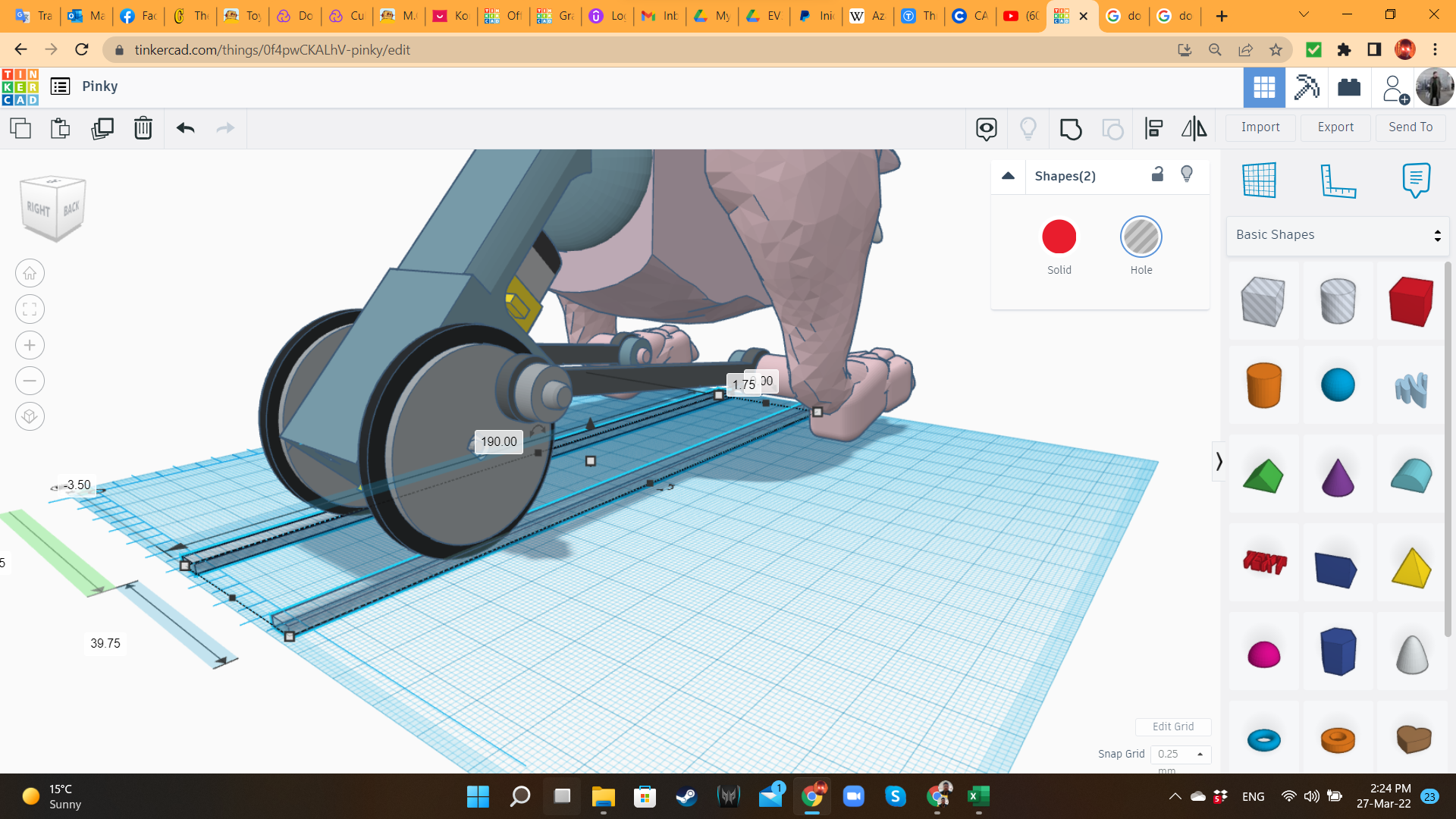
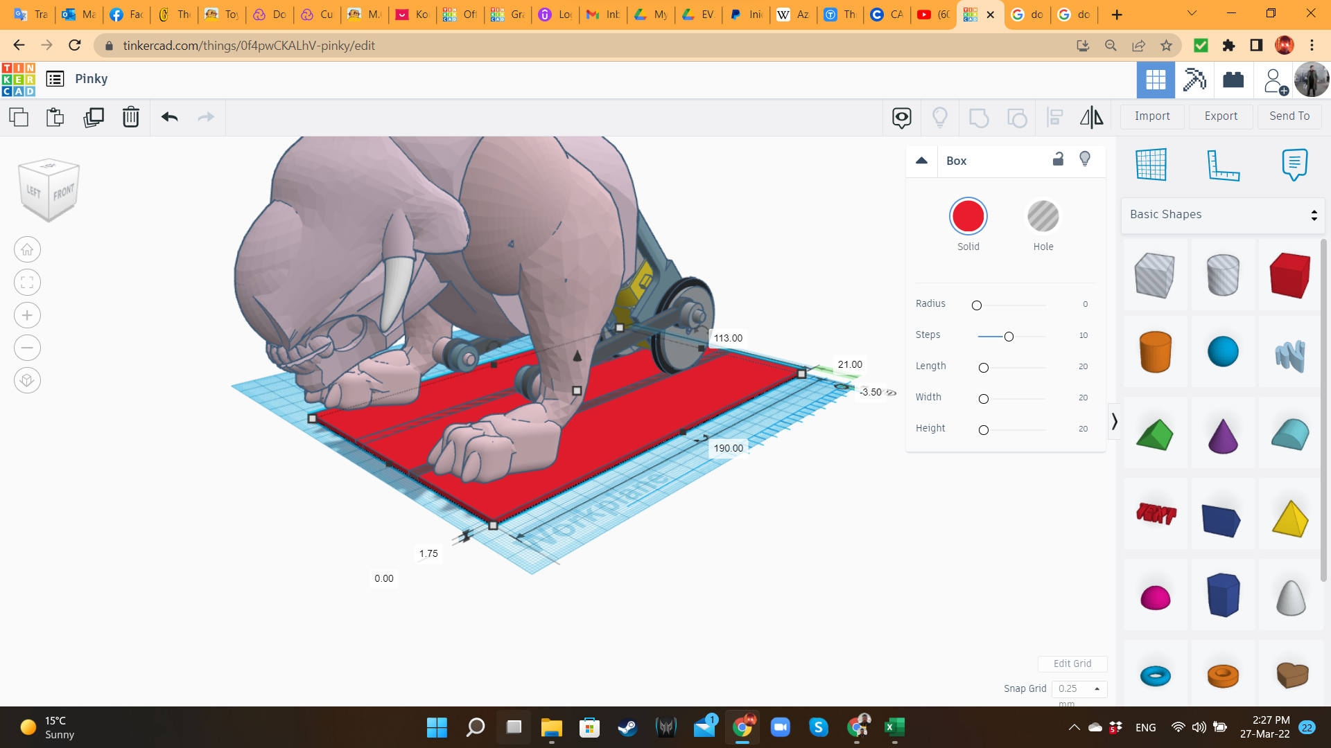
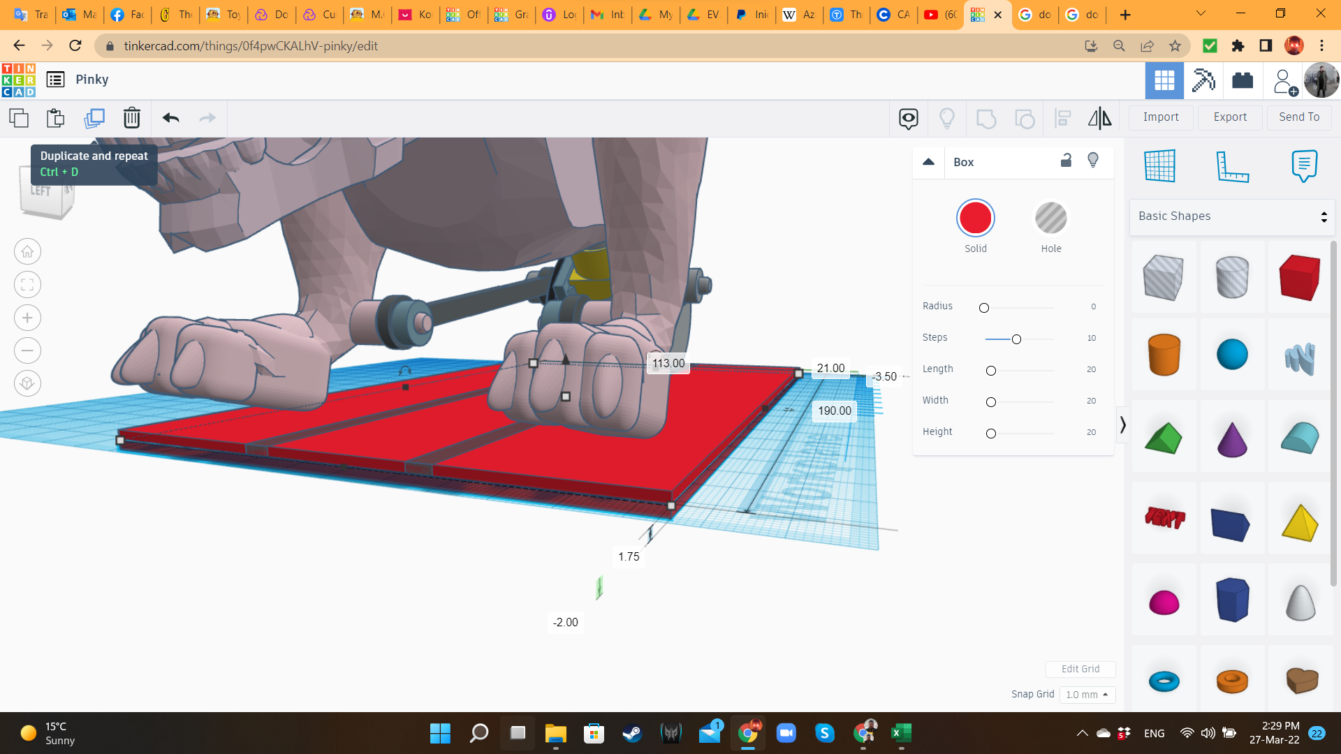
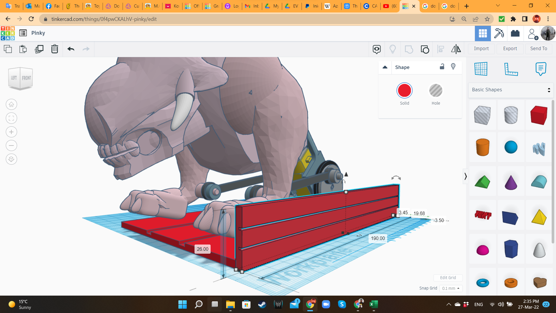
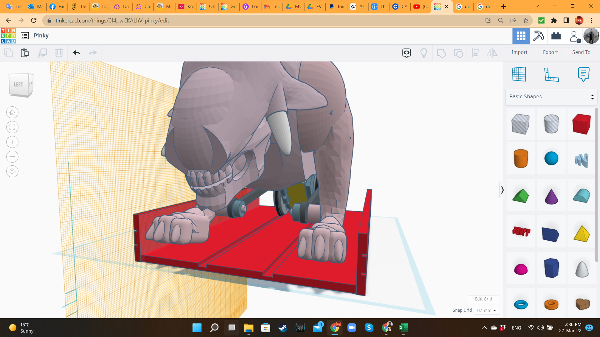
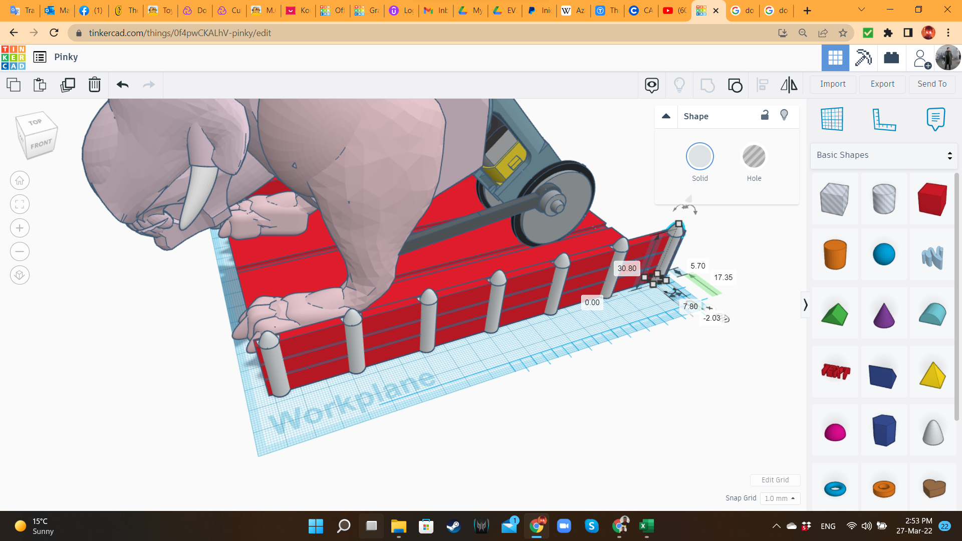
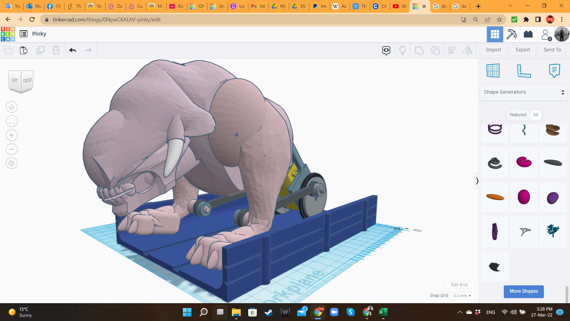
The Battle Beast is ready! Now it's time to create a proper battlefield.
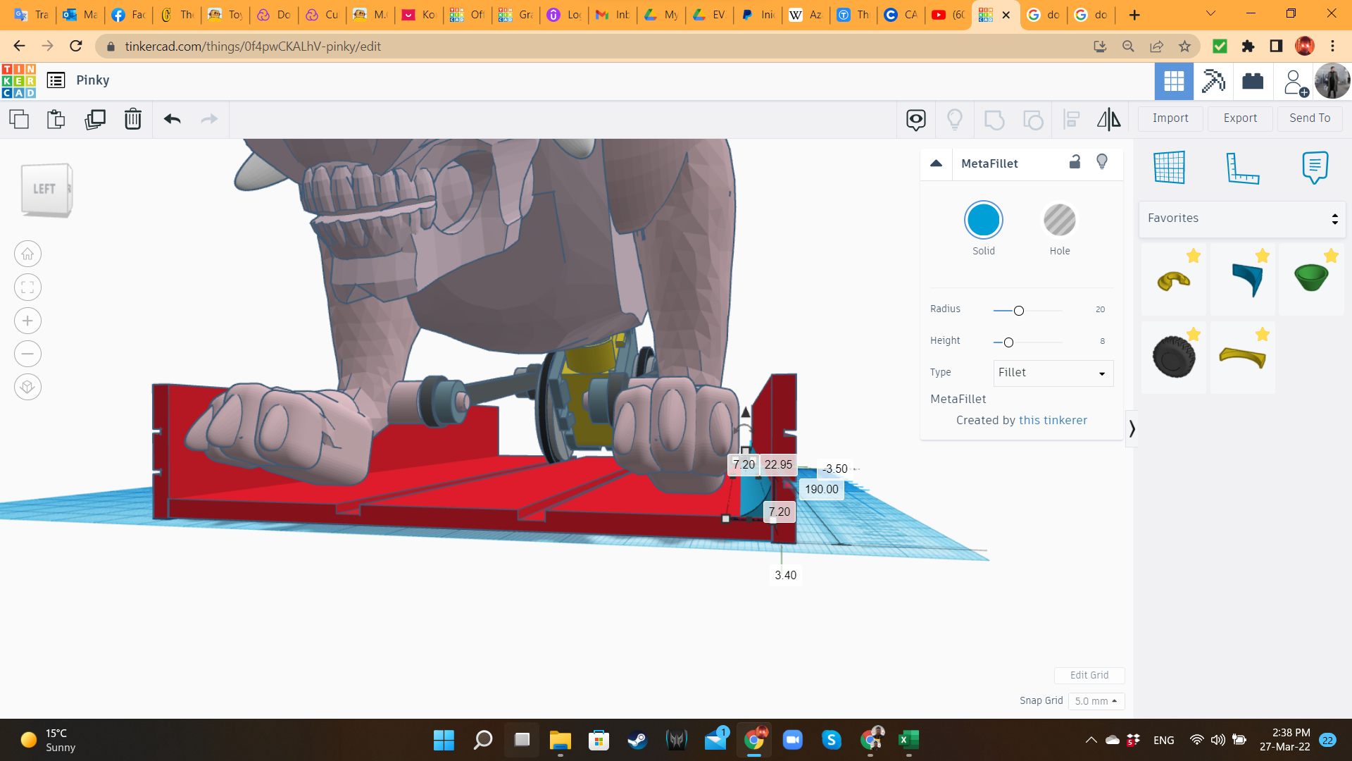
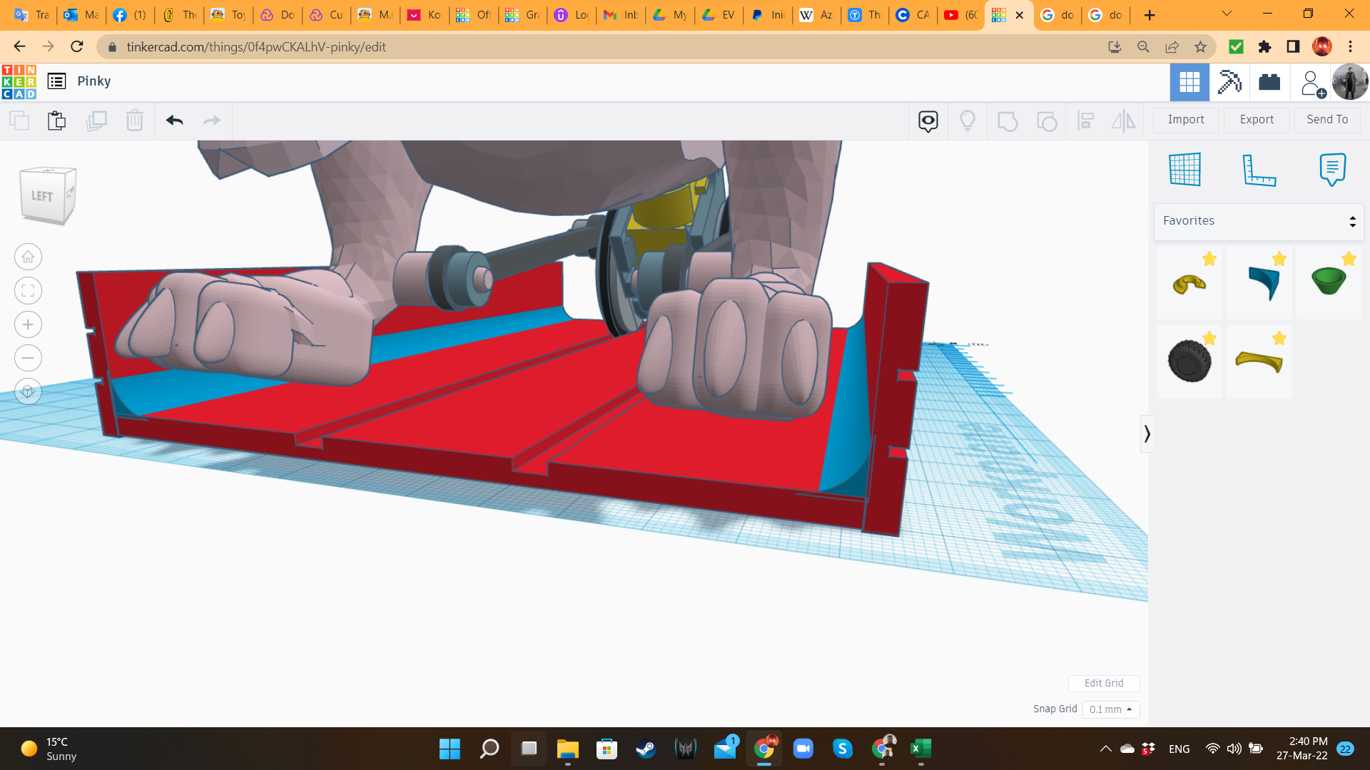
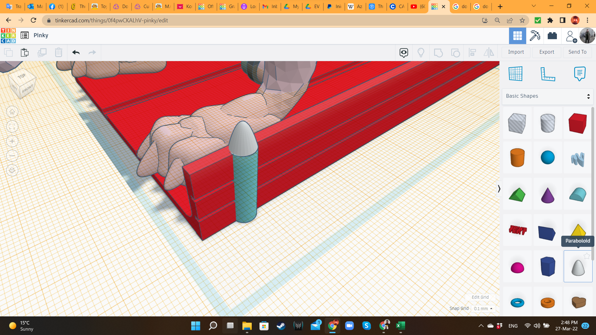
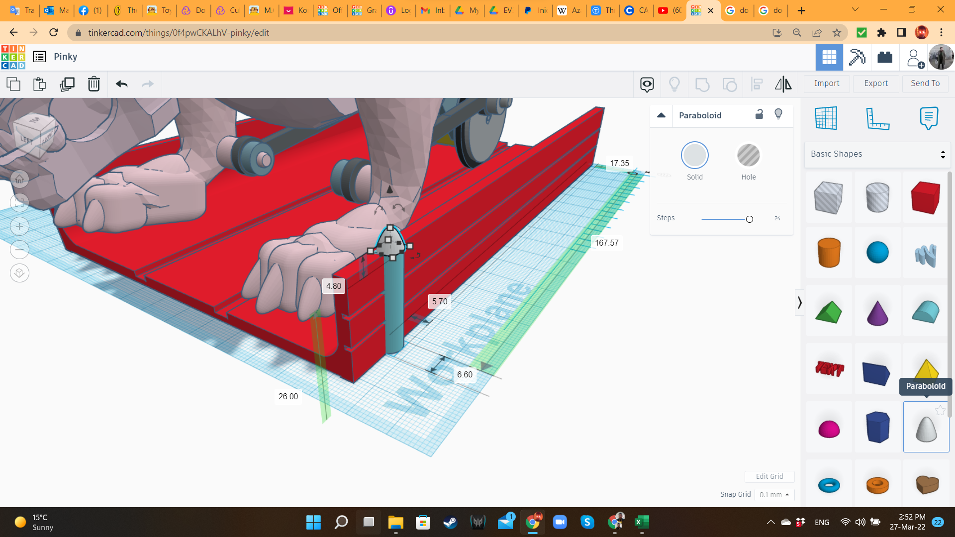
I brought some long hole boxes, and I aligned them to the tires. Then I brought solid boxes to create the platform. I also created some walls, to keep the legs of the creature inside the platform. For a better union between platform and walls, I used MetaFillets and Cylinders as columns.
Battle Track 2: Elevation Bricks
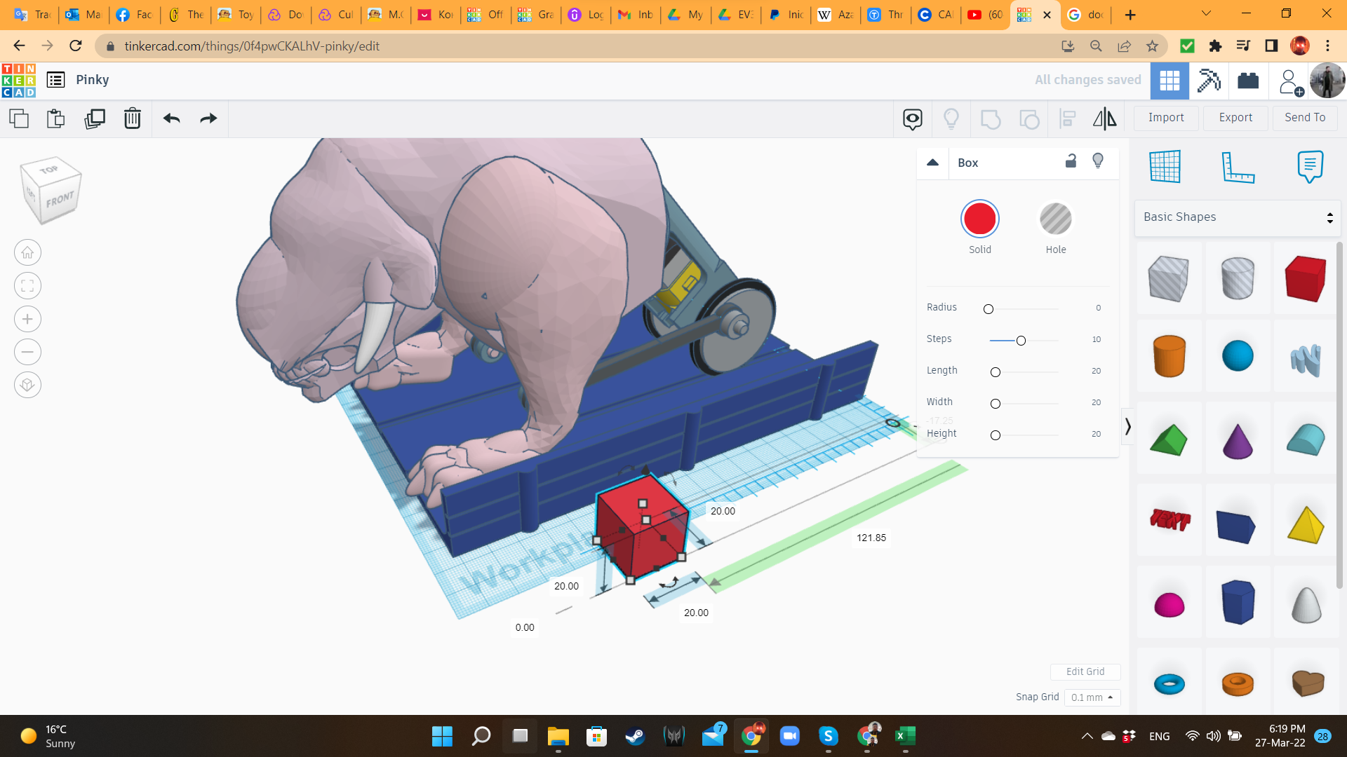
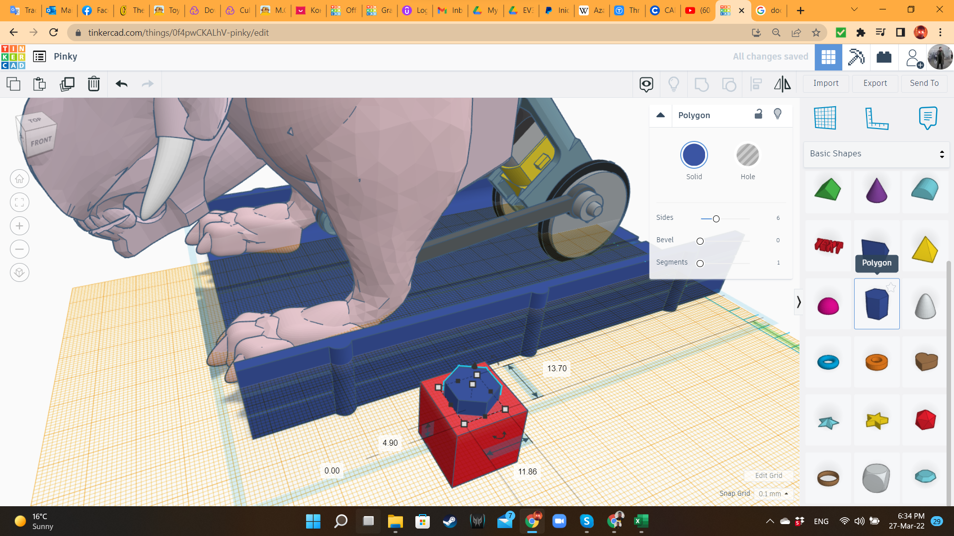
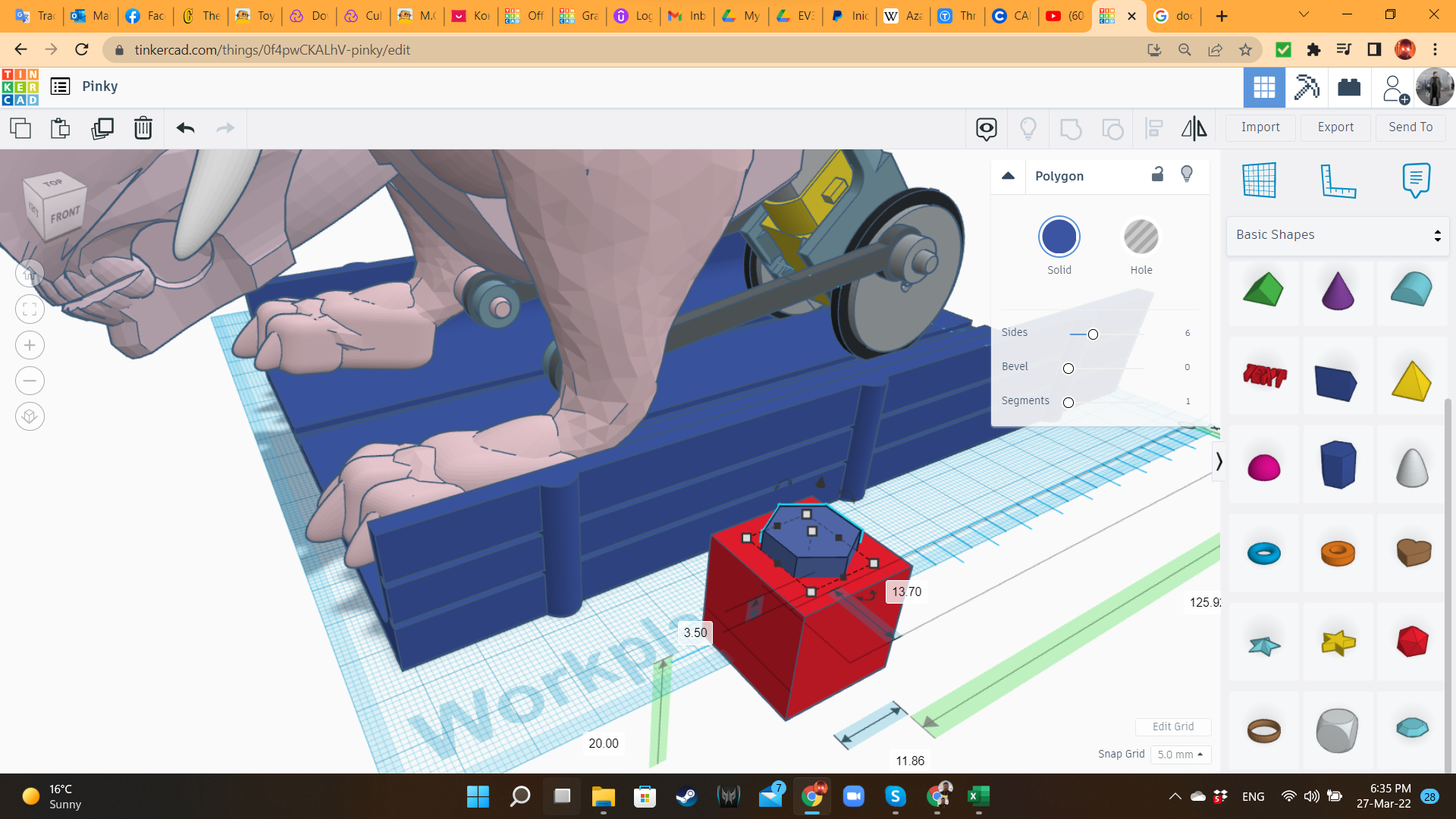
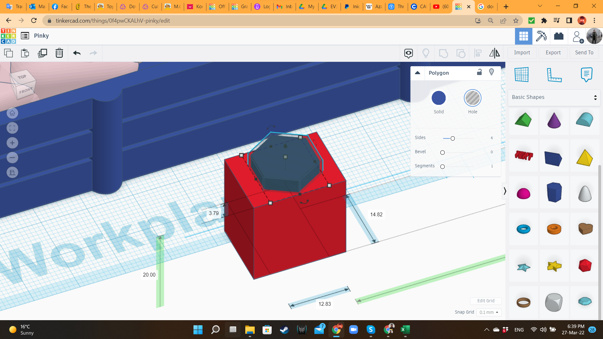
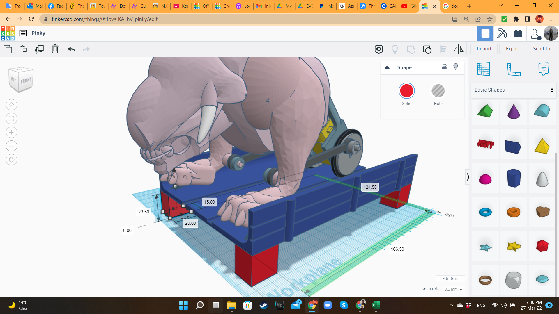
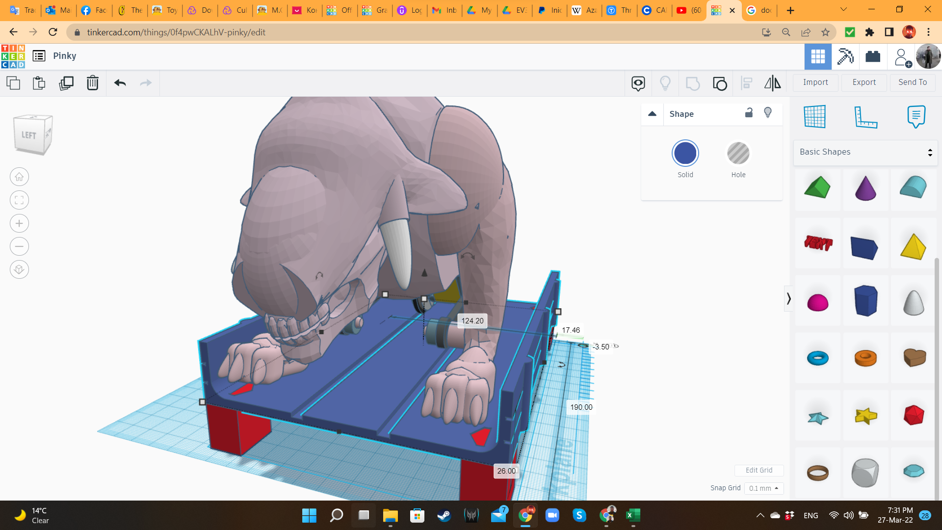
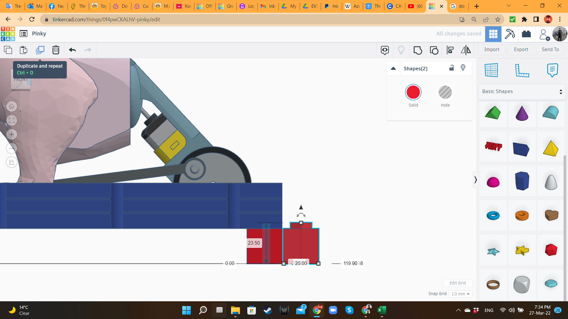
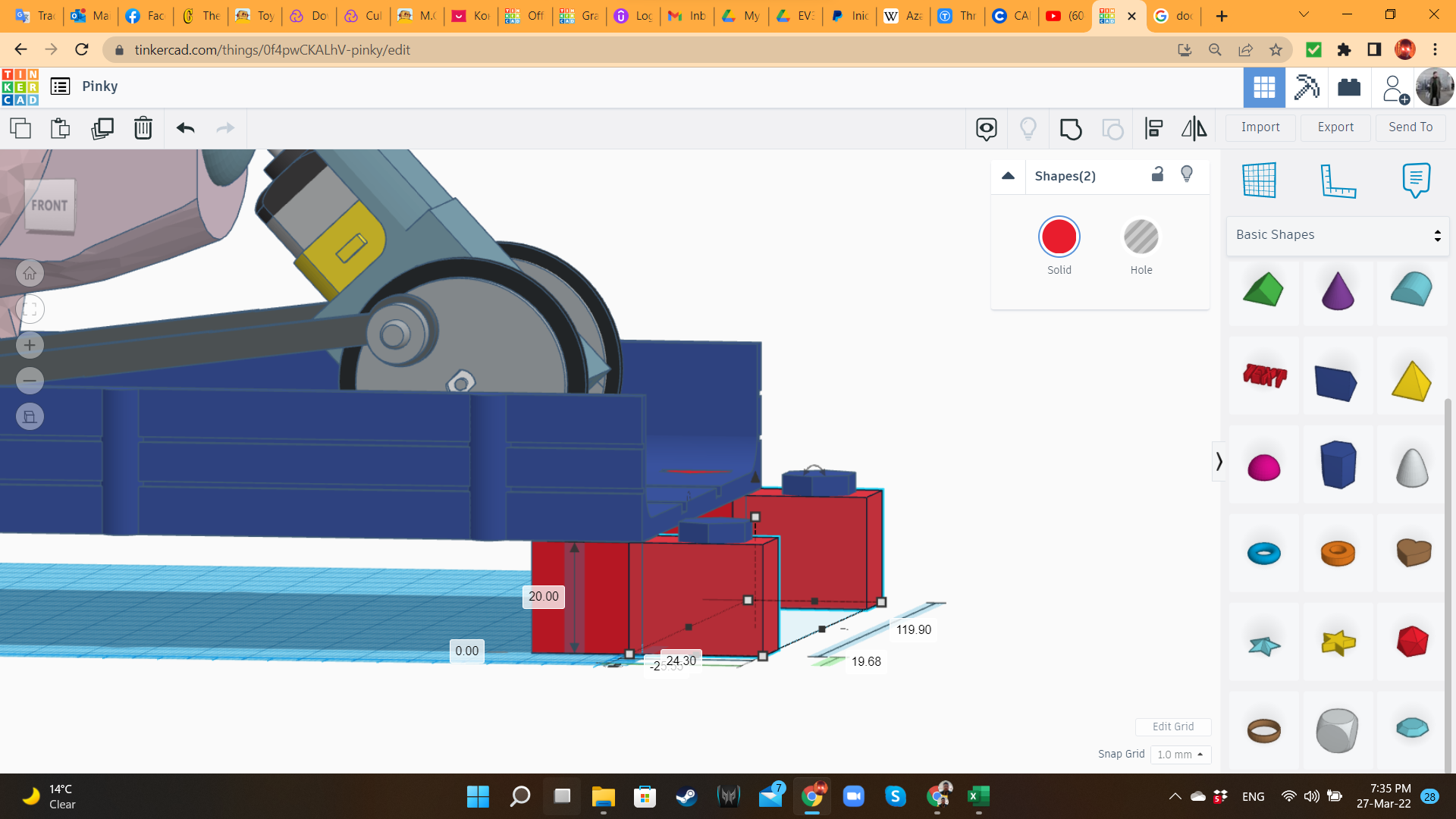
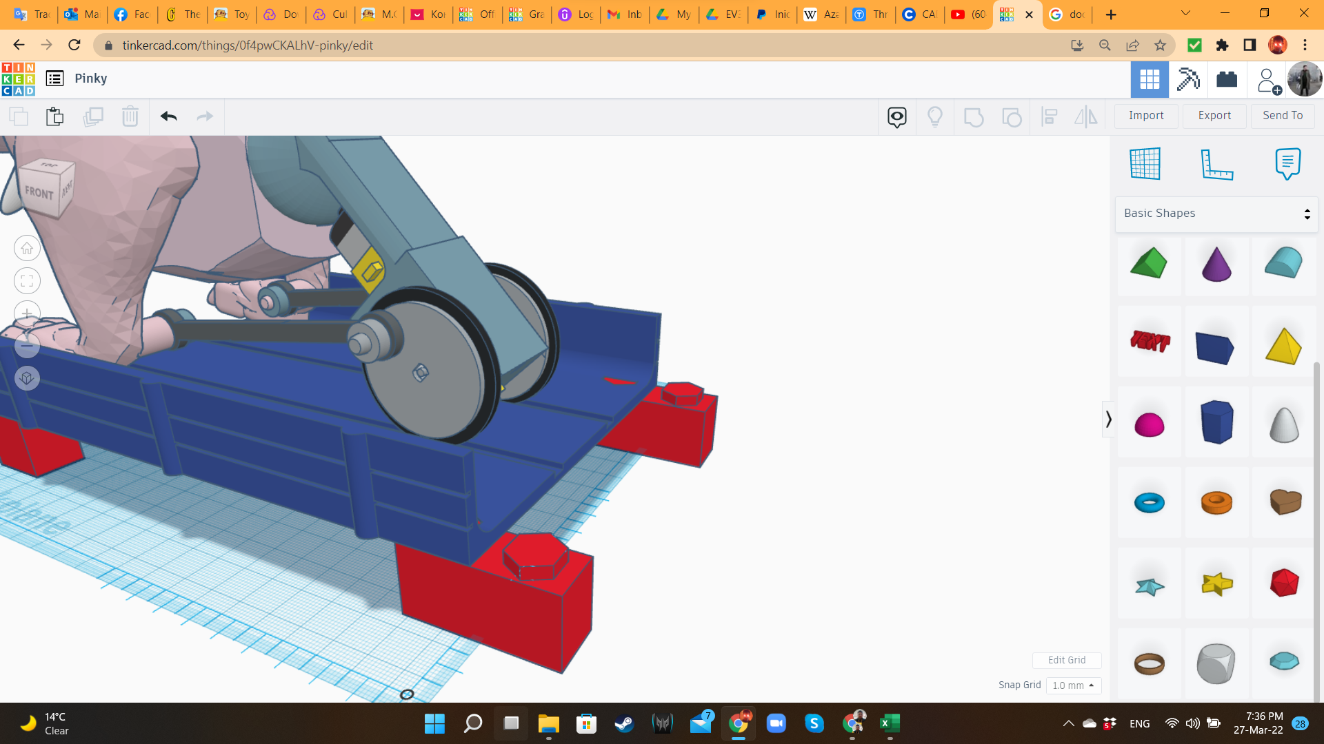
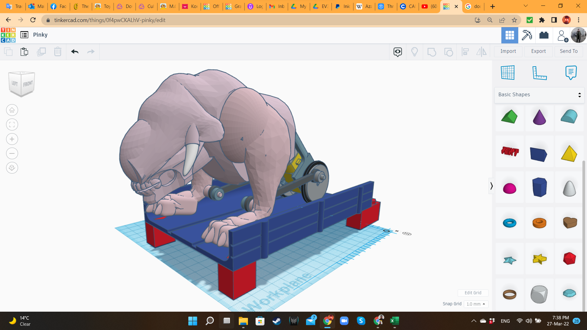
As pillars, I created some "Lego bricks", using Boxes and Polygons from the "Basic Shapes" library. I also created Polygon holes in the four corners of the platform.
For joining one platform to the next one, I also created double bricks. The idea is to print 4 platforms, 4 simple bricks and 6 double bricks.
Slicing
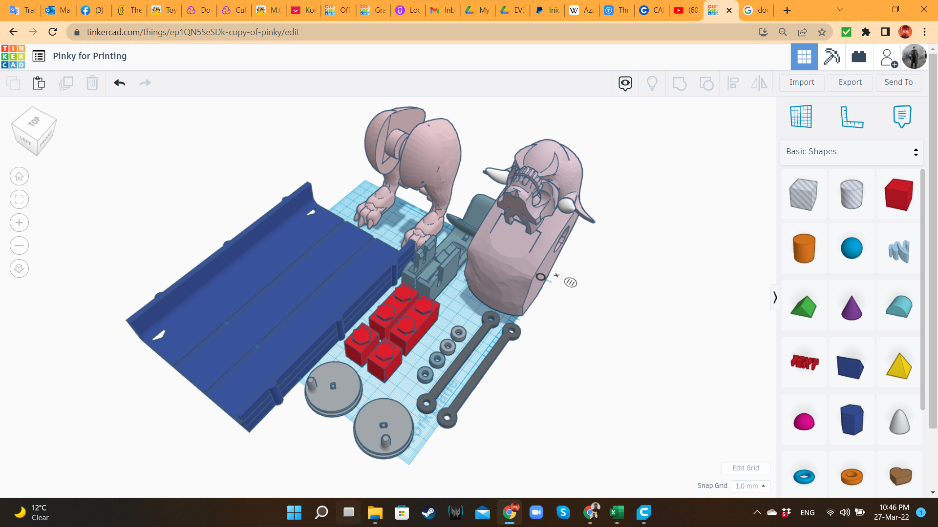
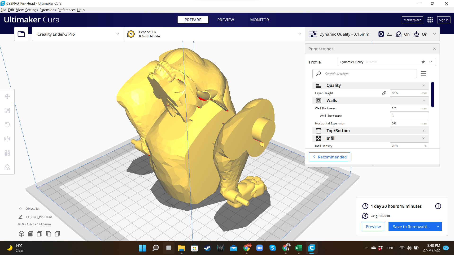
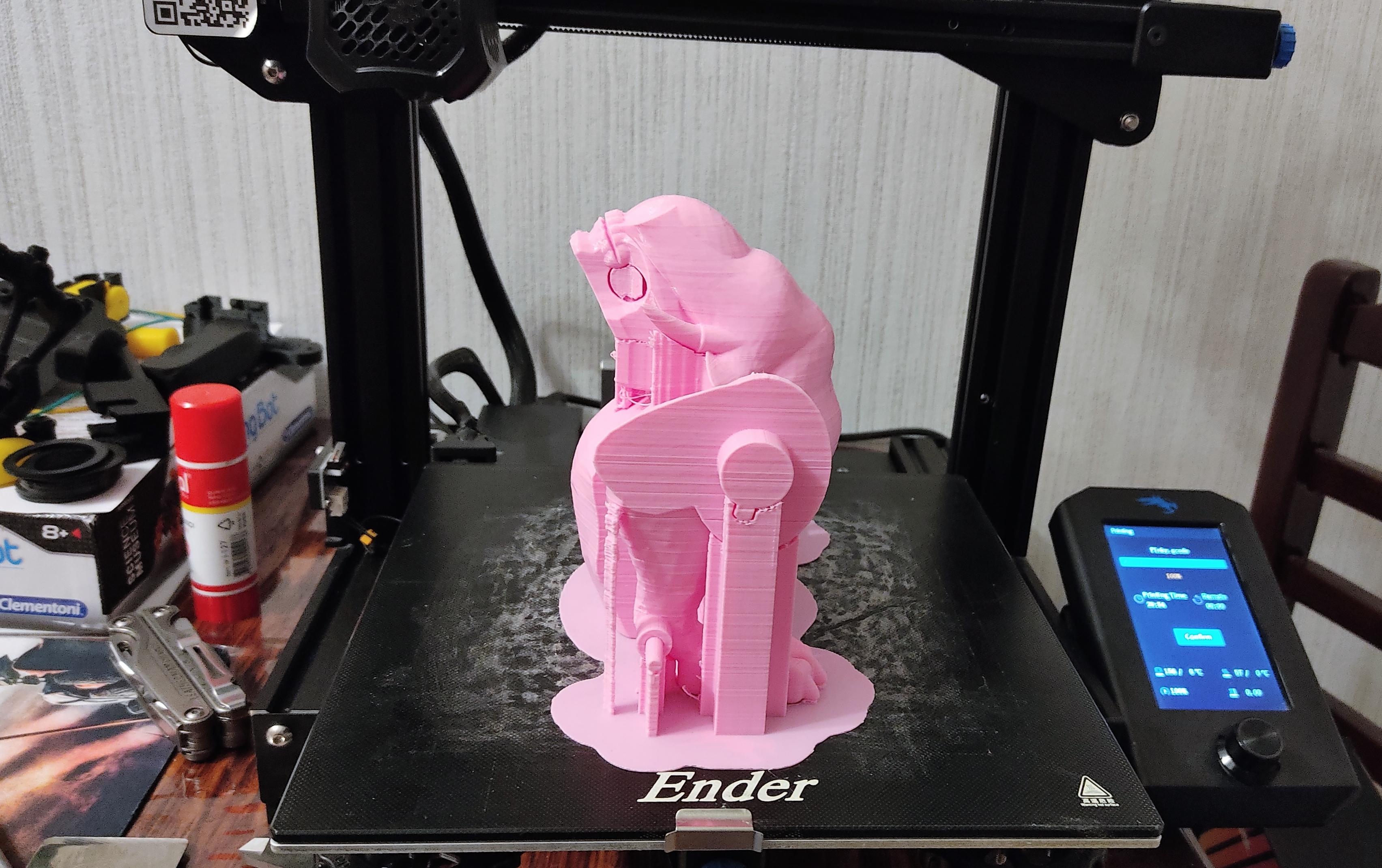
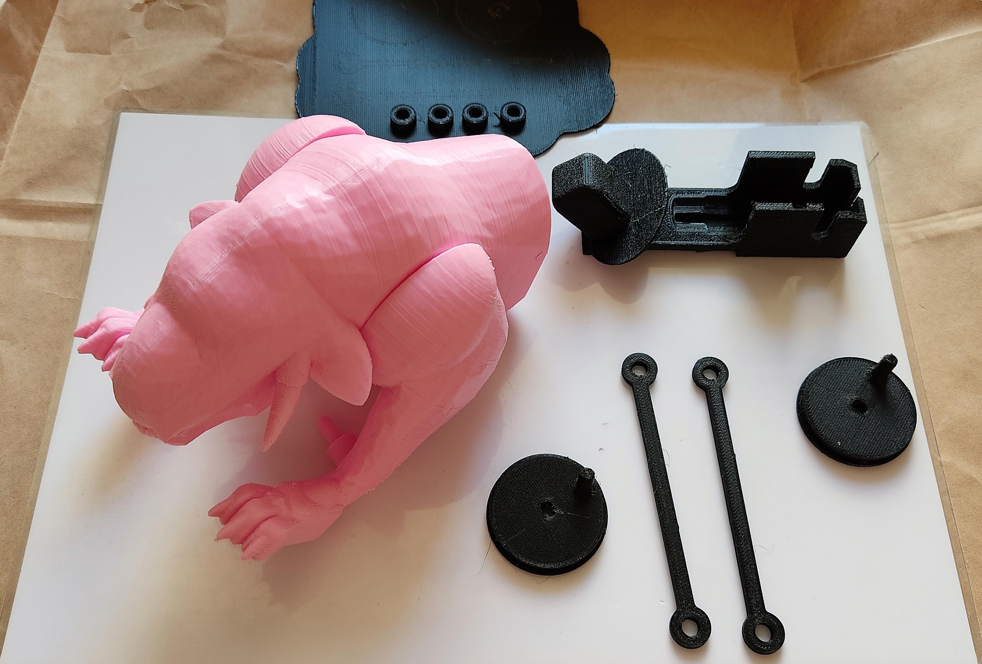
As usual, I created a duplicate of the main design, and placed all the components over the workplane. I also use this copy to quickly correct any mistake I made during the design process.
I exported the STL files of the components, and opened them in the slicer.
I used the following parameters:
- Printer: Creality Ender 3 V2
- Slicer: Ultimaker Cura 4.8.0
- Material: PLA. However, I recommend to use ABS or PETG for the motor base. If that's not possible, then use PLA, but be very careful when inserting the motor.
- Printing Temperature: 200°C
- Infill: 20% (head/body, platforms and bricks), 100% (motor case, washers, rods), 30% (wheels)
- Walls (shell): 4
- Supports: Linear
- Raft: yes (I love Raft).
- Scale: 100%
Painting
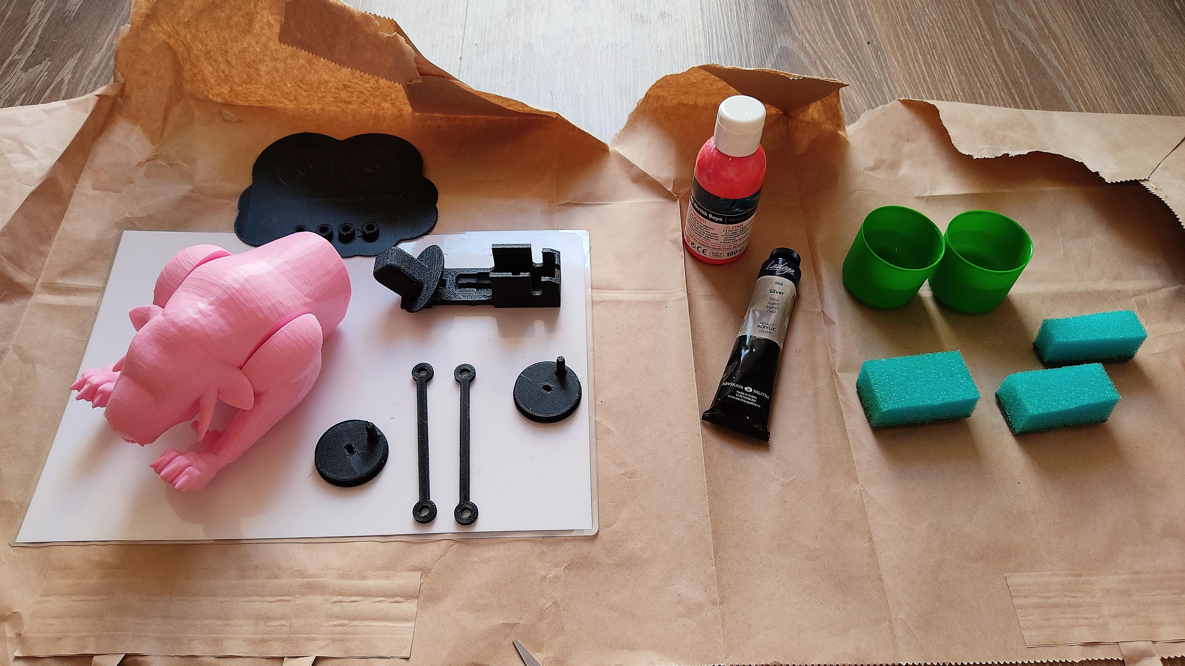
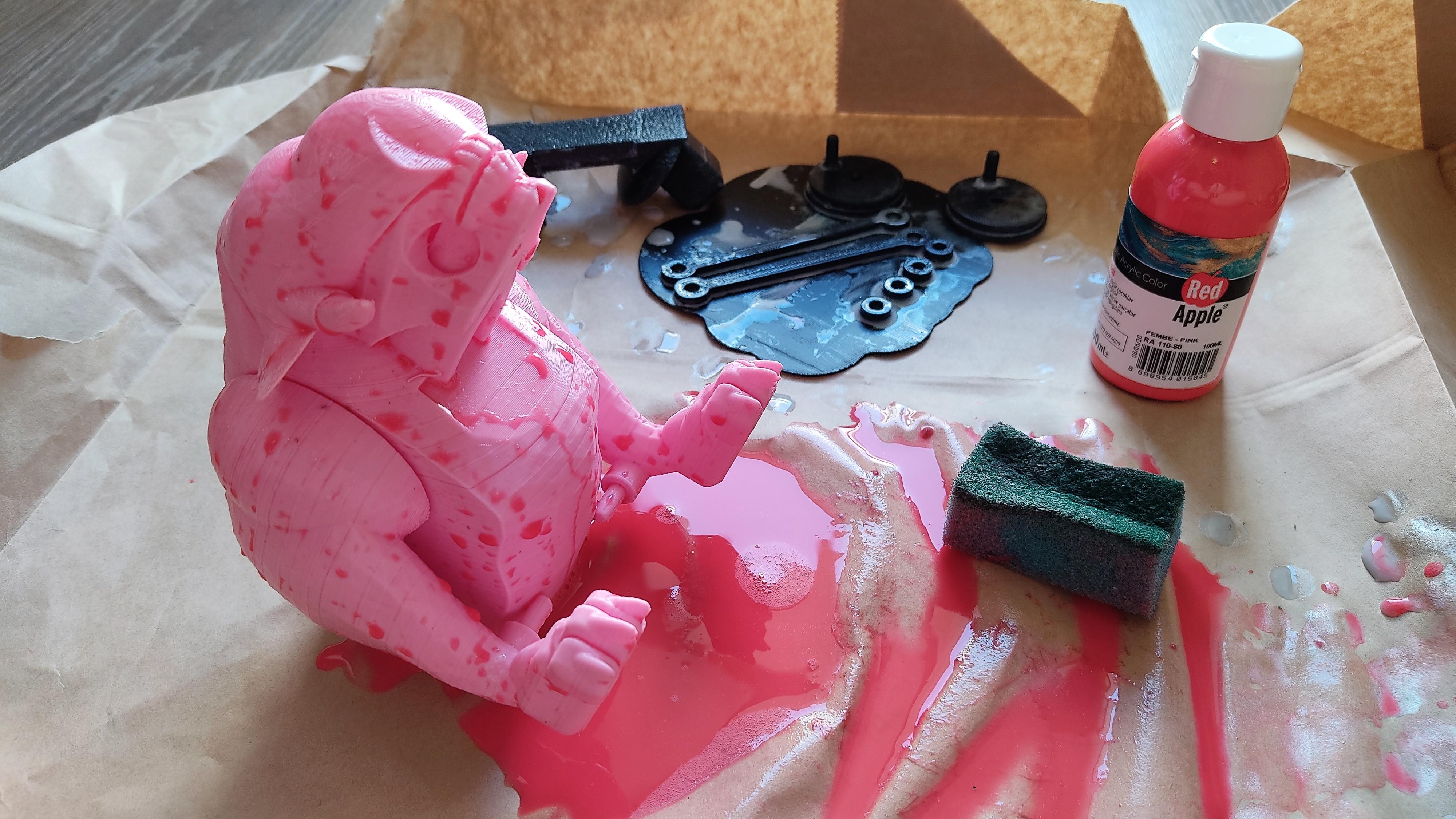
I got some pink, white and silver acrylic painting, so I proceeded to give a quick paint job to Pinky. First I tried with a sponge, water and paint. Then, I used a brush, and applied the paint directly to the model.
Probably you will have more time to paint it with more detail, but be very careful with the mechanical parts, to avoid potential jammings.
Assembling the Motor Case
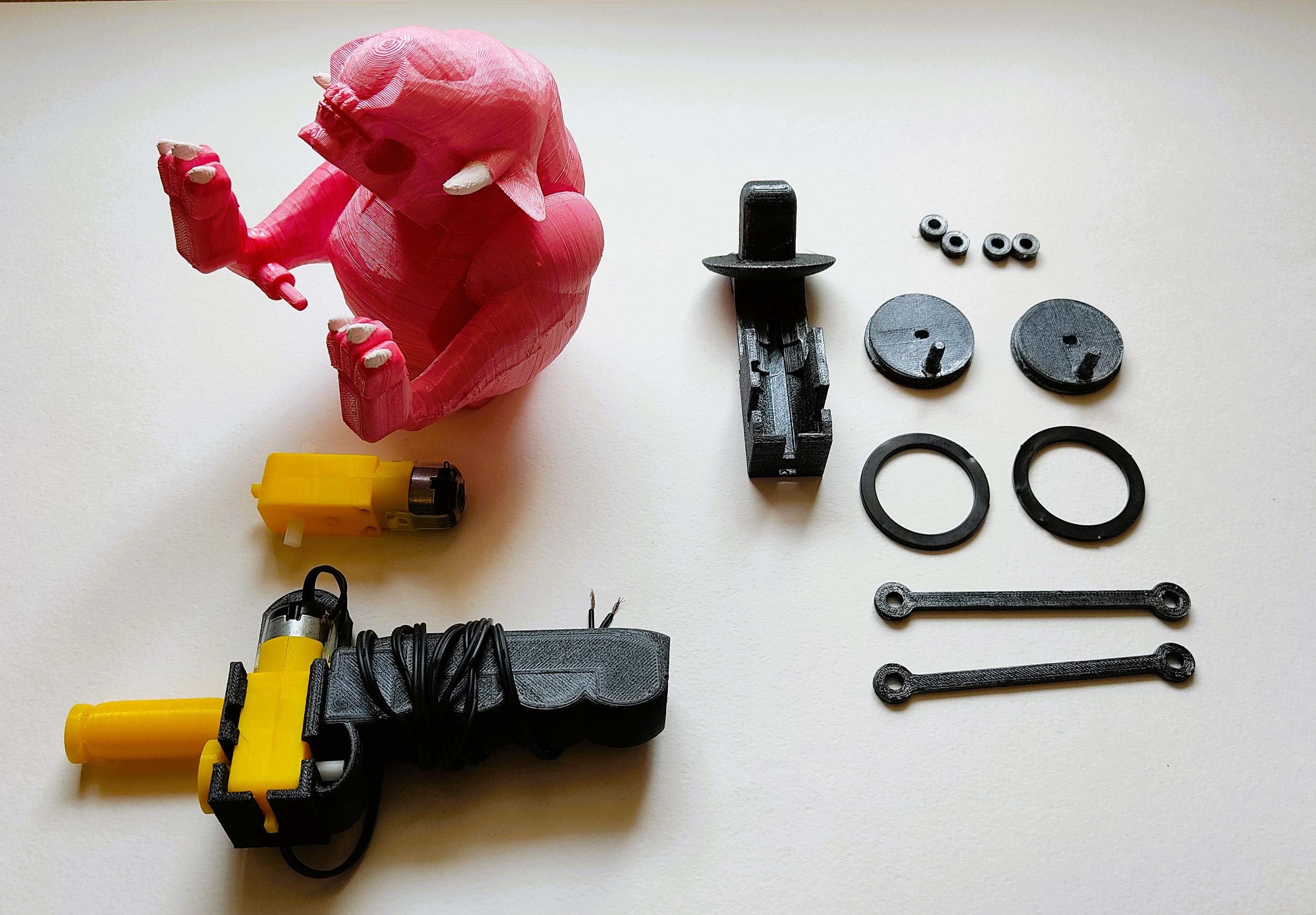
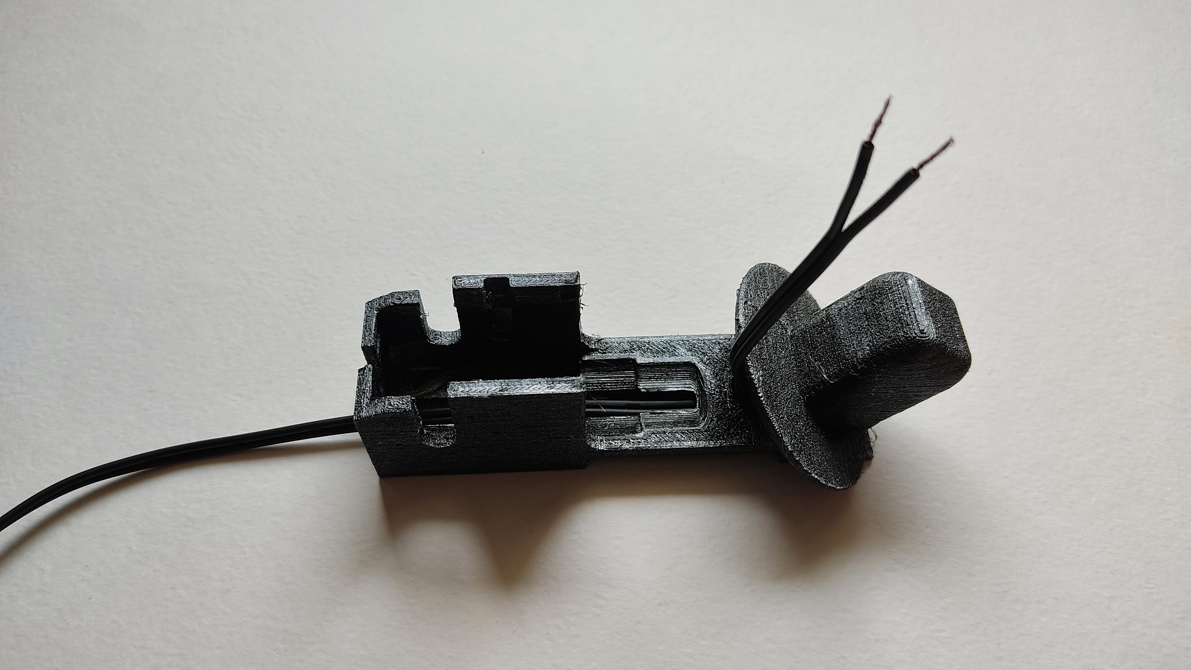
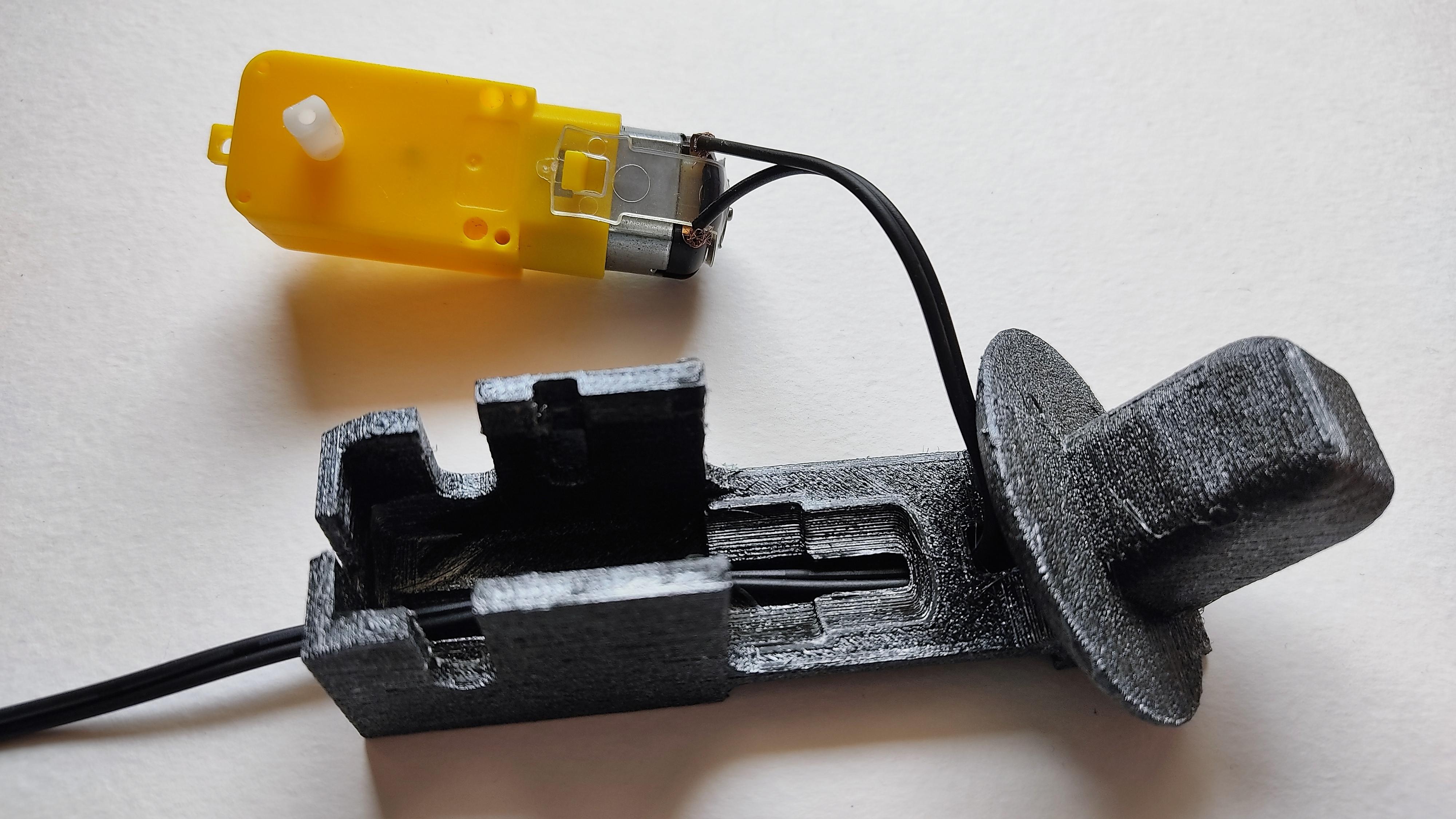
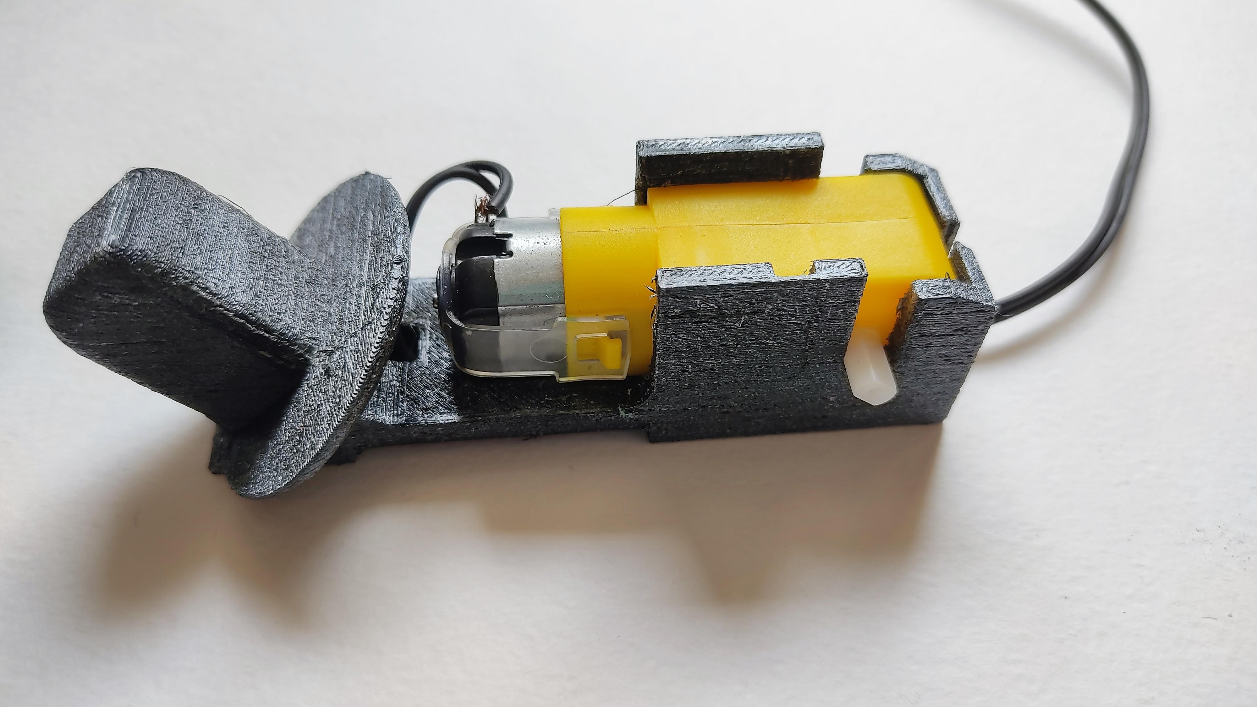
After painting the parts, I brought them over the table. The motor part must be assembled in the same way of the first Hand Dynamo, inserting the cable through the tunnel, and placing the gearbox in a very careful way. Don't forget to connect the wires to the motor. Remember that the cable we are connecting is the available end of the cable that is already connected to the Hand Dynamo. Don't forget to check the right polarity: when you rotate the crank to the front, the wheels must also rotate to the front, and vise-versa.
Attaching the Wheels
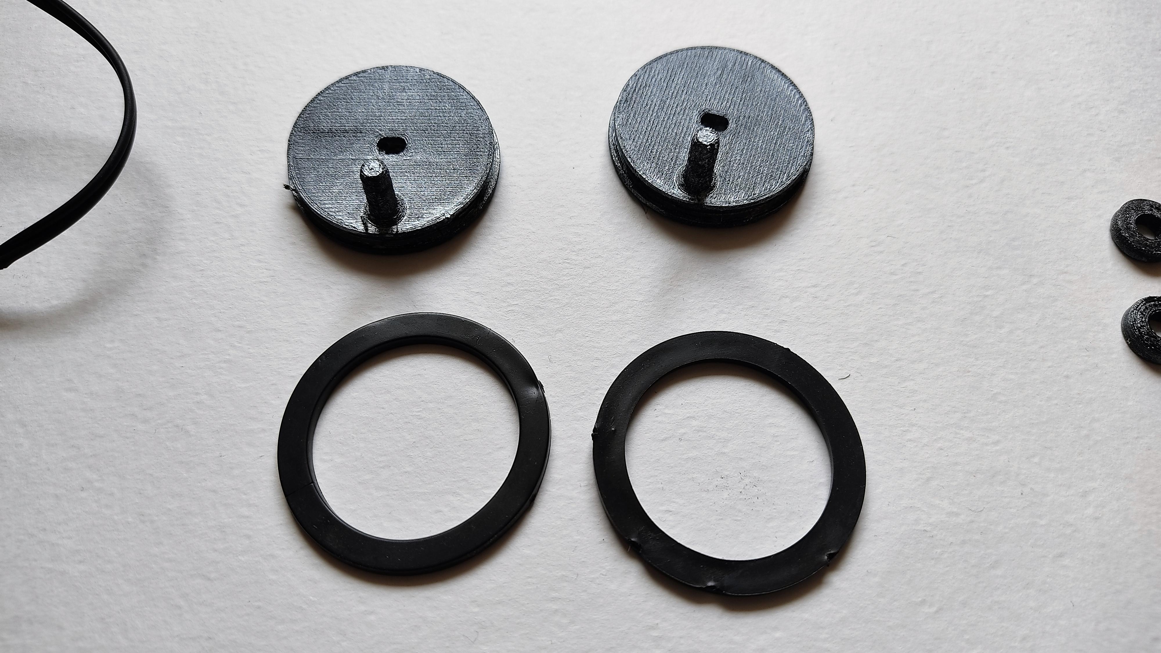
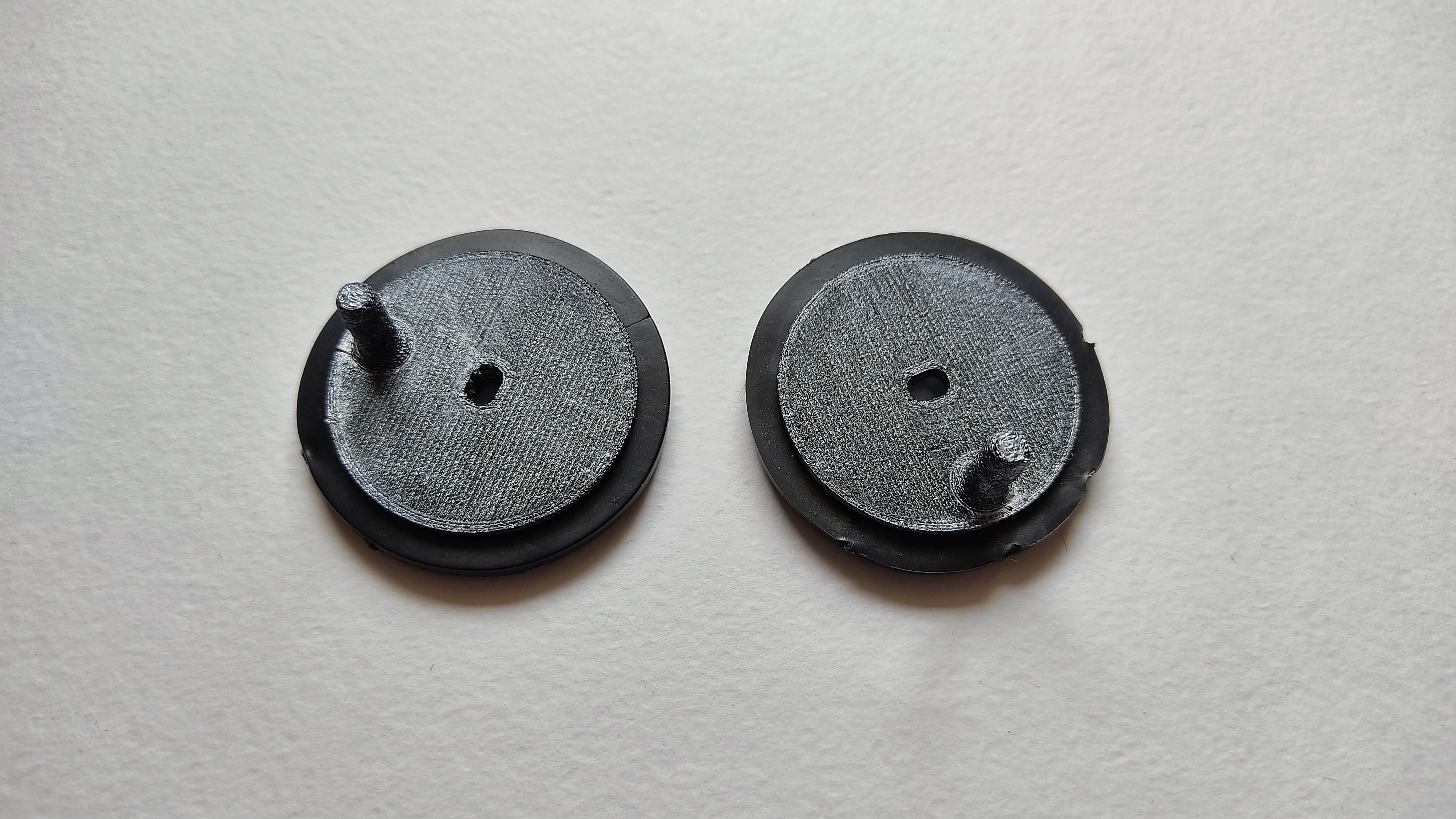
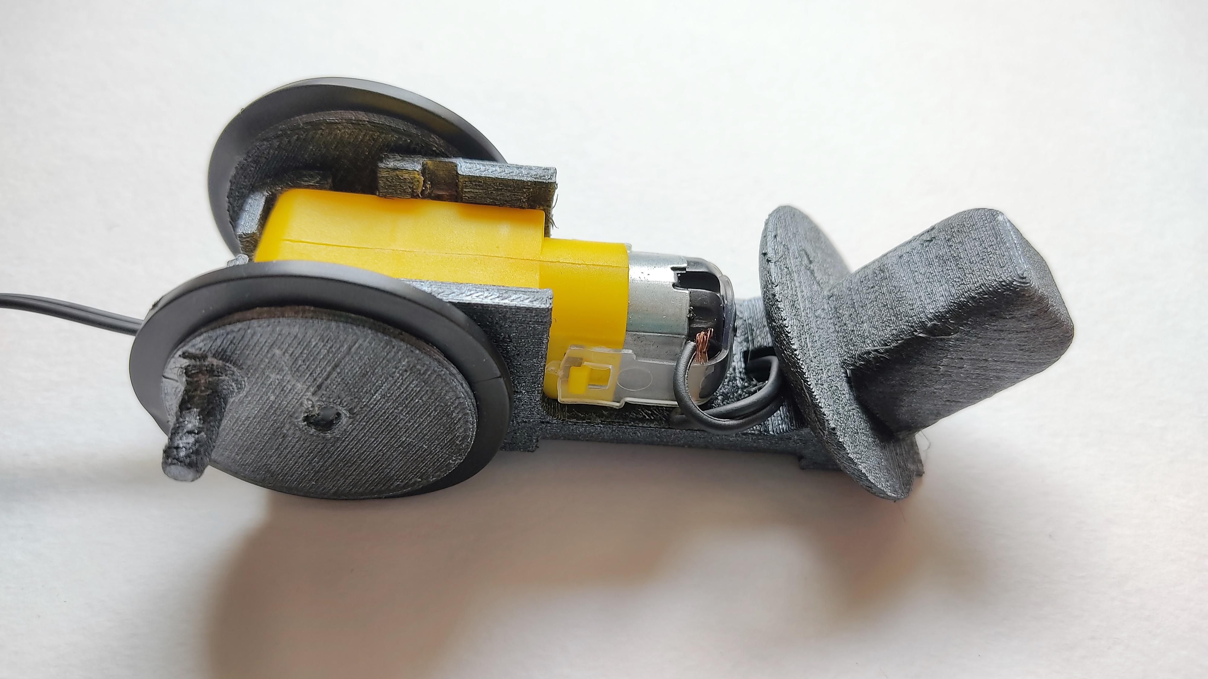
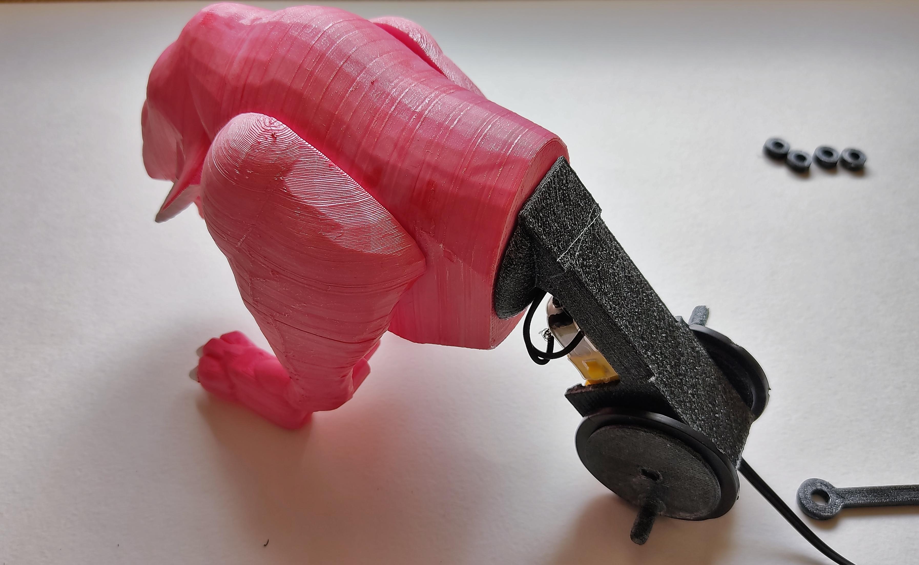
Add the rubber rings to the wheels. Then, attach them to the motor case.
At the end, insert the motor case into the rear part of the organic body.
Adding the Rods
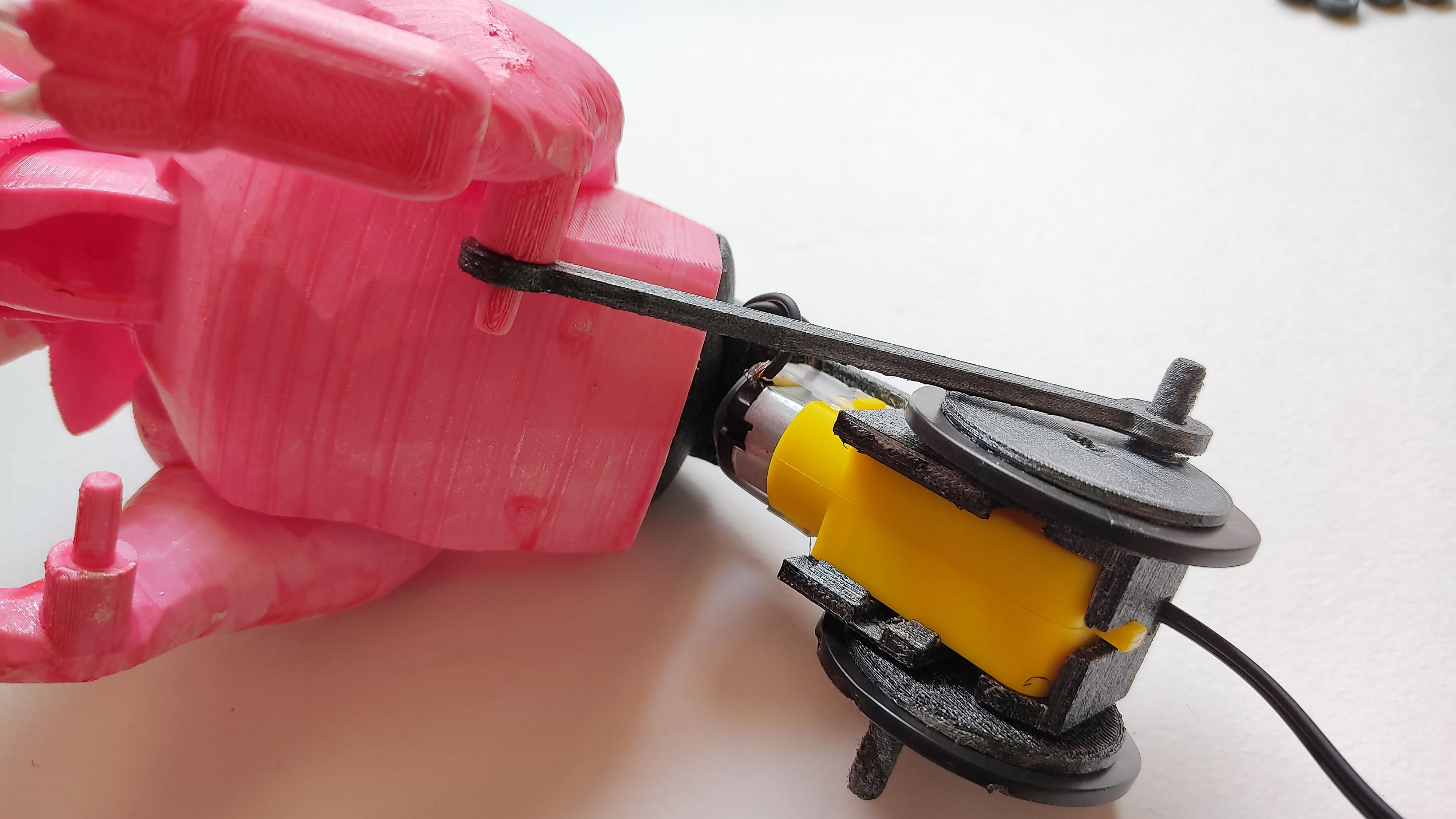
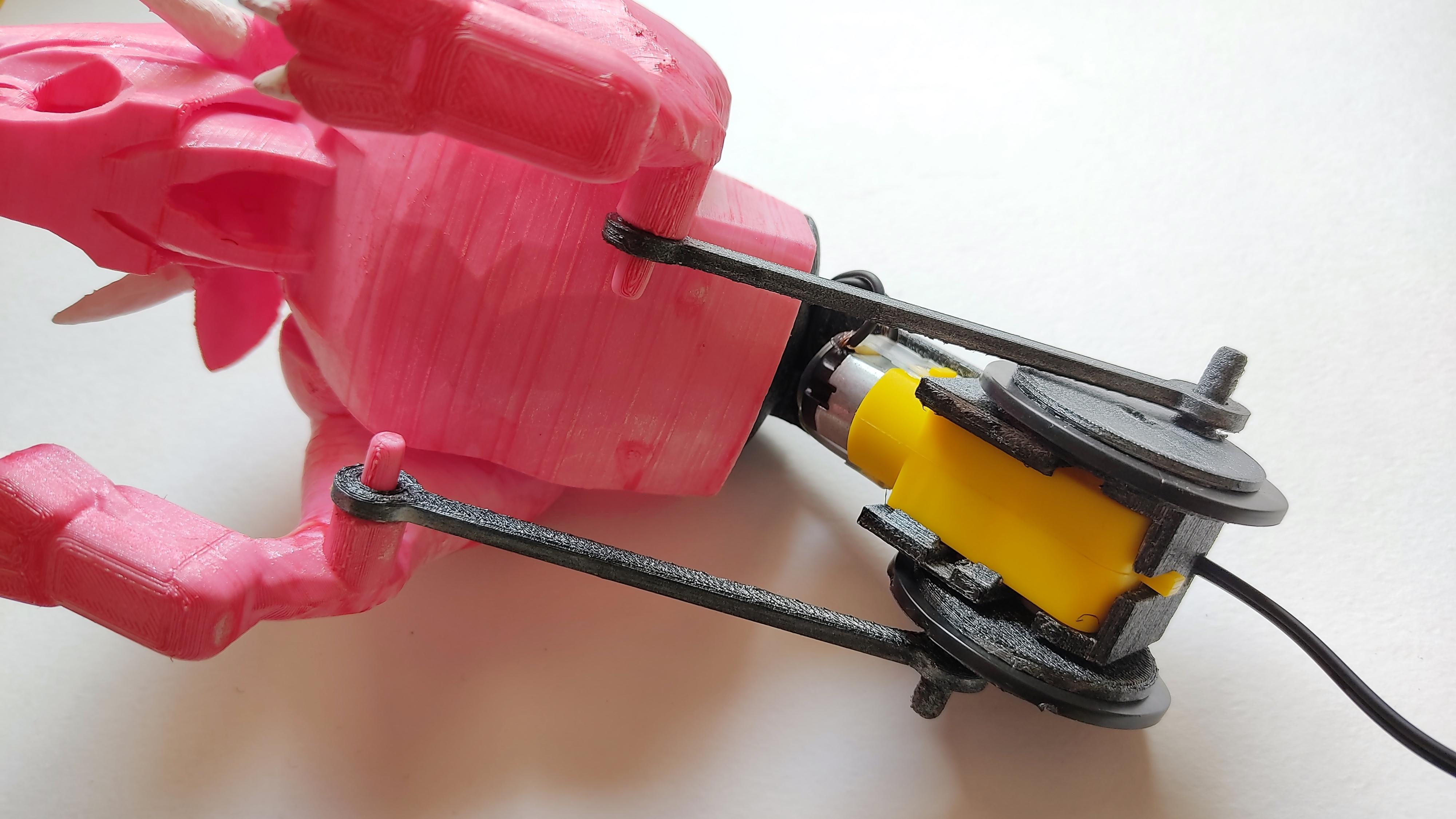
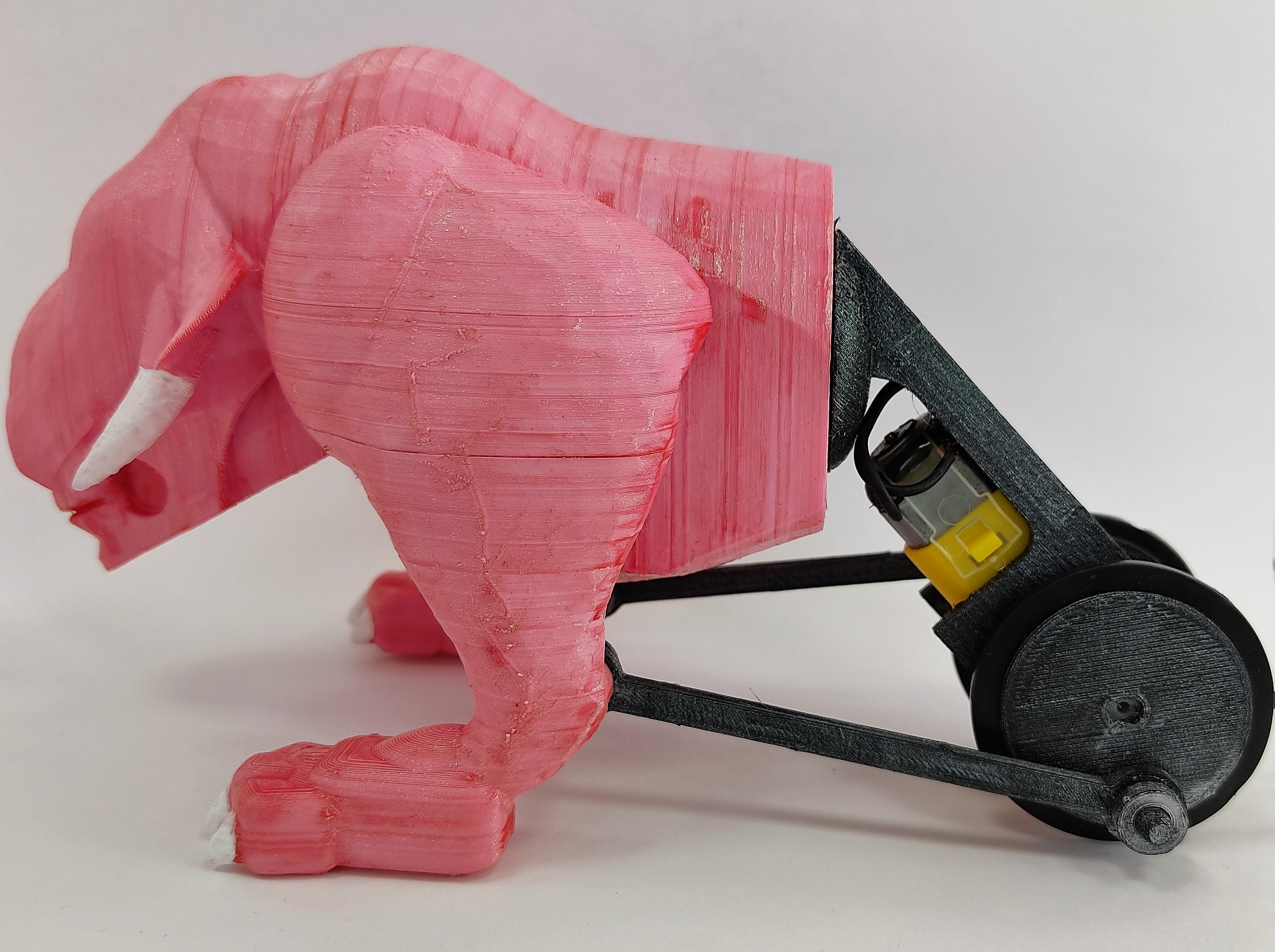
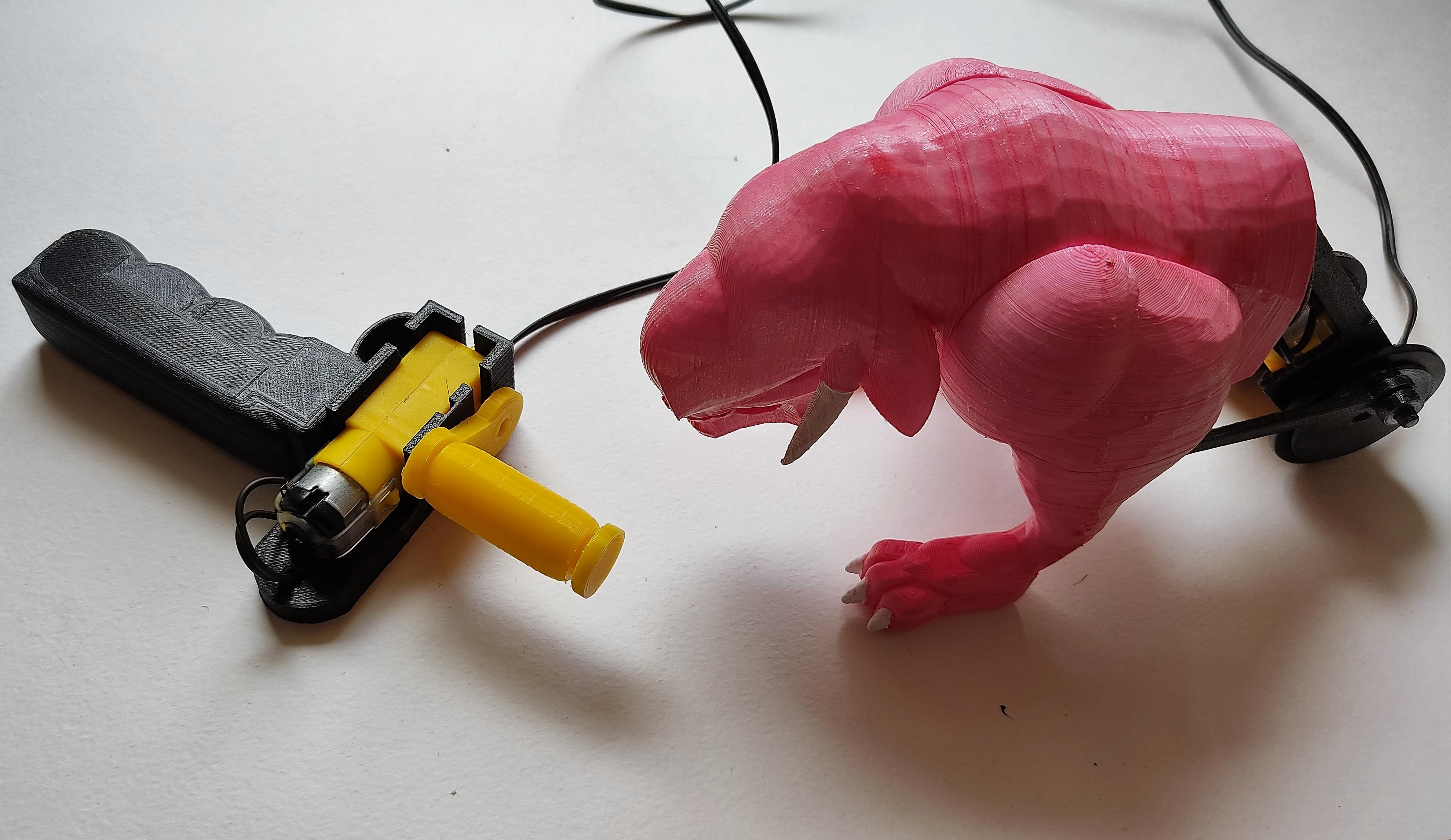
Place each rod, with one end inserted into the wheel/crank, and the other end inserted into the small cylinder at the foot. Then, fasten the rods using the washers. Pinky is ready for action!
Building the Battle Track
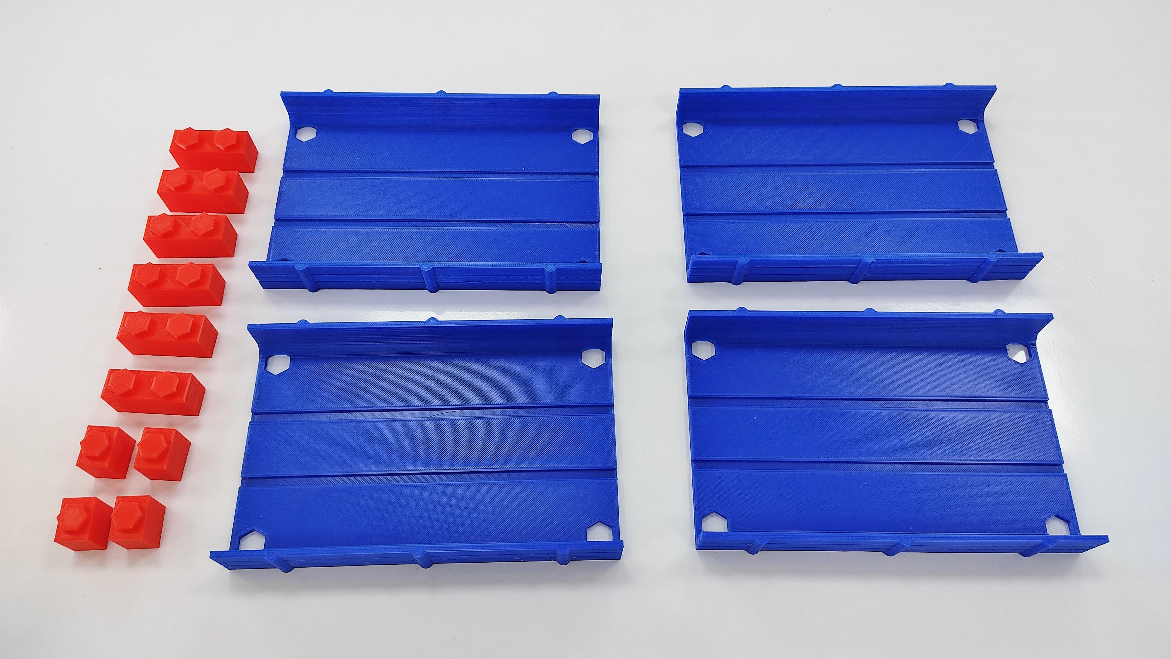
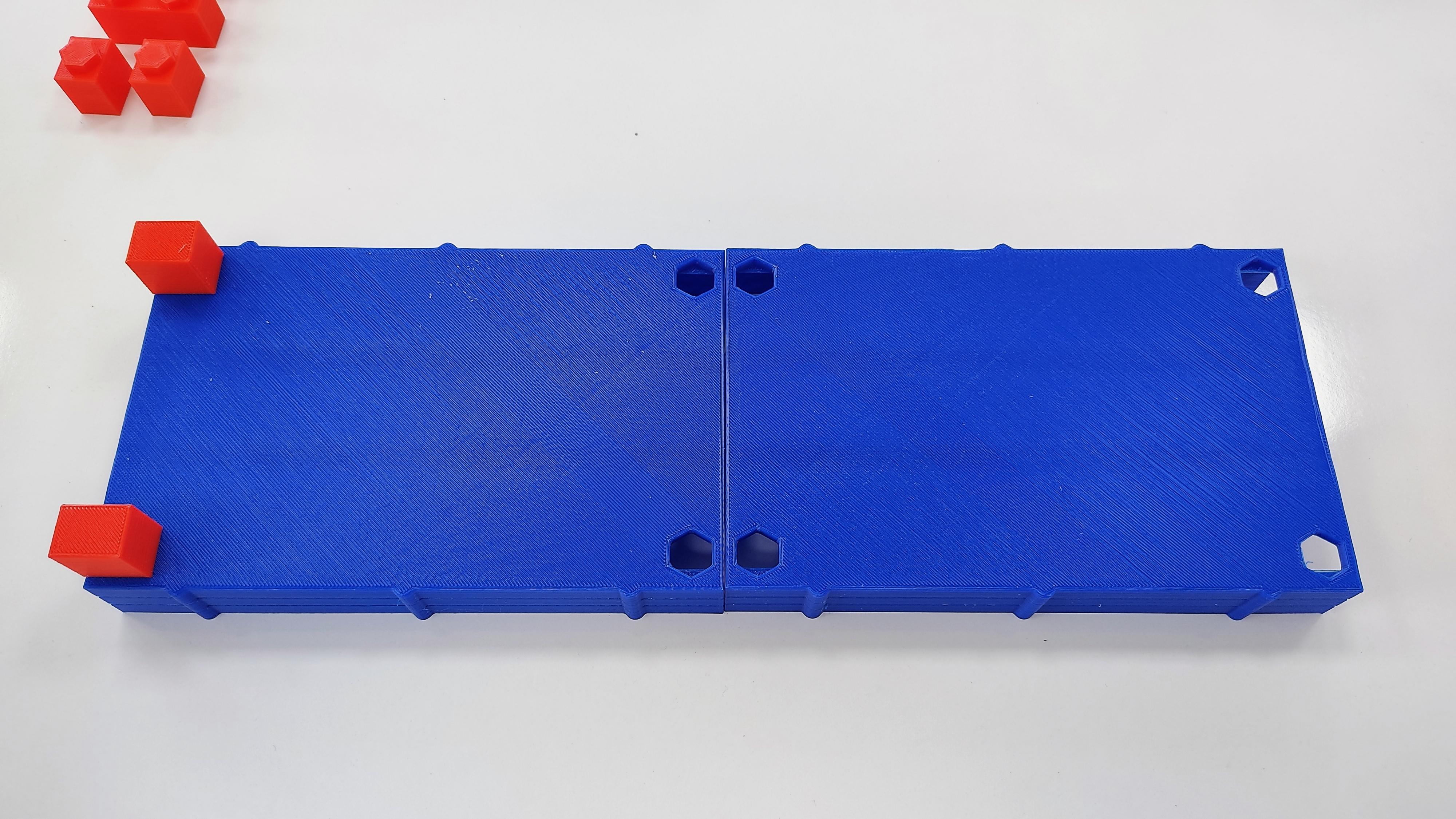
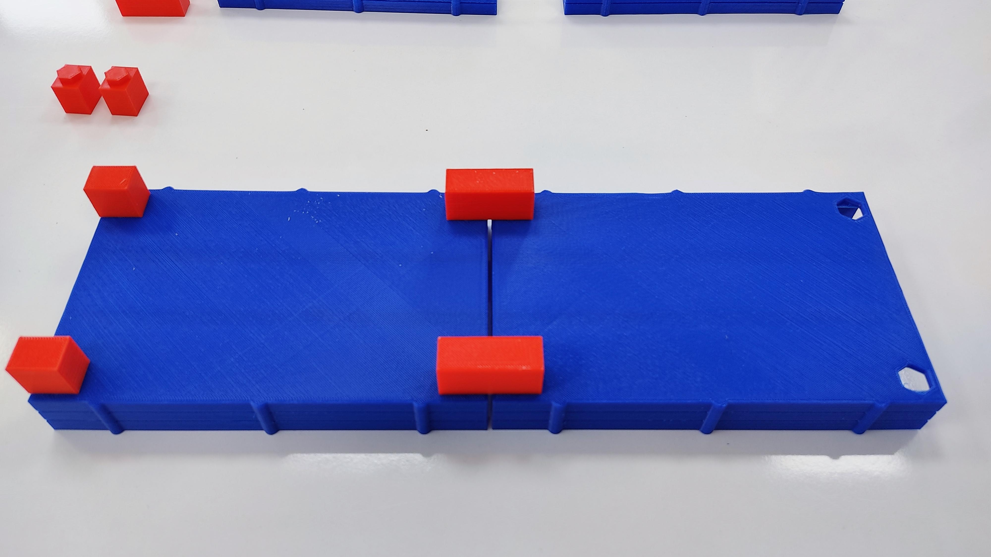
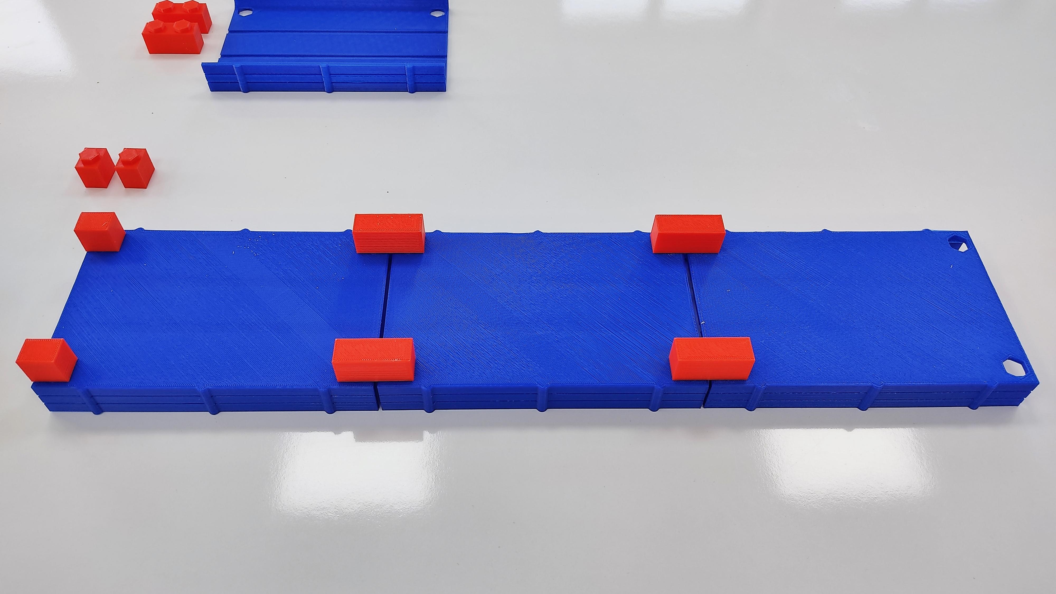
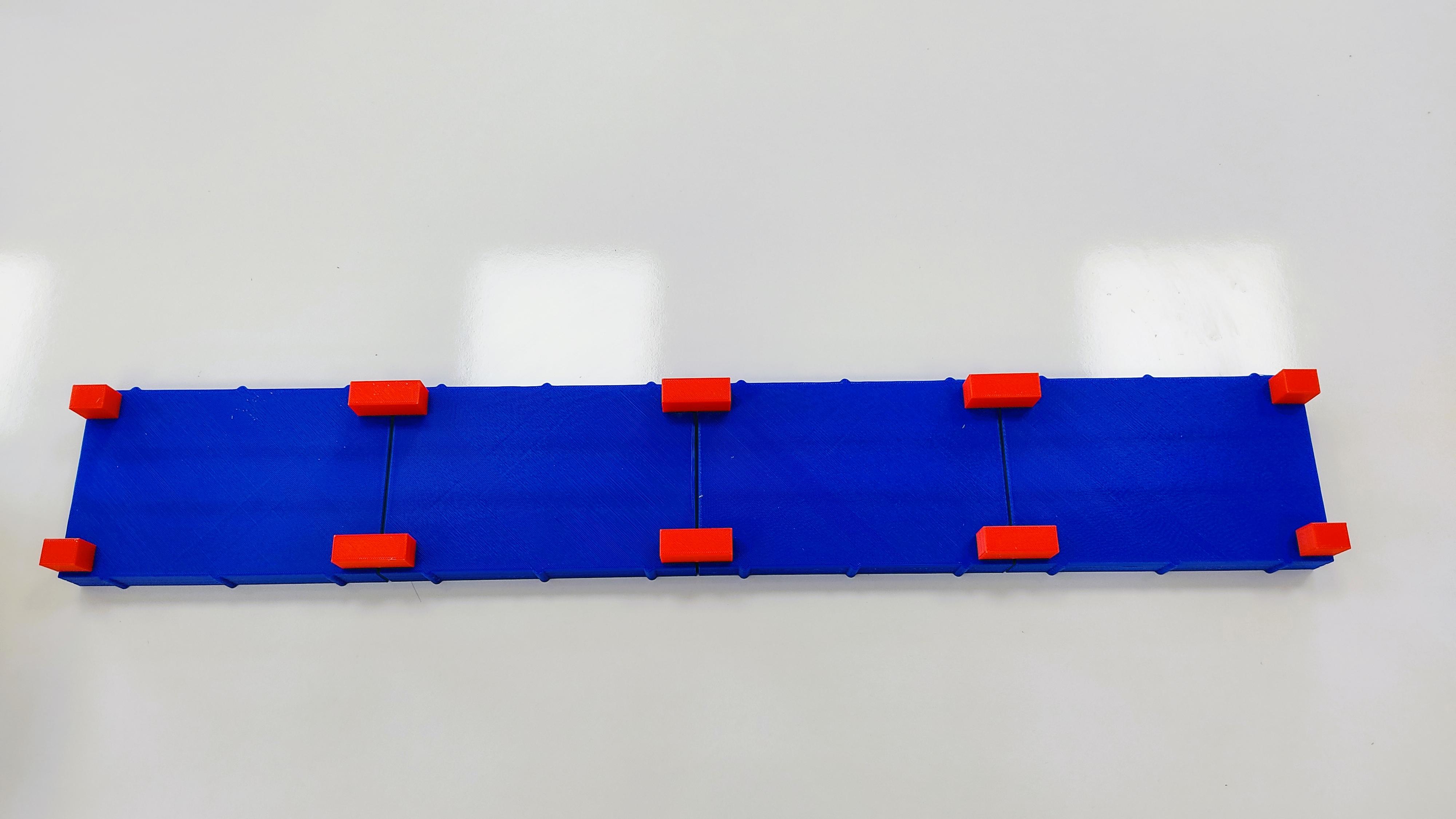
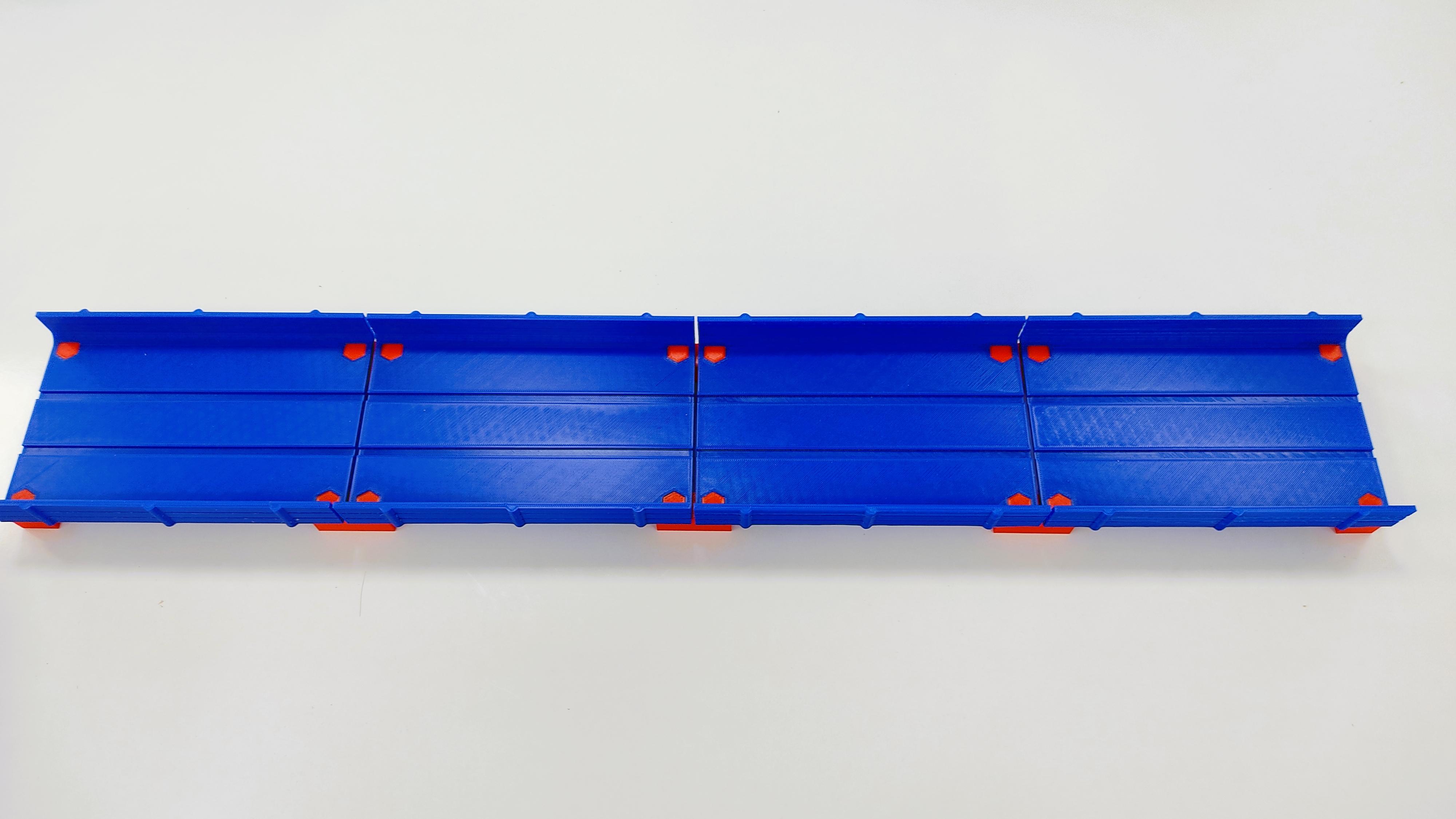
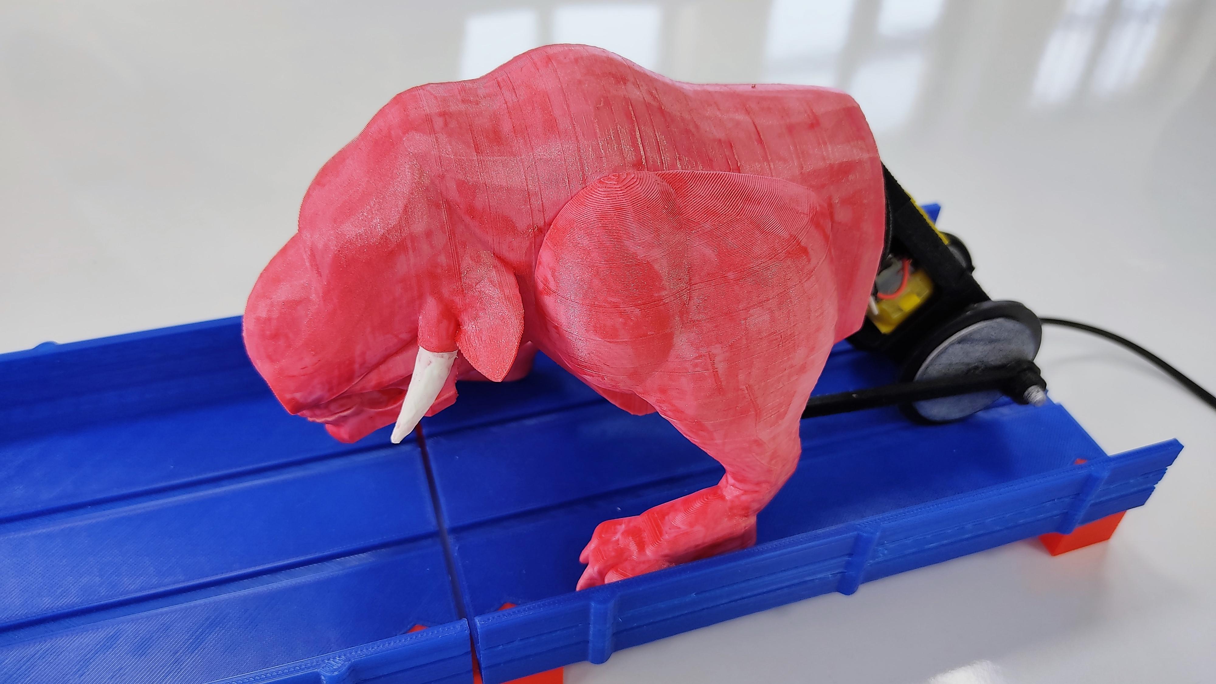
Take the platforms. Place the simple bricks at the starting point of the platform, and the double bricks in the union points between one platform and the other.
LET THE BEAST BATTLES BEGIN!
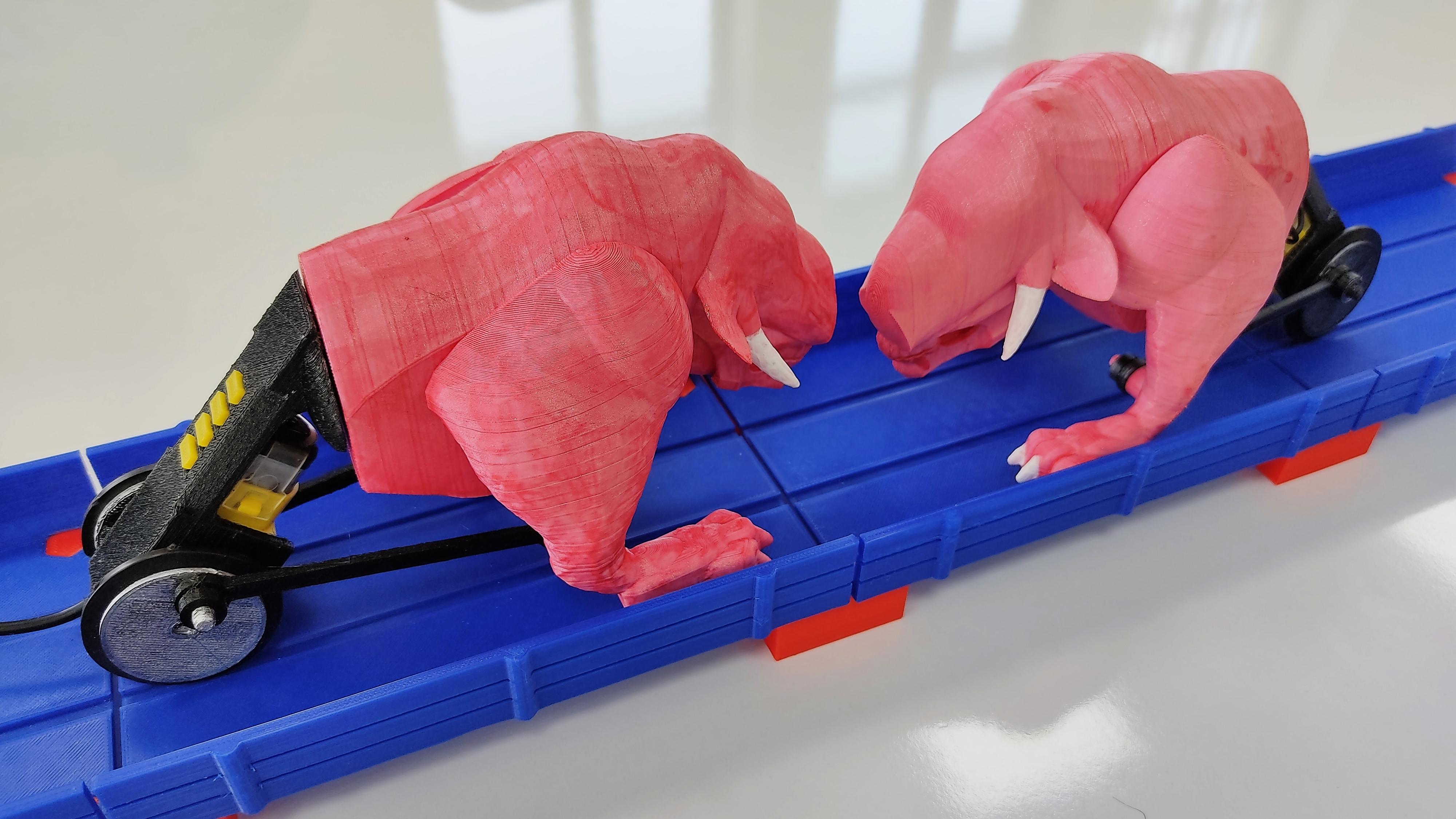
Bring your friends, and challenge them to control their Battle Beast, and to push their opponent out of the track. But remember, this game is not only about who spins faster. Use your brain and physics knowledge against your adversary.
Have Fun!