Tinkercad + Micro:bit Robotics for School: "I Love Kartof" Robot!
by M.C. Langer in Teachers > Robotics
10858 Views, 89 Favorites, 0 Comments
Tinkercad + Micro:bit Robotics for School: "I Love Kartof" Robot!
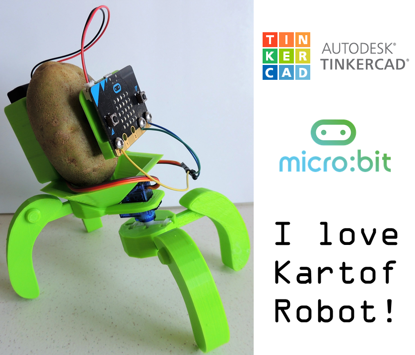
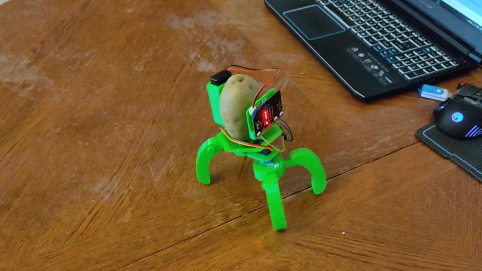
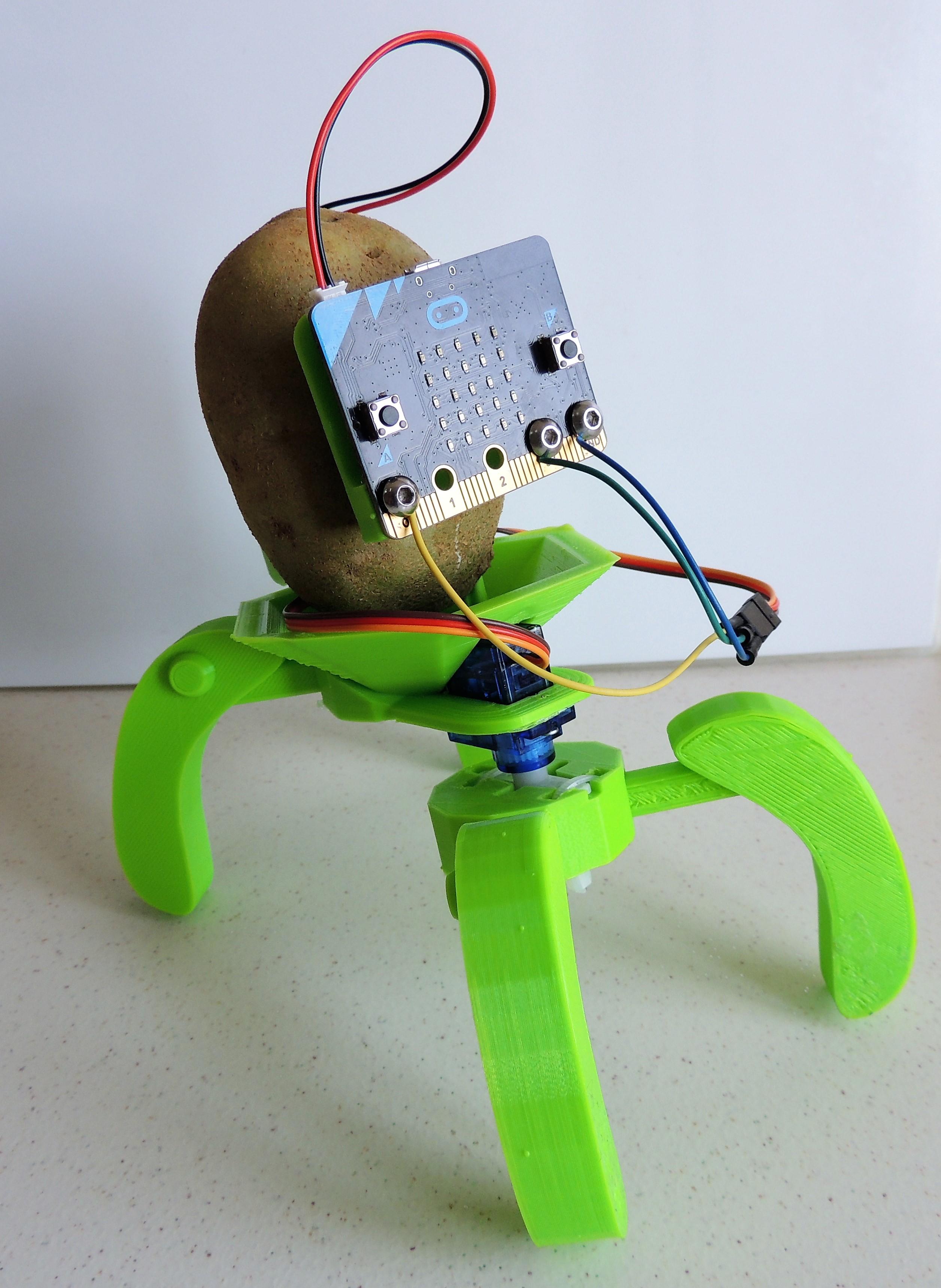
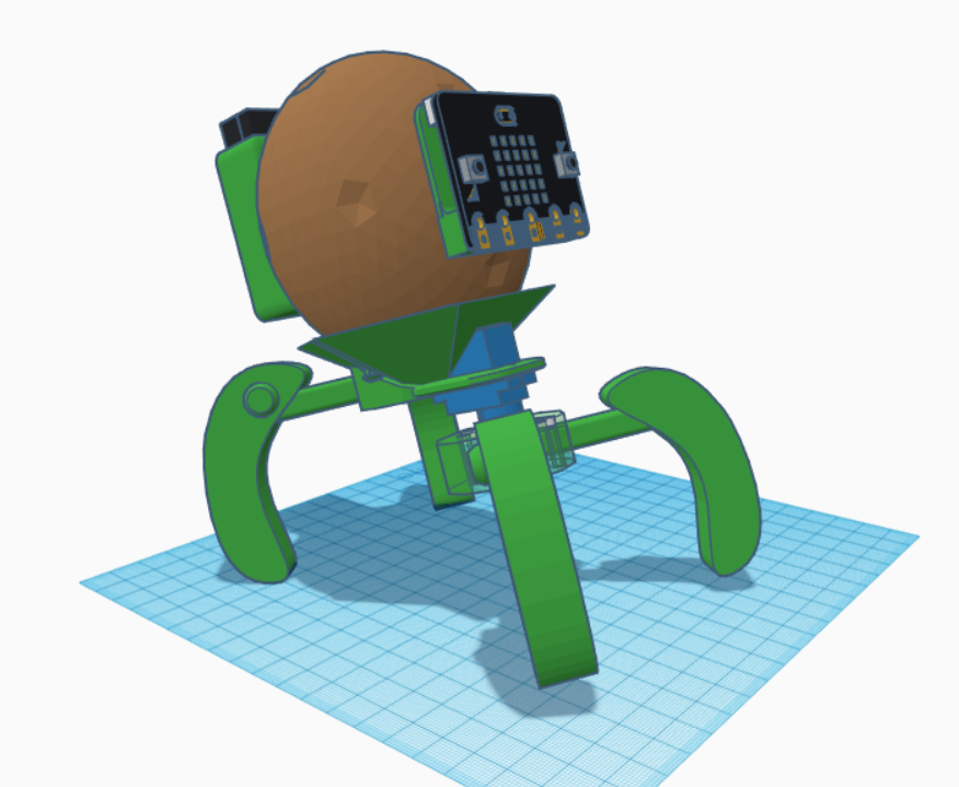
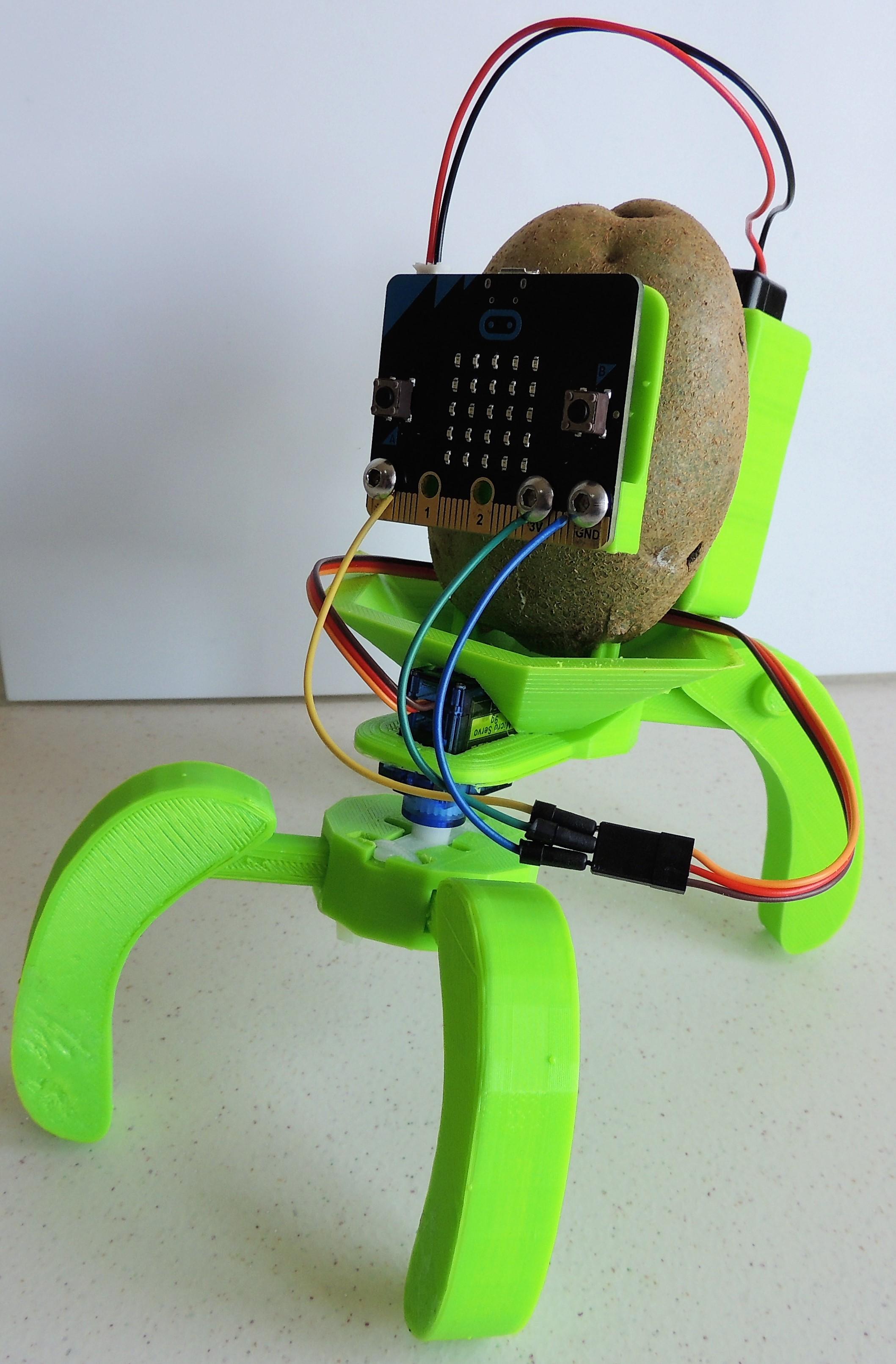
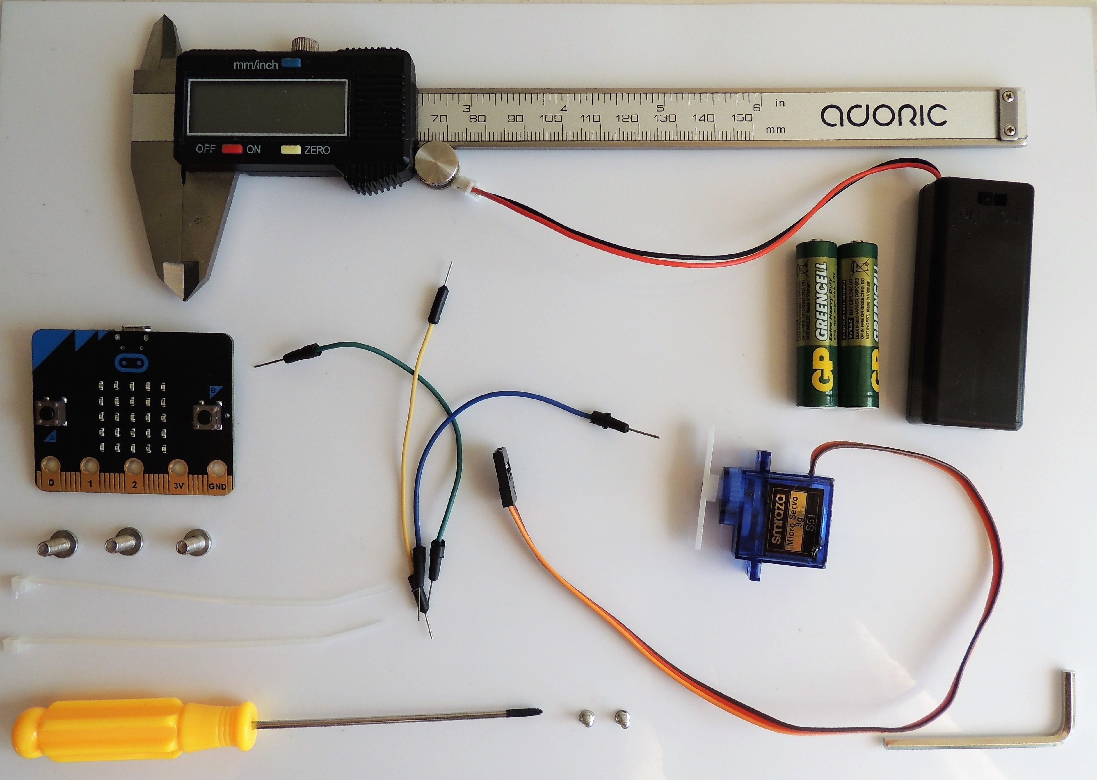
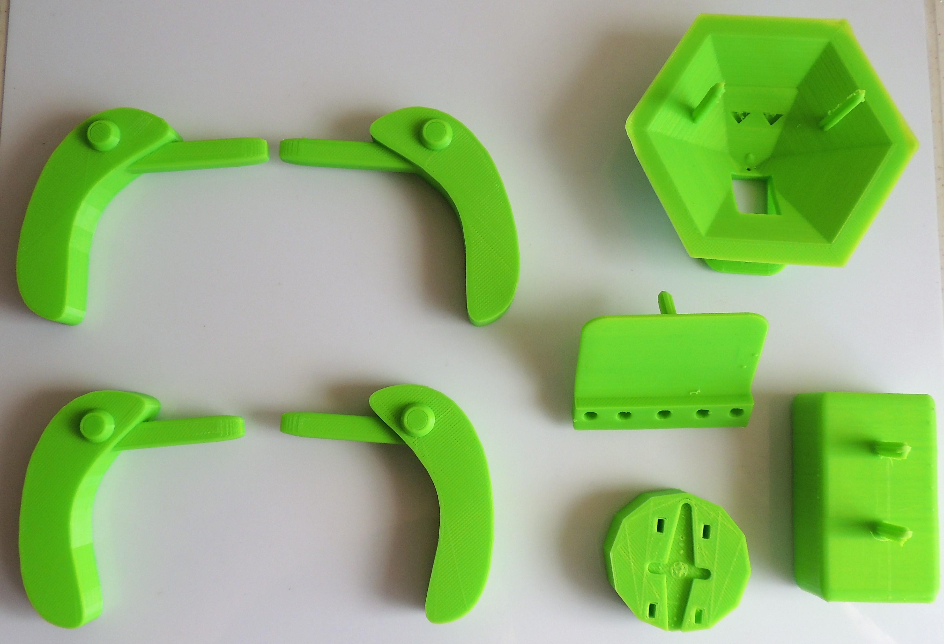
There is a word I love in Azerbaijani language: "Kartof". That means "potato". So, if one day you come to the streets of Baku and you want French Fries, the magic words are "Kartof Fri". In some restaurants they try to write it in an Americanized way, so if you see "Kartof Free", make no mistake: you still have to pay for the fries.
And for some reason, I love that "kartof" rhymes with "love". I always wanted to created a project with the words "Love" and "Kartof". I also wanted to put legs on a spud, since that day I created a vibrating potatoborg.
Well... let's use the power combined of Tinkercad and Micro:bit to bring to life my silliest invention of the year!
This could be an interesting and fun project for students of grades 5-7. So today we will learn hoy to apply CAD, 3D Printing, Engineering and Coding to create a technologically augmented tubercle. First, students will need Tinkercad to design and 3D print some special mechanical components, critical for the movement of our robot. Second, students will use Makecode to create the code for the Micro:bit board of their robot. Then, when the 3D printed parts are ready, kids will assemble the robot.
This project has the following constraints:
- Small Printing Area: my 3D printer is a Biqu Magician (small but faithful), and its printing area is only Φ100 x 150mm; so no piece of this project could exceed this area.
- Efficiency: the target is to give quadrupedal motion to a potato using only one servo and the power of 2 AAA batteries, so the design must be strong, but at the same time, light to avoid adding extra weight.
- Simplicity in materials: this robot is intended to be built using a simple Micro:bit starter pack, plus a servo and some wires and screws. And of course, a potato.
Students will require to have some prior knowledge of Tinkercad in intermediate level (workplane navigation, basic Boolean operations, group, ungroup, mirror and align, how to improve their own design).
DEFINITIONS:
3D Printing: or Additive Manufacturing, is a process used to create a physical (or 3D) object by layering materials one by one based on a digital model.
Bionics: application of biological methods and systems found in nature, to the study and design of engineering systems and modern technology.
CAD (Computer-Aided Design): use of computers to aid in the creation, modification, analysis, or optimization of a design.
Caliper: device used to measure the distance between two opposite sides of an object.
Potato: root vegetable native to the Americas, a starchy tuber of the plant Solanum tuberosum, and the plant itself is a perennial in the nightshade family, Solanaceae. Best consumed fried and with ketchup.
Servo (servo motor): component that integrates a motor, a gear box and a sensor to control the position of the shaft.
SUBJECTS:
Science (Physics), Robotics, Art, Handwork, Computer Science, Computer-Aided Design (CAD), 3D Printing, biology, biomimicry.
Supplies
- 1 BBC Micro:bit board
- 1 2 AAA Batteries holder with plug for Micro:bit
- 2 AAA Batteries
- 1 USB cable for Micro:bit
- 1 Servomotor with double-arm horn and screw
- 3 Jumper wires
- 2 zip ties
- 3 M4X10 bolts
- 2 small screws to attach the servo
- 1 pair of scissors
- 1 caliper
- 1 screwdriver
- 1 Allen Key
- 1 Computer with internet access
- 1 3D Printer, type: FDM. Printing material: PLA of 1.75 diameter
- Tools for 3D printing (needle-nose pliers, spatula, plus tool set included in the 3D printer’s box)
- Optional: multi-tool, hot glue gun.
Starting With Tinkercad: Micro:bit Plate
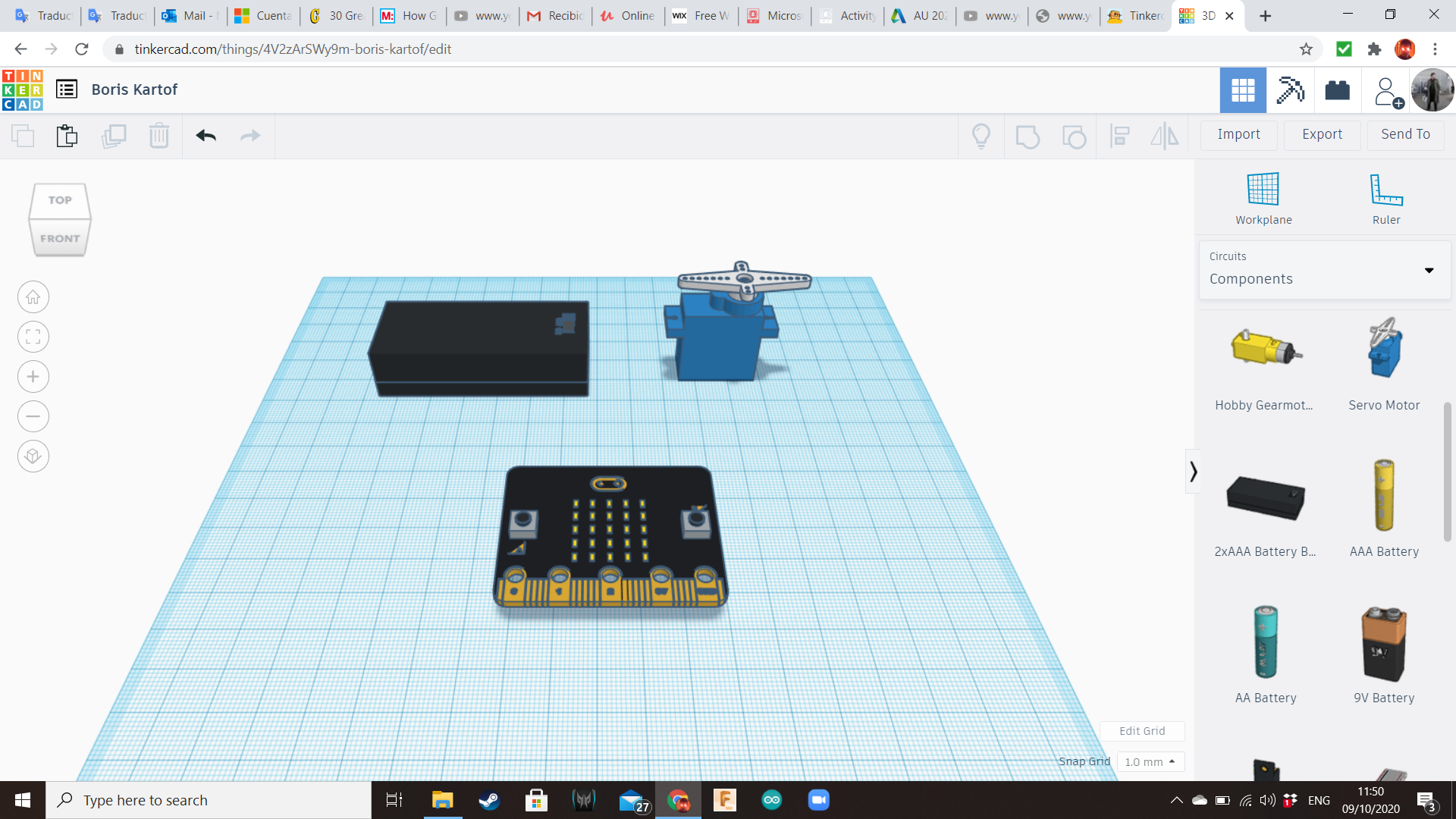
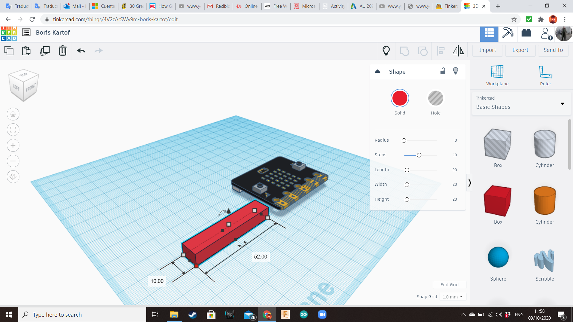
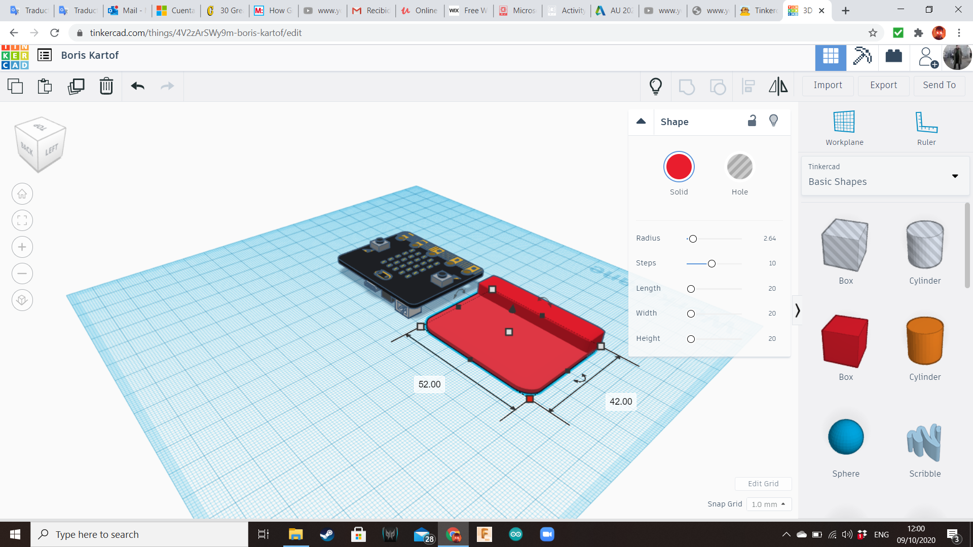
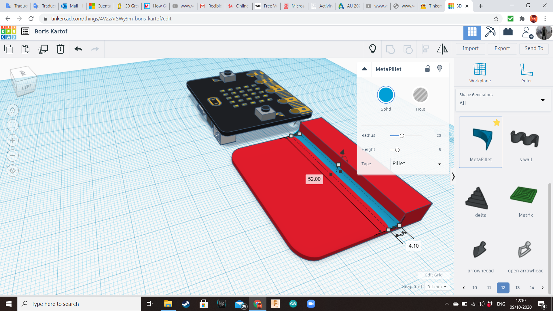
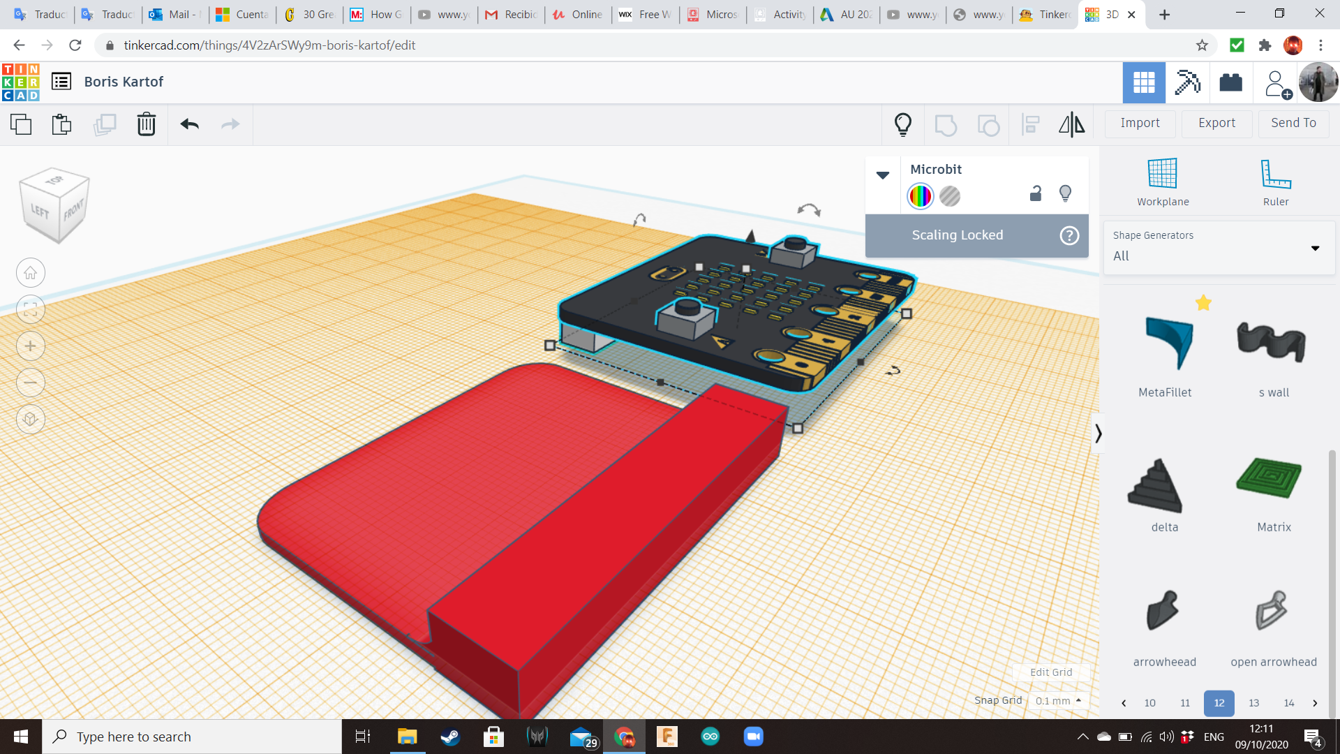
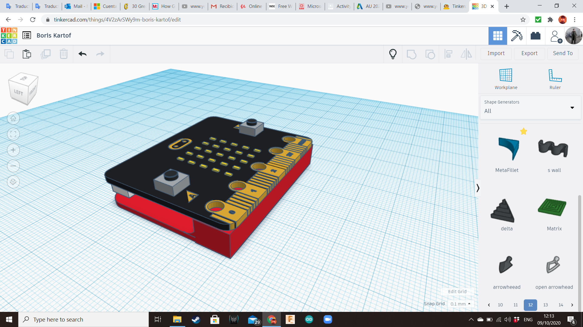
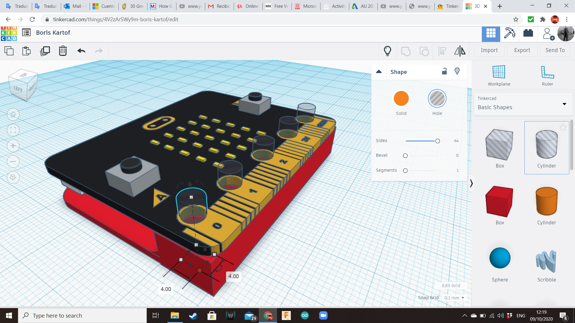
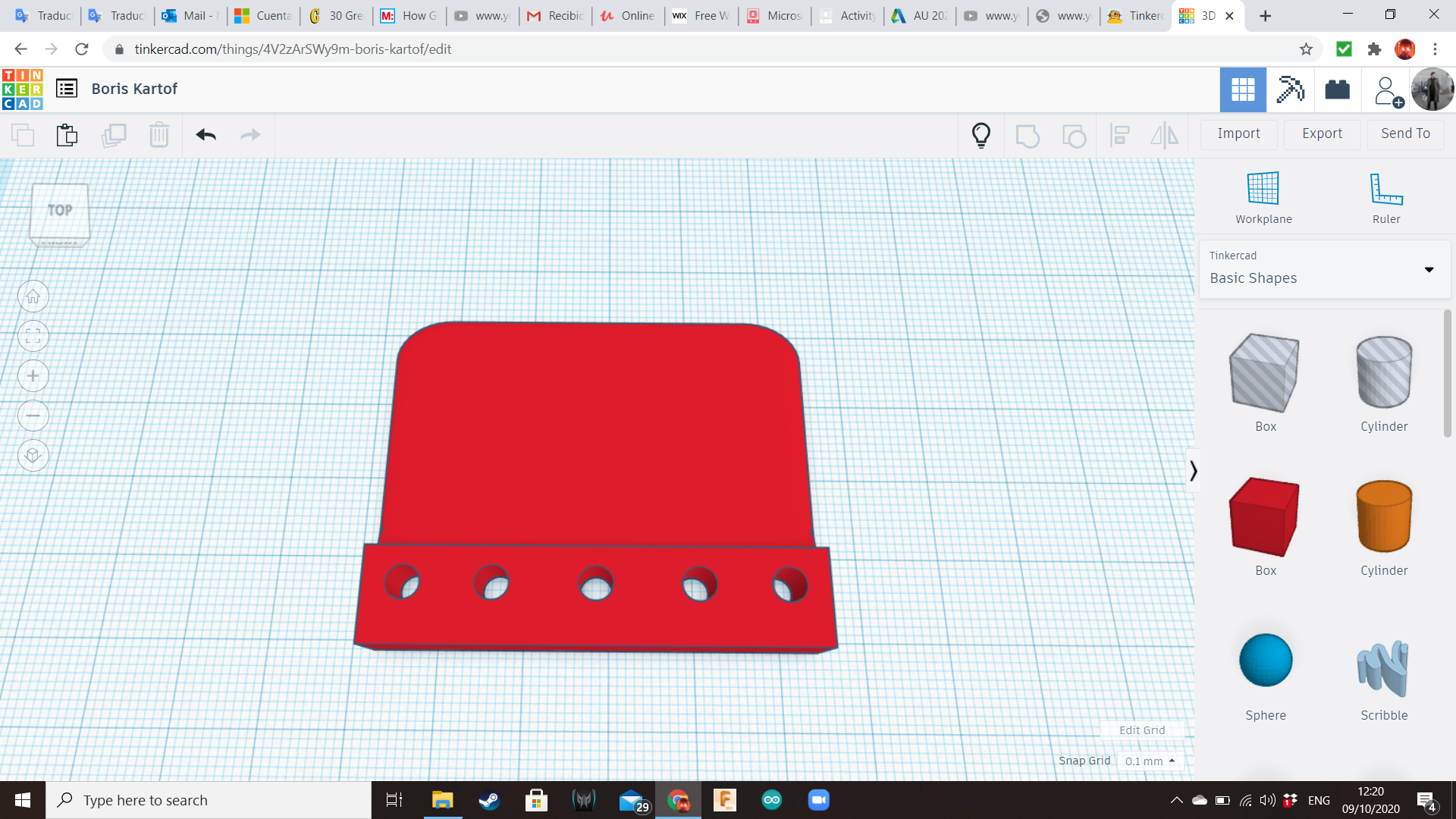
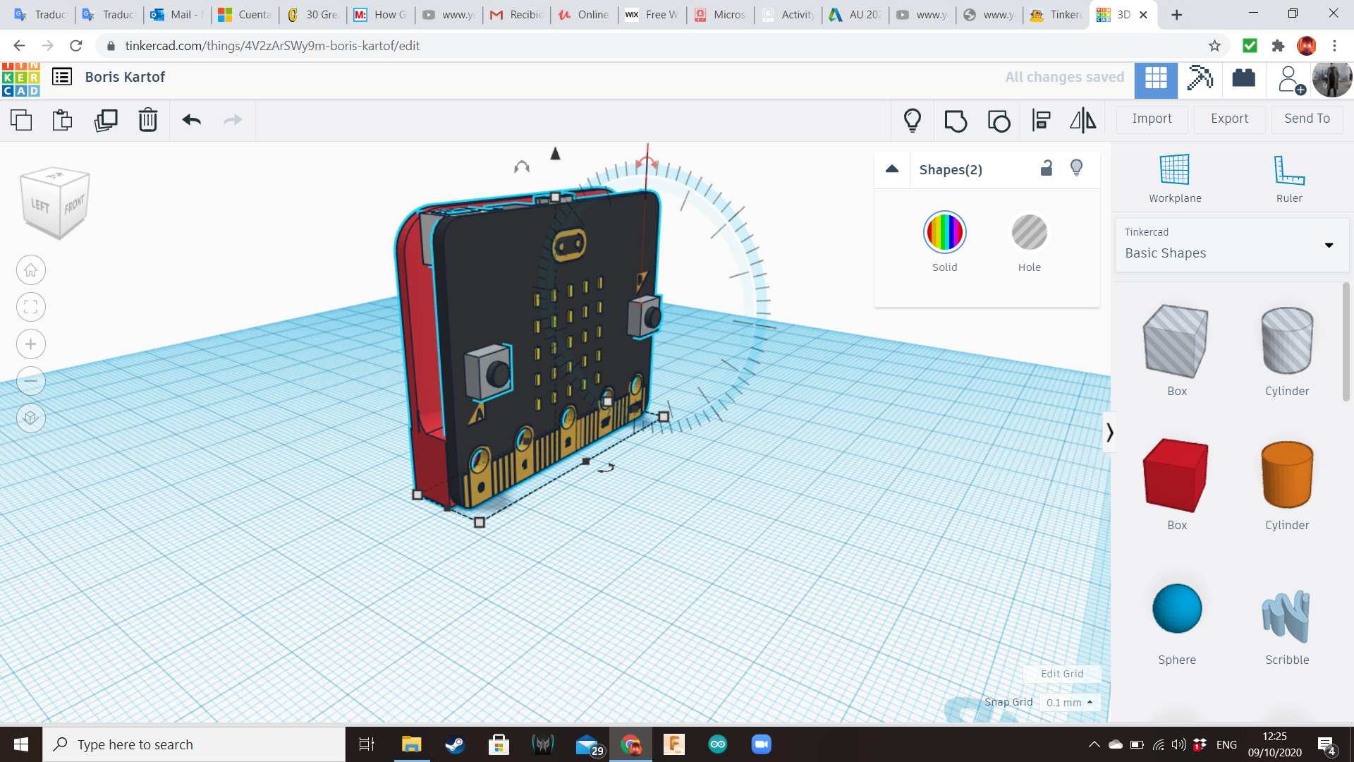
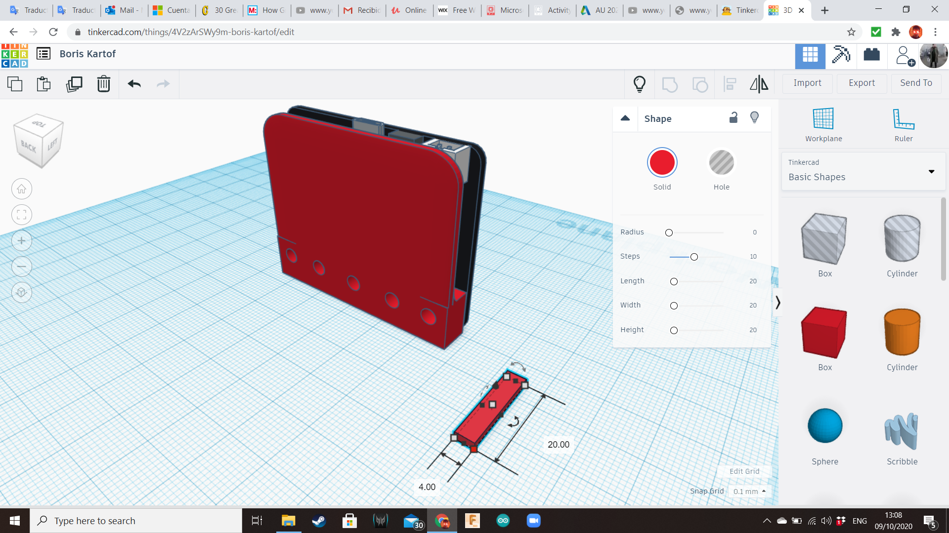
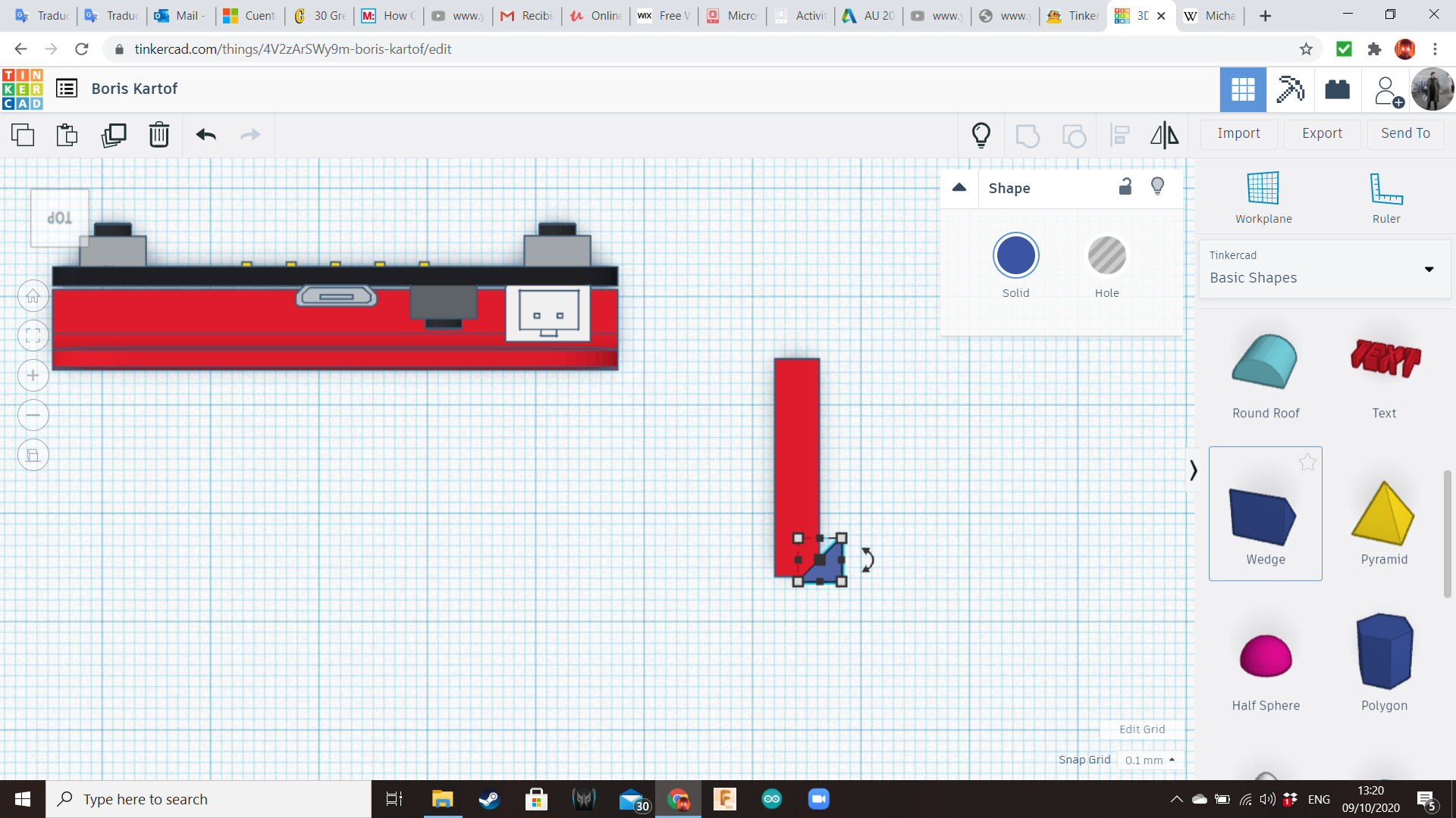
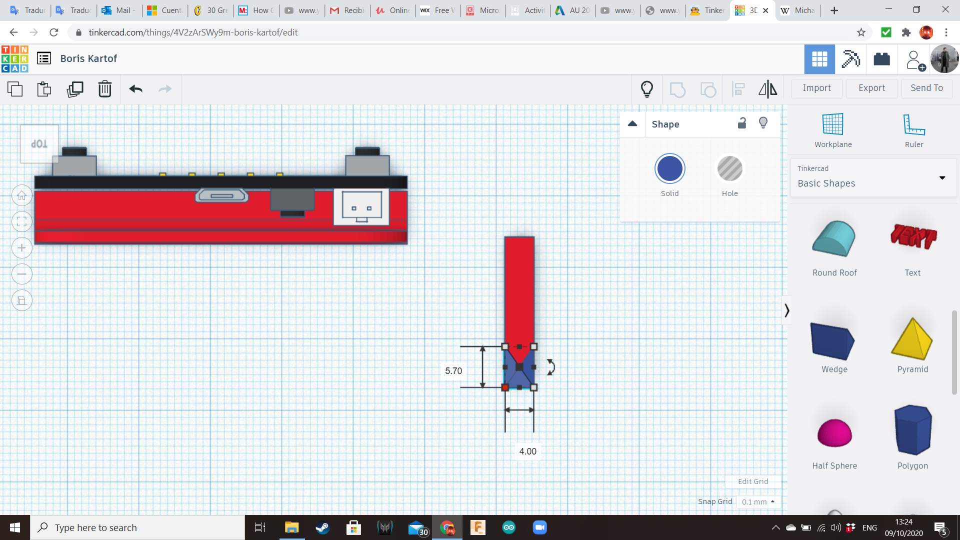
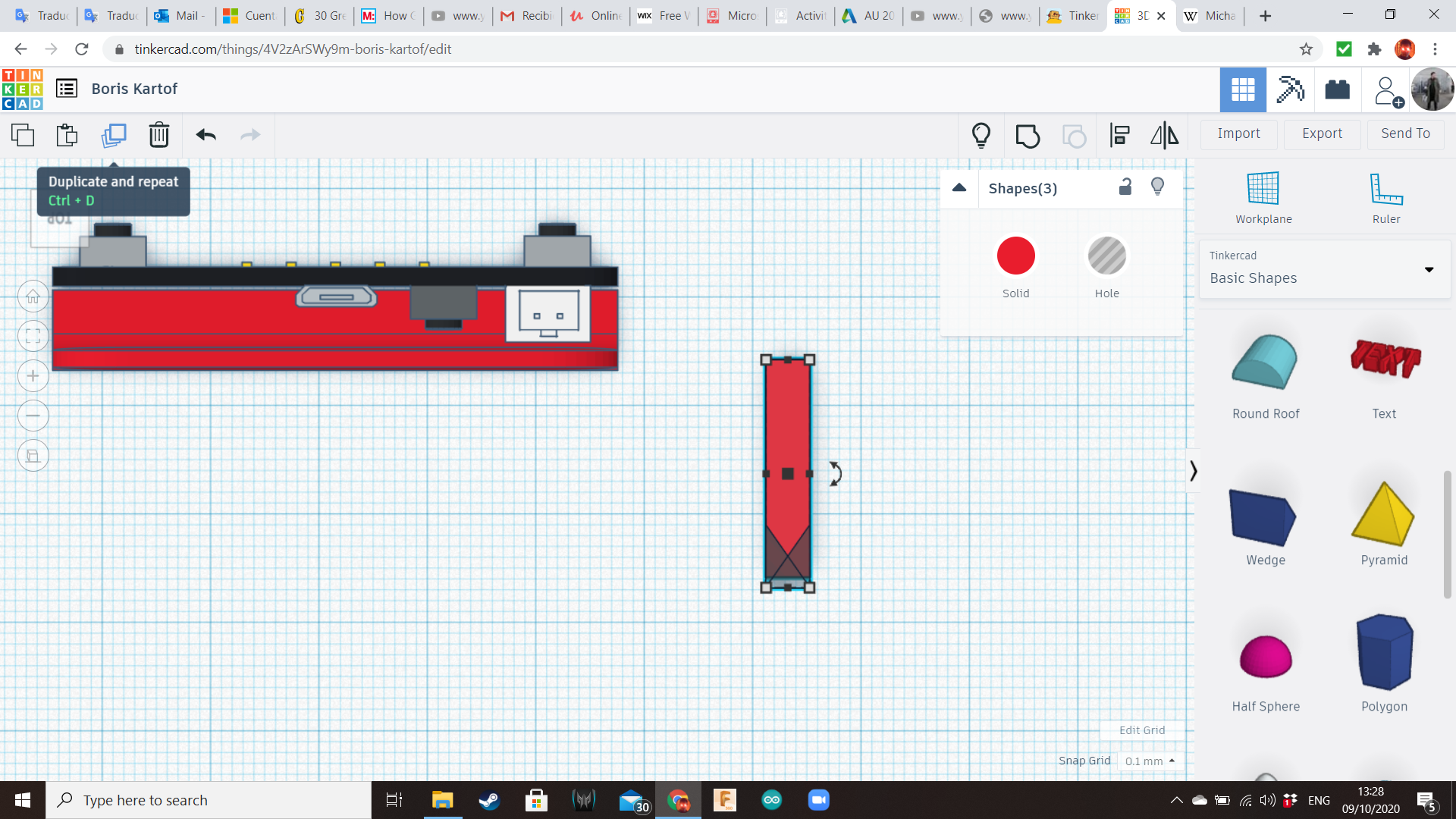
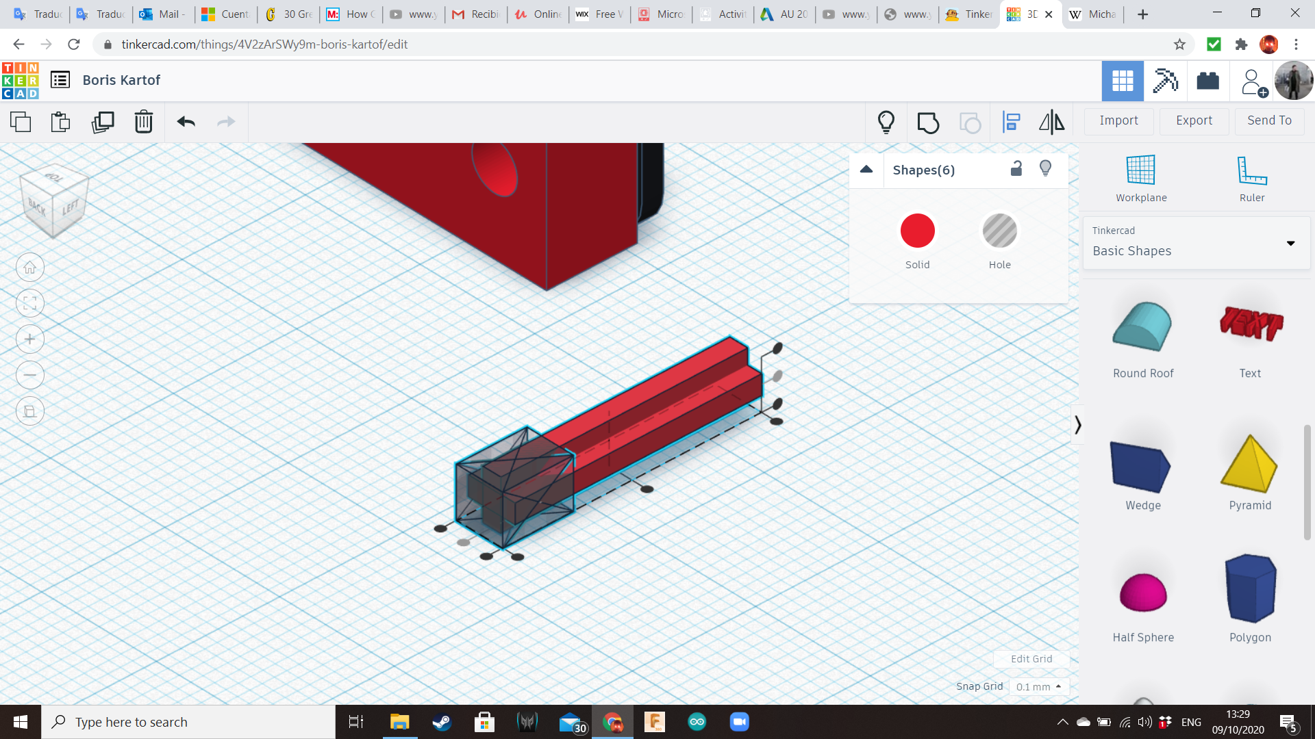
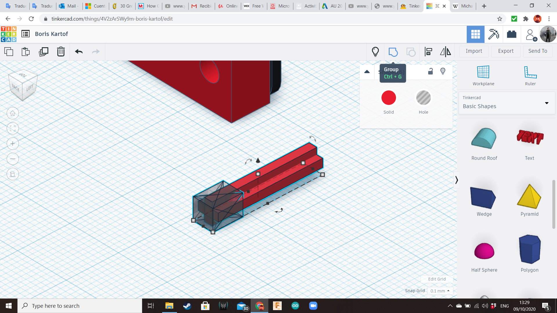
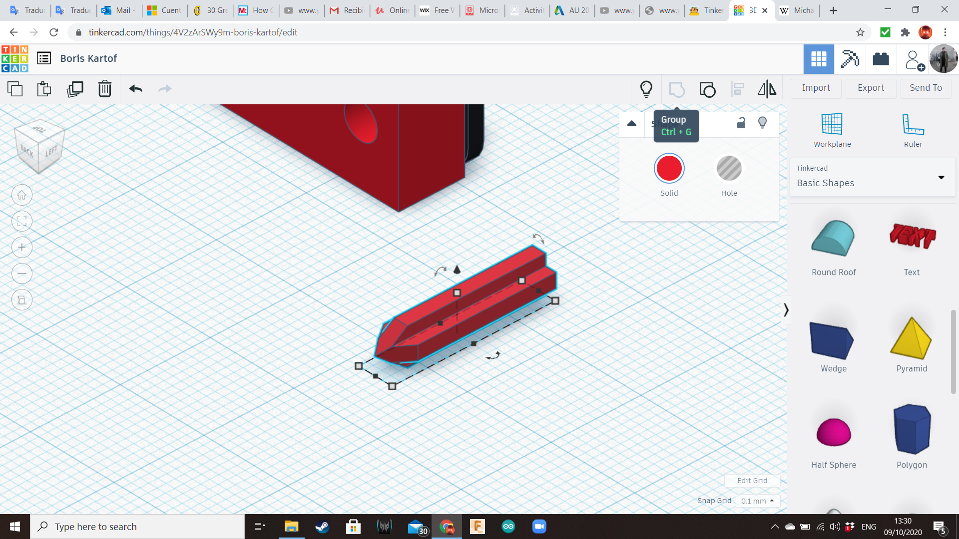
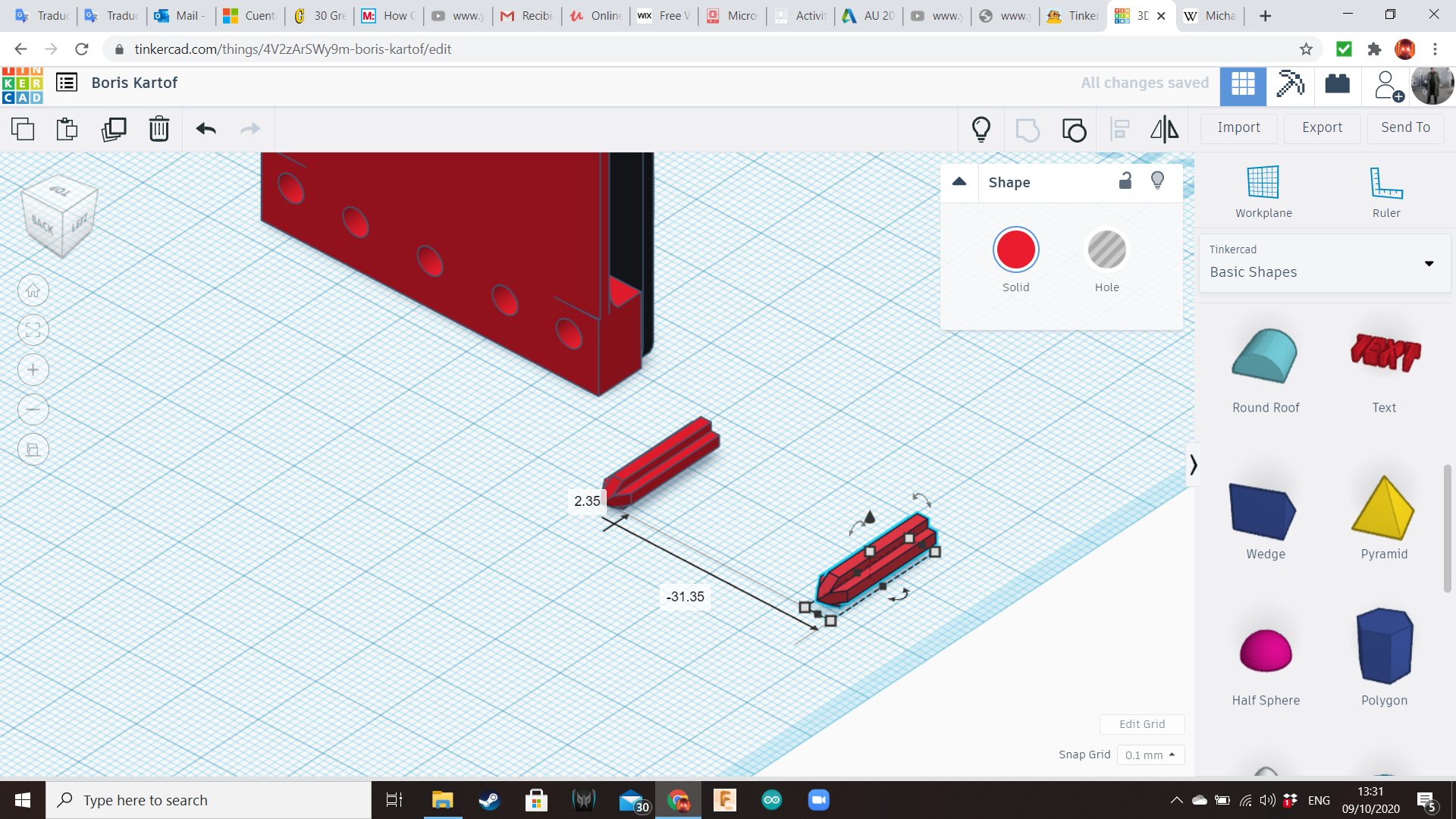
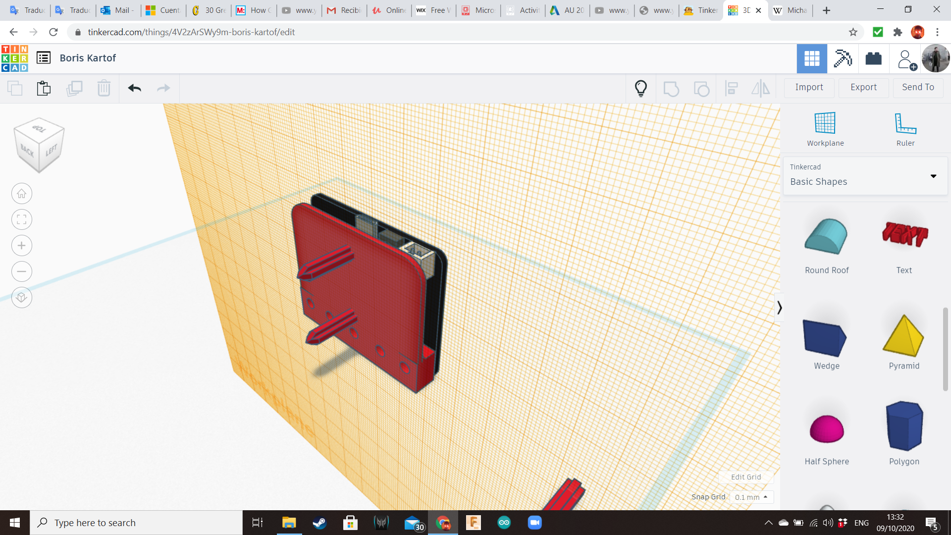
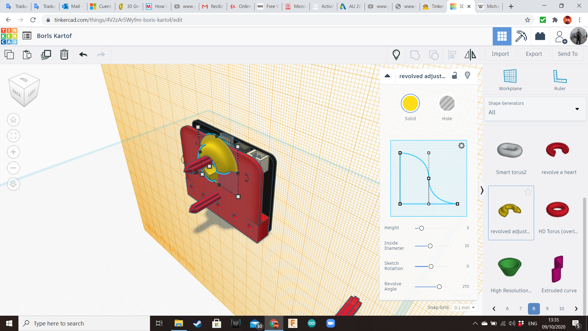
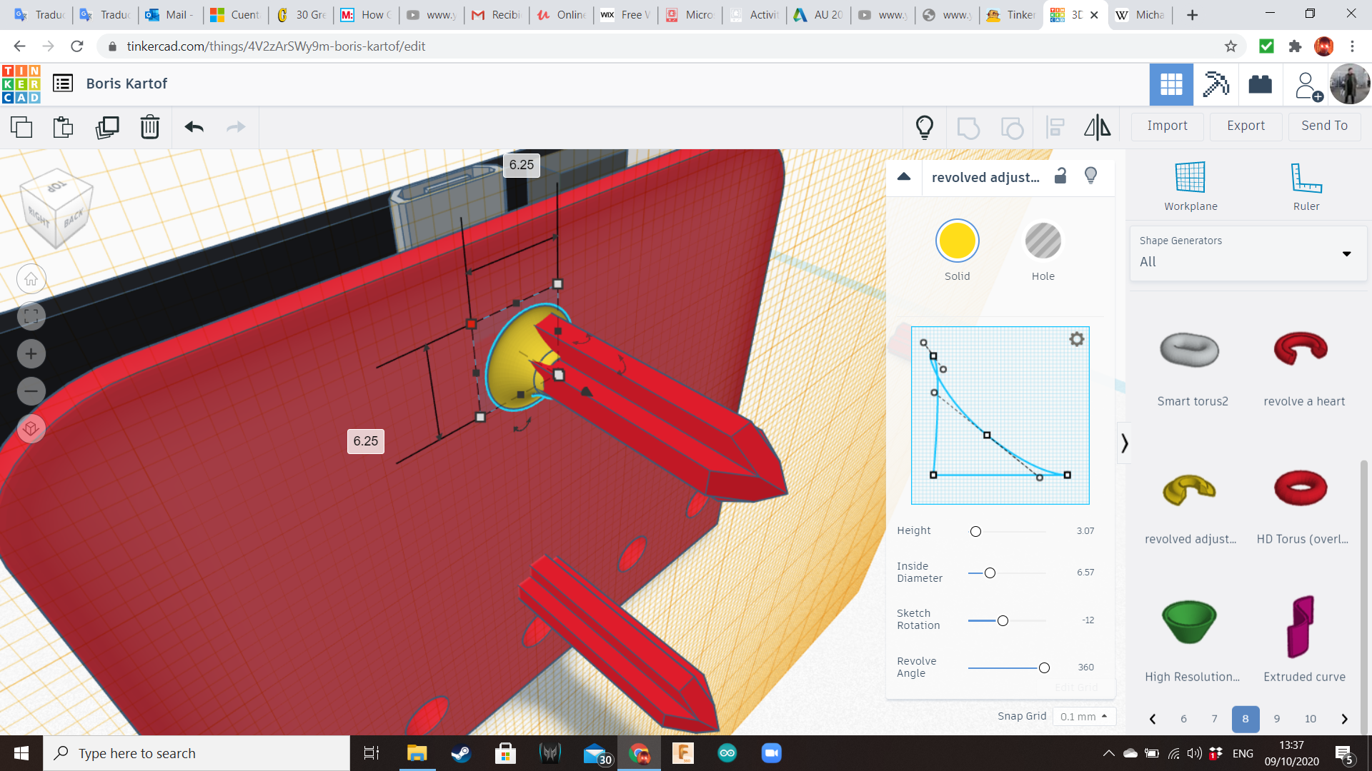
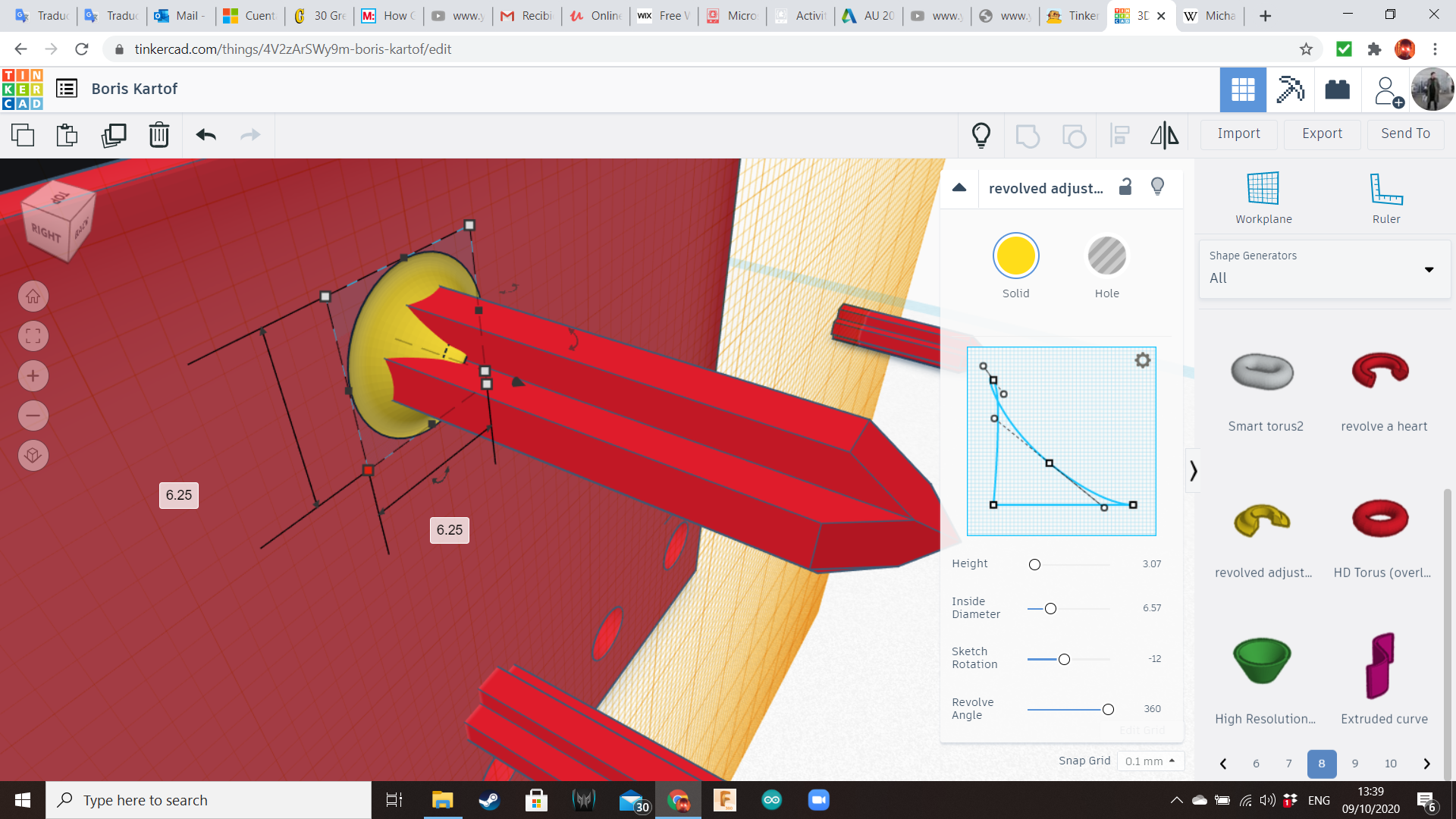
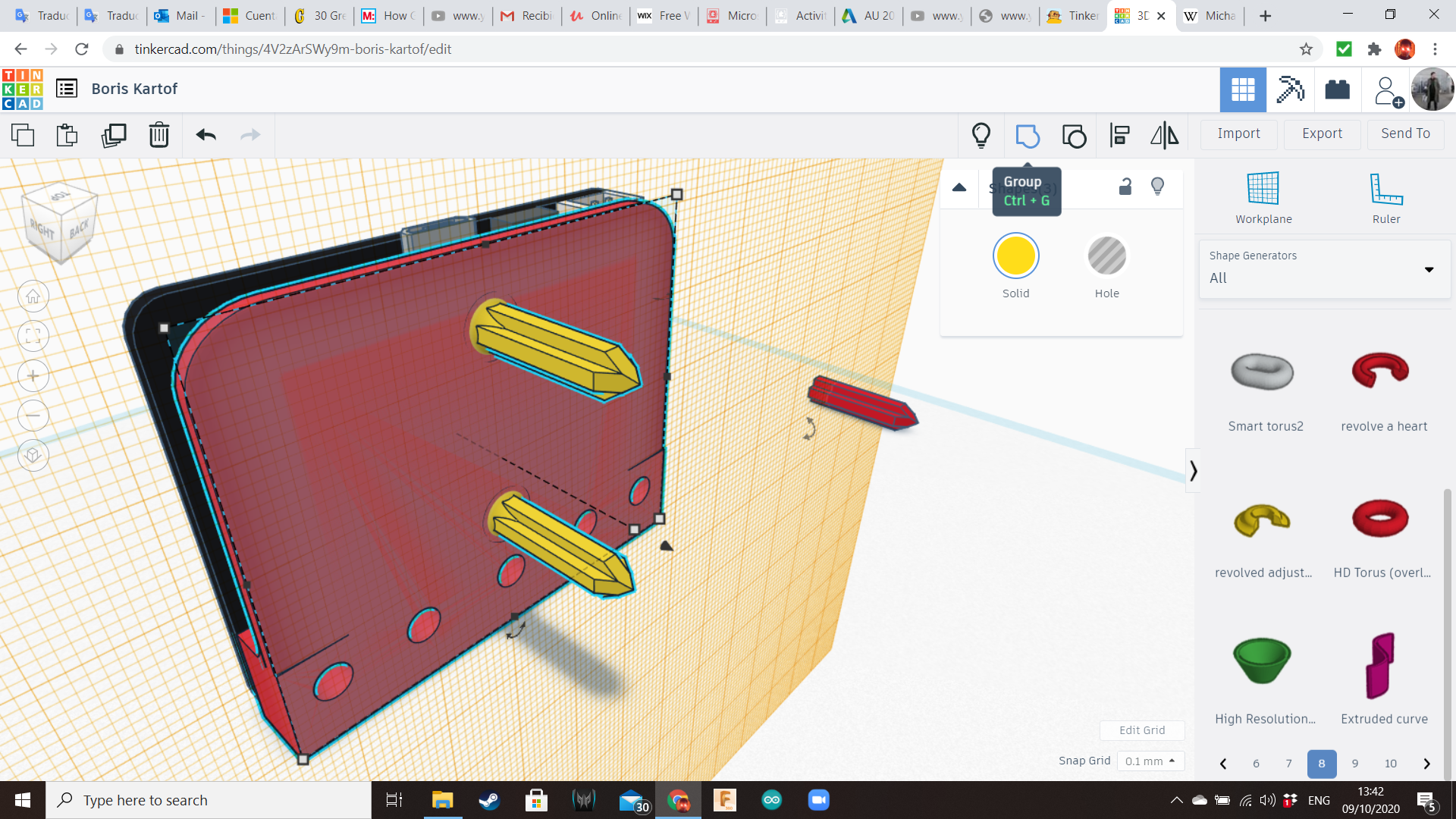
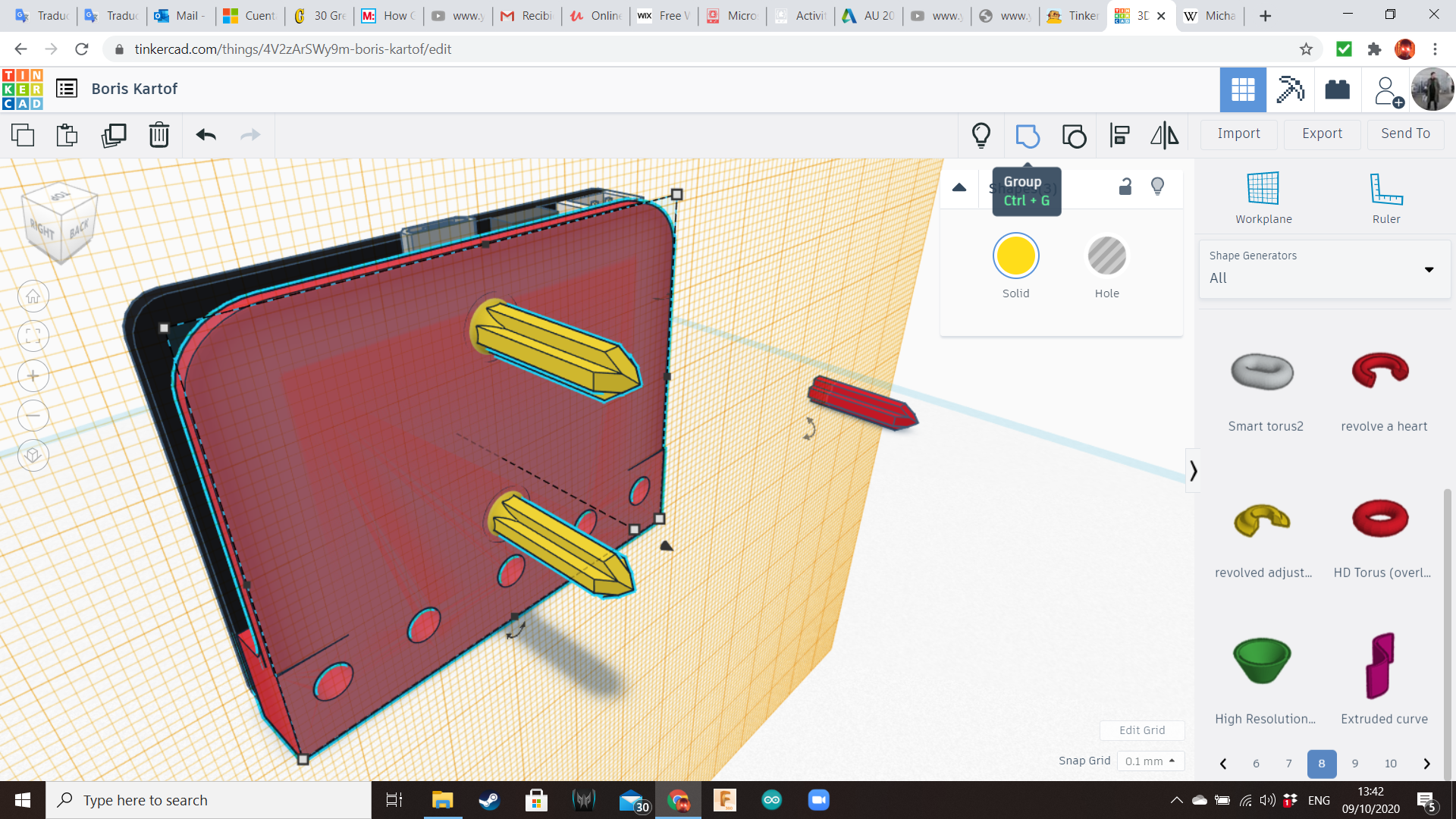
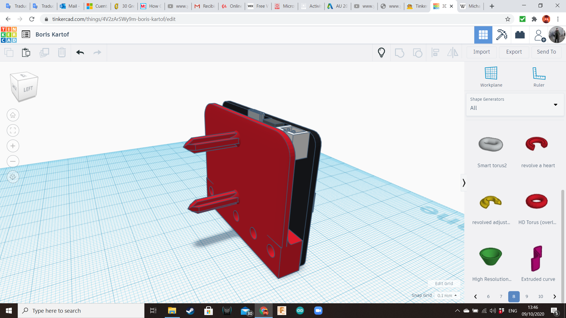
From the Circuits Library we will choose the following components: AAA Battery Box, Servo Motor and Micro:bit.
Let's start with the Micro:bit.
Create a plate using 1 box of the same length and width of the Micro:bit, and 1 box of the same width of the board, but the length must cover only the pins area. Hight must be 4 mm approximately.
Create 5 cylinders of 4 mm diameter, and align them with the pin holes of the Microbit.
At the end, create to "spikes", using boxes and wedges to make them pointy. That part will be inserted into the potato.
Battery Backpack
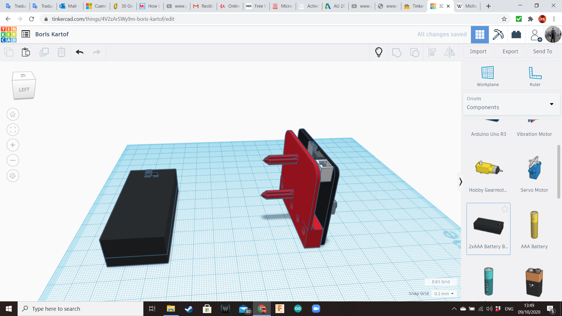
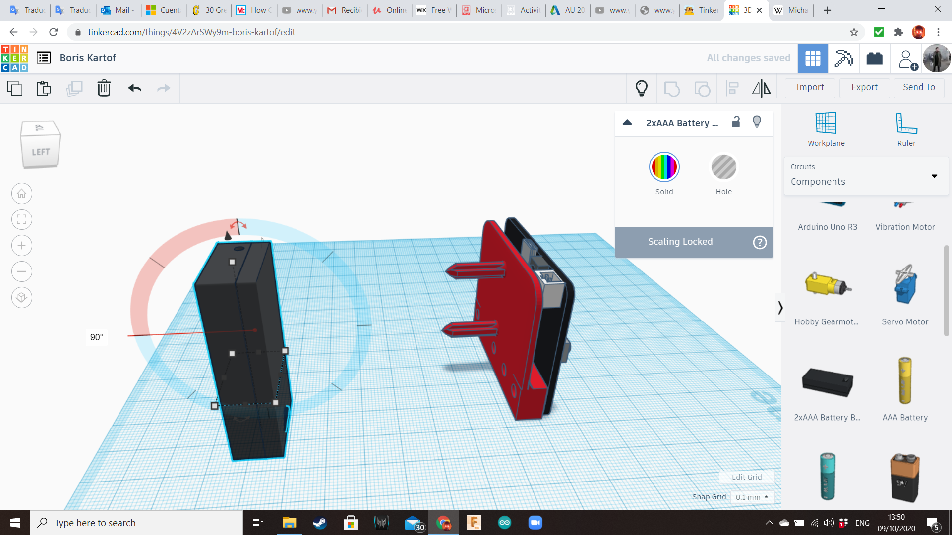
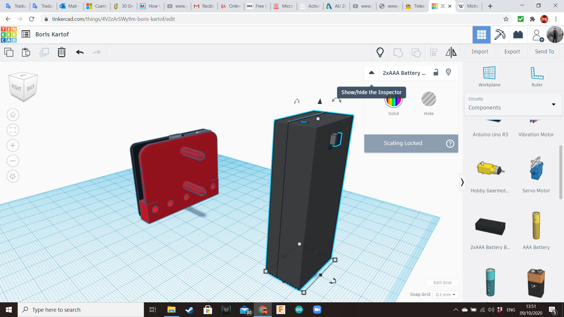
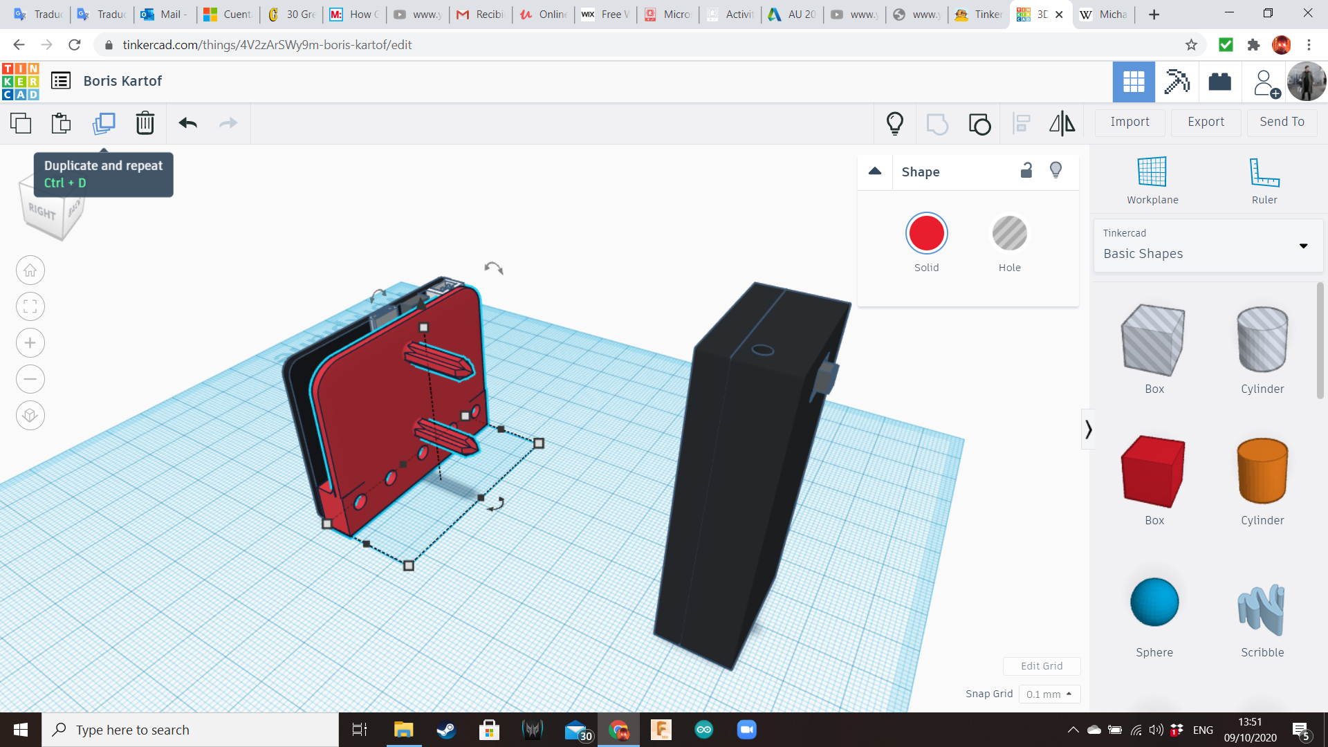
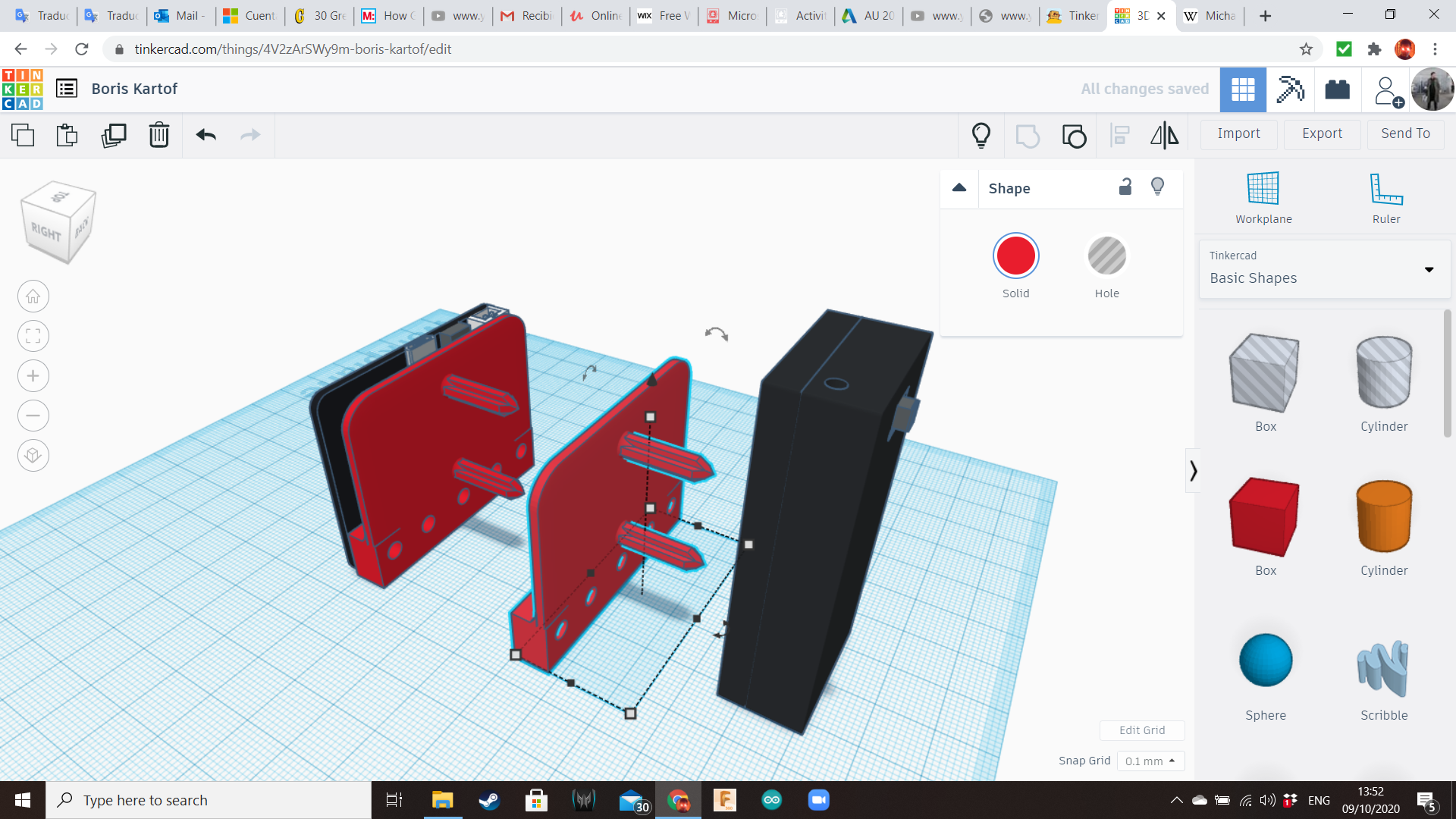
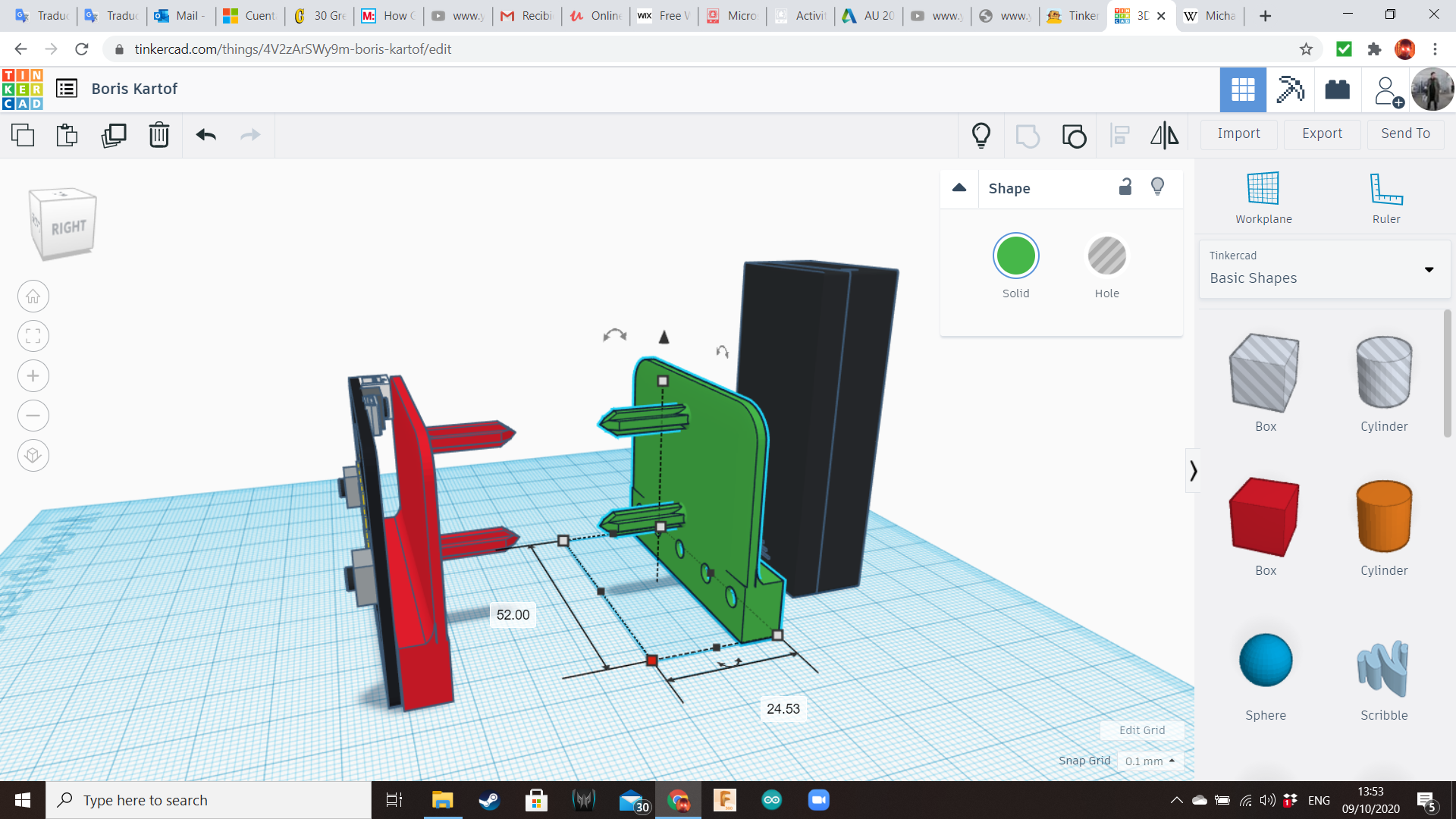
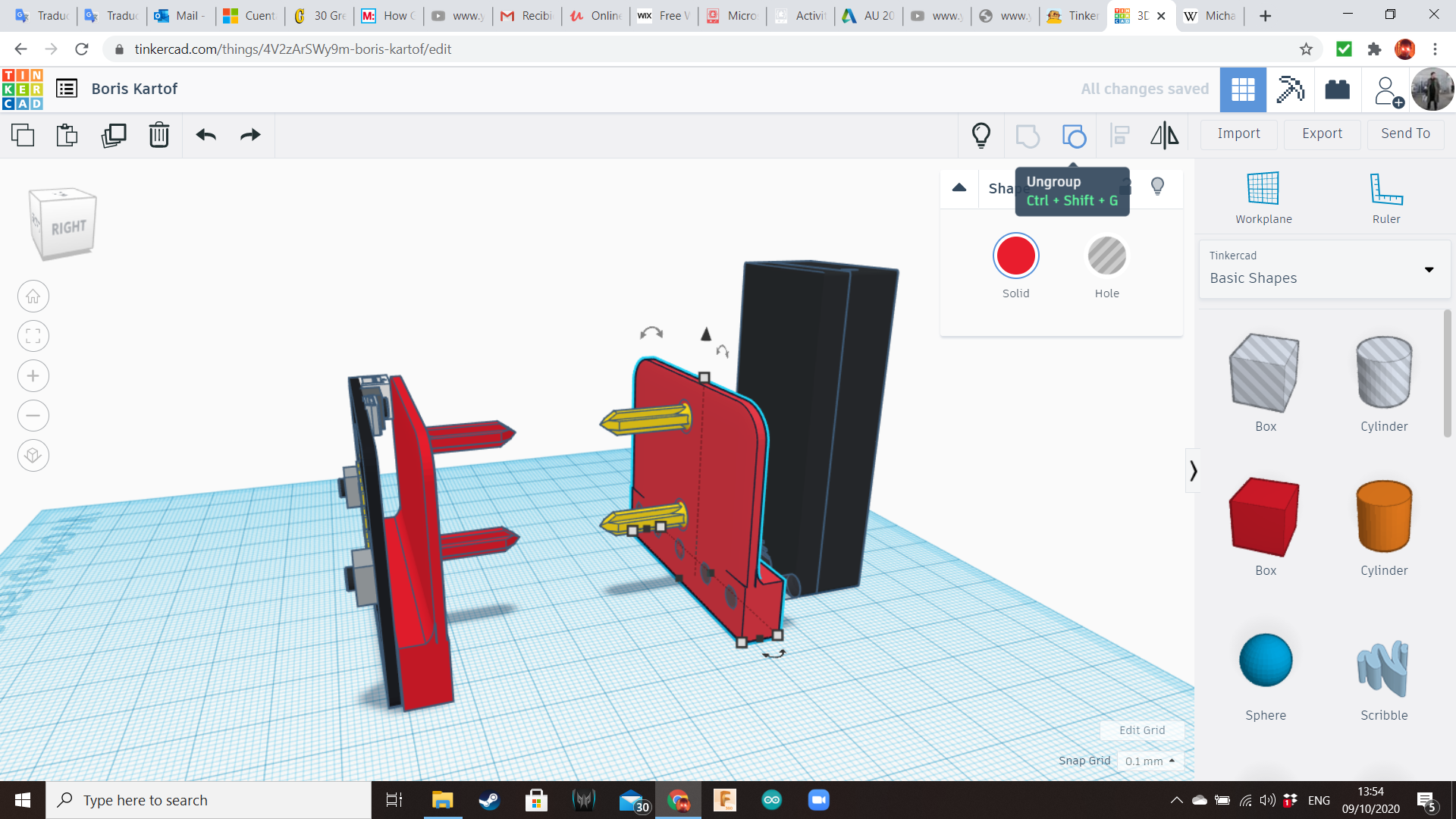
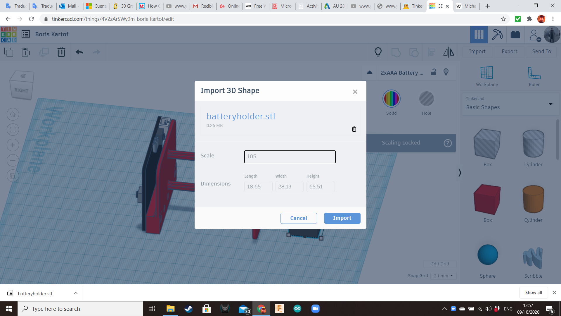
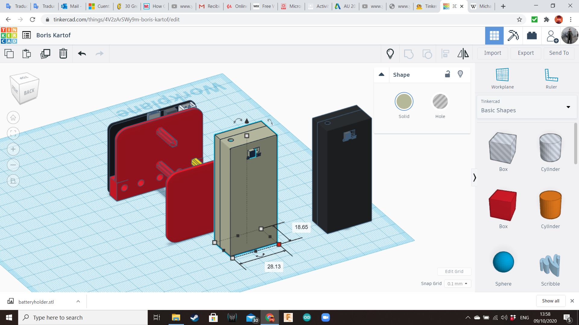
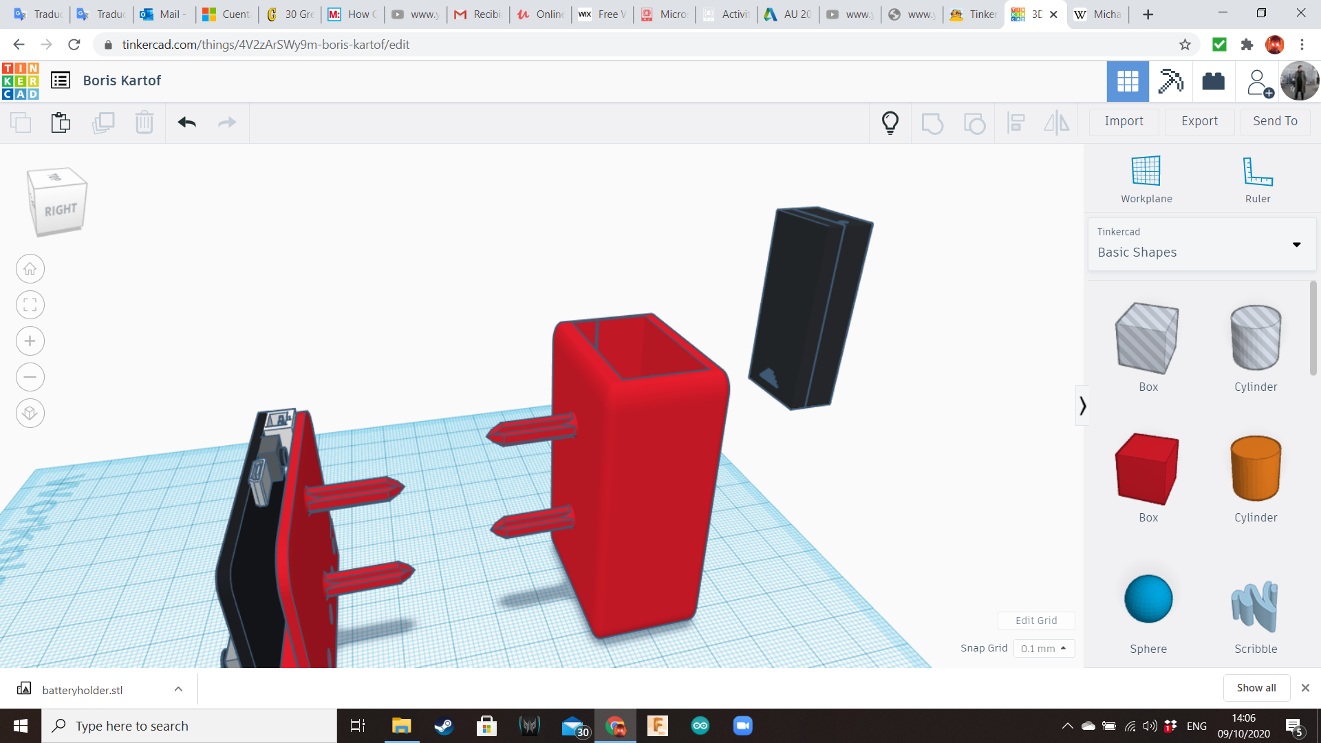
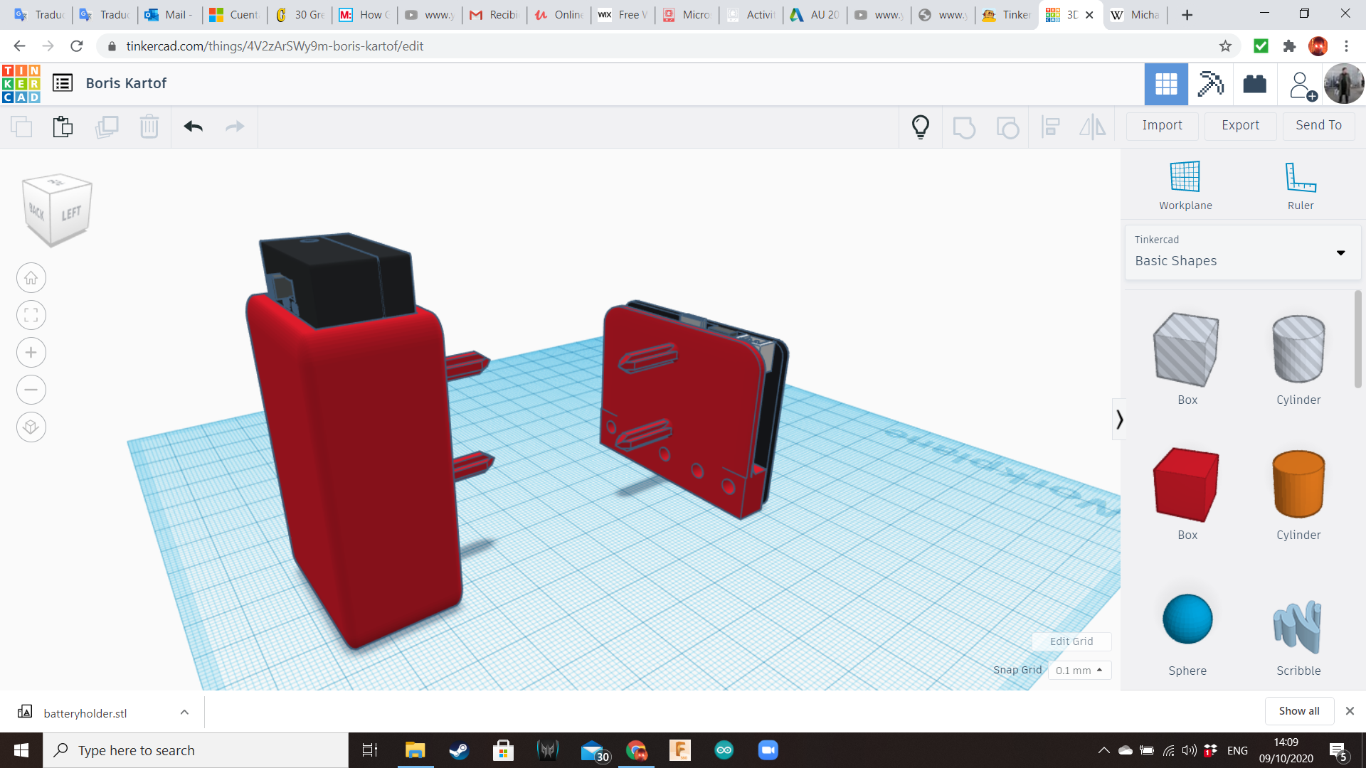
Now let's work with the battery box.
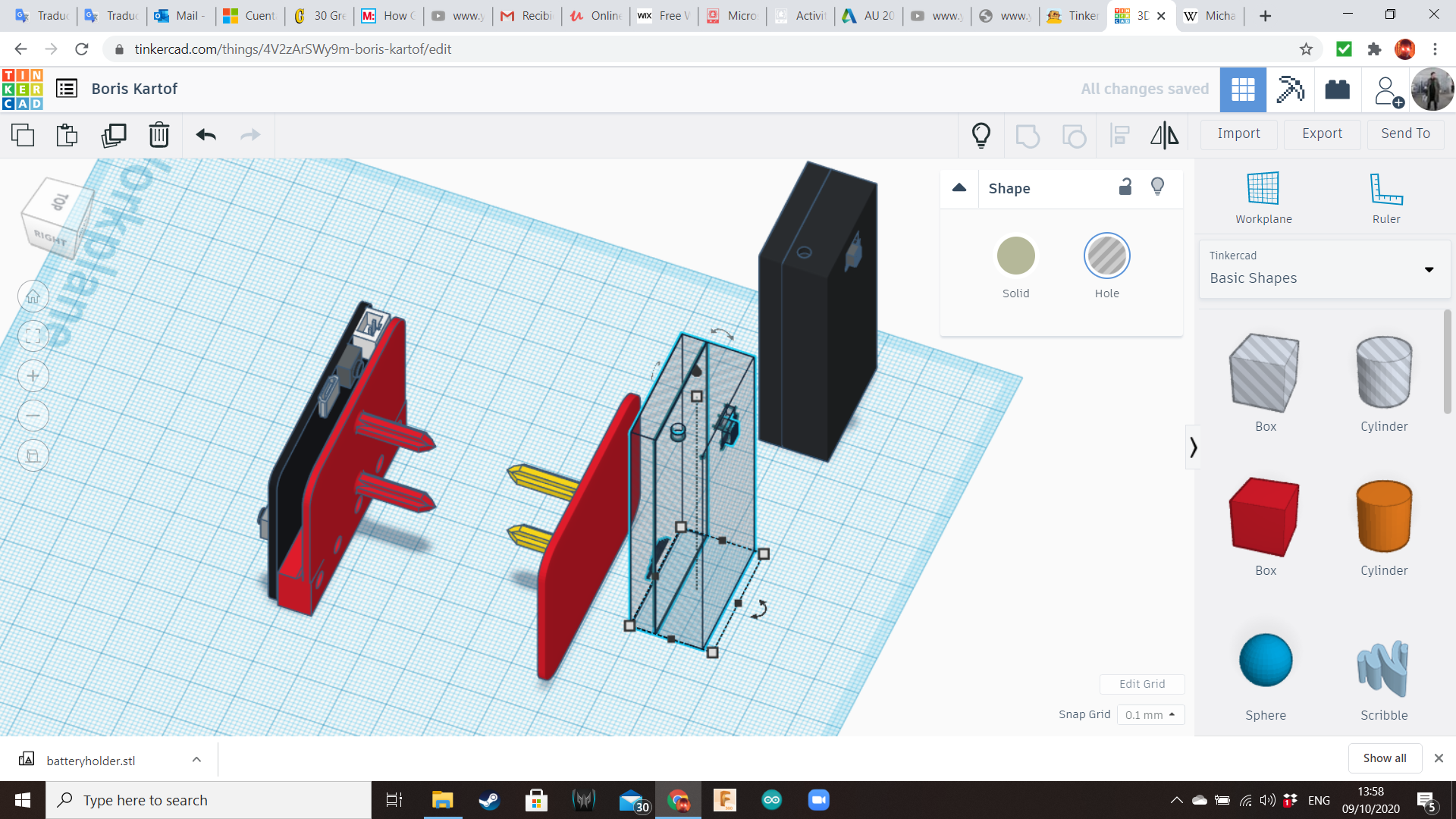
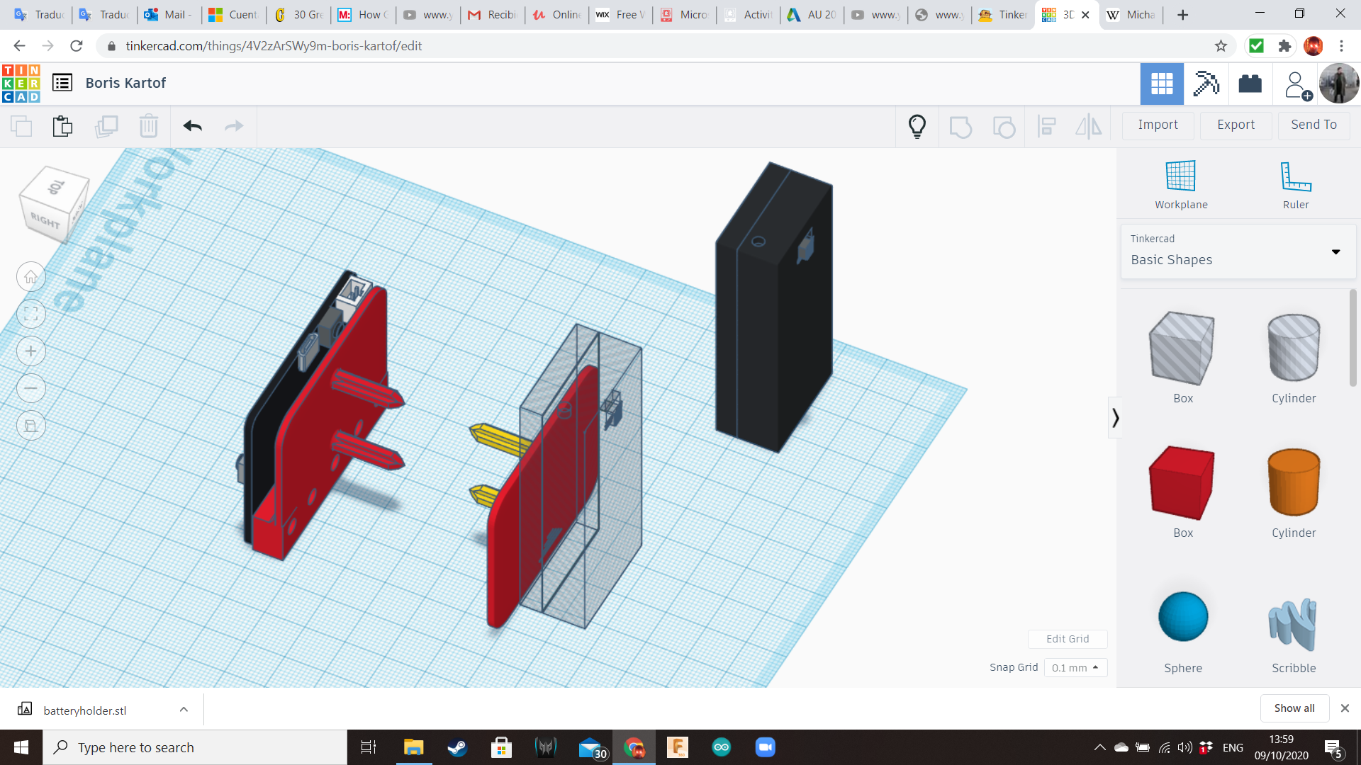
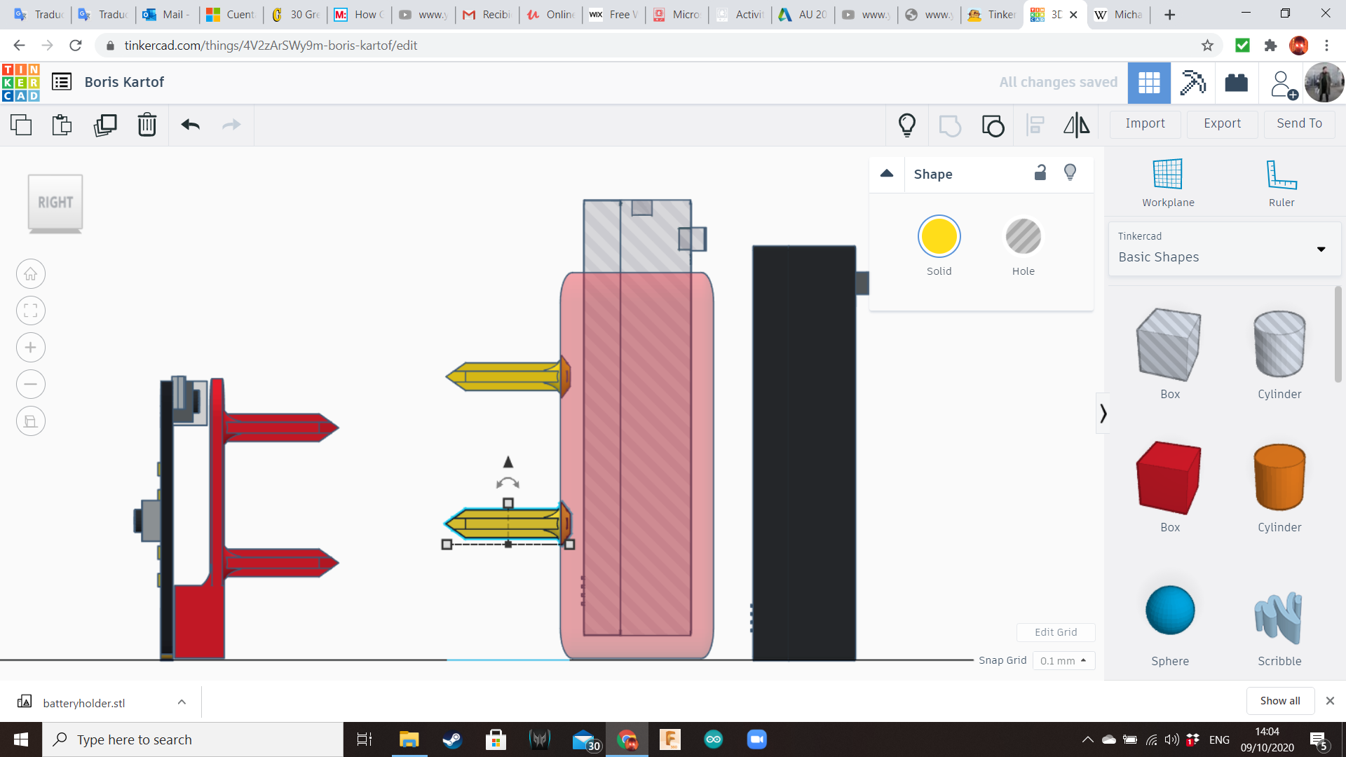
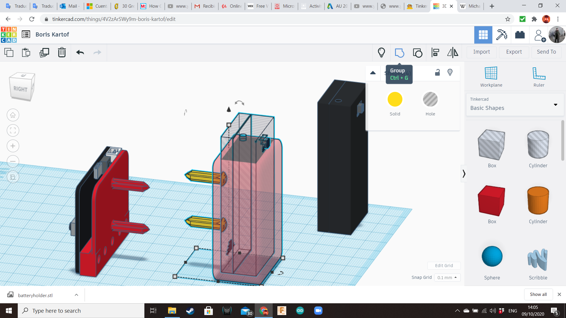
To save time, we can use the same plate of the Micro:bit board. Ungroup its components, and transform the main box into the backpack. For the hole dimensions, you can measure a physical AAA battery holder using the caliper, or you can export Tinkercad's battery box and import it again with a 105% scale. For a more detailed explanation about how to do this, check the photos from the Step 19 of my previous instructable. Don forget to leave enough available area on top to allow access to the switch.
Potato Base
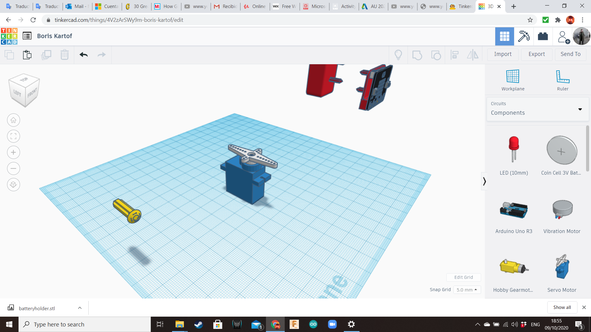
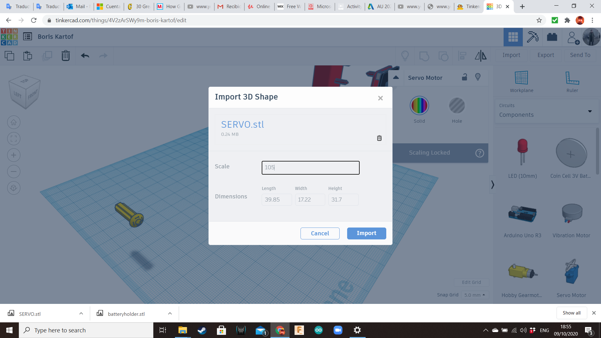
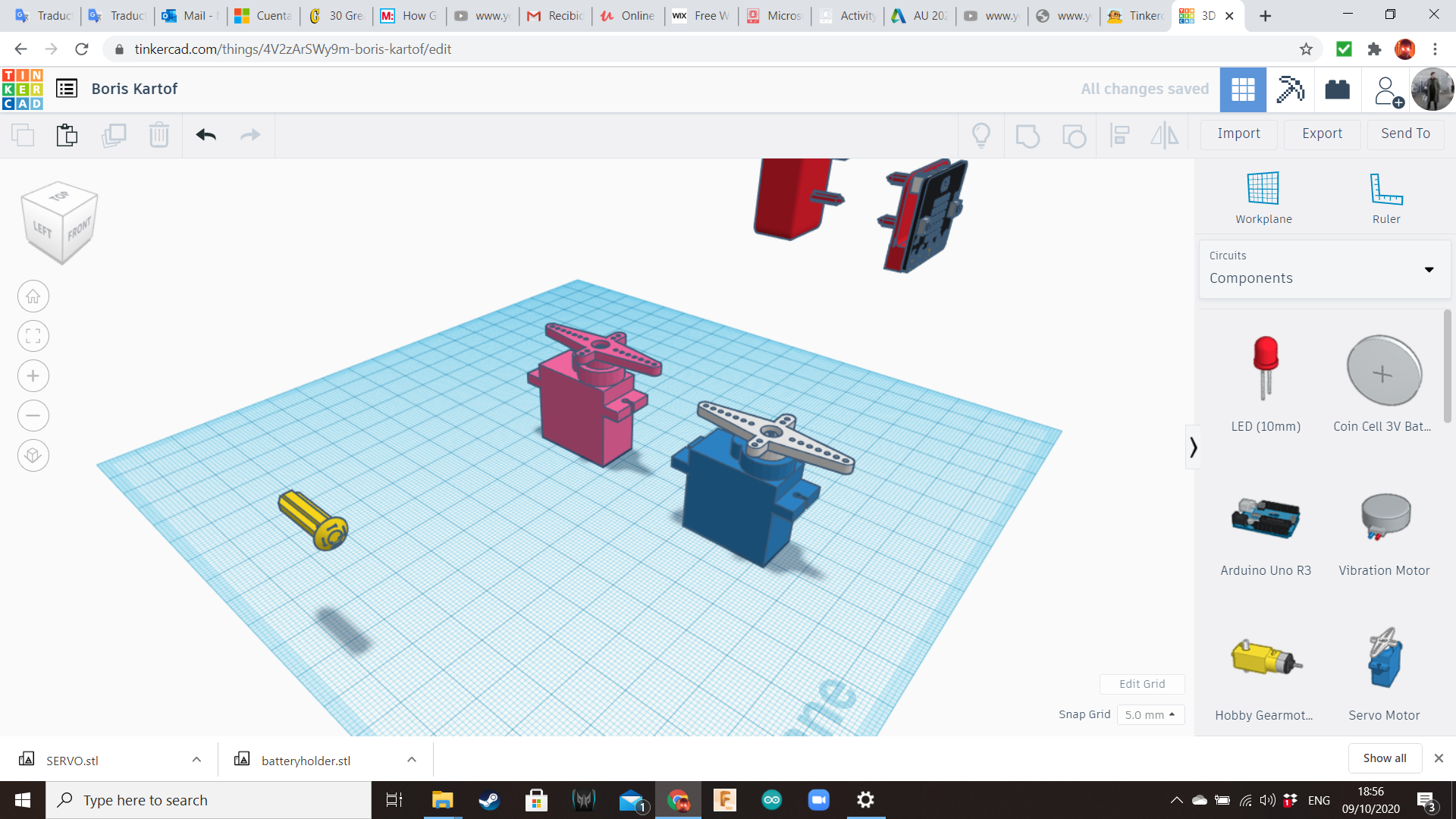
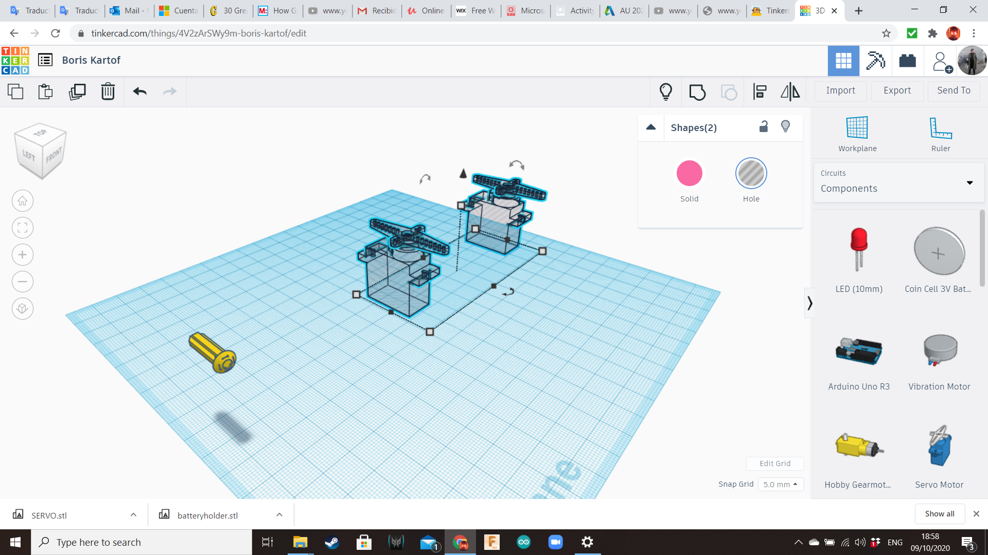
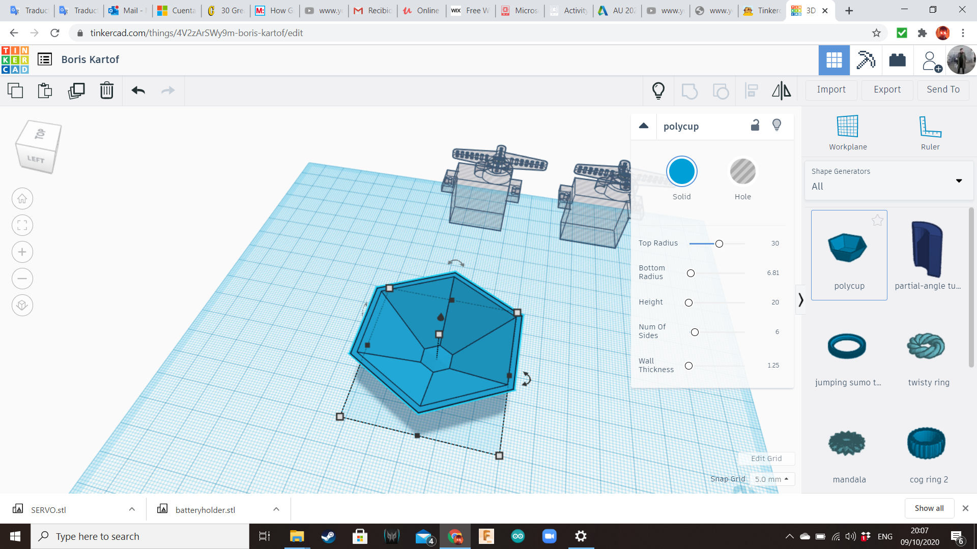
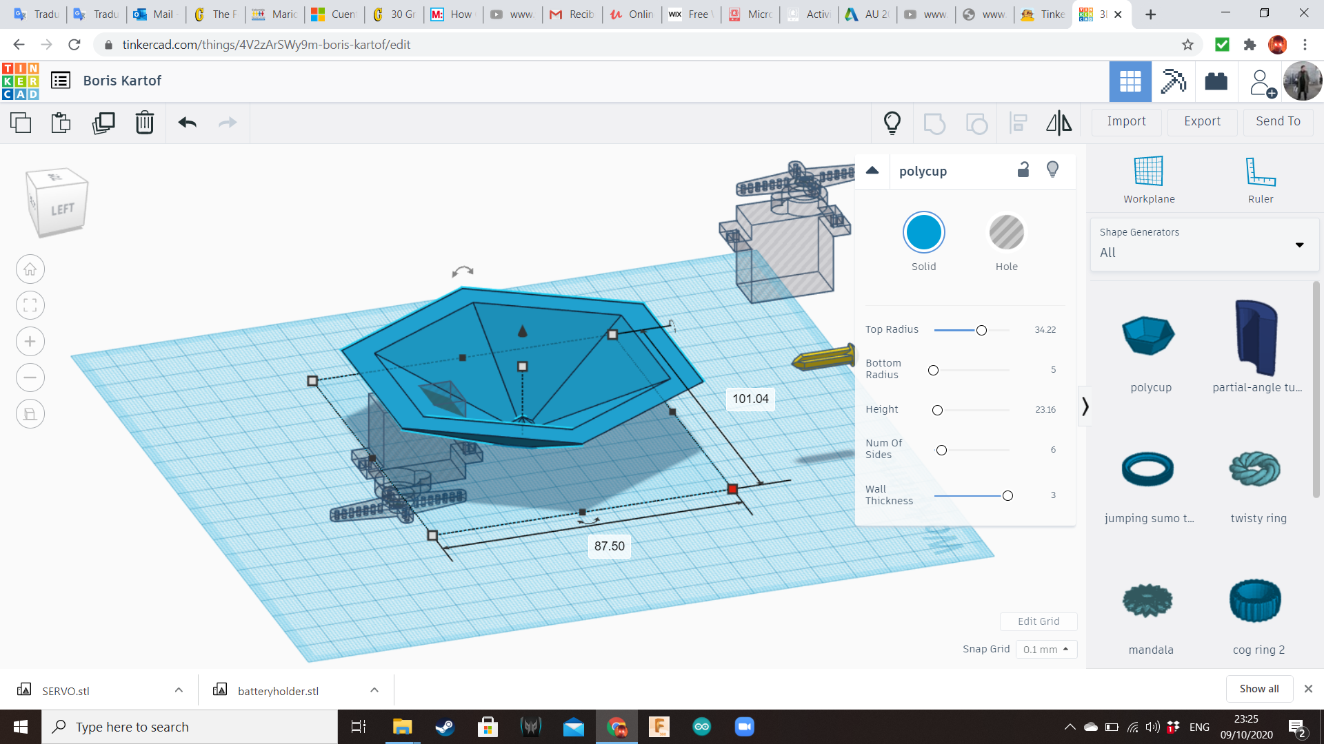
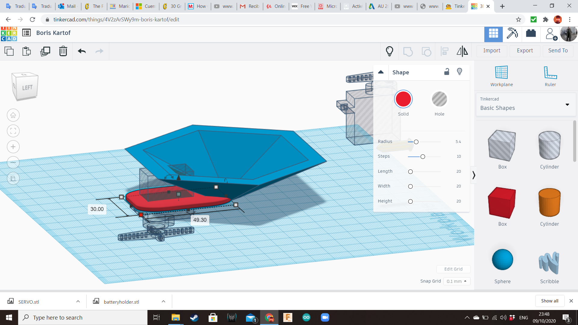
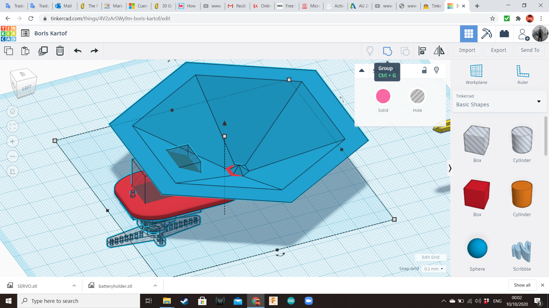
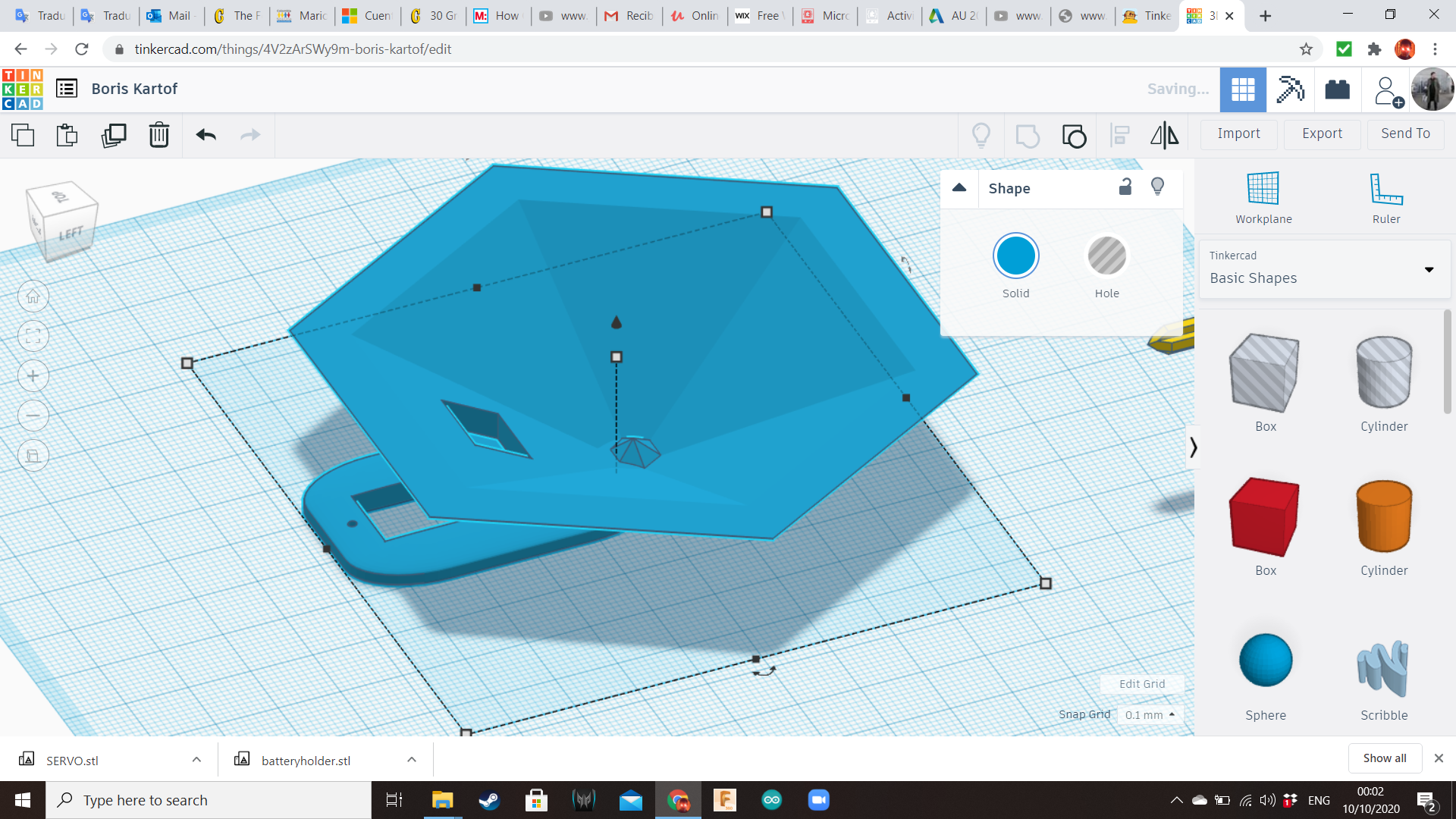
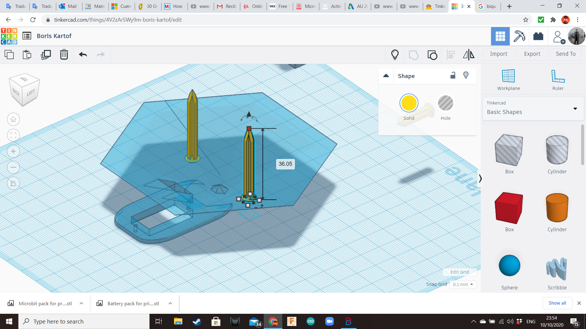
Now it's time for the servo. Export it as a STL and import it again with 105% scale. Transform it into a hole and duplicate it. One servo hole will be for the base where we will place the potato. We will use later the other servo hole, for the legs.
Bring a Polycup from the Shape Generators Library and a box from the Basic Shapes. Turn the servo hole with the axle facing down. Add two cylindrical holes in the positions where the screws must be located to fasten the servo. Now, group all the shapes.
Add two spiked on top, to attach the potato.
Back Legs Socket
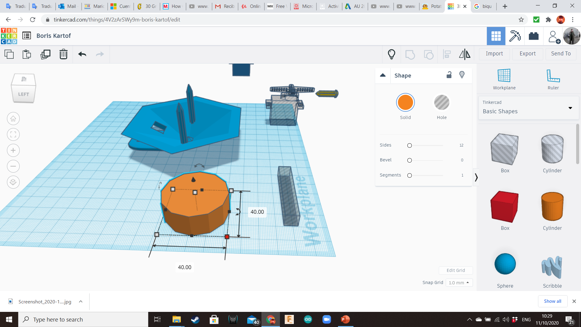
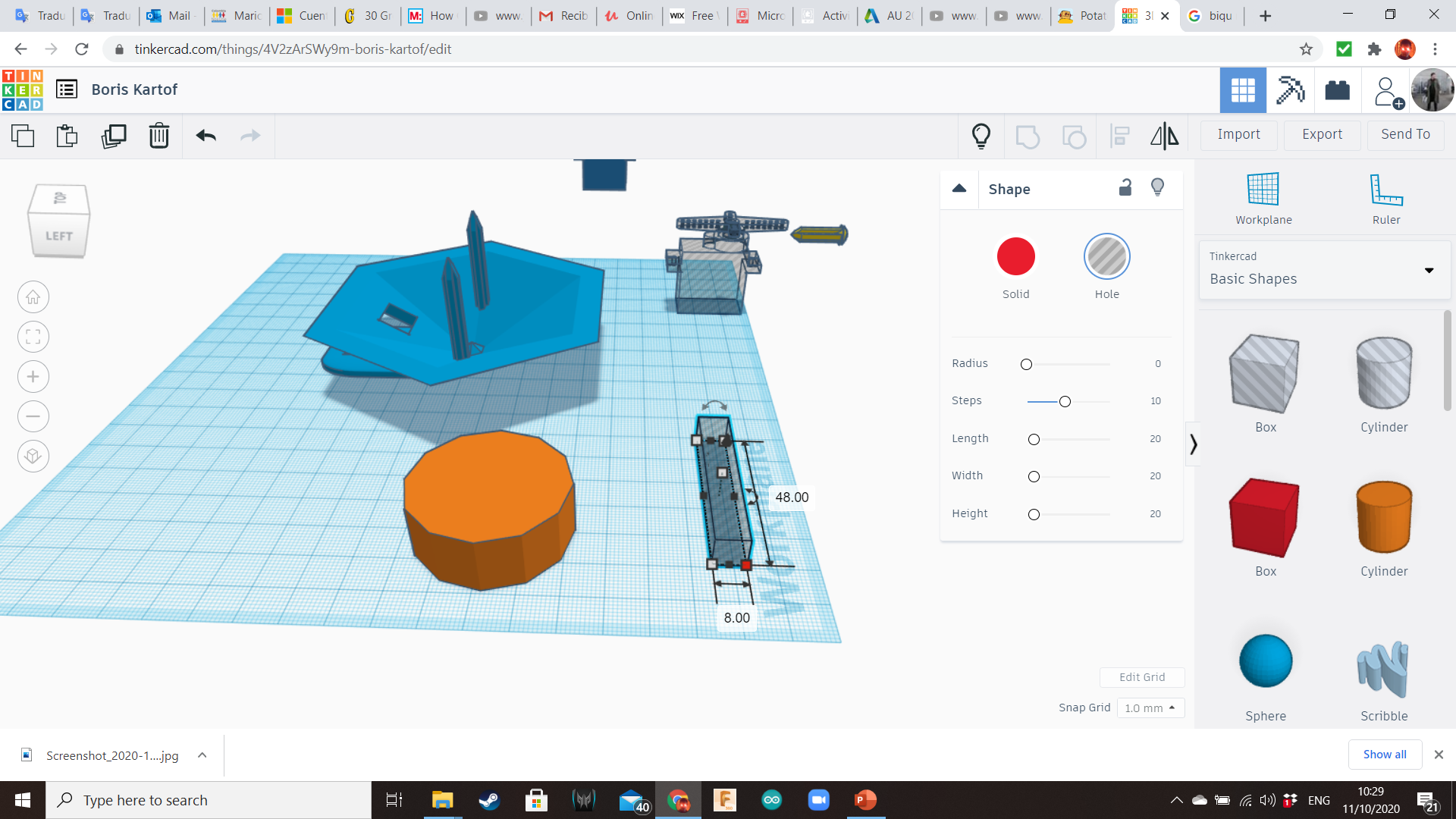
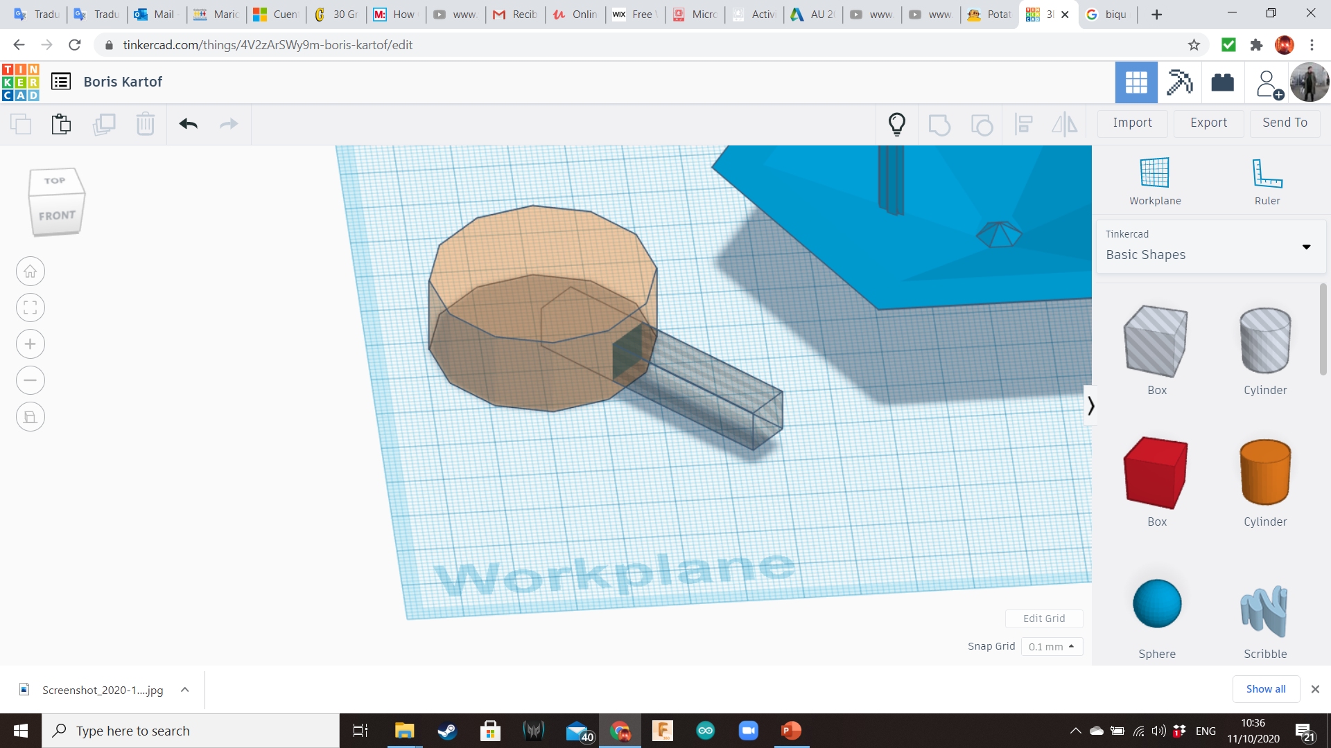
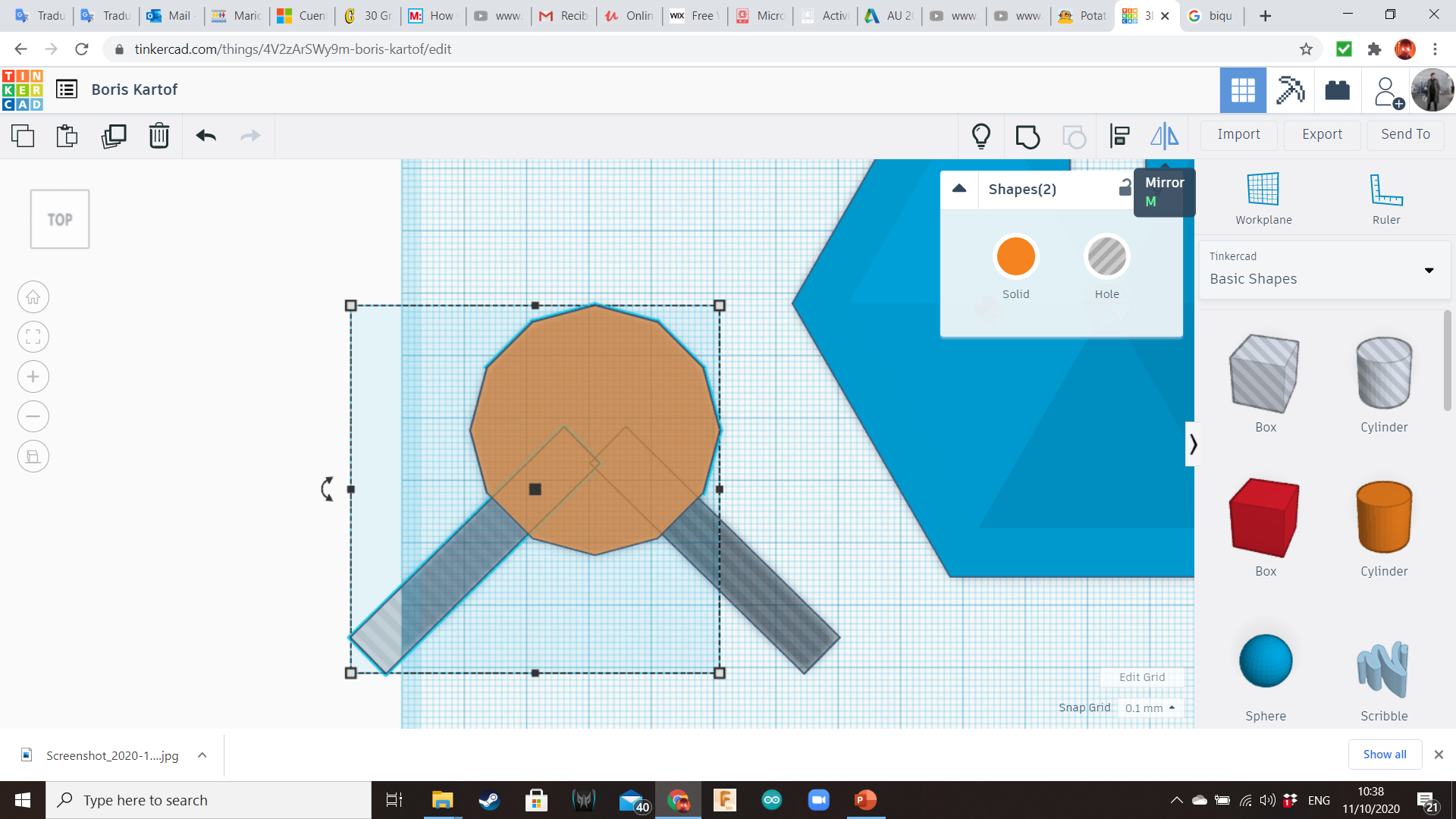
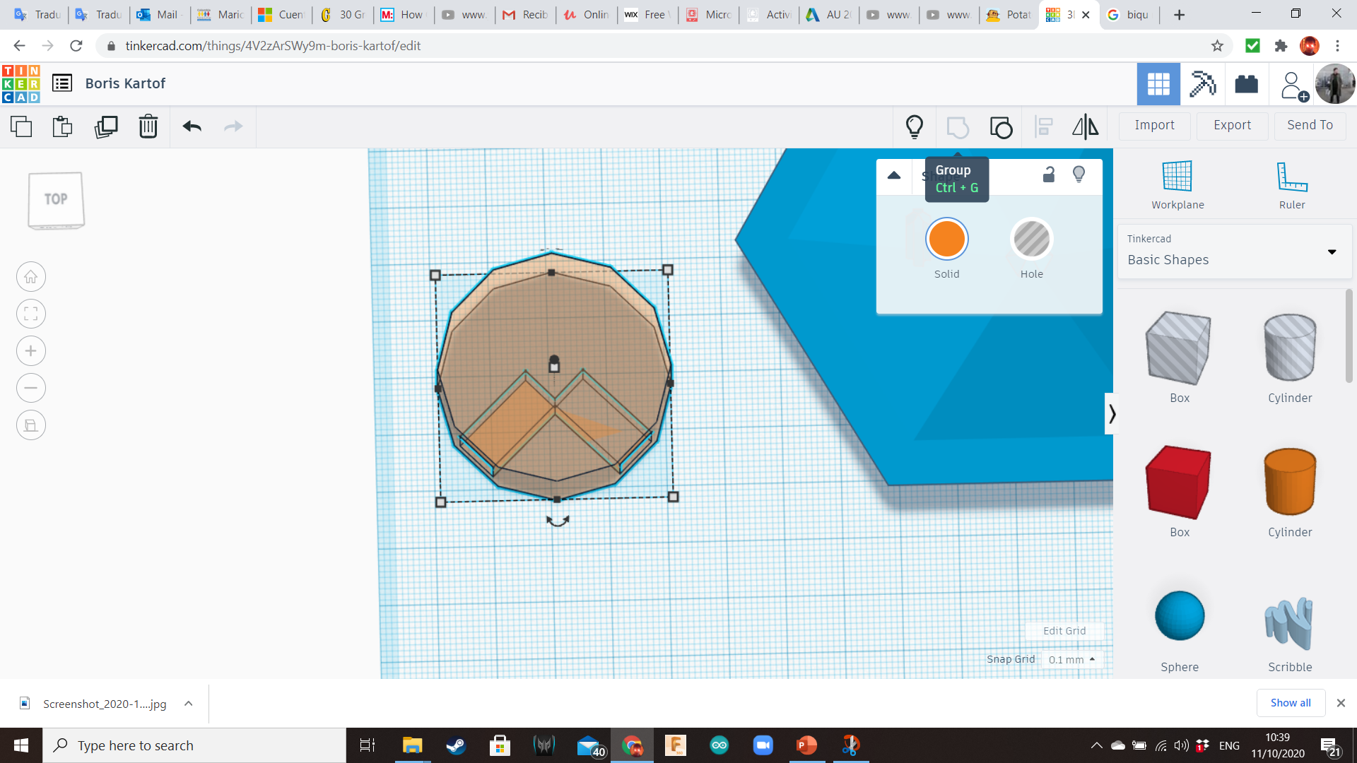
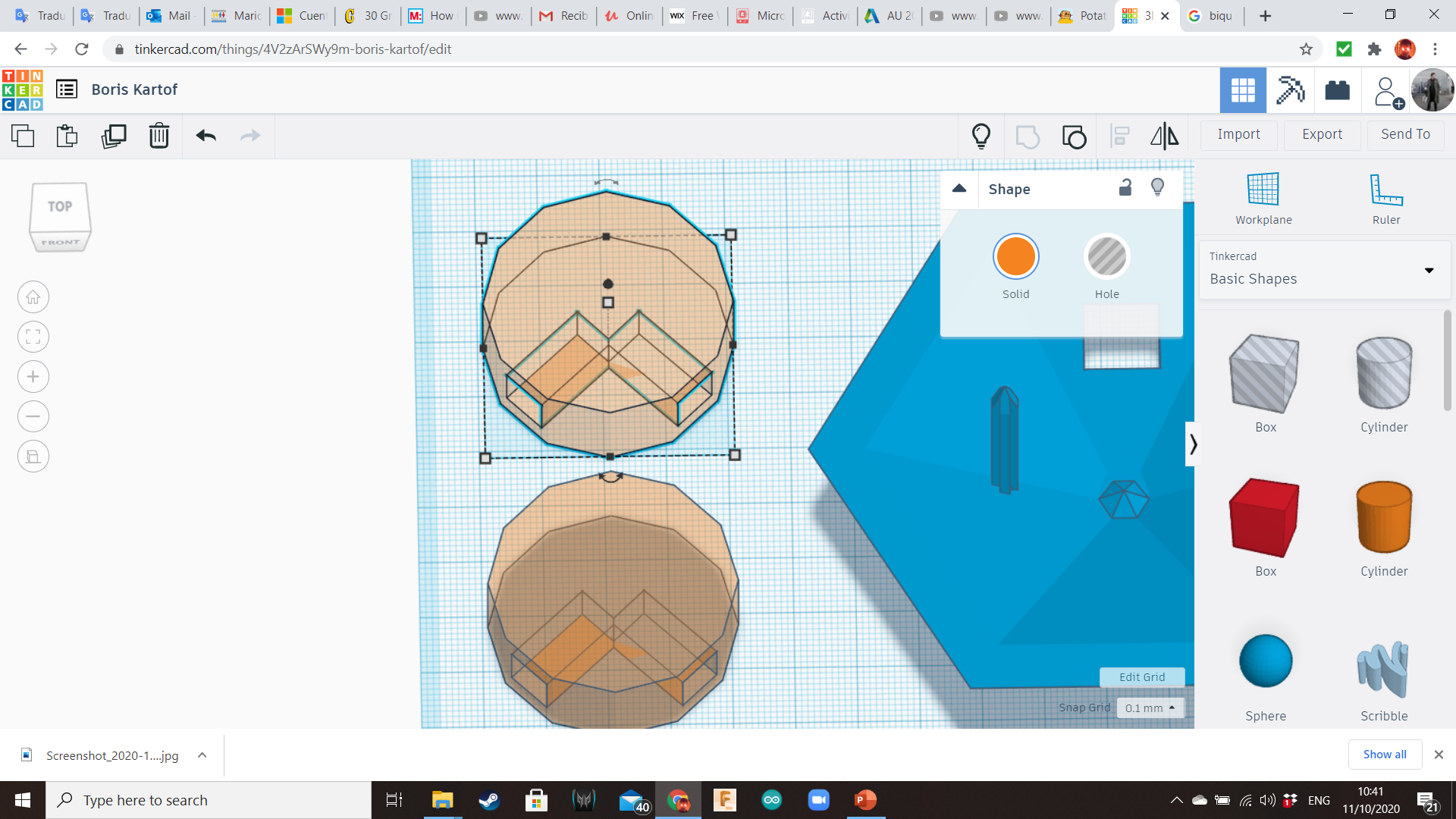
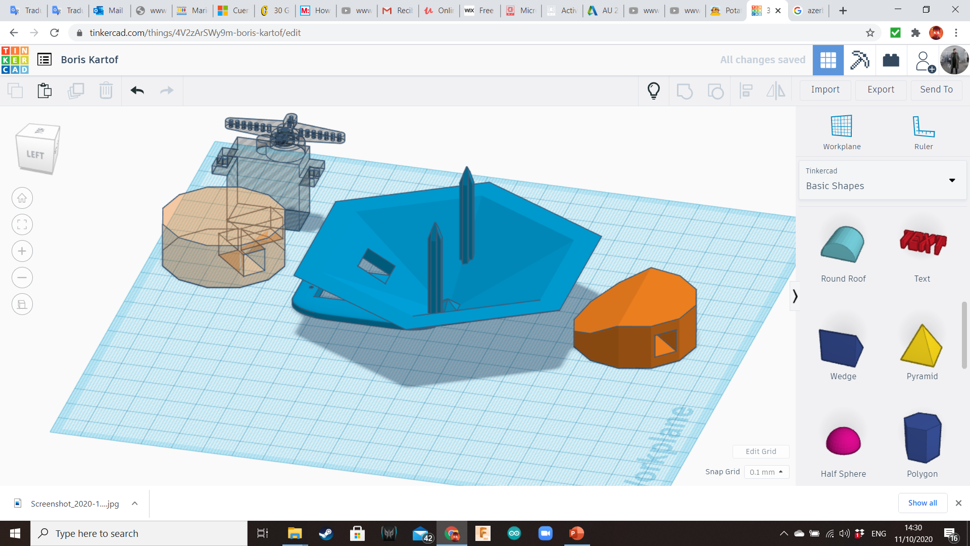
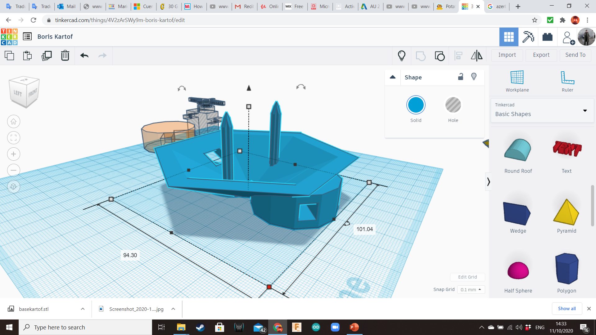
Bring a 12-sided cylinder and insert two long hole boxes of 4mm x 4mm of front, perpendicular one from the other. Group the shapes. The legs will be inserted on these holes.
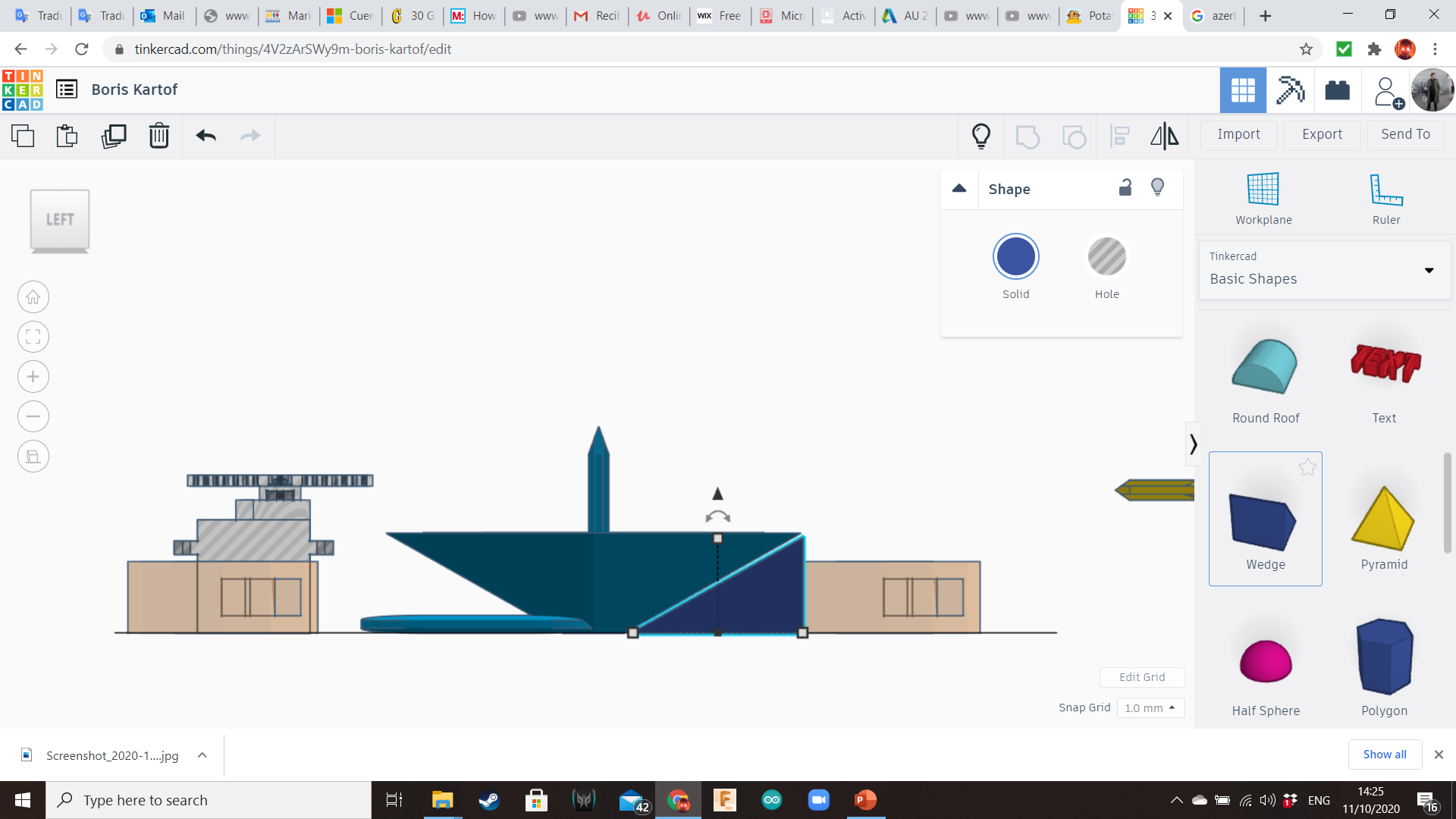
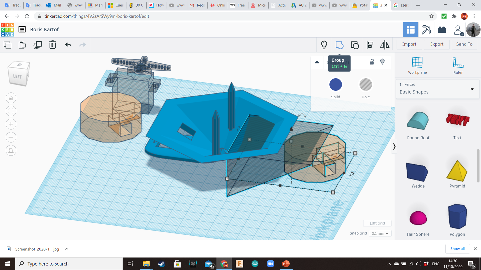
Duplicate this cylinder. Place one of them in the back of the base (opposite to the servo). To avoid bumpy shapes inside the base, you can use a Wedge hole (Basic Shapes Library). Keep the other cylinder for later.
Front Legs Socket (for Servo)
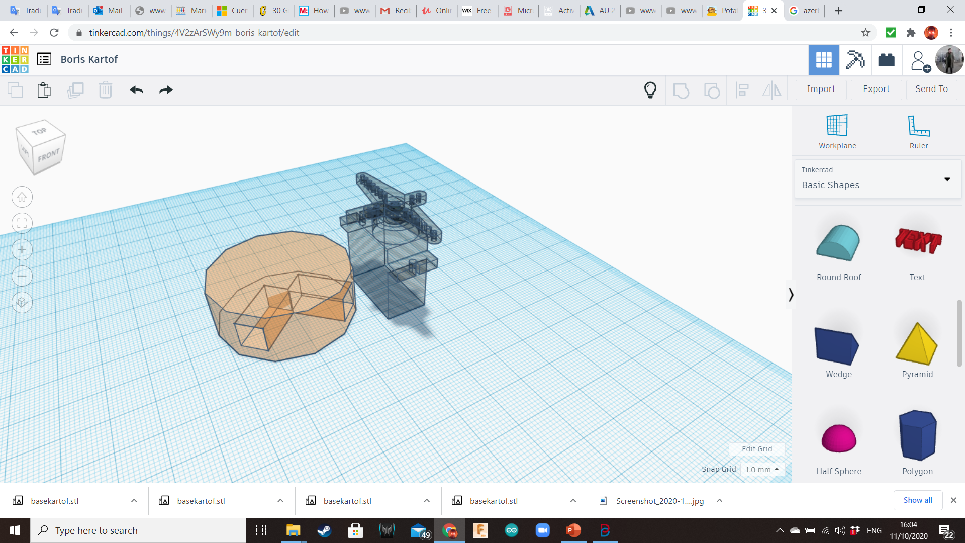
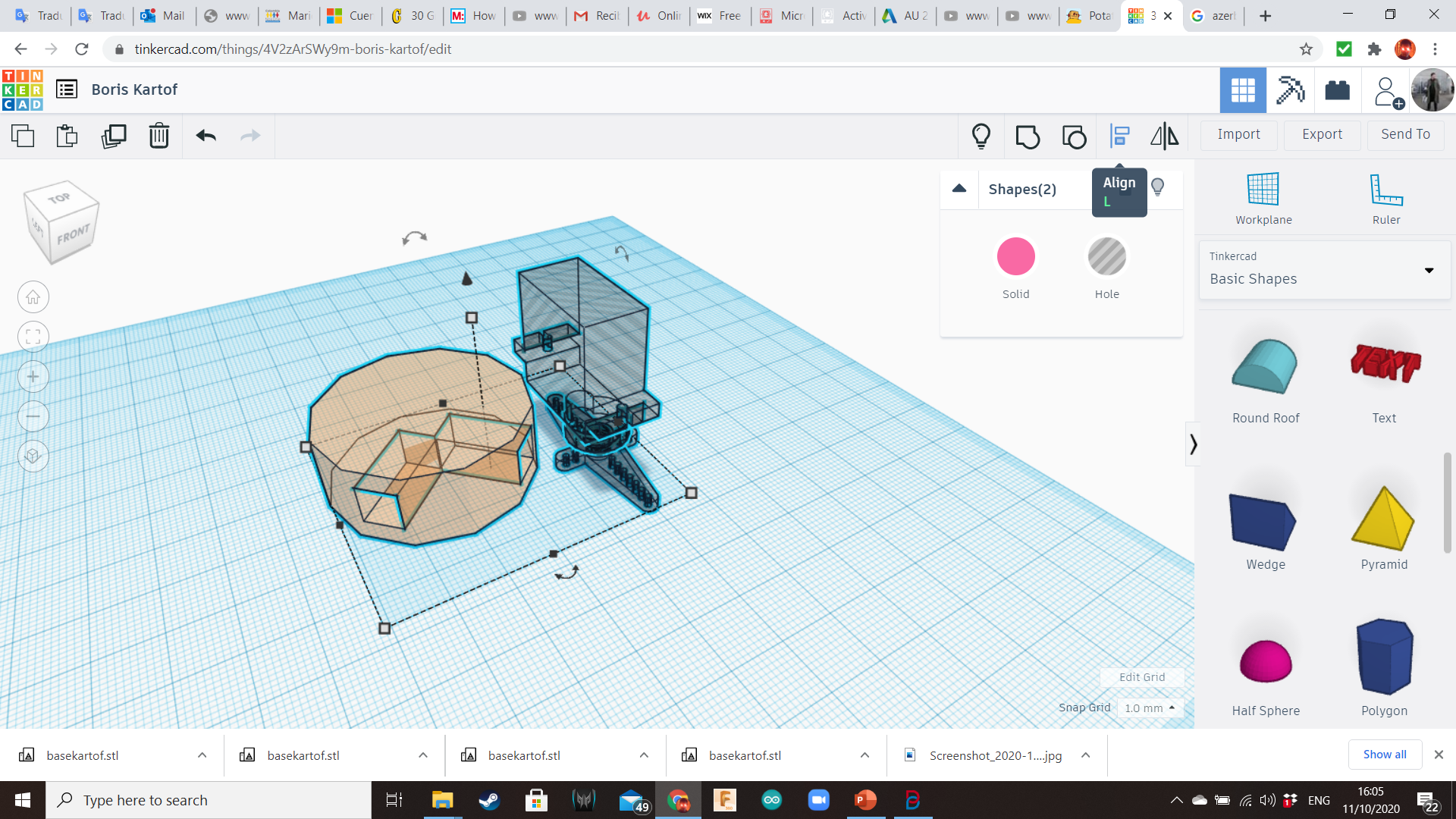
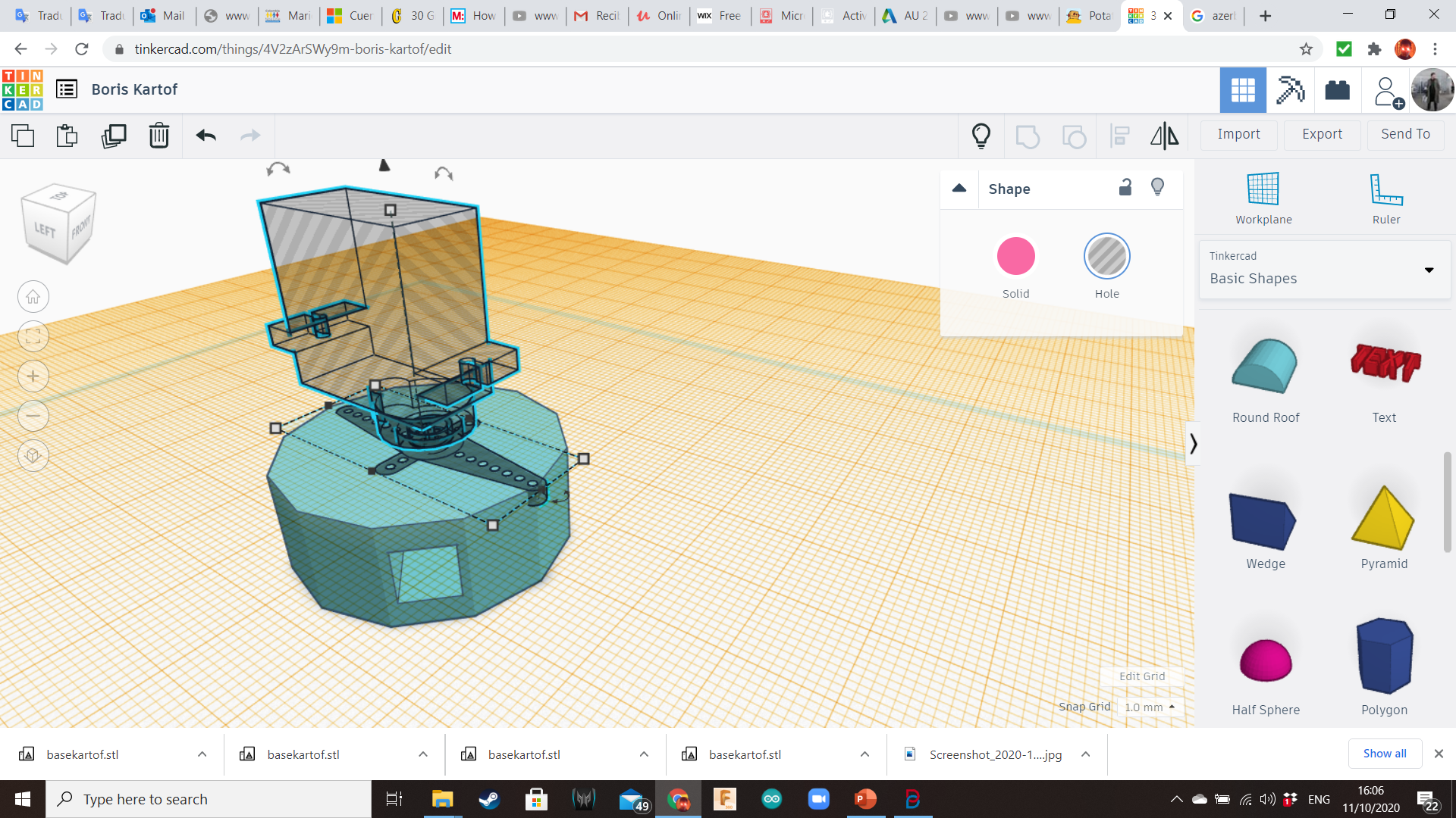
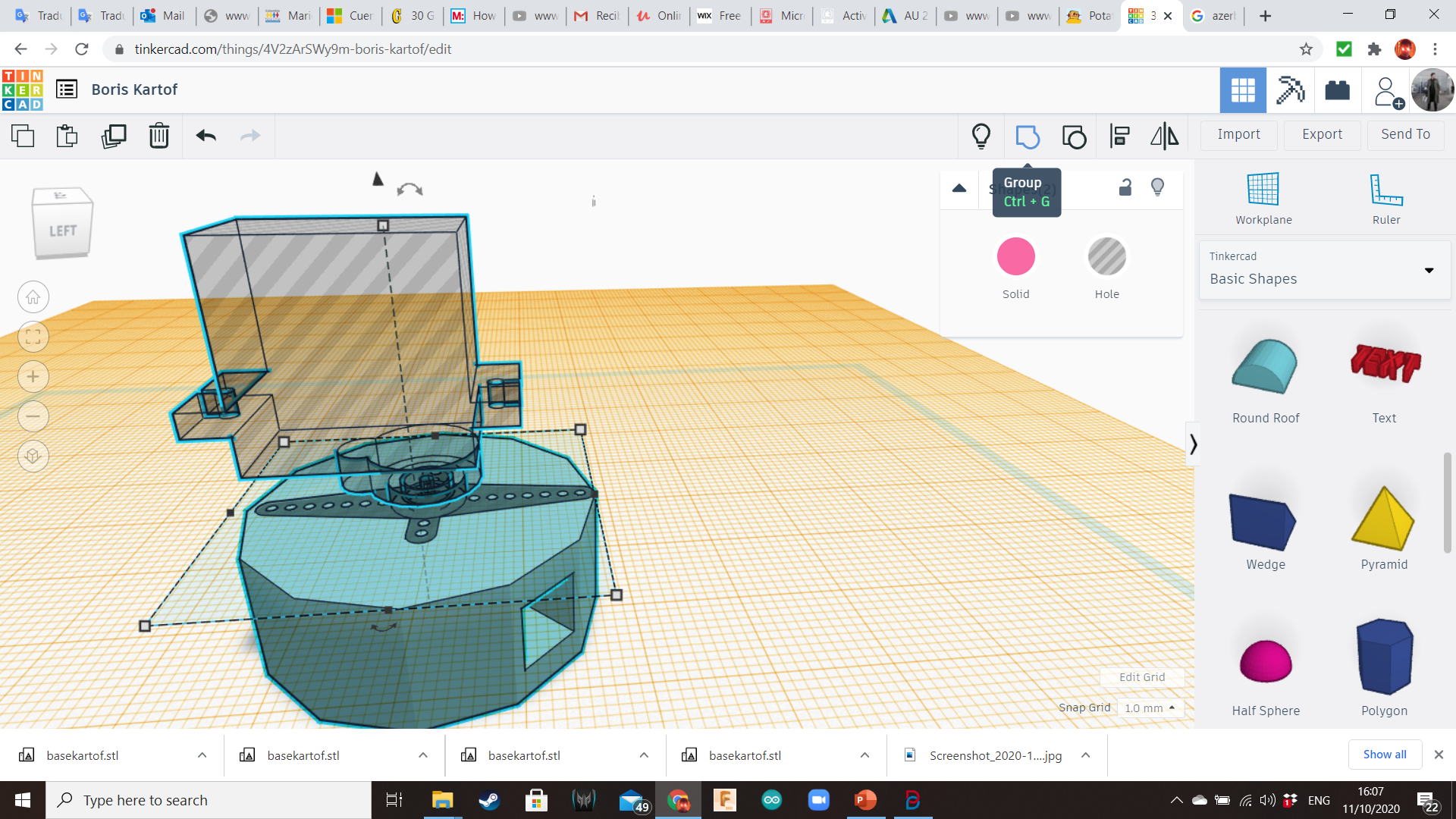
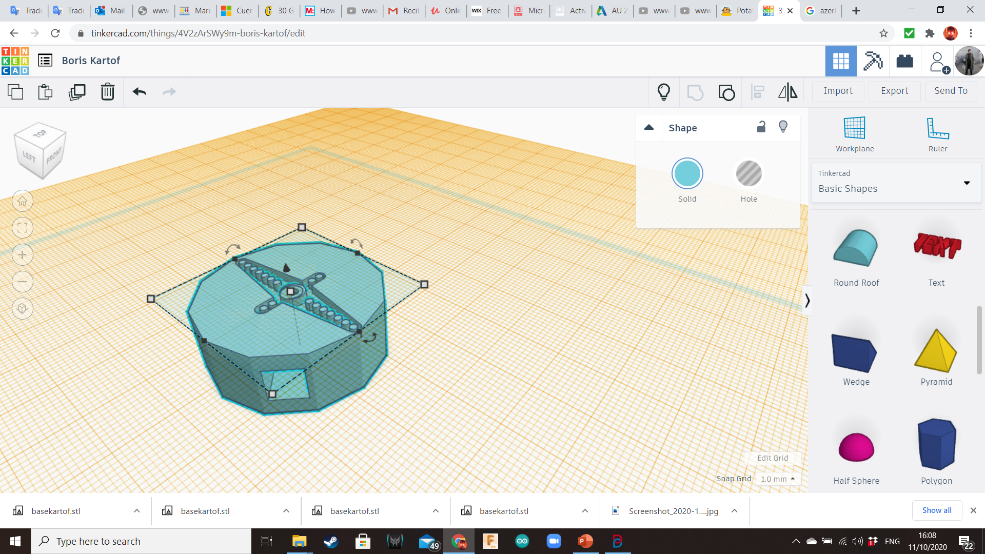
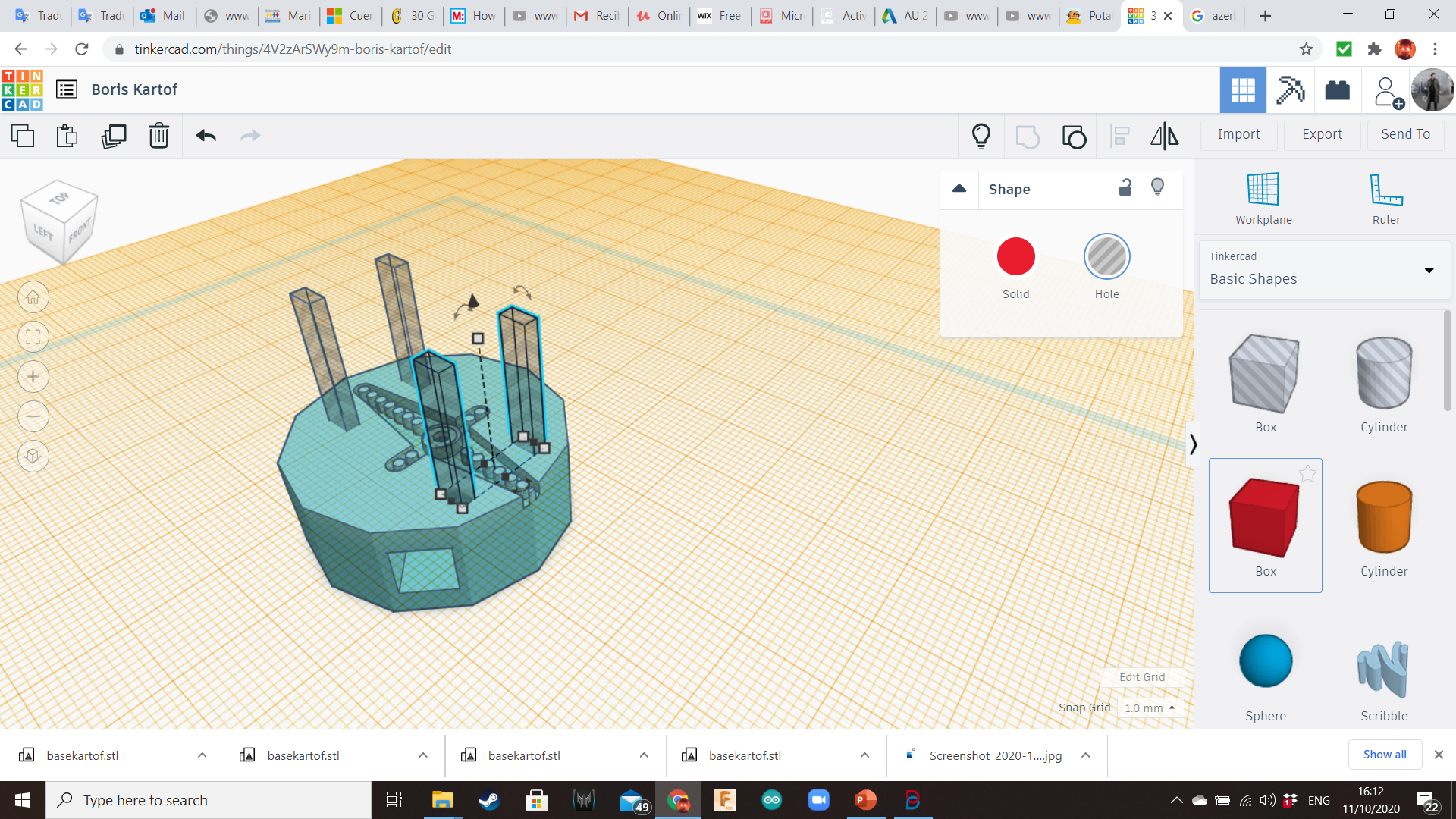
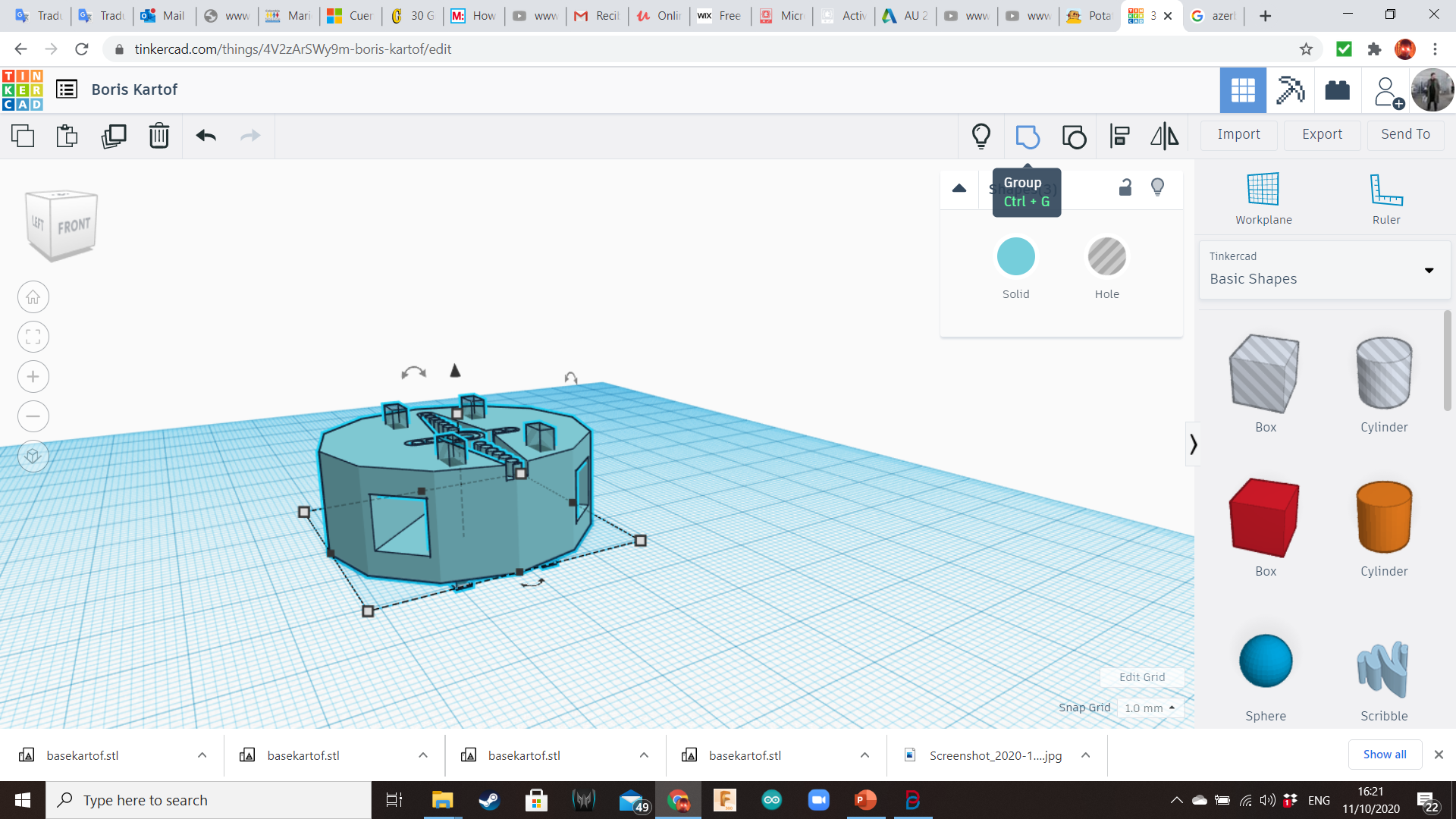
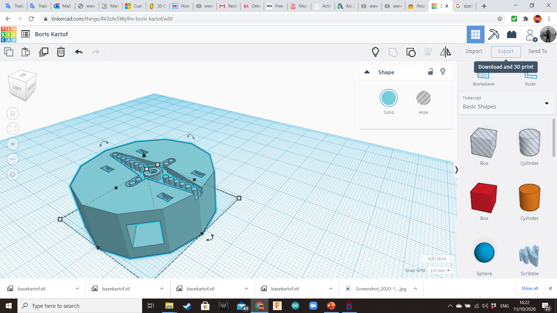
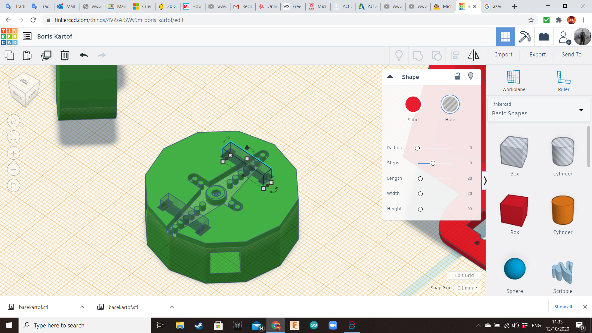
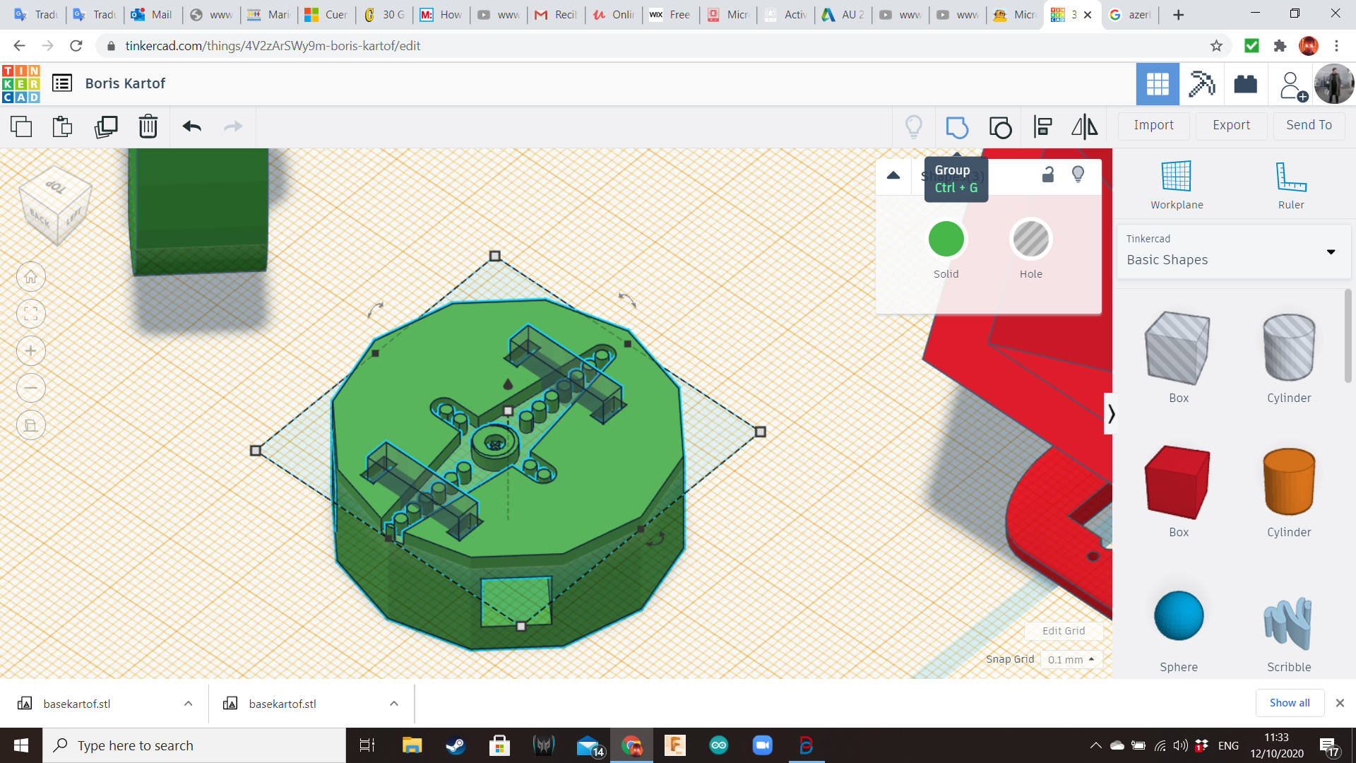
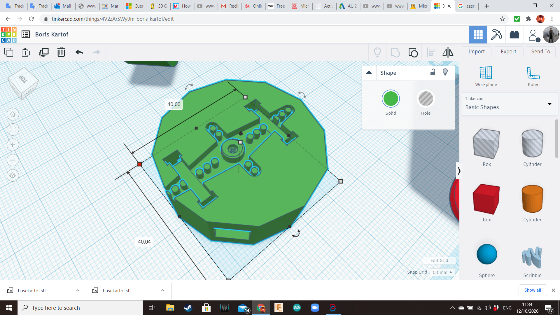
Take the available servo hole and the available cylinder, and group them, placing the servo's axle over the top of the cylinder. Also, create four small holes using boxes, so the axle's arms from the servo can be attached to this component using zipties.
Potato!
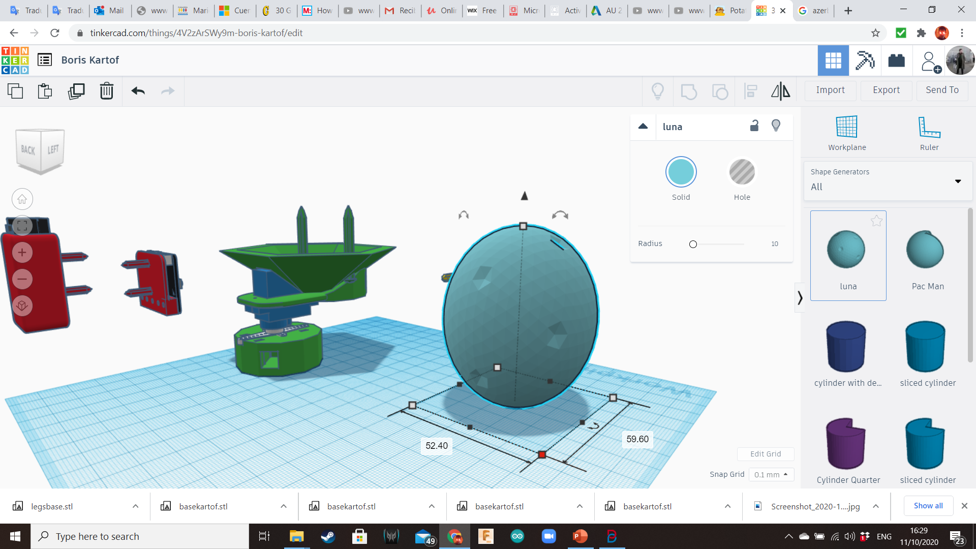
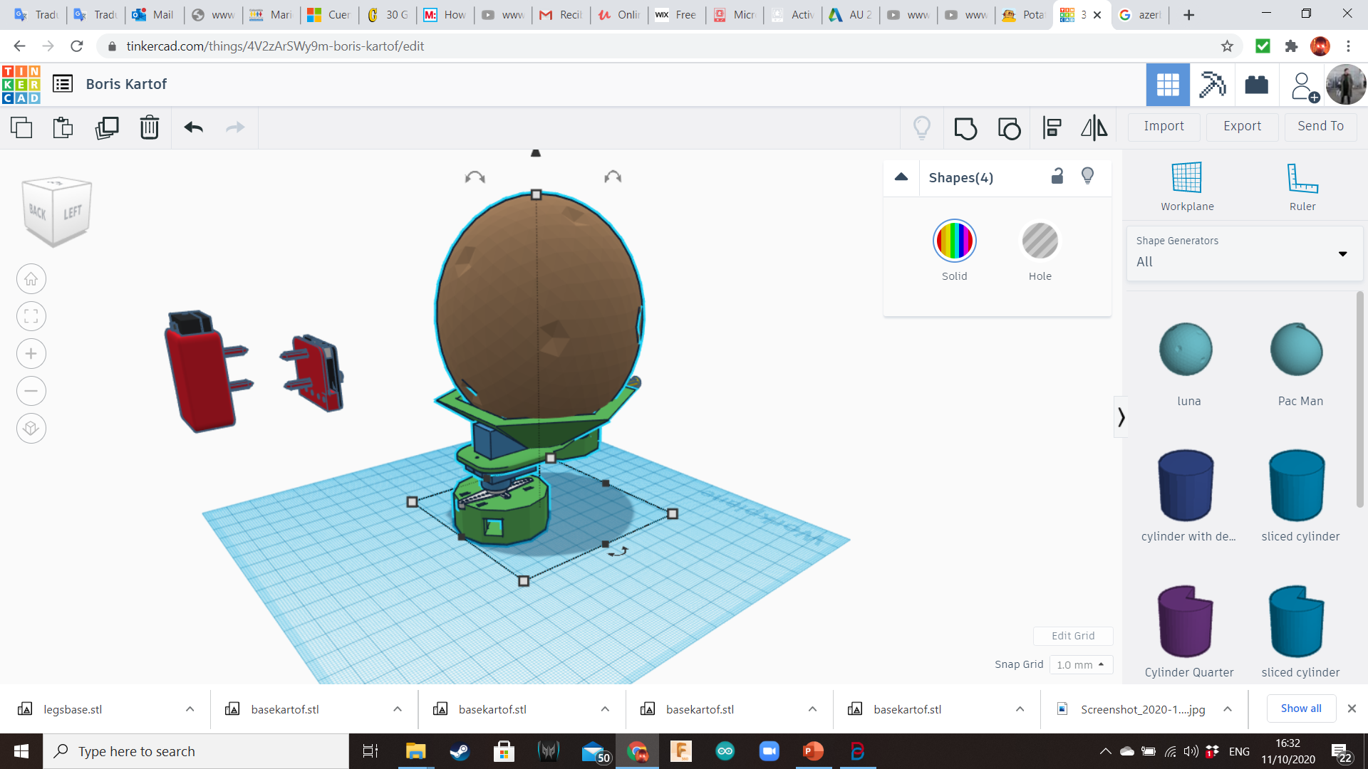
Bring a Luna from the Shape Generators Library, and transform it into a potato for reference.
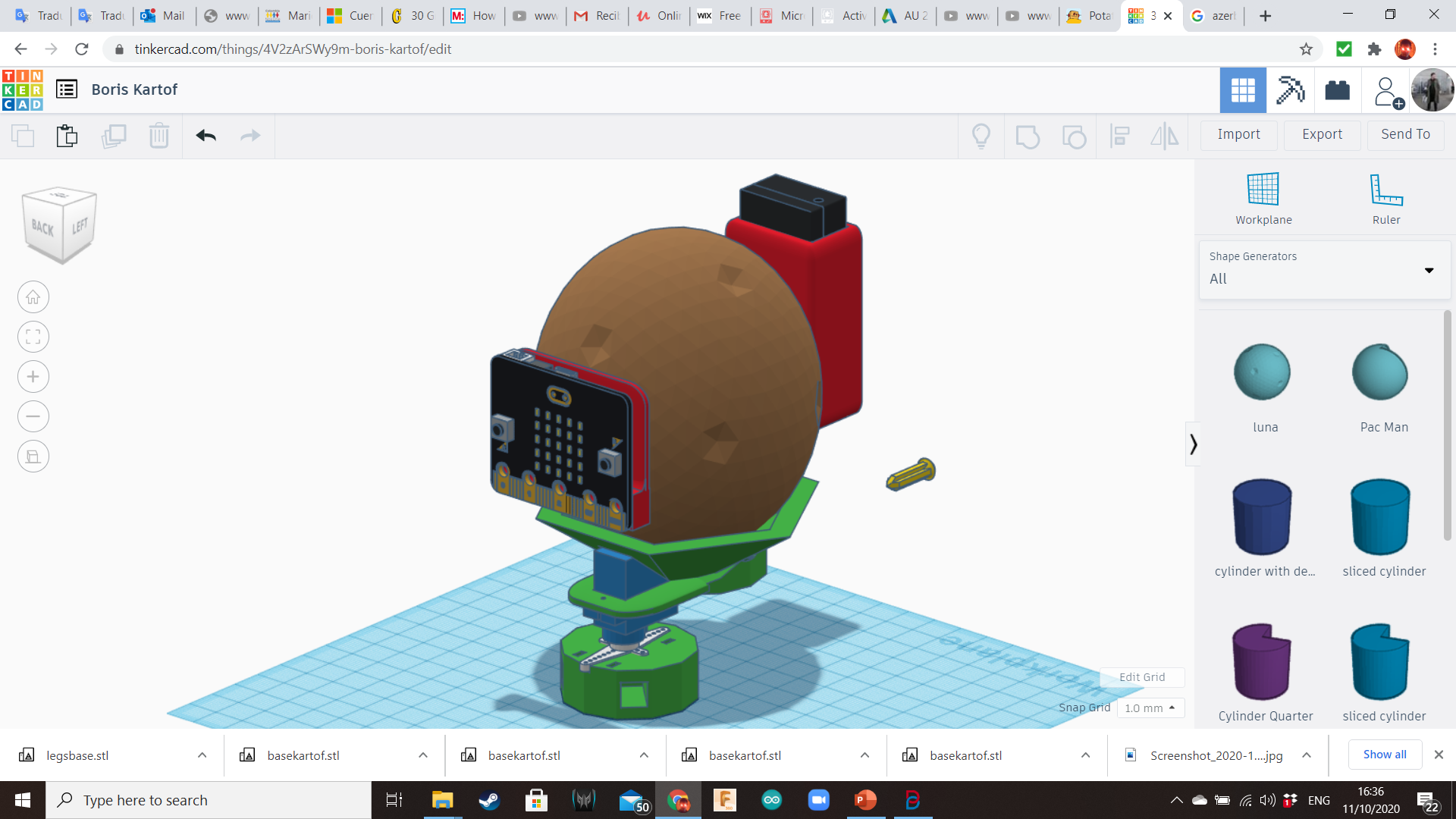
Place it over the base and insert the battery backpack and the Micro:bit plate on it.
Legs
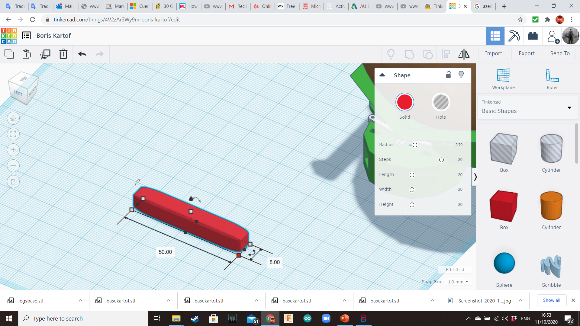
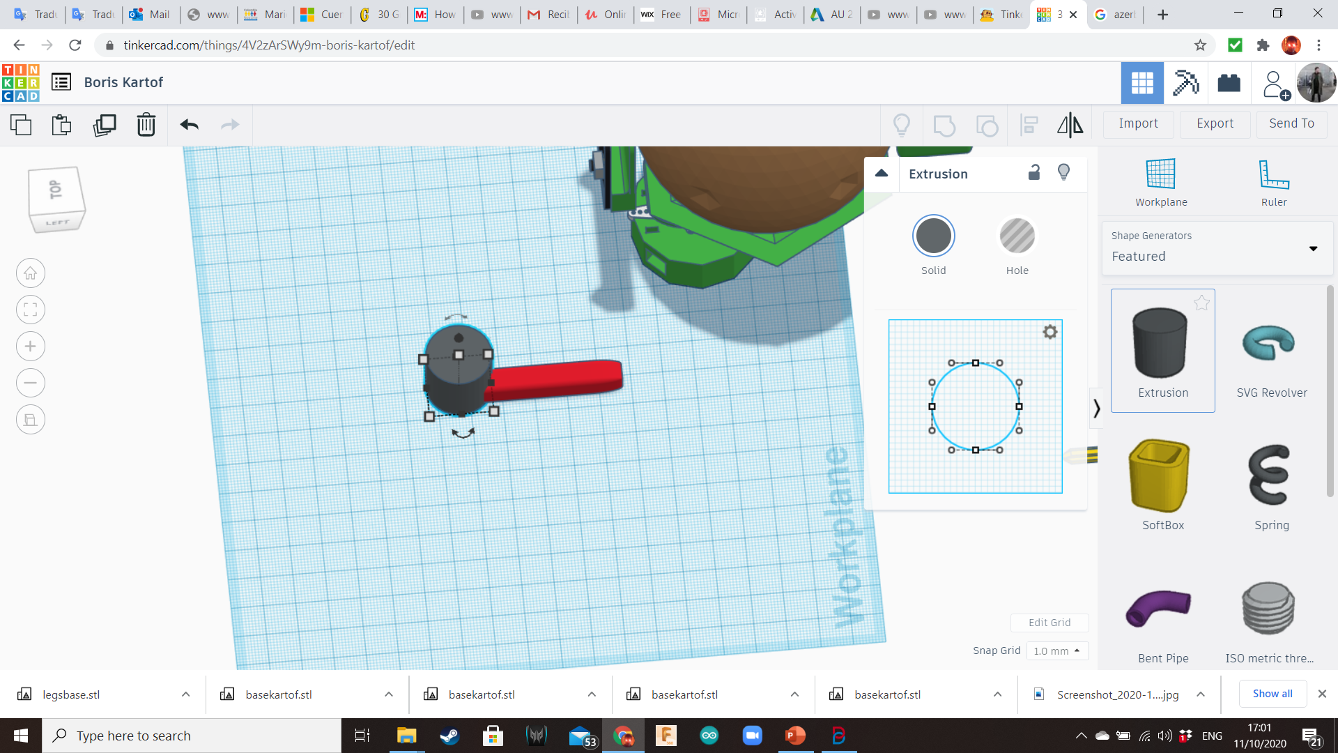
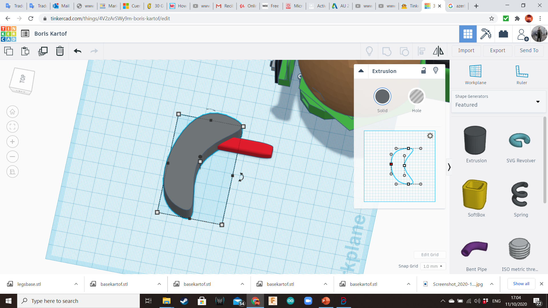
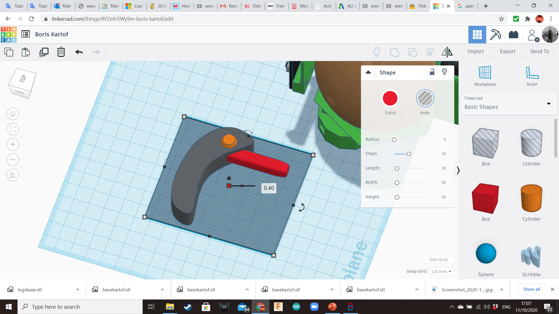
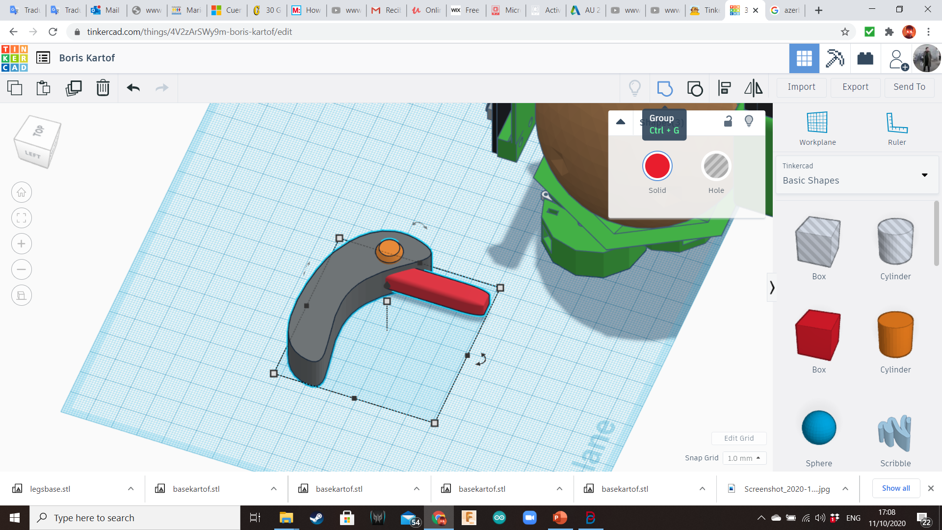
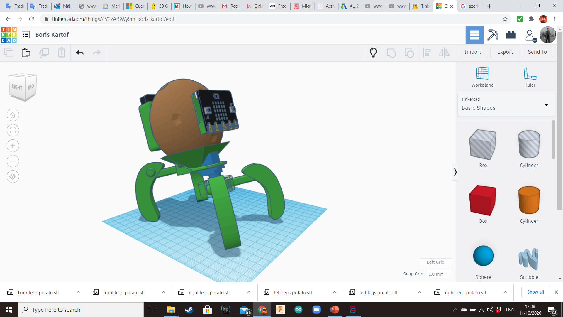
Create four legs using the Extrusion (Shape Generators Library - Featured), a long box of 8mm x 8mm of side, and a cylinder for decoration. Duplicate it and mirror them. Insert the legs in the sockets.
Slicing Settings
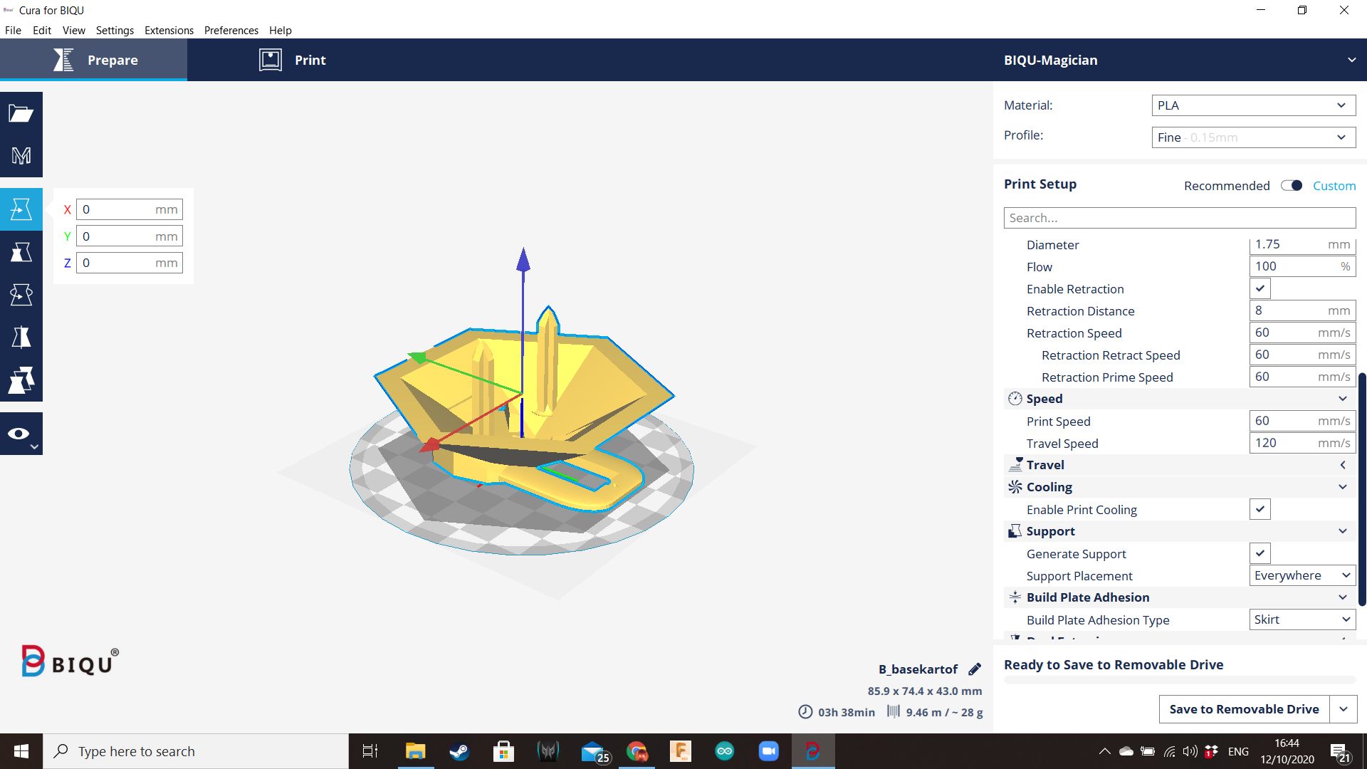
Export each component as an STL file, and send them to the slicer.
If you have a bigger 3D printer, probably you can print all the pieces at the same time and you can try different printing settings. But I have a small Biqu Magician. I used the following settings:
- Supports: enabled
- Retraction distance: 3 mm
- Retraction retract speed: 50 mm/sec
- Prime speed: 25 mm/sec
- Z hop when retracted: enabled
- Max Z speed: 120 mm/s
- Z hop height: 1 mm
- Travel speed: 200 mm/s
- Layer height: 0.15 mm
- Print temp initial layer: 200 degrees (for good bonding)
- Main Printing Temperature: 180 degrees for main print temp
- Overhang: 30 degrees
- Brim: enabled
- Support Pattern: Grid
- All the other settings: default
- Material: PLA
Improvements
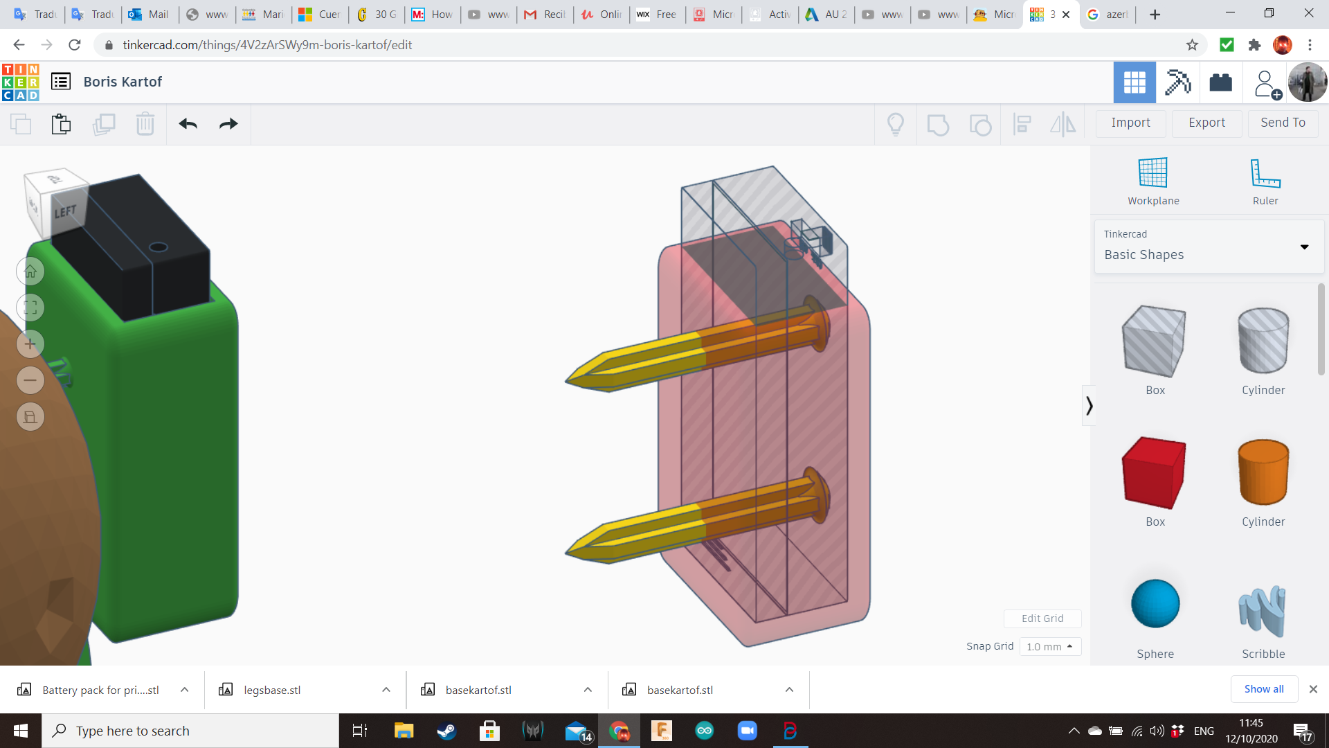
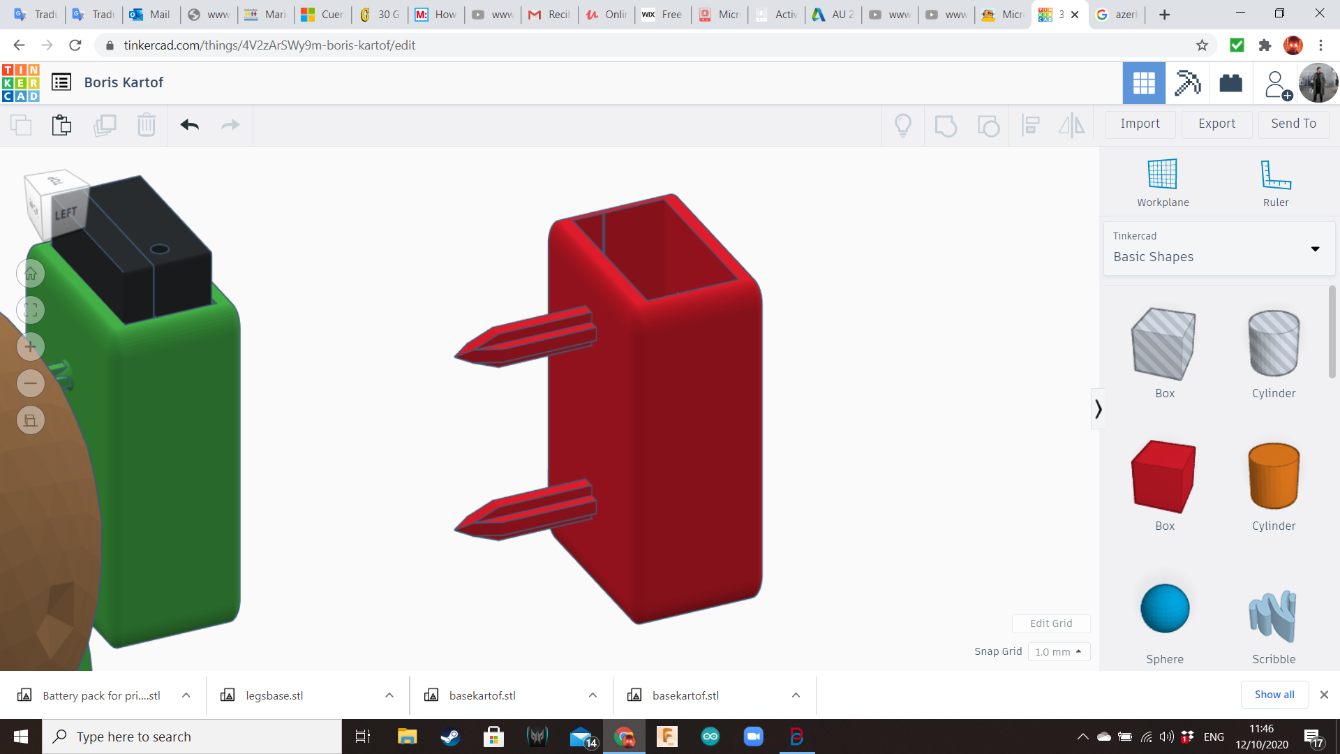
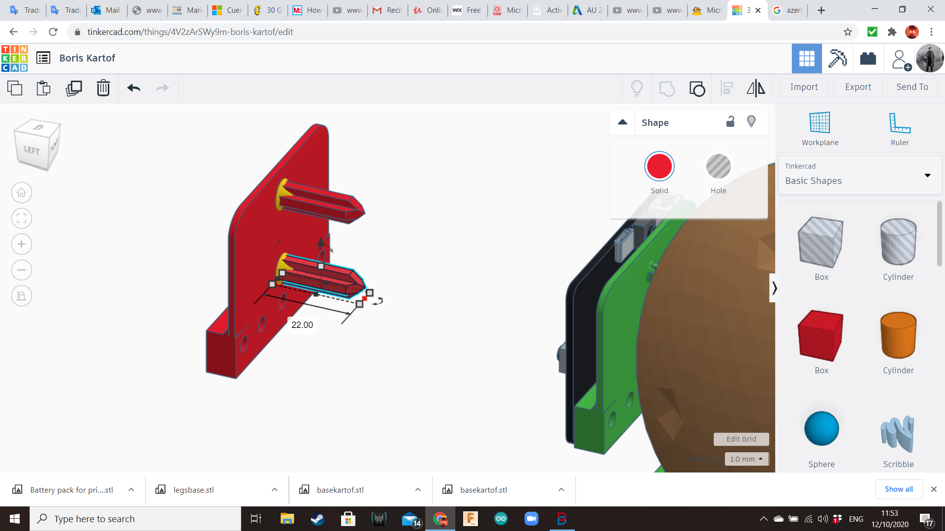
After the first tests I realize the spikes are too fragile, so I redesigned them so they can be sturdier and resist the forces acting over them when the pieces are inserted in the potato.
Coding
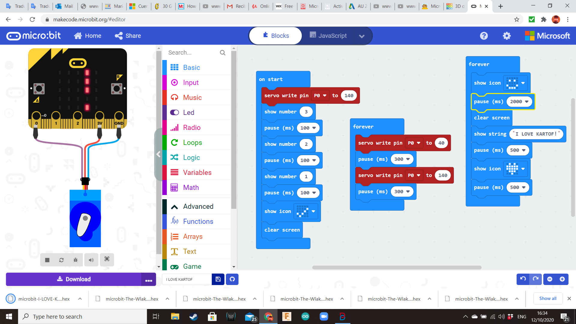
Open Makecode In your computer and click in “New Project”.
Click the word "untitled" and rename your project "I Love Kartof" (or any silly name of your preference). Micro:bit has three digital pins in its basic form: 0, 1 and 2. Also, there are a 3V pin and a GND (ground) pin to power some special electronic components. The servomotor will be connected to the pins 3V and GND to power it, and to pin 0 to control it.
Elaborate the program displayed in the photo. It has basically three loops: "On Start" will place the servo in the starting position and start a countdown. The first "Forever" will control the way the robot walks, and the second "Forever" will control the display.
Press the “Download” button to download your code as a .hex file. When you download the code, it gets compiled from Javascript into ones and zeros that the Micro:bit can store and execute. You can find the code in the “download” folder of your computer. Drag the downloaded code over to your Micro:bit, just like dragging and dropping a file to an external drive or USB stick. You should see a yellow LED flashing next to your USB. This means the code is being transferred. When the LED finishes flashing, the program is fully downloaded.
Downloads
Physical Building: Micro:bit Cables
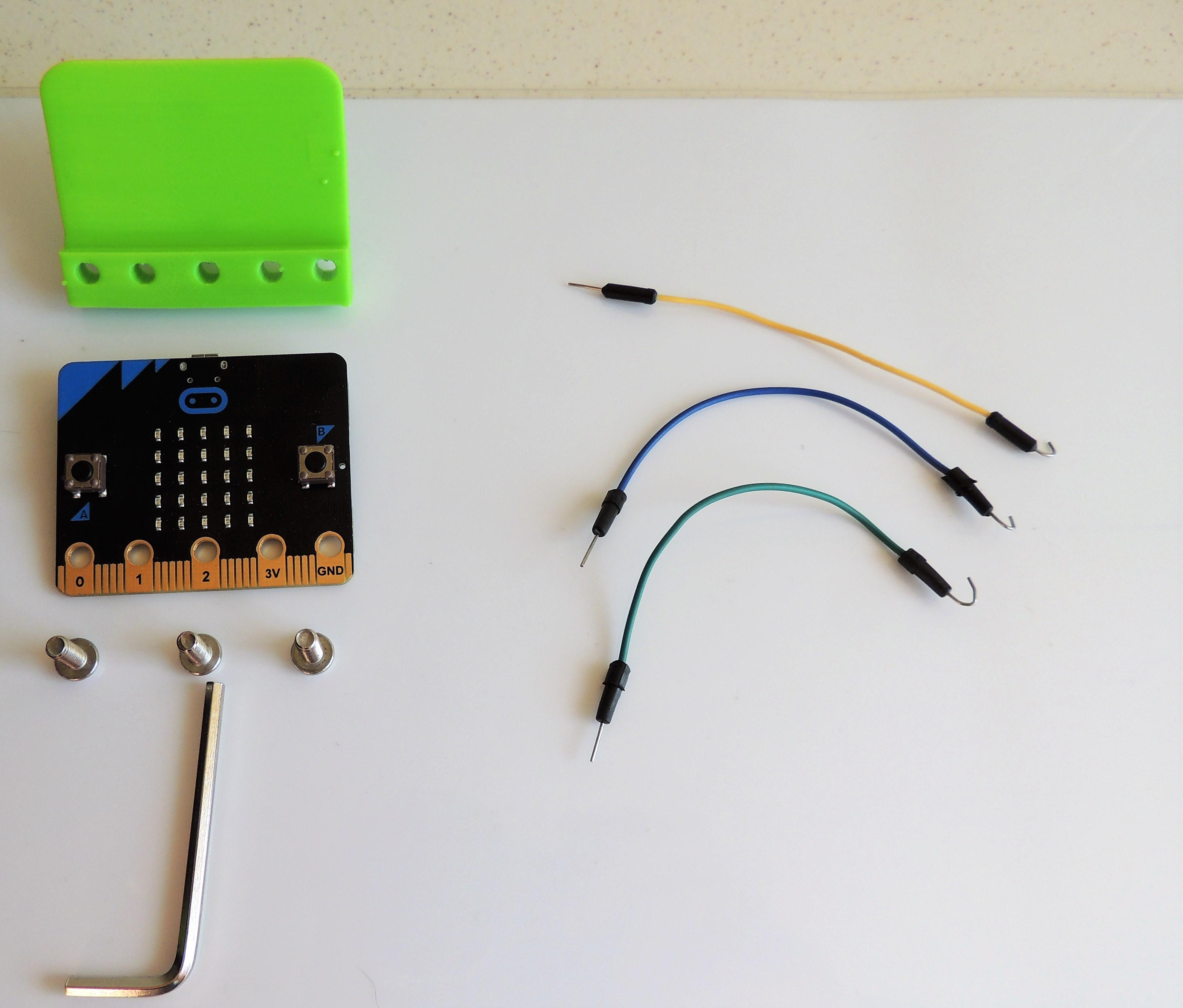
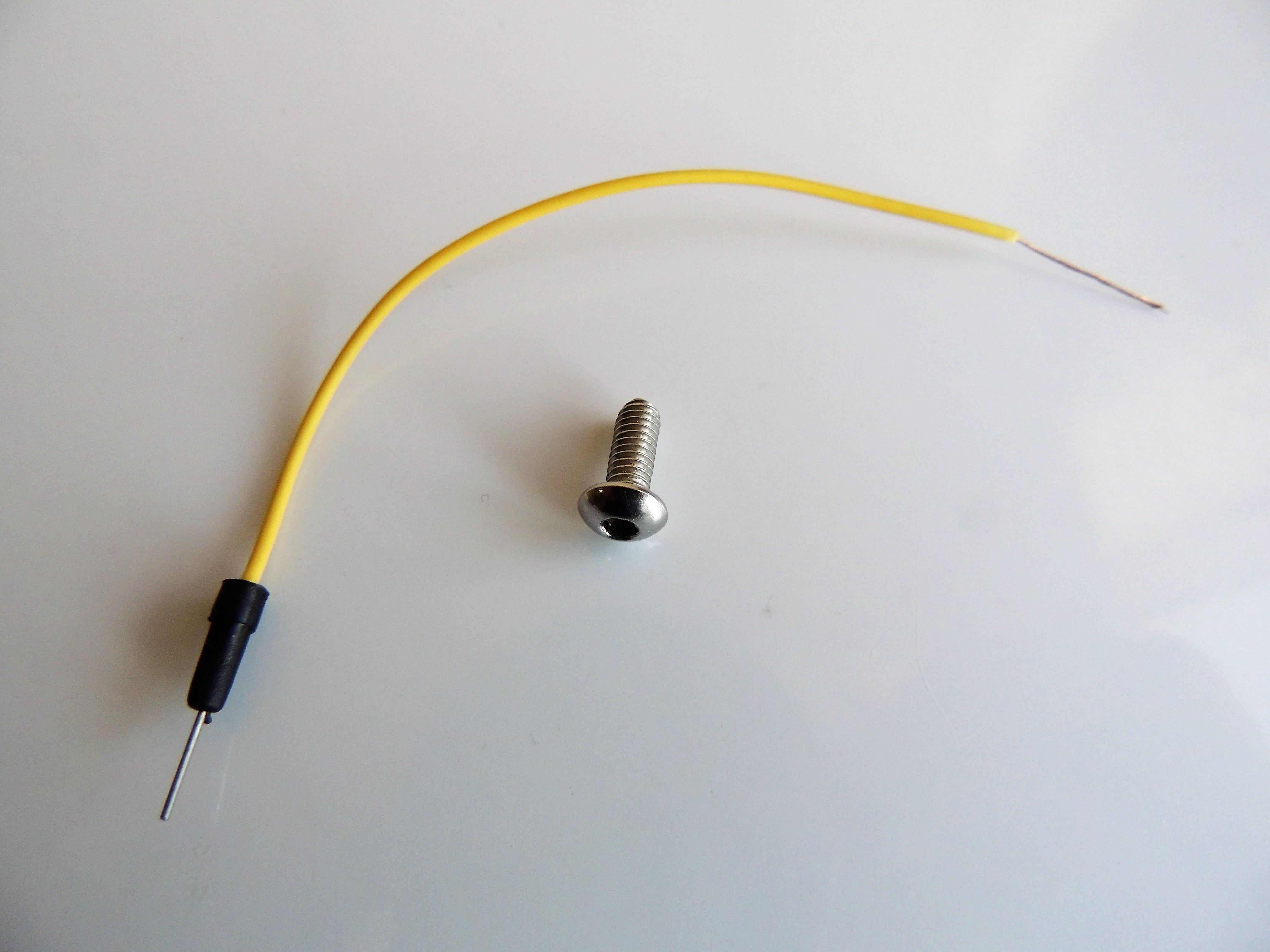
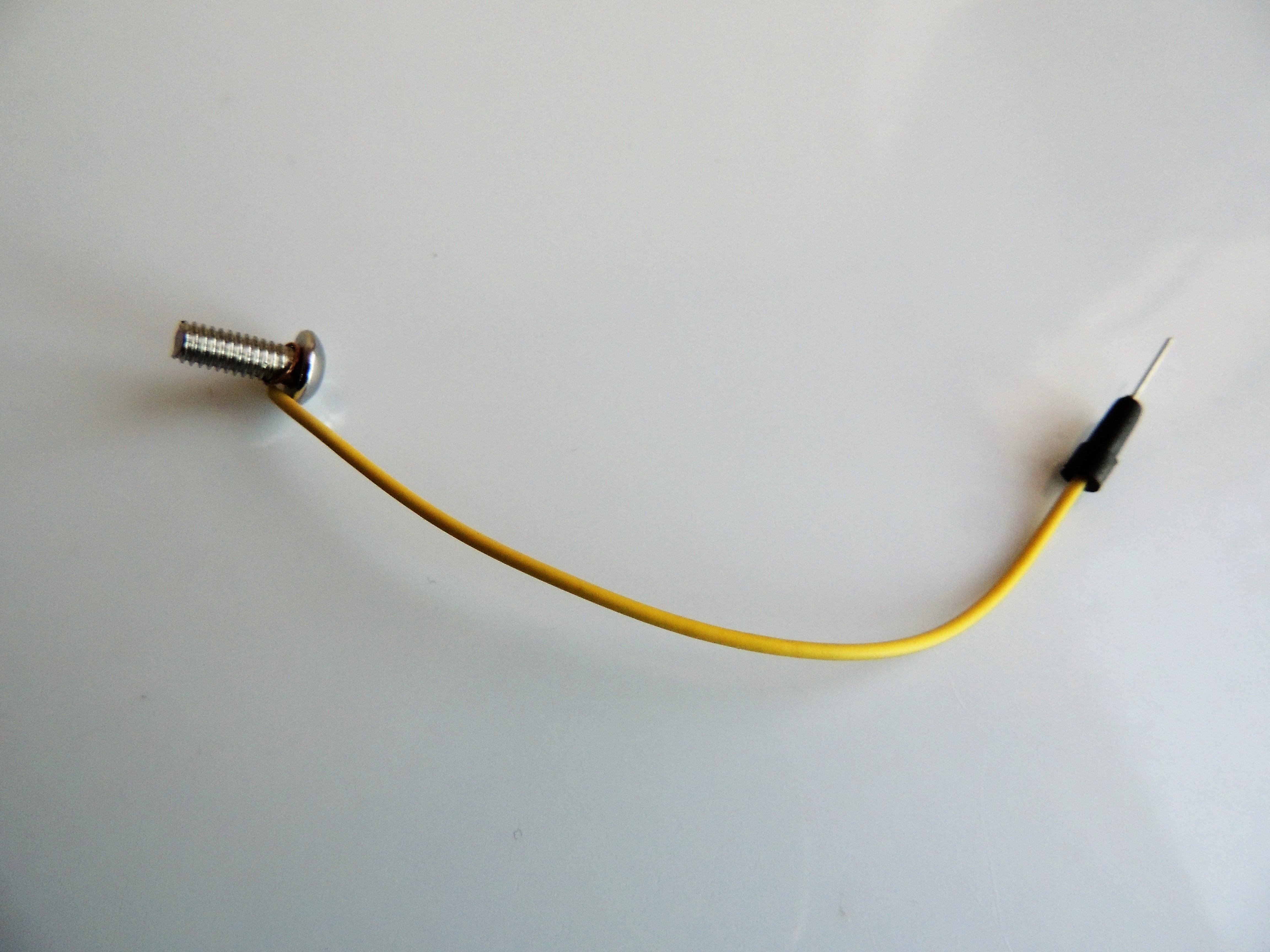
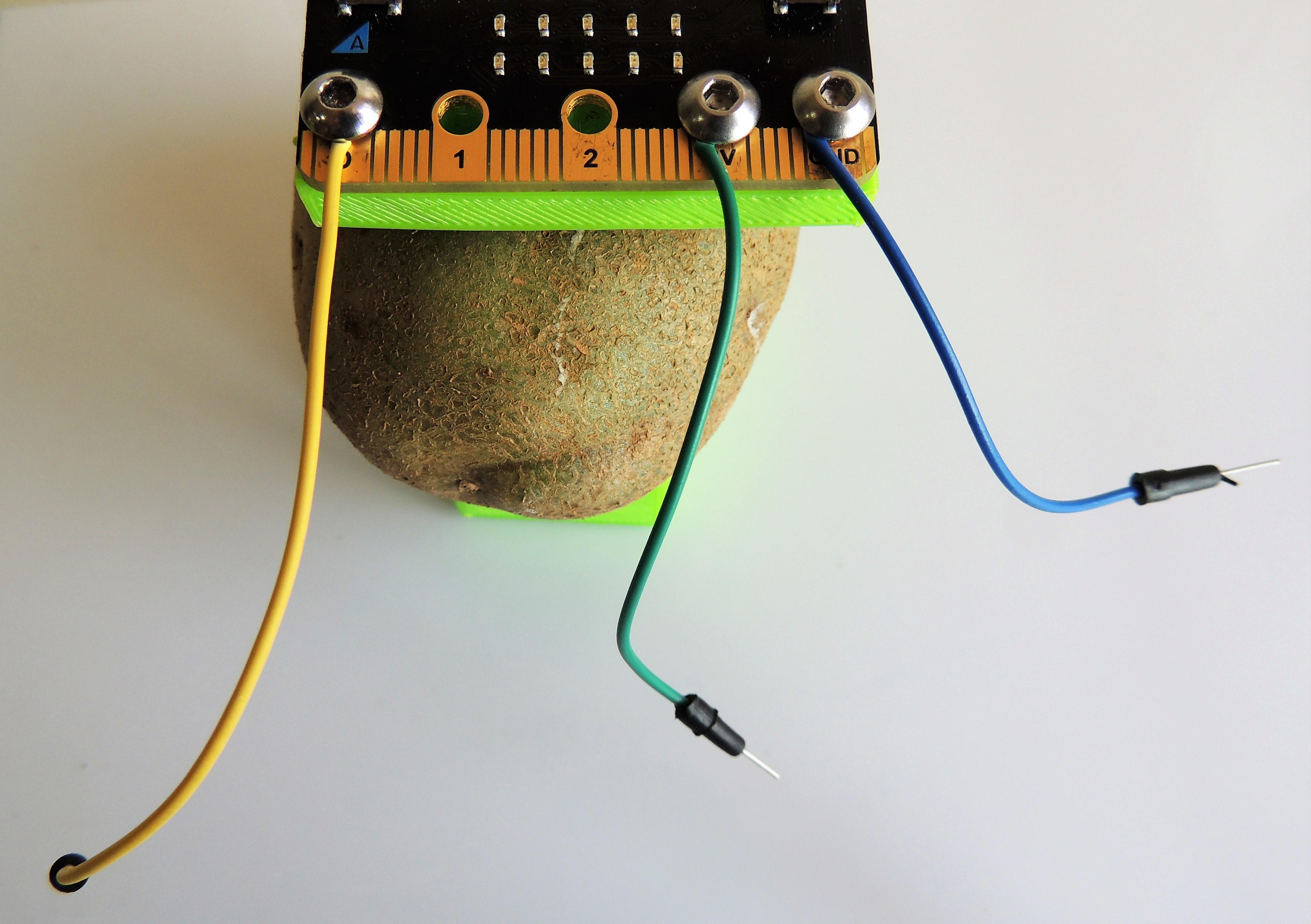
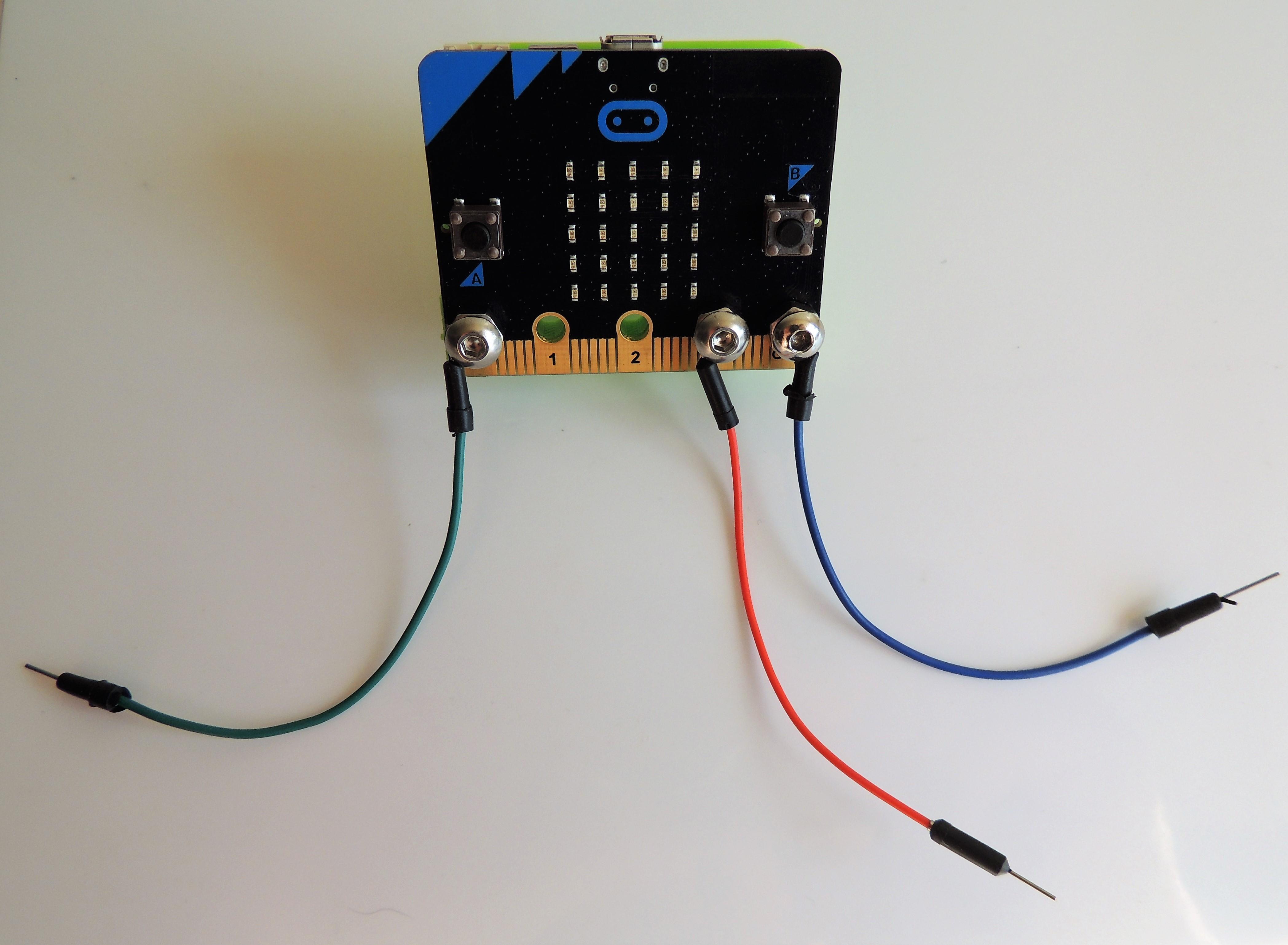
Bring the jumping wires and the bolts. Peel one of the ends from each jumping wire, exposing the metal core. Tie that end to a bolt. Use these bolts to attach the Micro:bit board to the 3D printed plate.
The bolts must be located in the pins 0, 3V and GND.
Servo Base
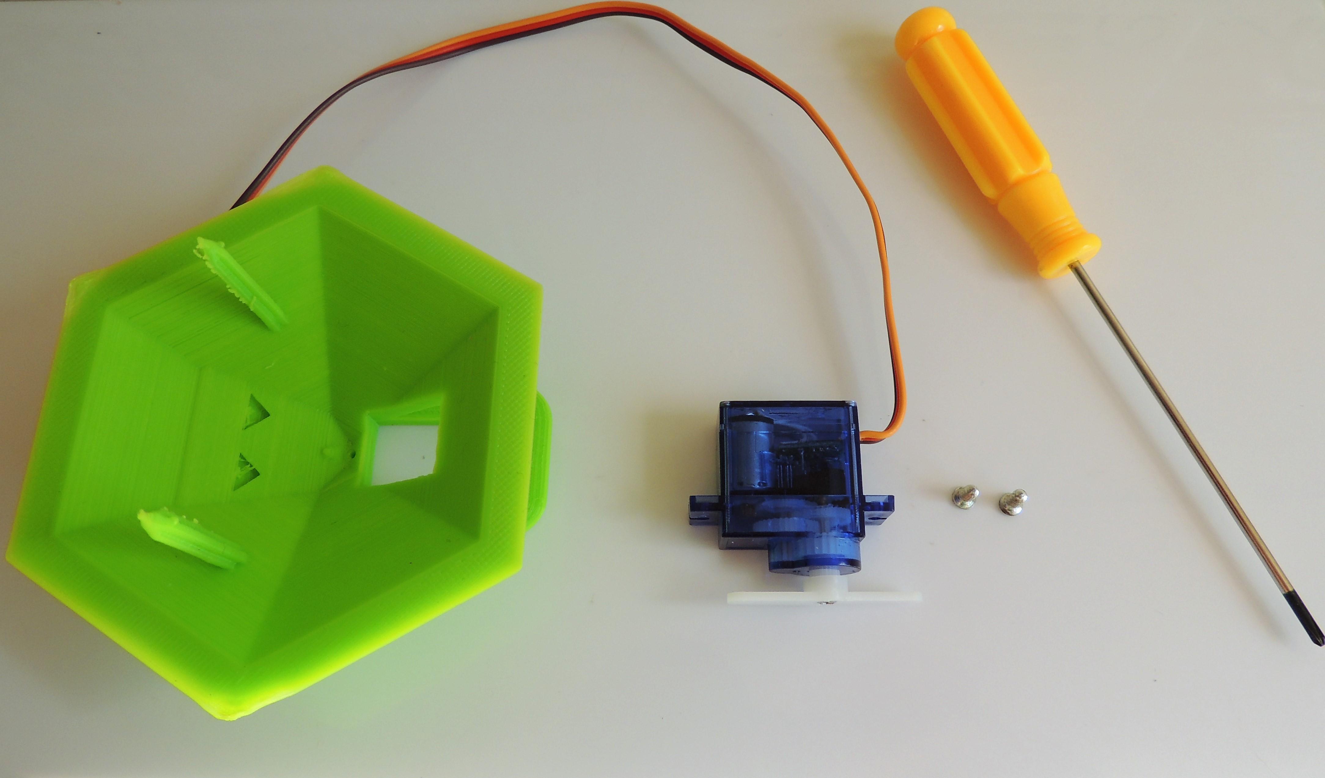
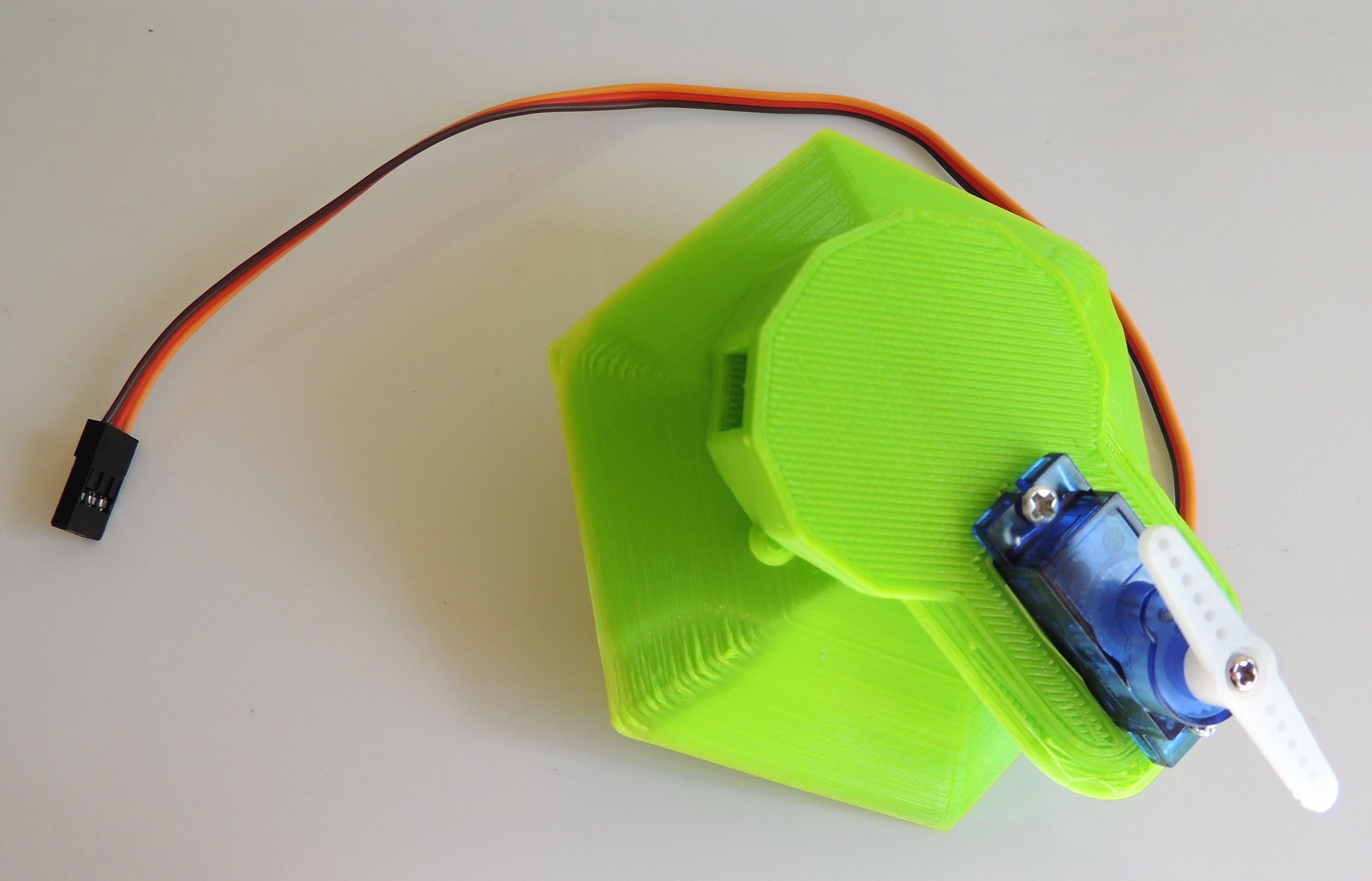
Insert the servo motor in its respective hole in the base, and fix it using the small screws and a screwdriver.
Attaching the Front Legs
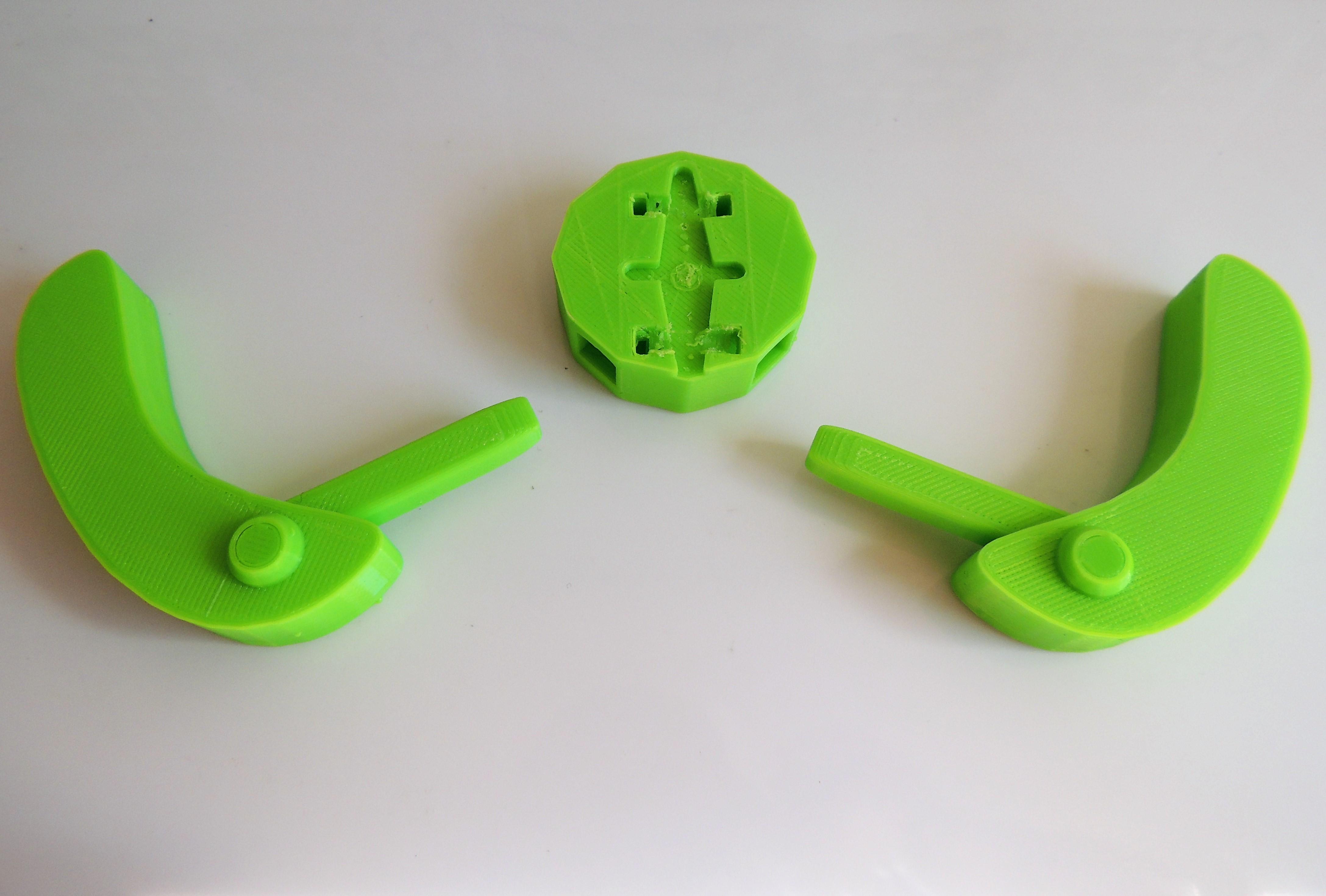
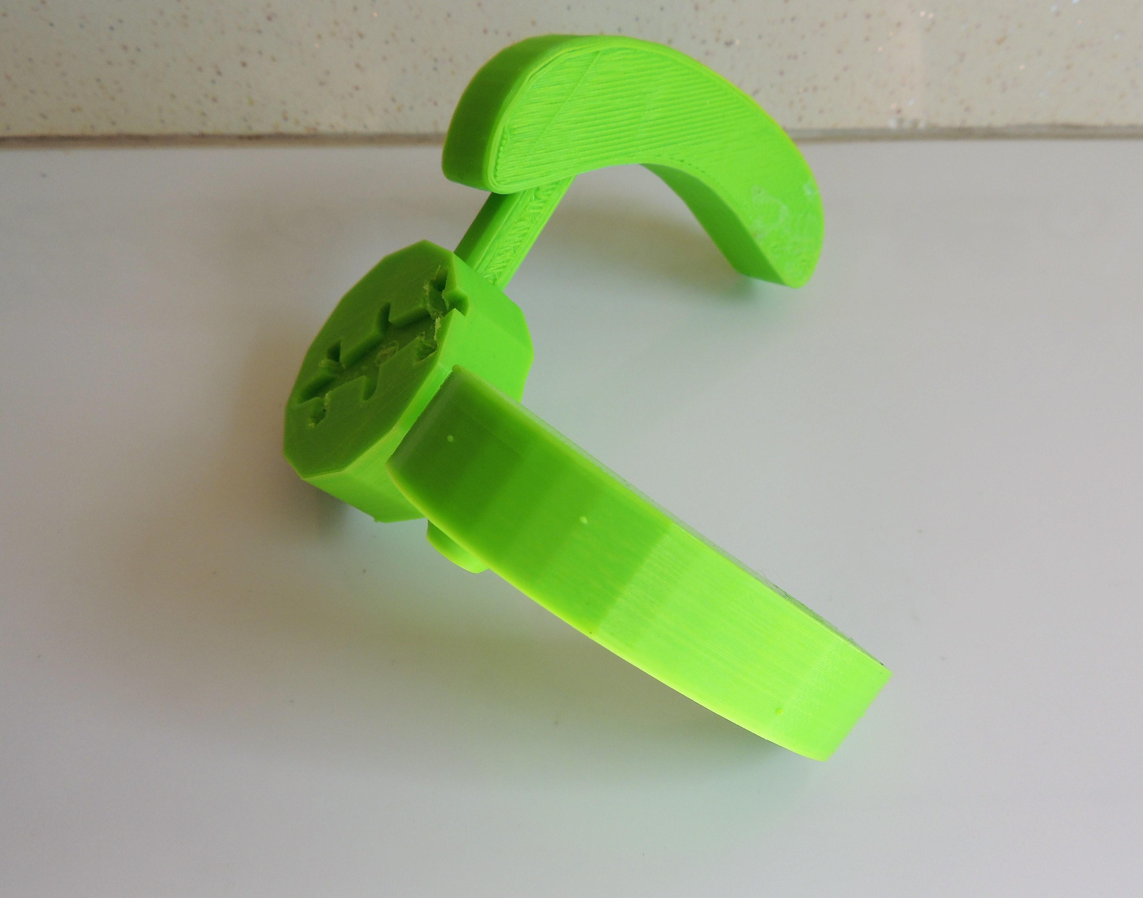
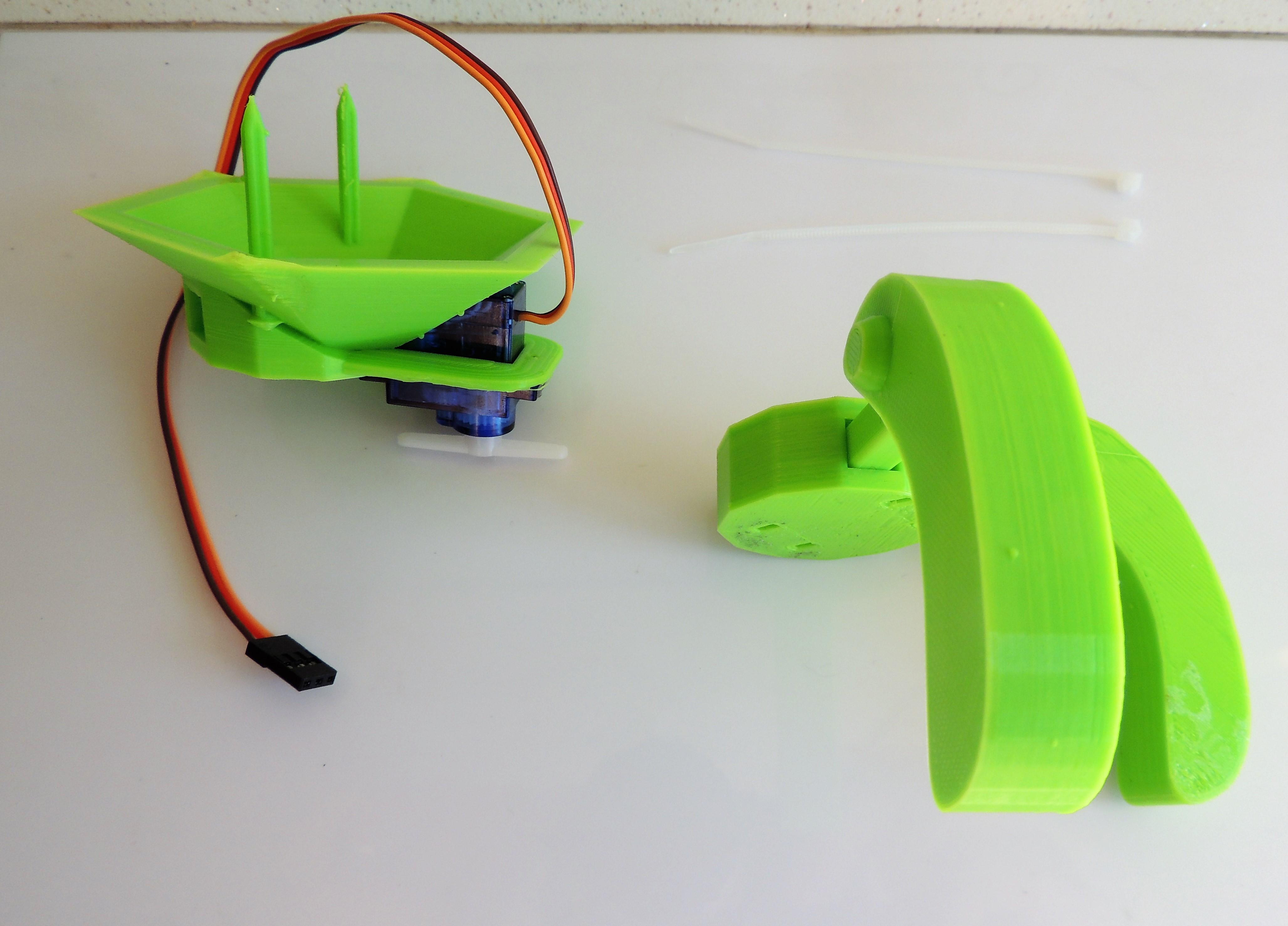
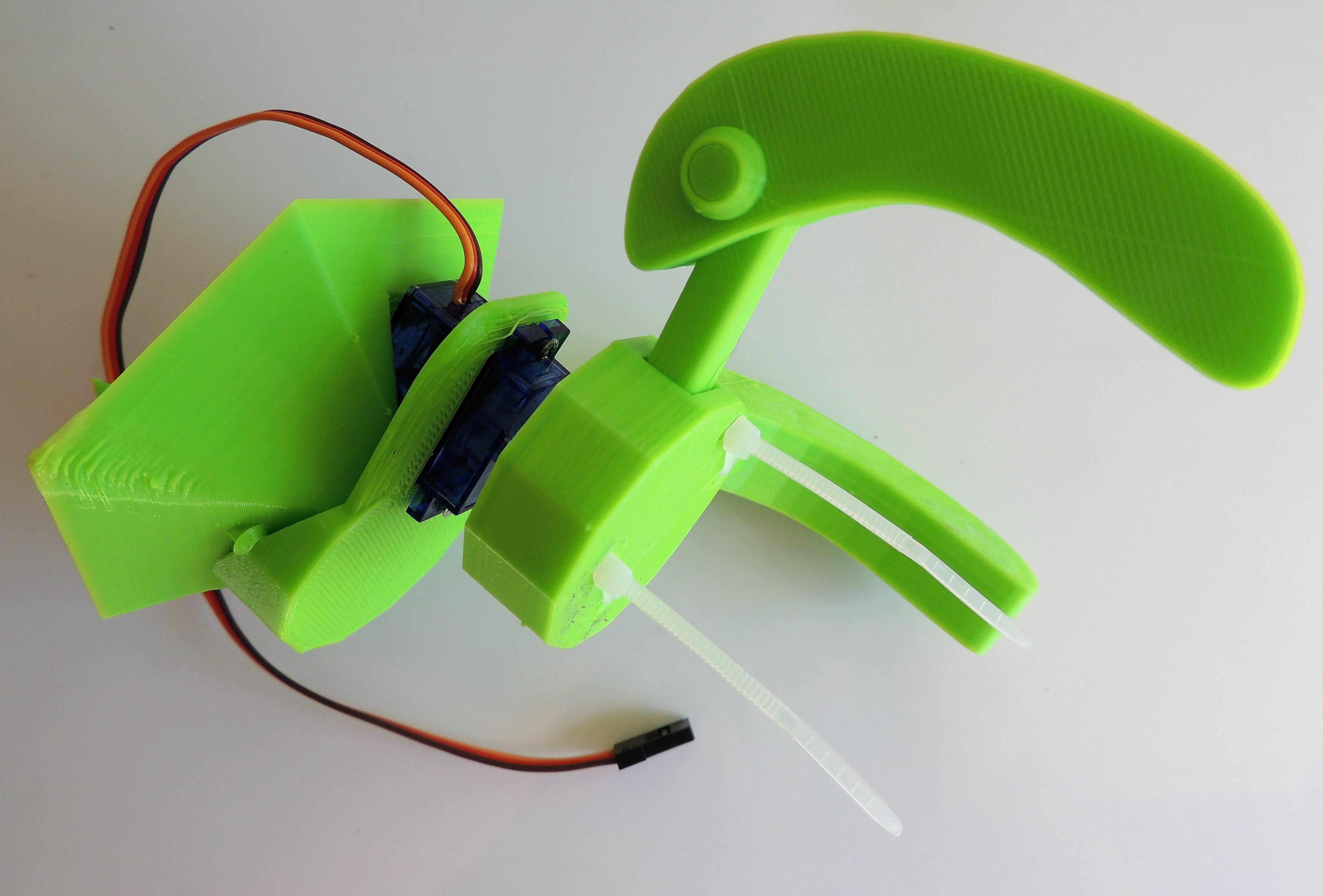
Insert the legs into the sockets of the cylinder prepared for the servo. Then, attach that ensemble to the servo arms. Use the zip ties to fix the cylinder to the servo arms.
Attaching the Back Legs
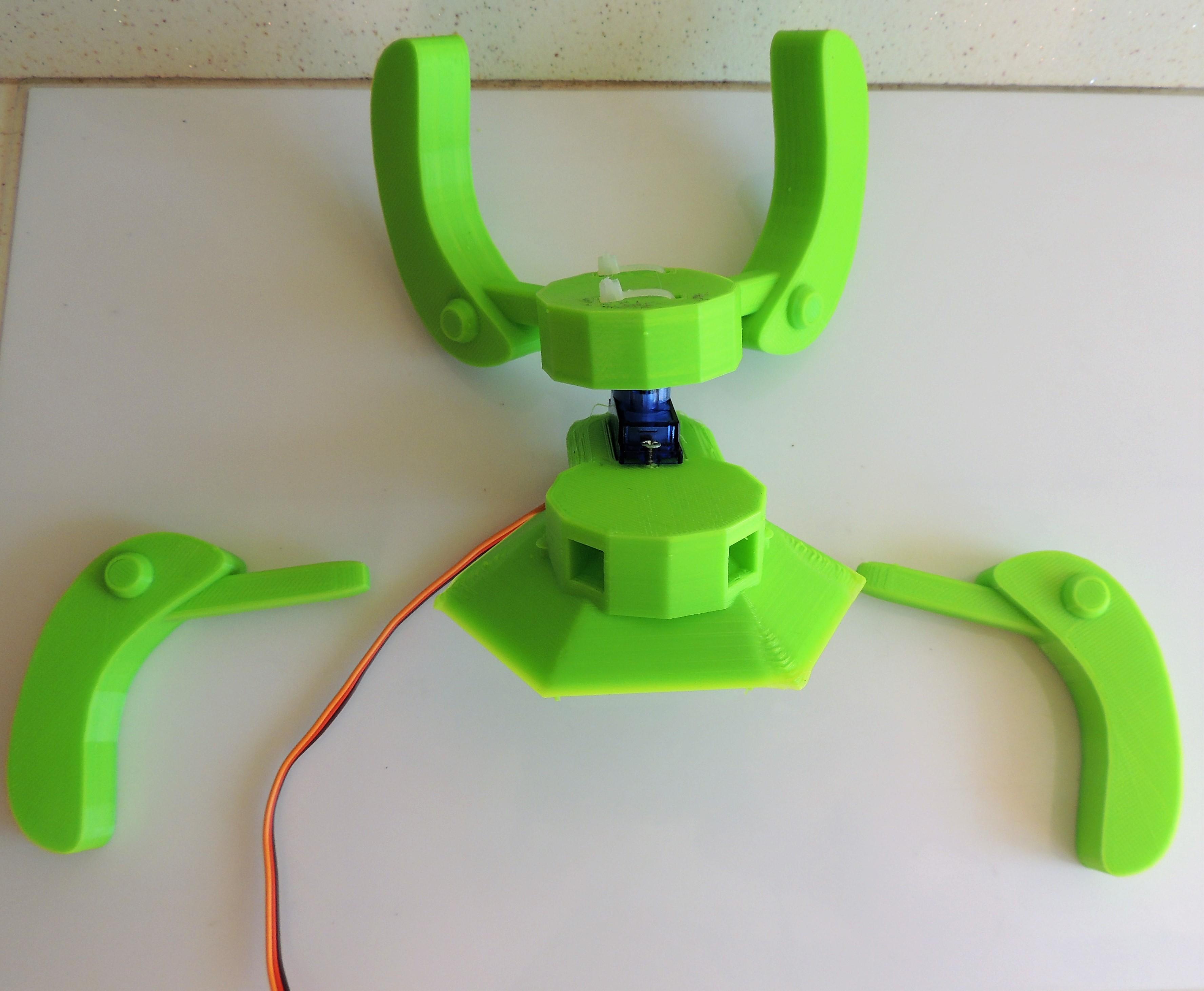
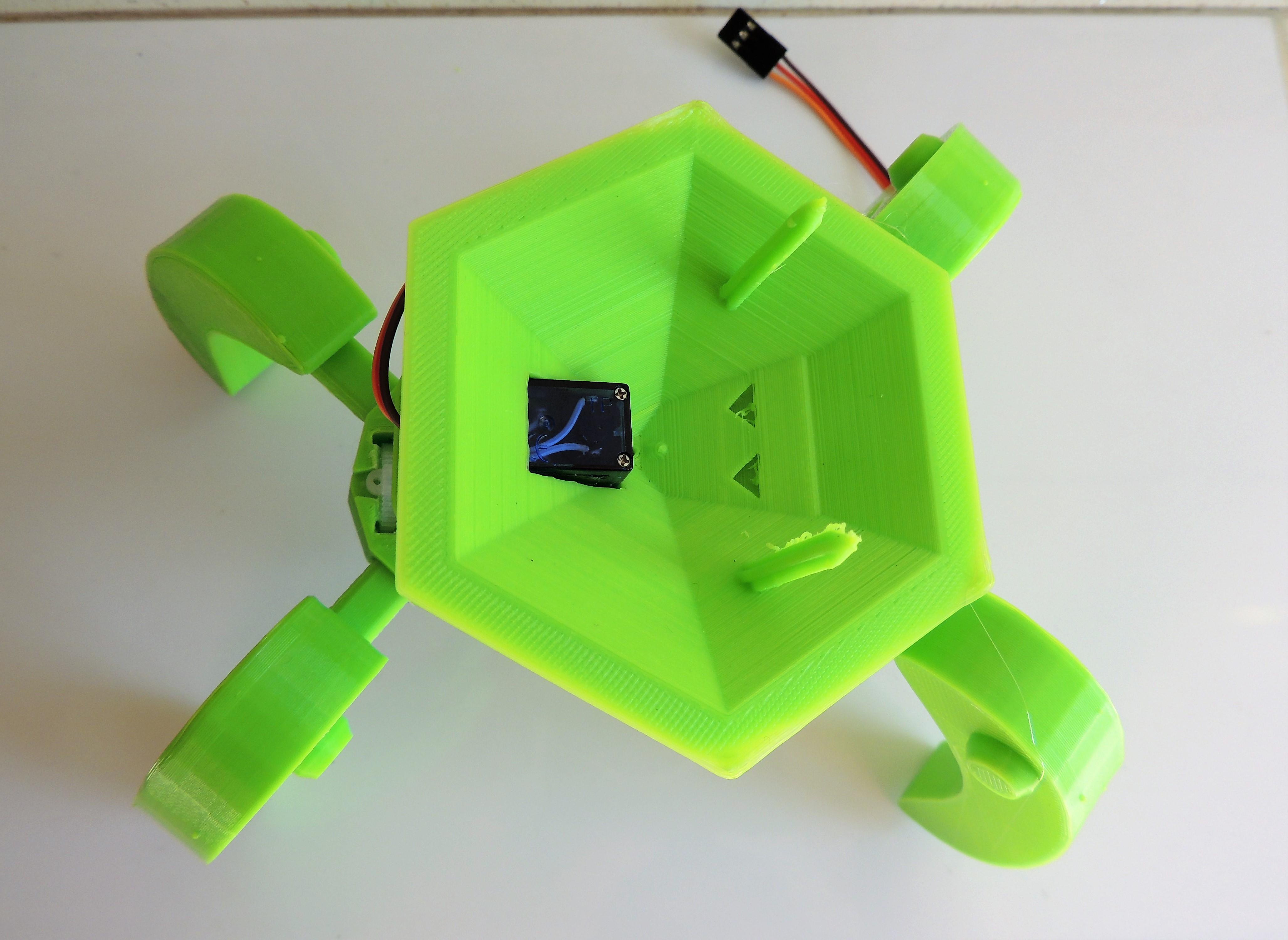
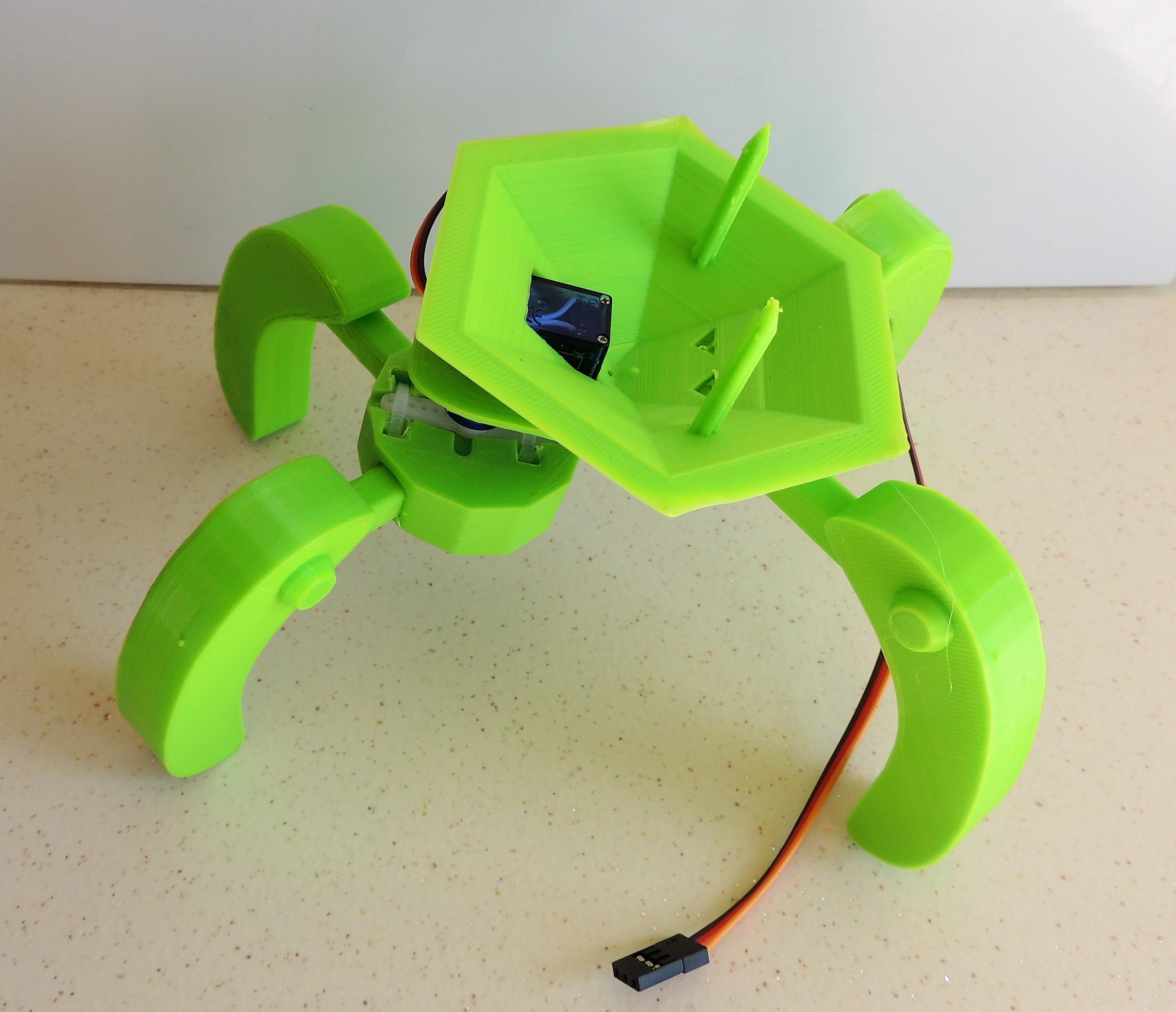
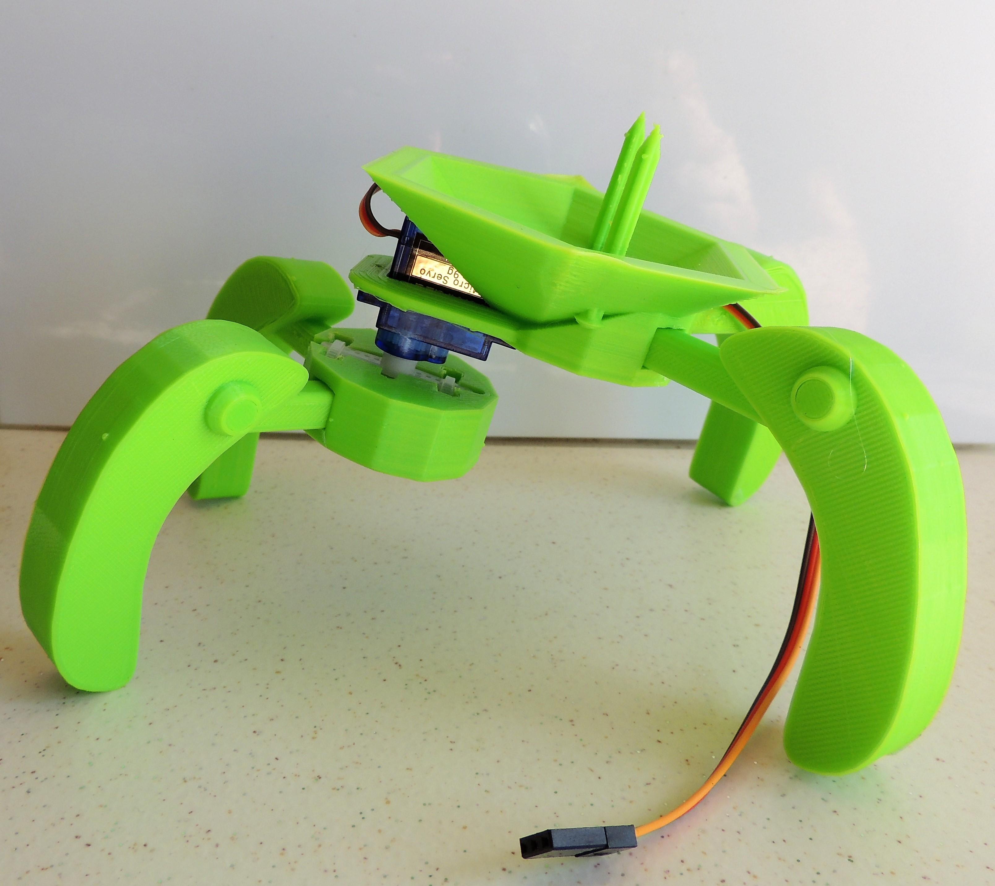
Take the remaining 2 legs and attach them in the back sockets. Check that the complete mechanical ensemble looks like the photo.
Assembling the Battery Backpack
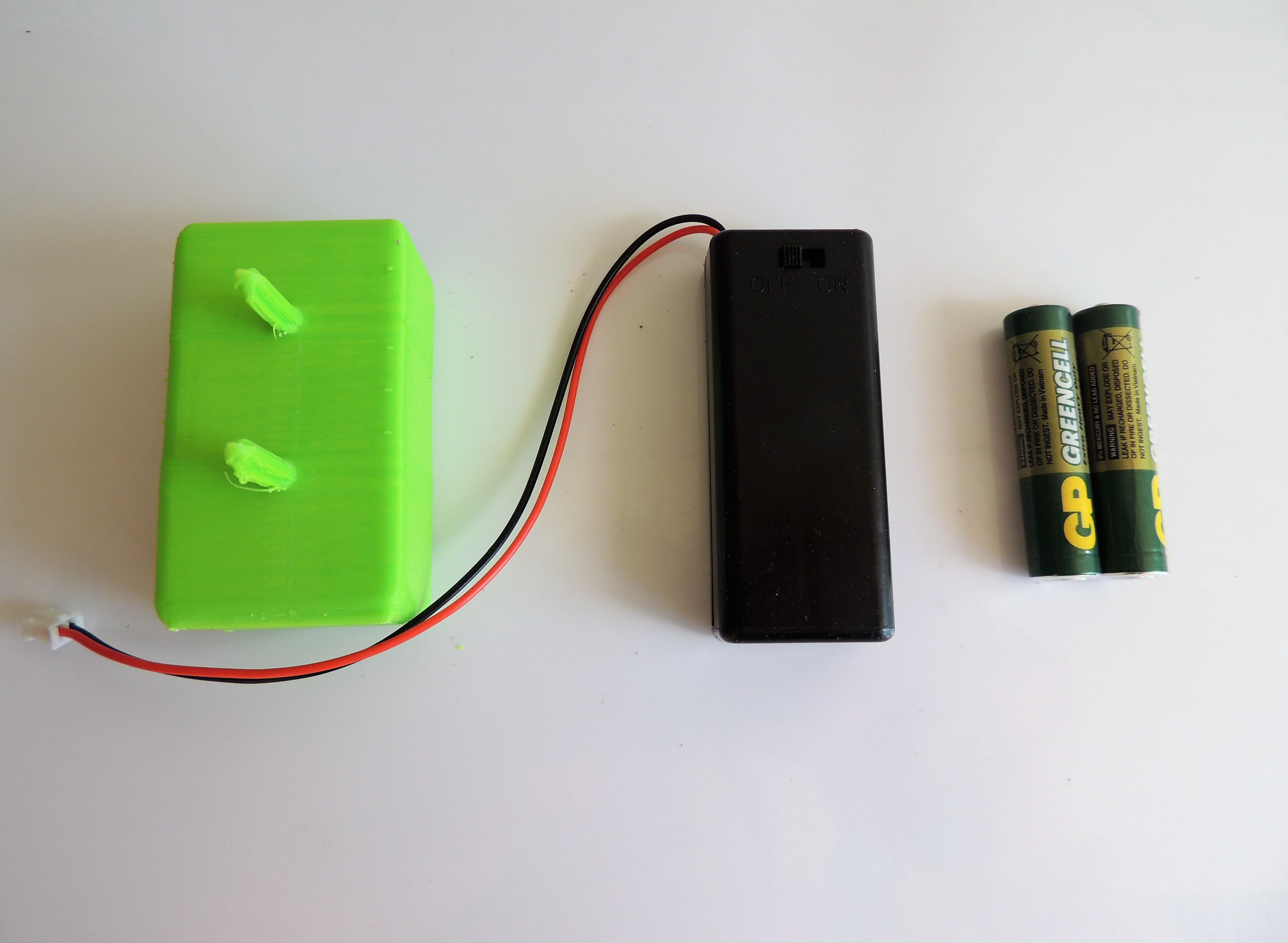
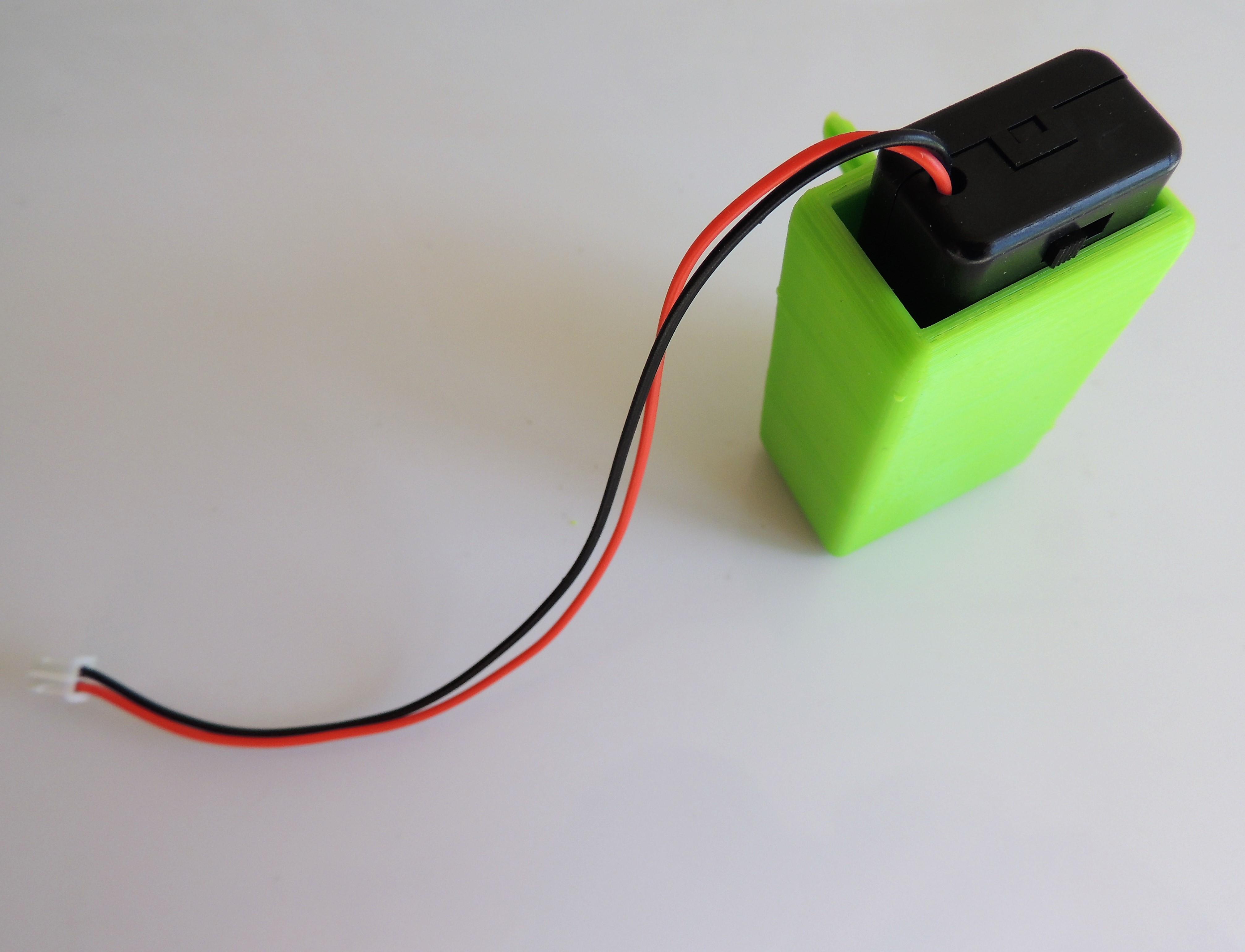
Insert 2 AAA batteries in the battery holder, and place it in the battery backpack.
Attaching the Components to the Potato
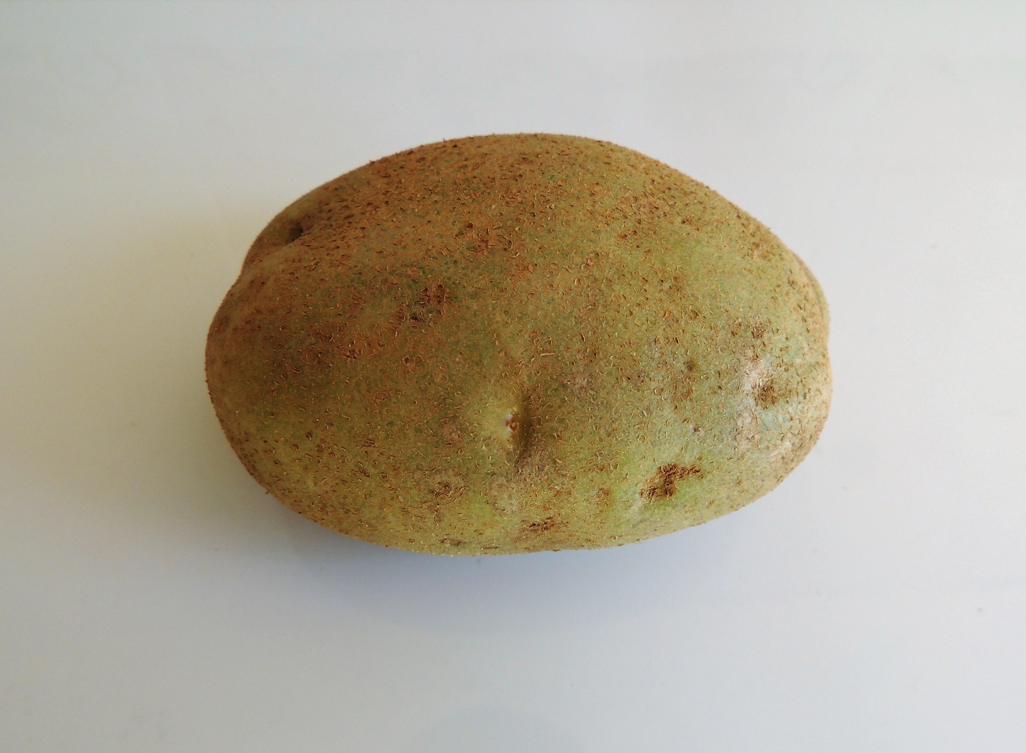
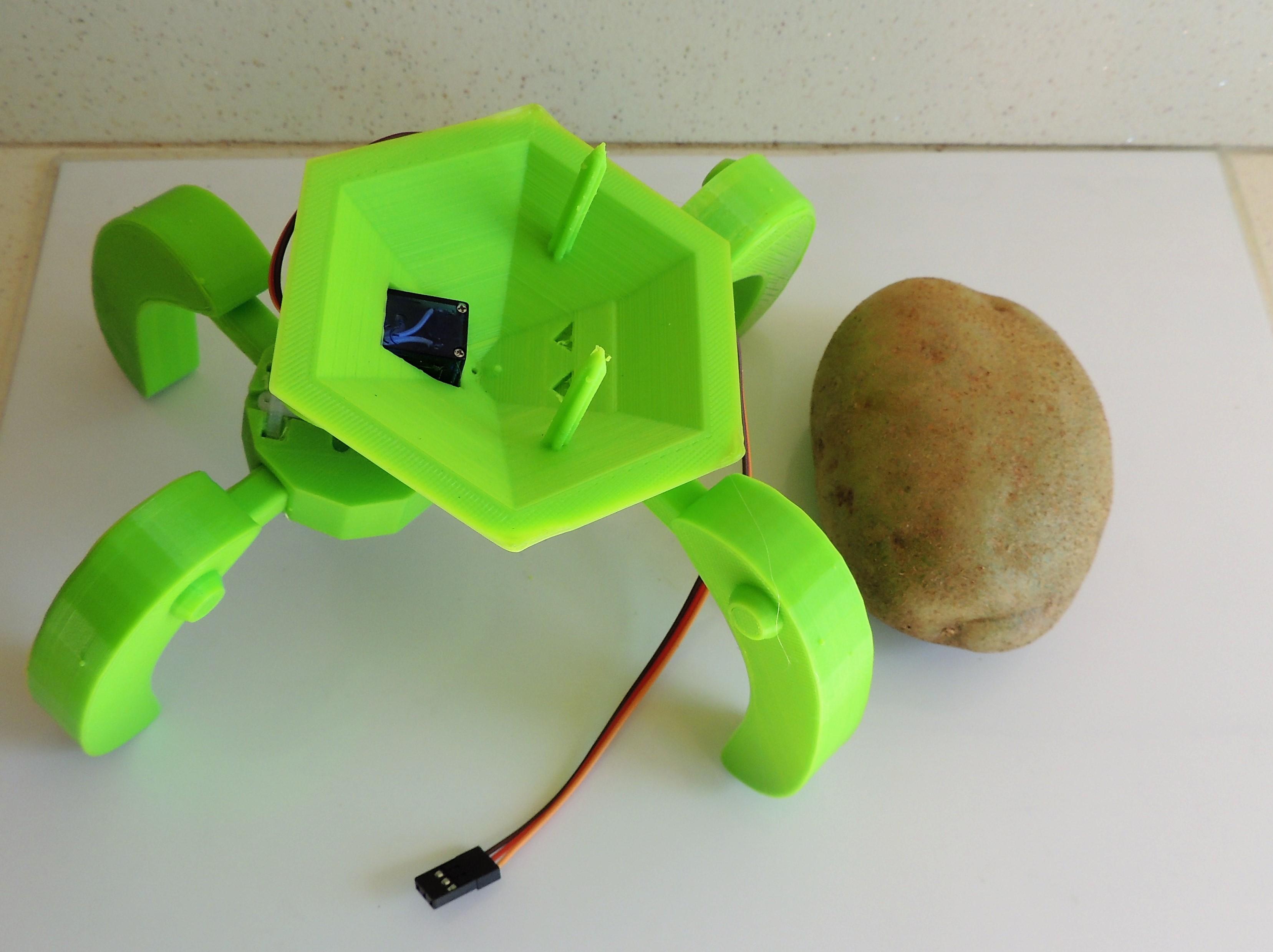
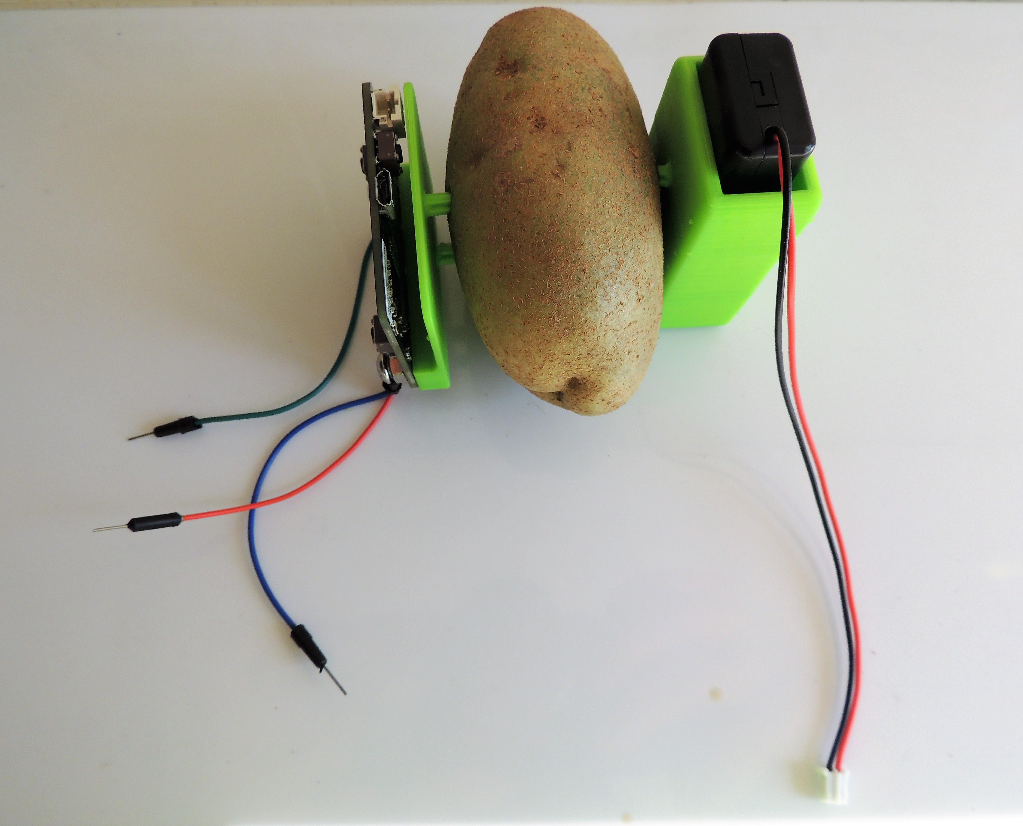
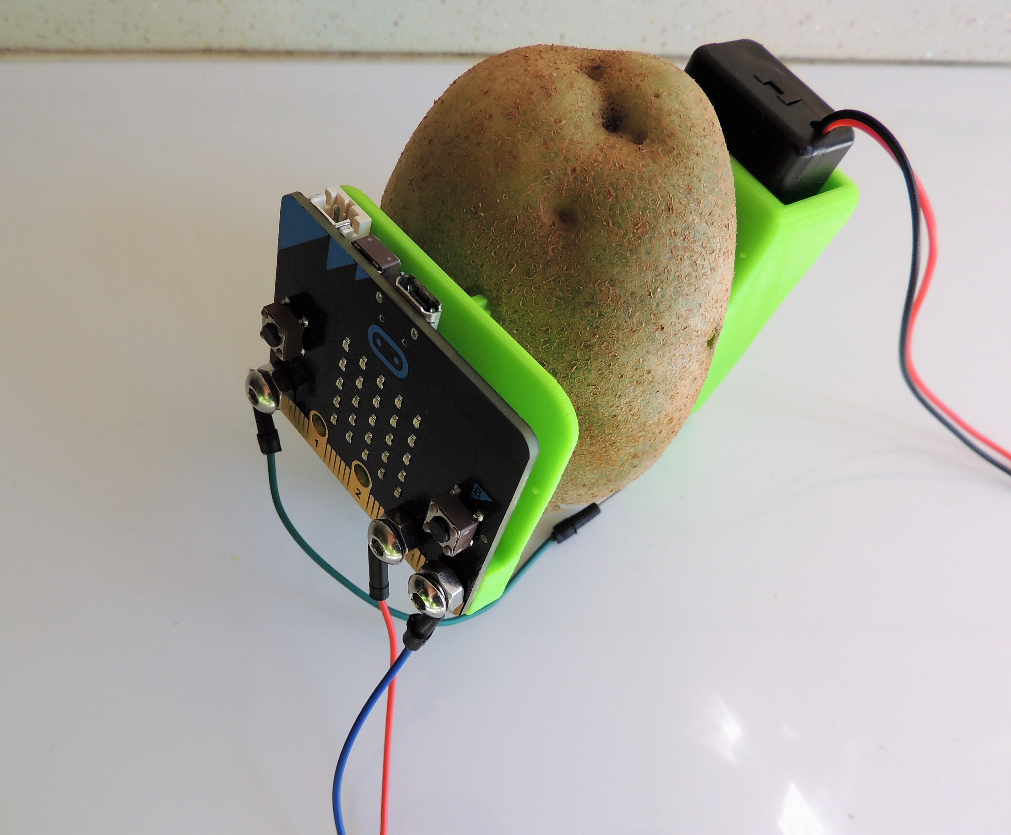
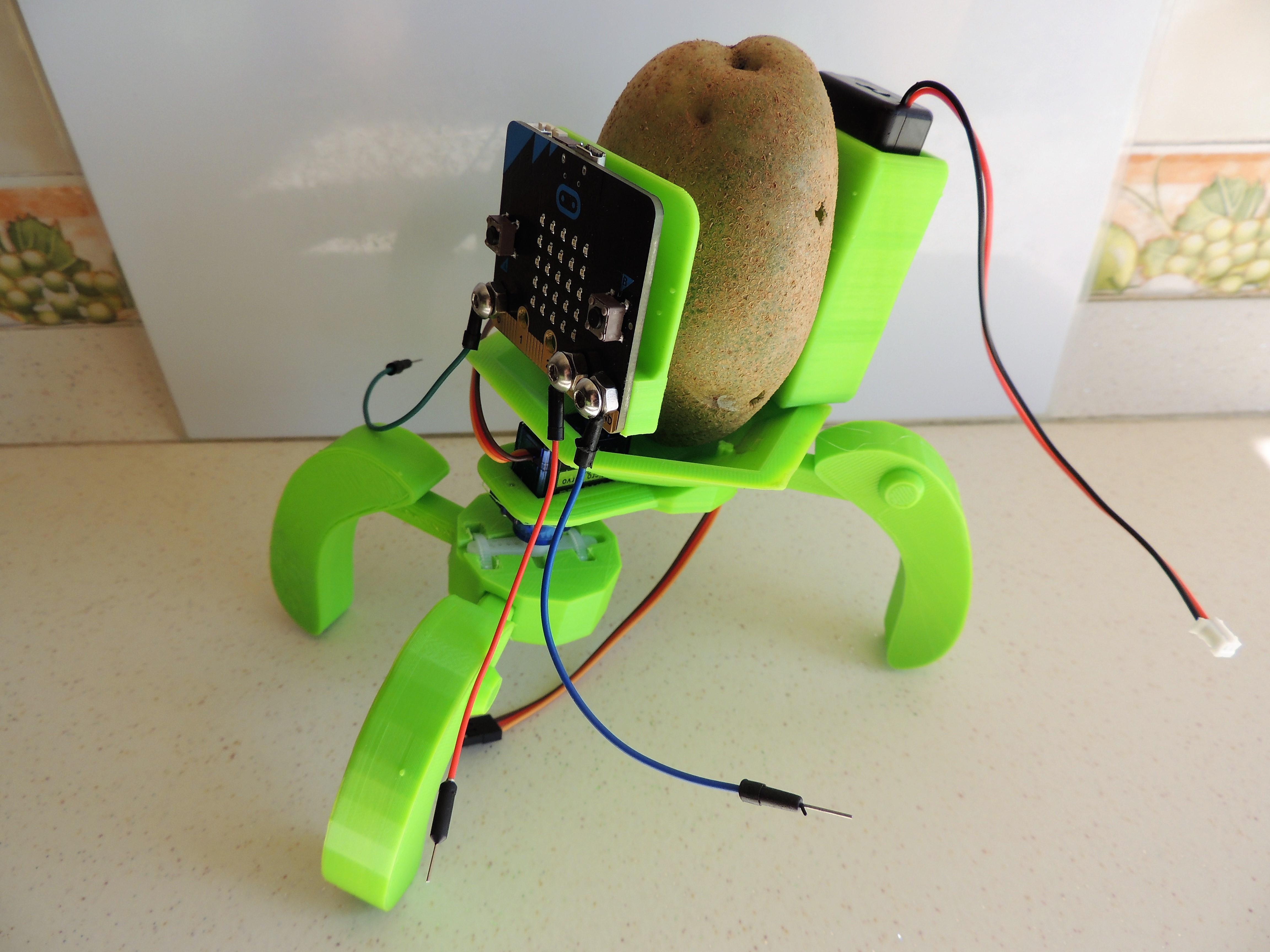
Take the potato. Insert the Micro:bit plate in one of the largest areas, and insert the battery backpack on the opposite side. Then, insert the spikes of the base on the bottom of the potato. Be careful! If not, you may get hurt or break the spikes. Or both.
Connecting the Cables And... Ready to Go!
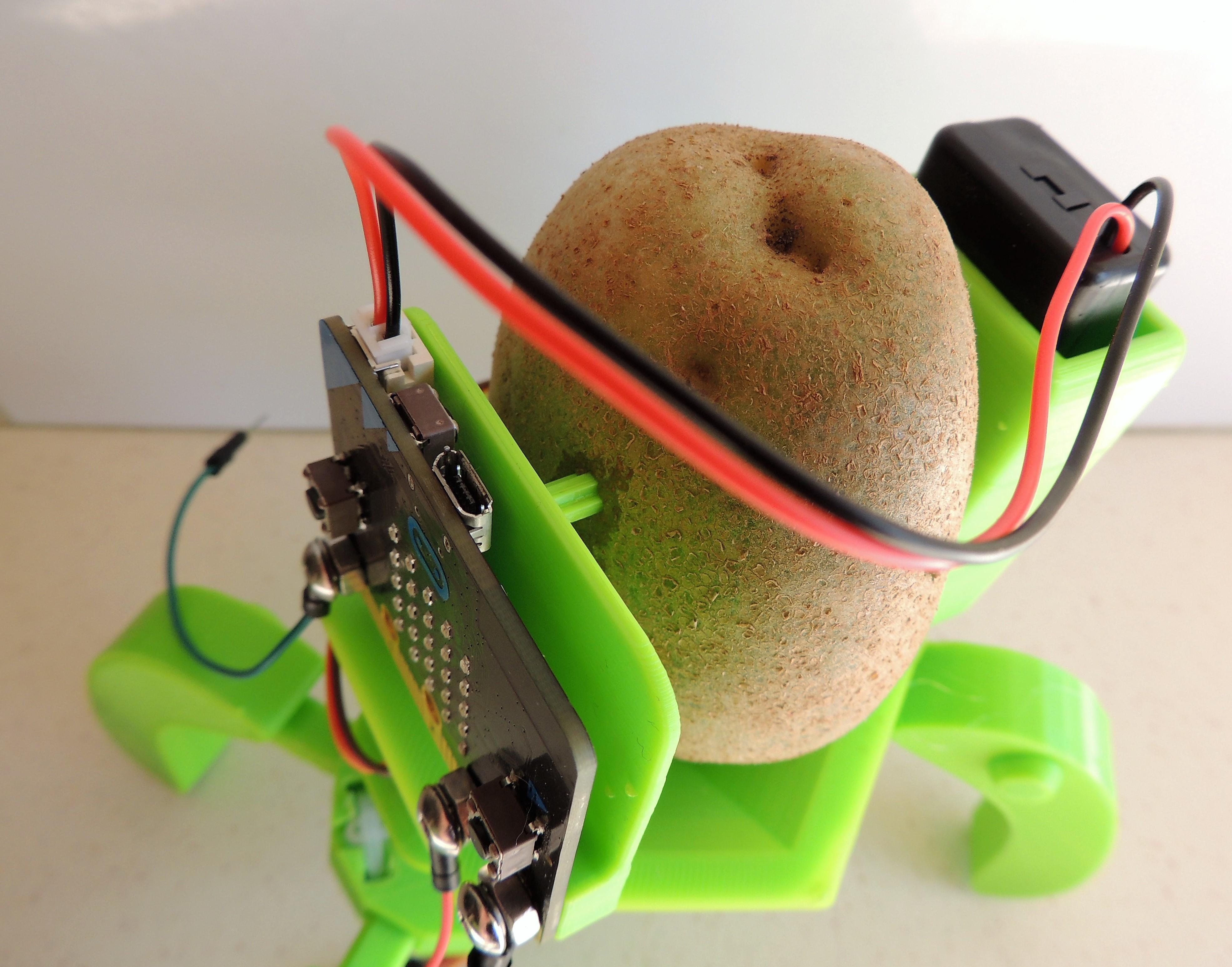
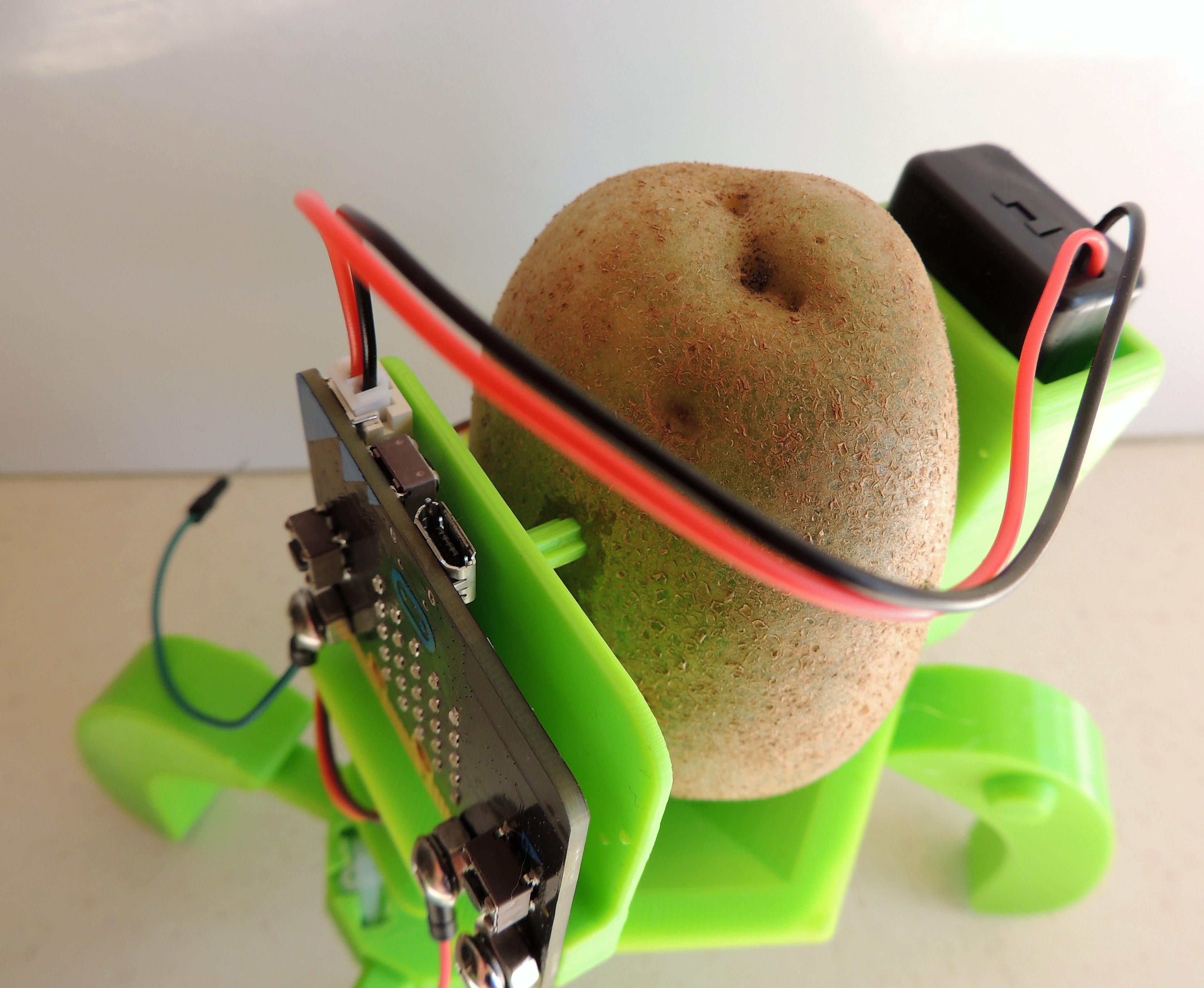
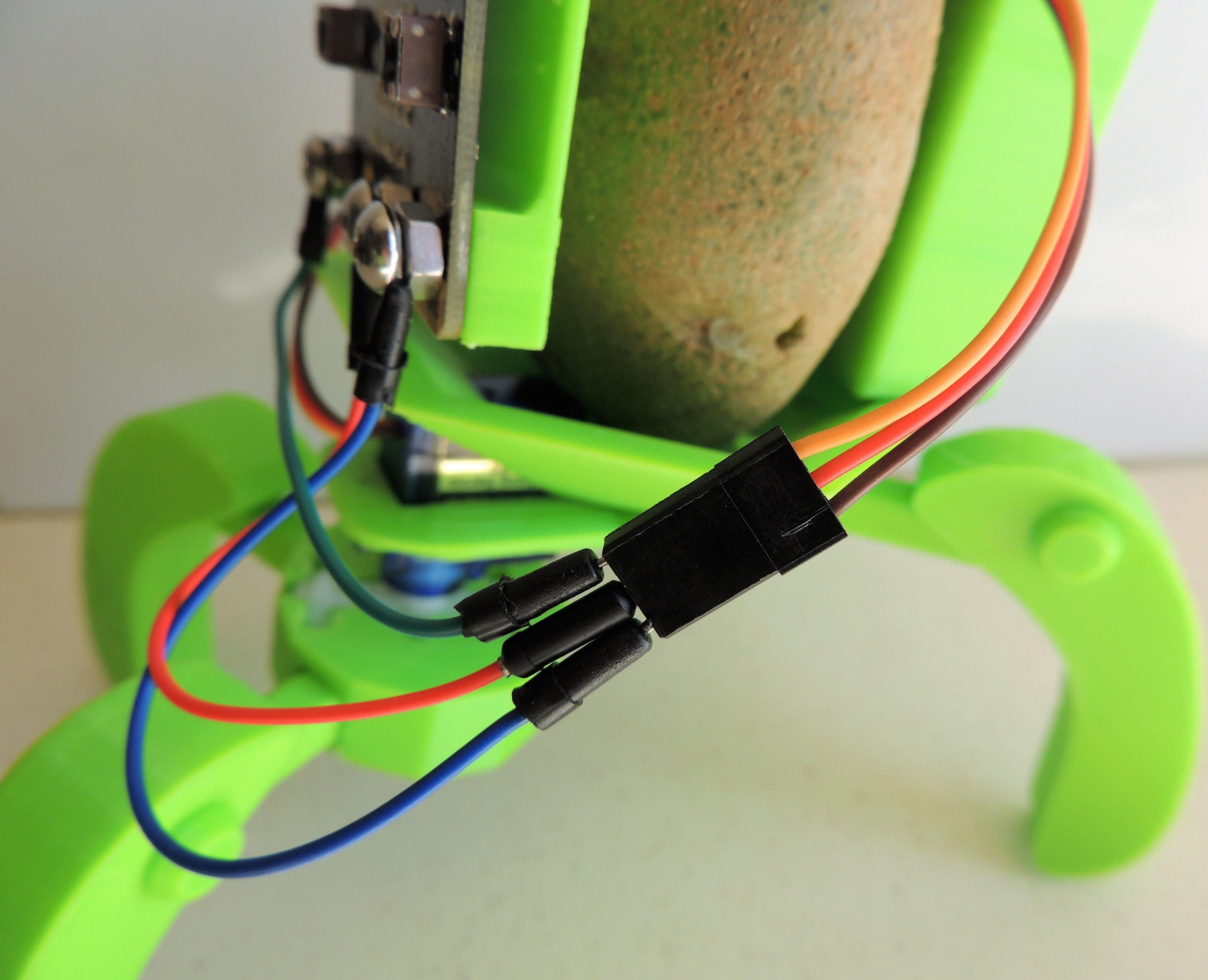
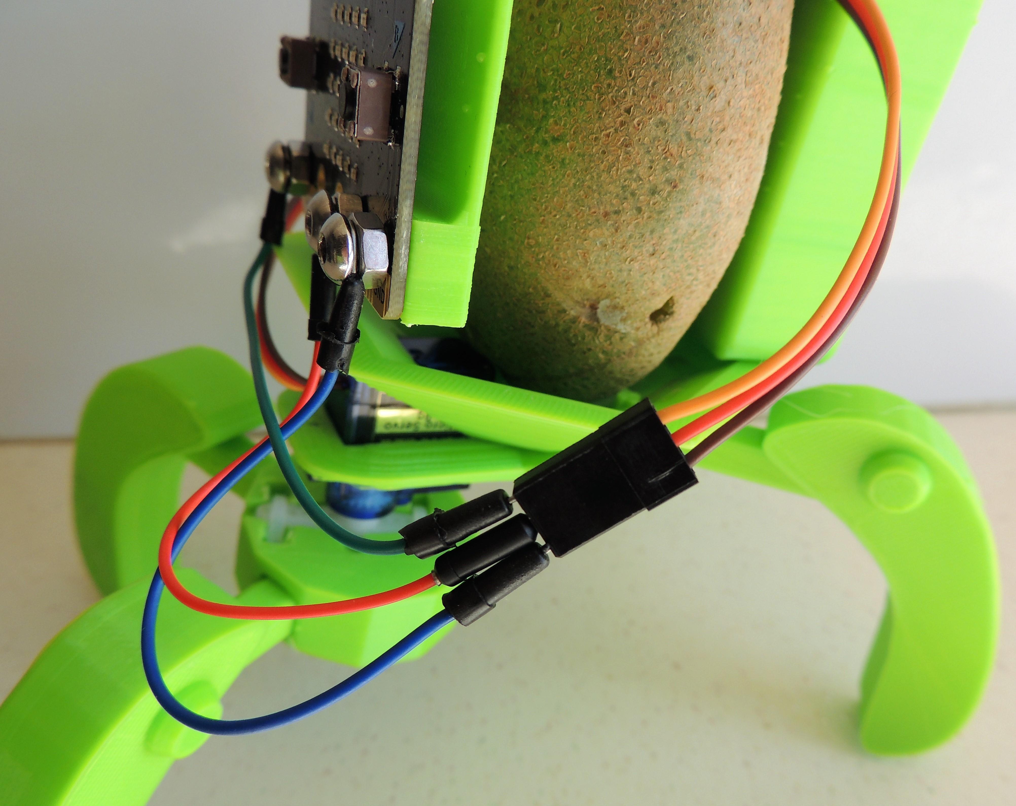
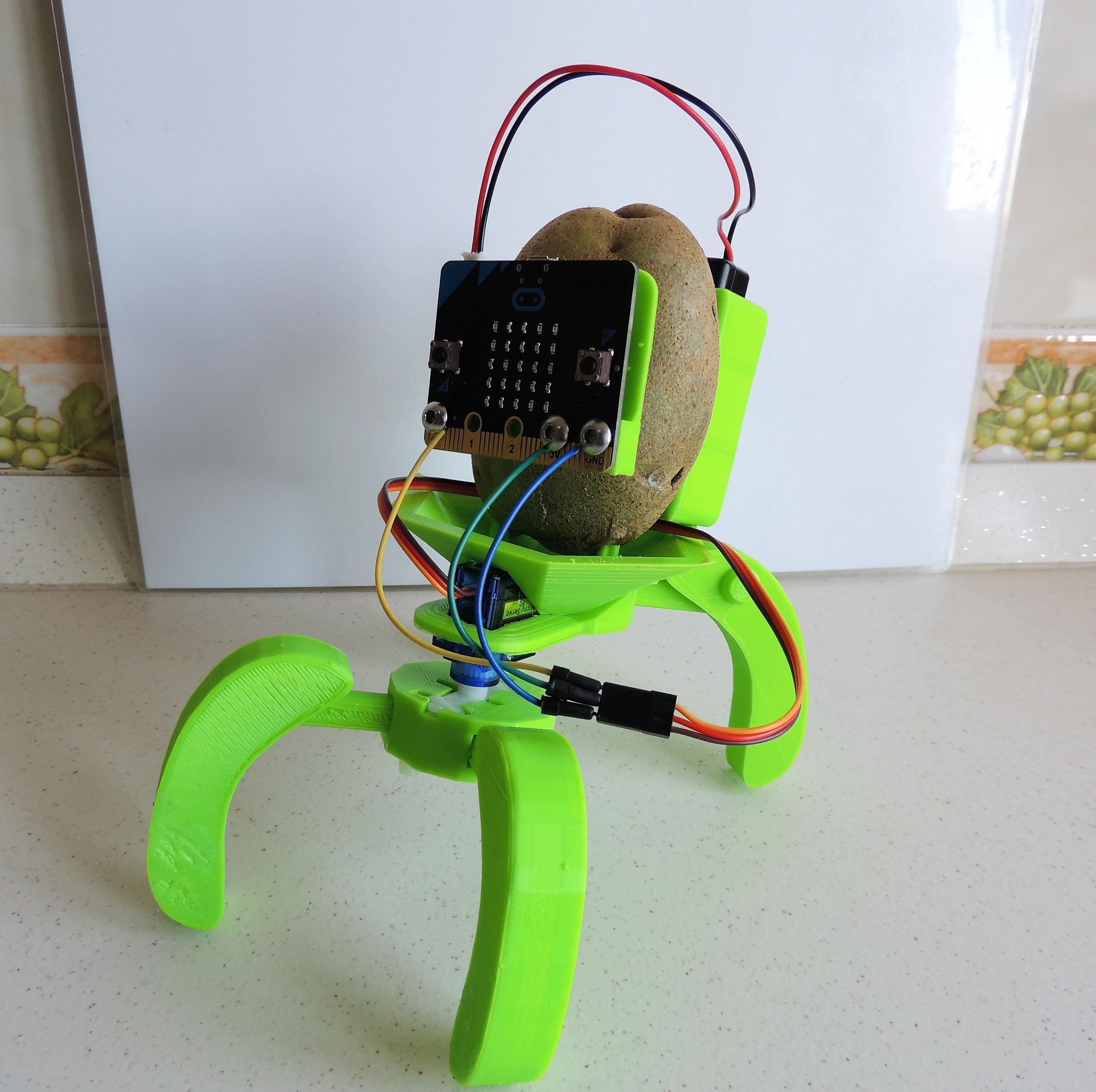
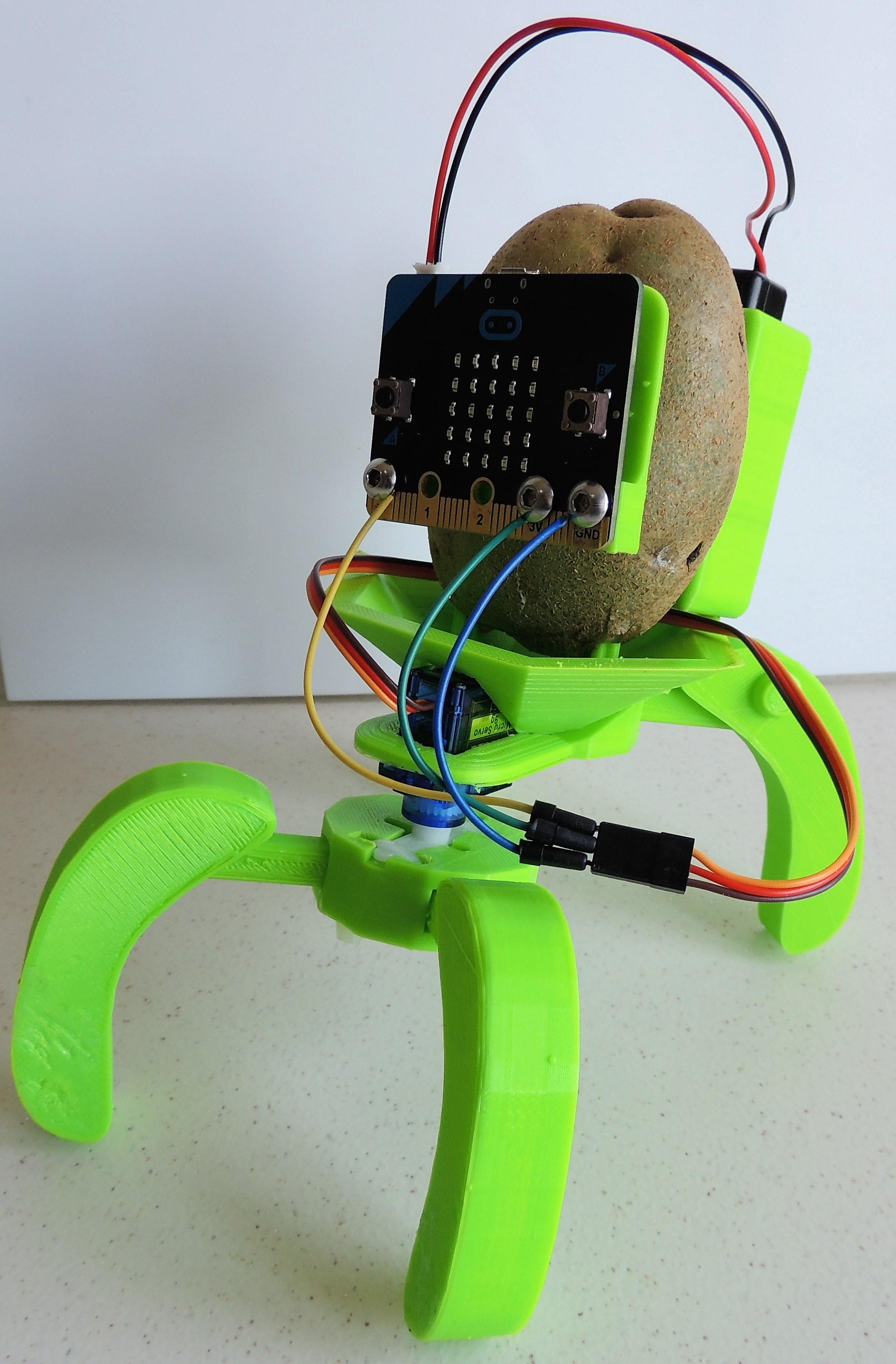
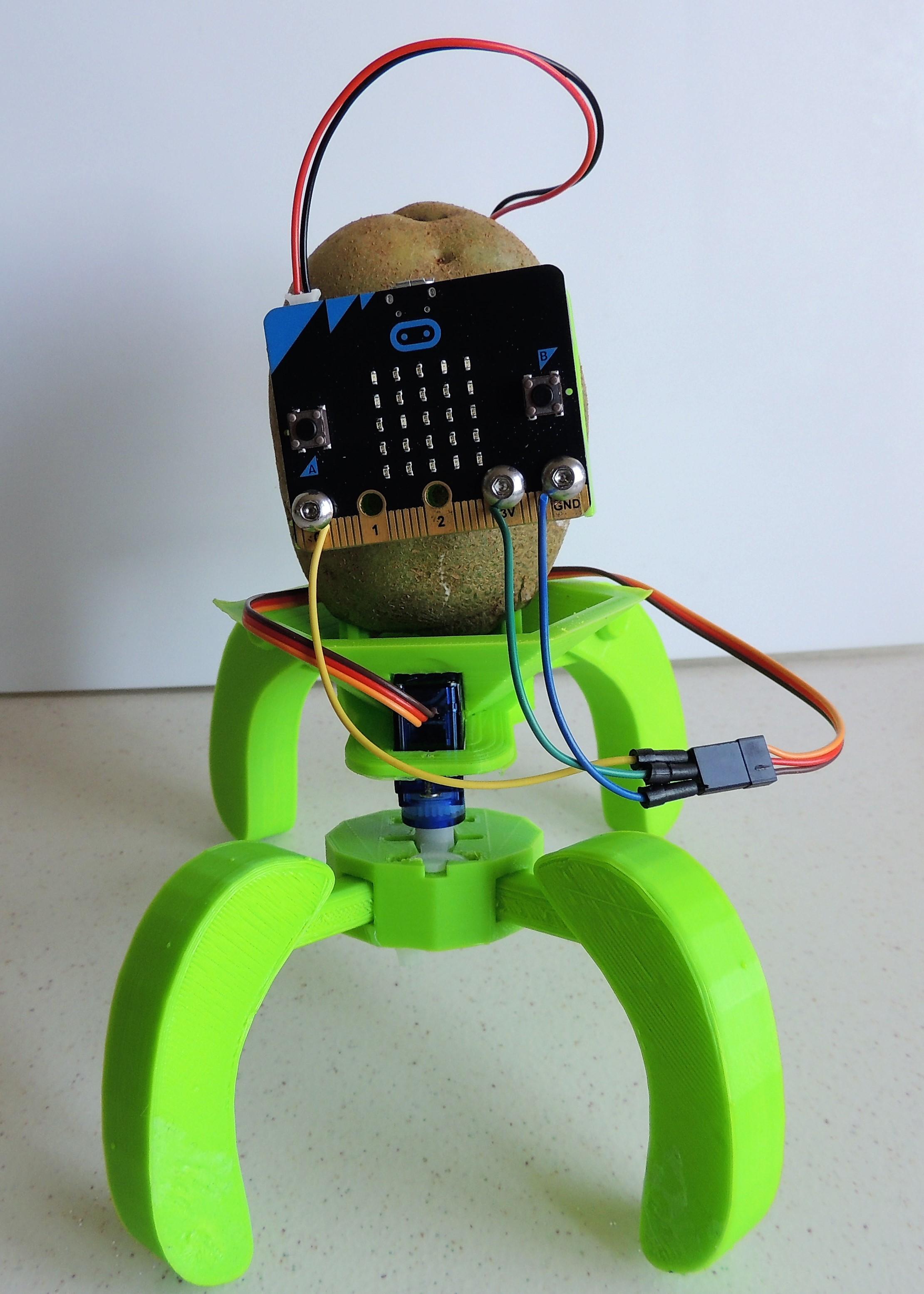
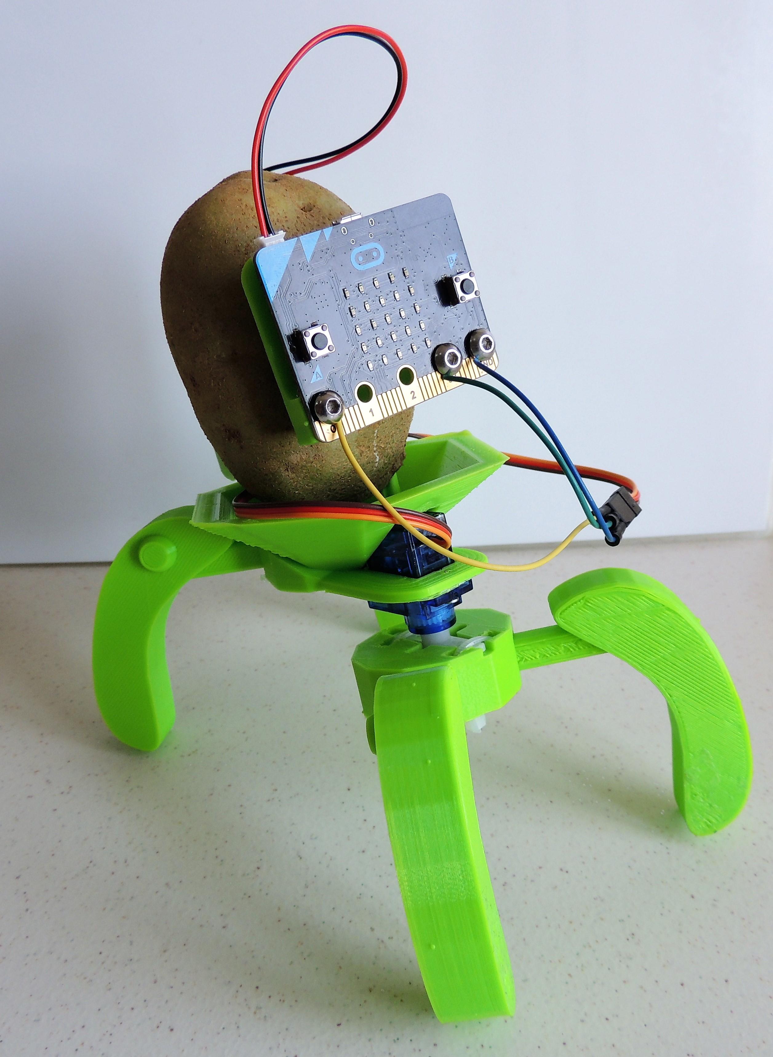
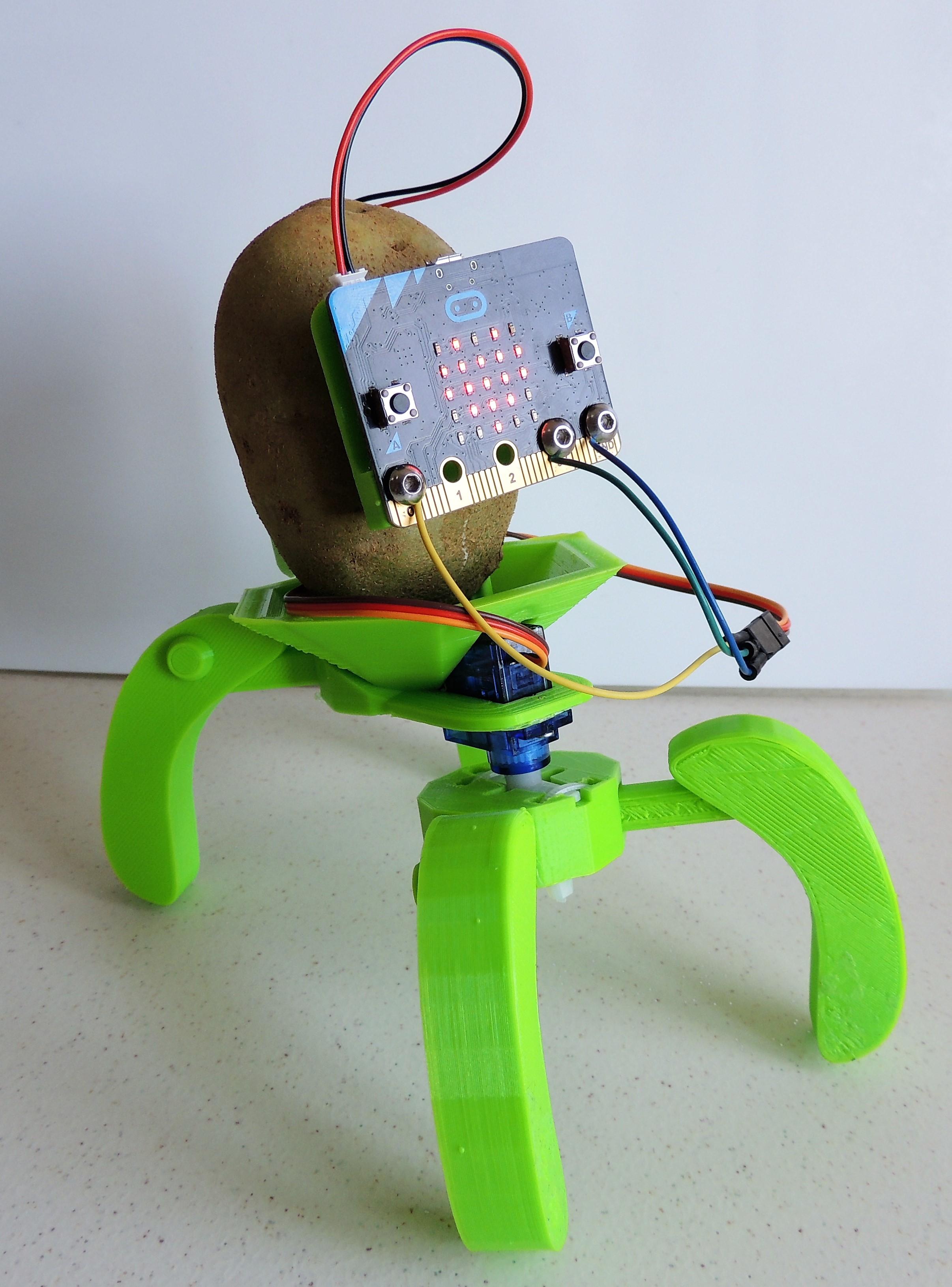
Connect the servo cables to the Micro:bit pins this way:
P0: orange servo wire
3V: red servo wire
GND: brown servo wire
Connect the battery holder to the Micro:bit. If you haven't downloaded the code yet, do it now. Turn the switch on and let's take our potato for a walk!