Tinkercad - Go Pro Mount
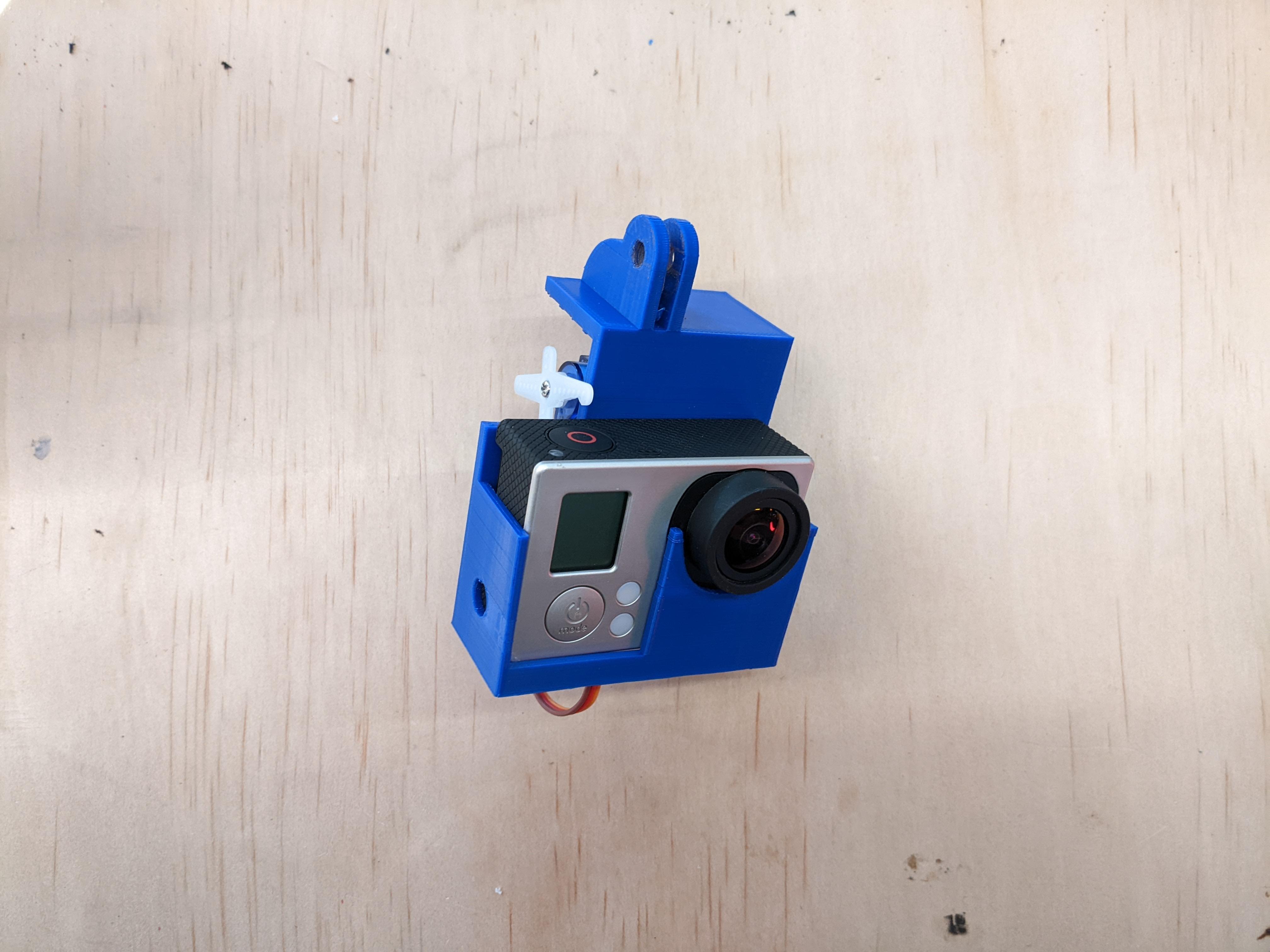
I'm a Teacher at a small independent school. Our School has an old GoPro Hero 3 and I wanted to be able to control it remotely (with a control board).
Truth is, we have a drone (a pixhawk 2.4.8) at school and it has the capacity to control external servos, and mounting the camera under the drone to take photos when it got to specific GPS coordinates seemed cool and useful.
This project led to the creation of a unit we do in our Australian Curriculum - Digital Technologies class where students build real world solutions that can be mounted under a drone. Works out to be about $500 worth of drone and the prototype materials are relatively cheap. So this is a very low cost way of using drones in class.
This project is used as an example for the students as an introduction into the design, engineering and prototyping techniques.
For those interested, it goes hand in hand with this assignment (still a work in progress)
Supplies
Essential:
Laptop
Mouse
Optional:
3D printer
Small servo
2 screws
*Controller board (microbit, Arduino, pixhawk)
*Not covered in this instructable
Prototype 1 - Summary
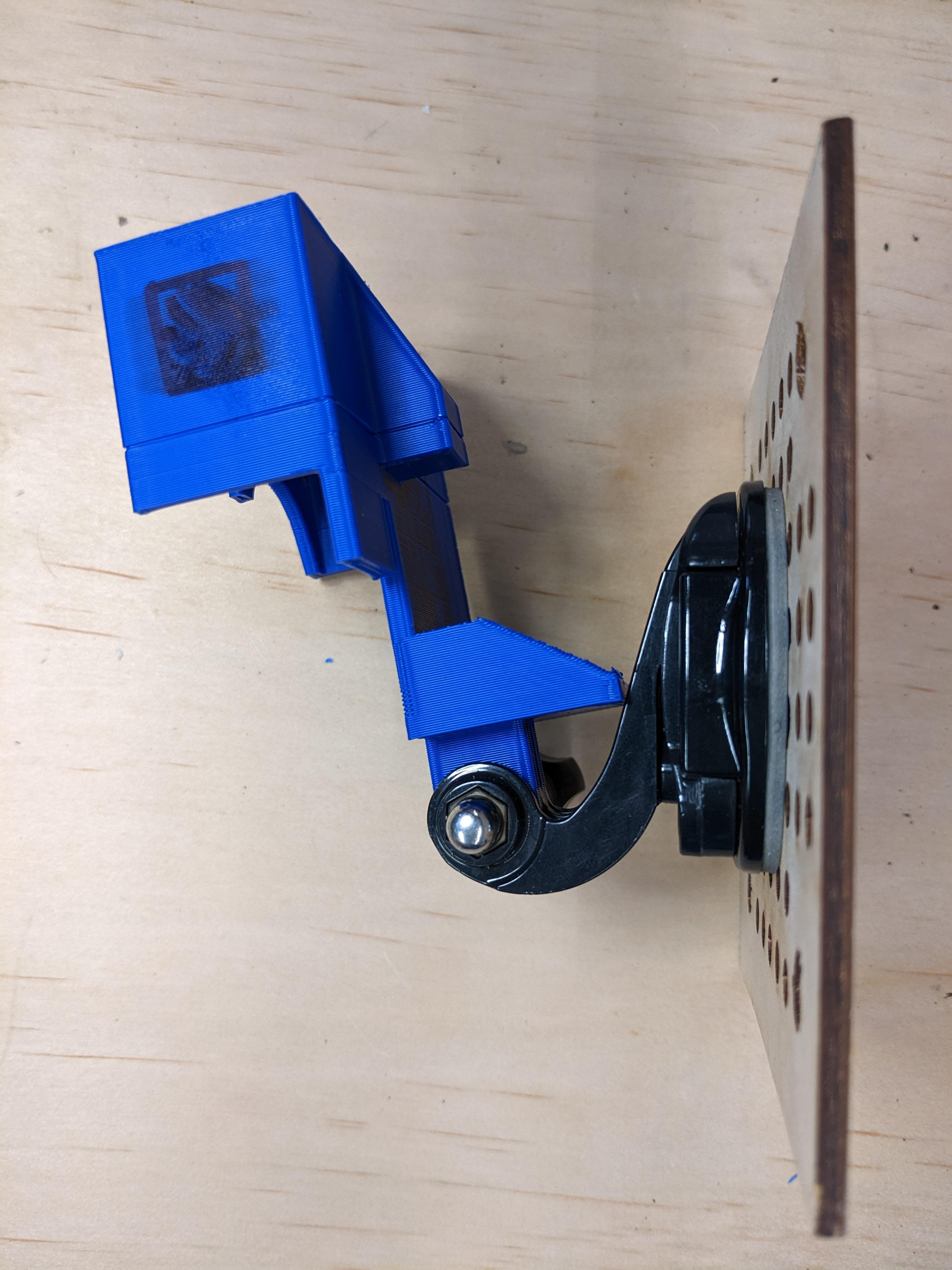
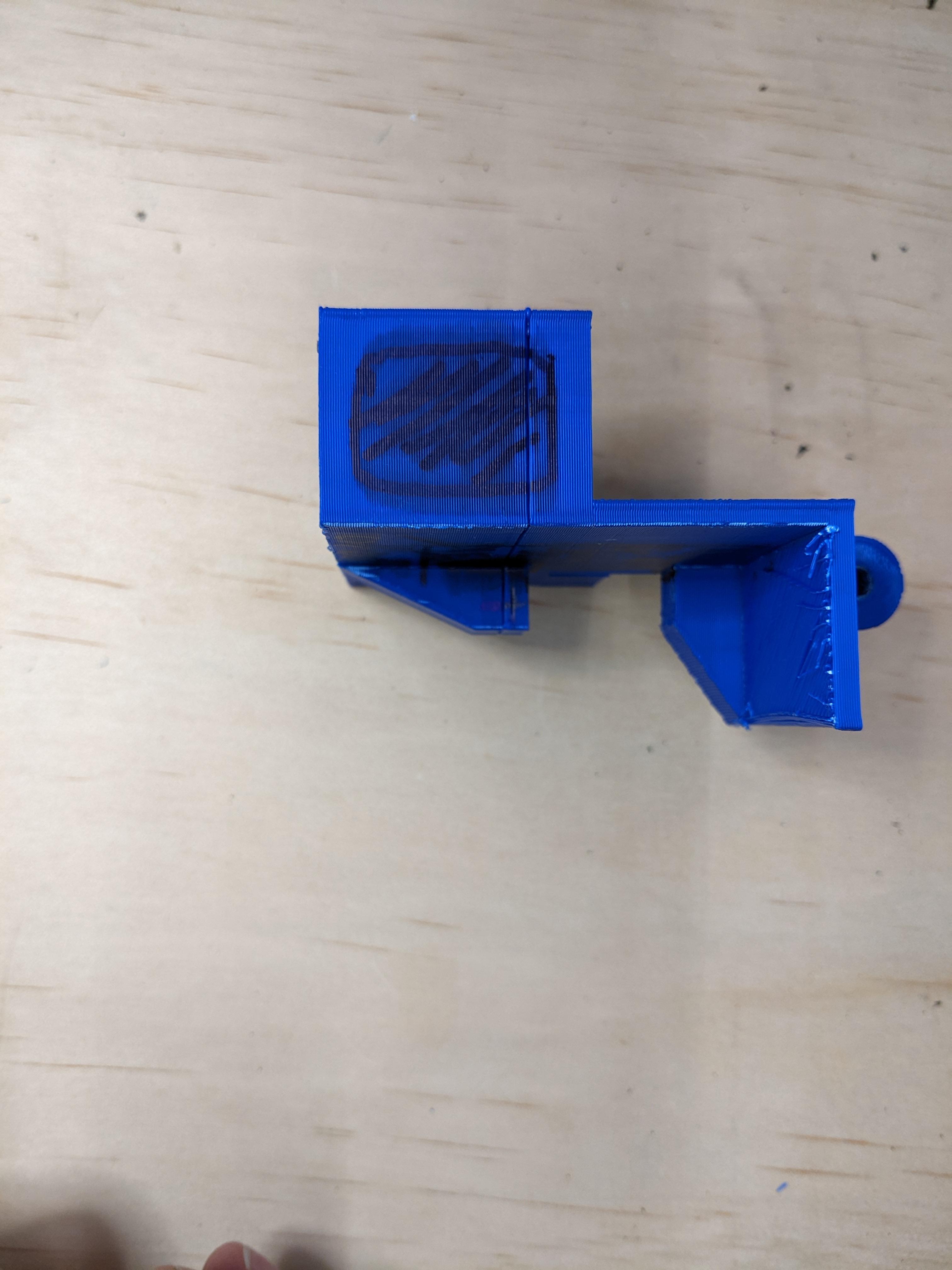
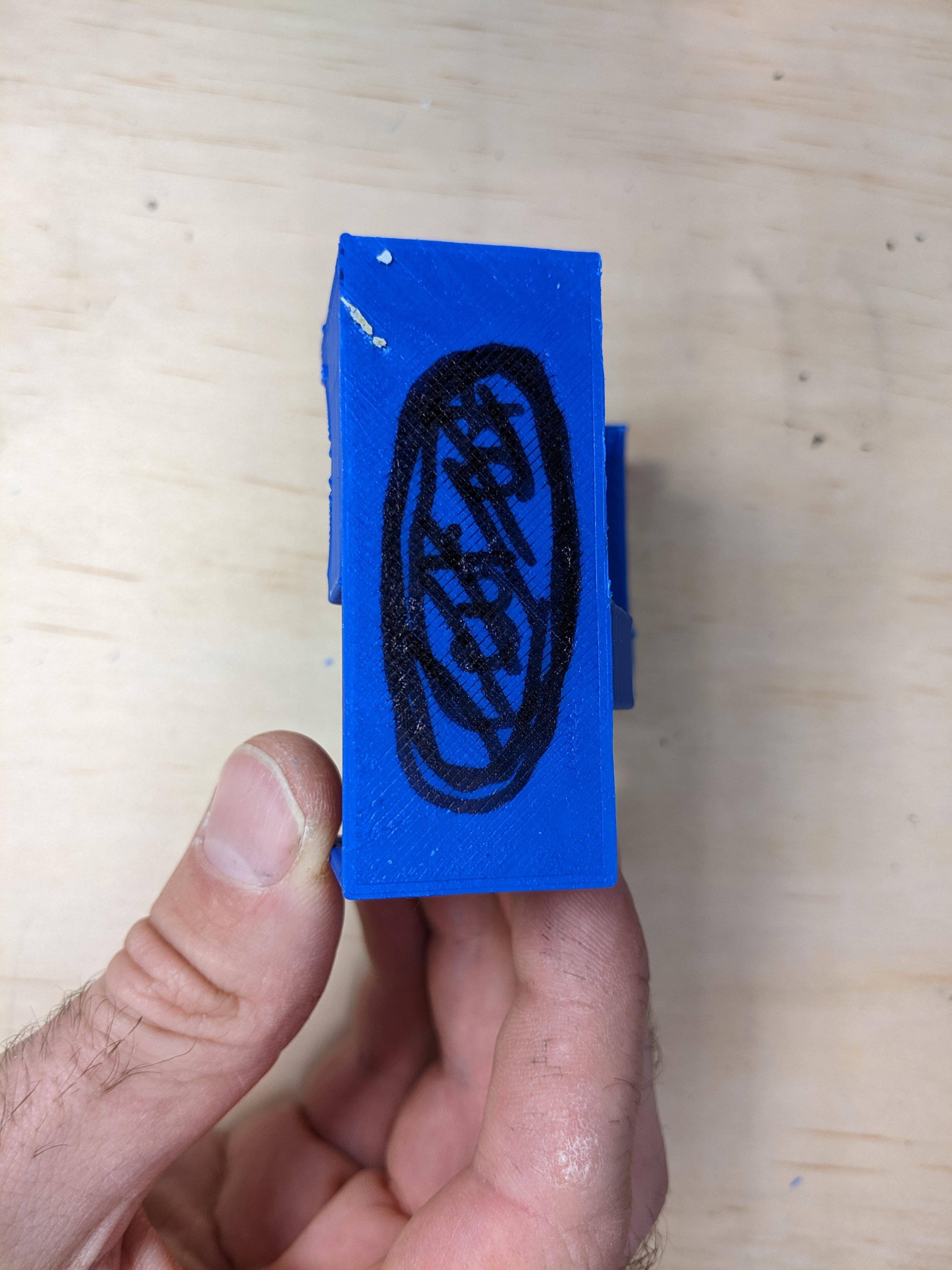
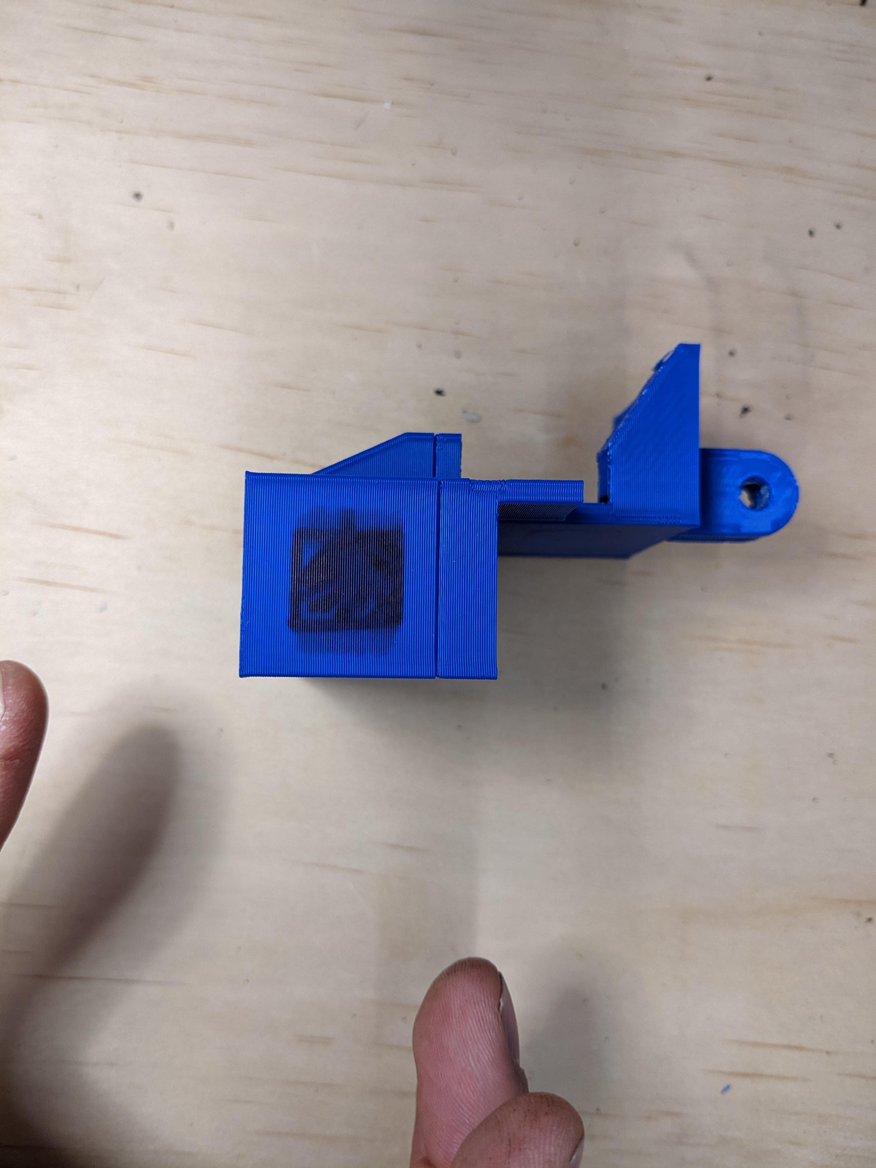
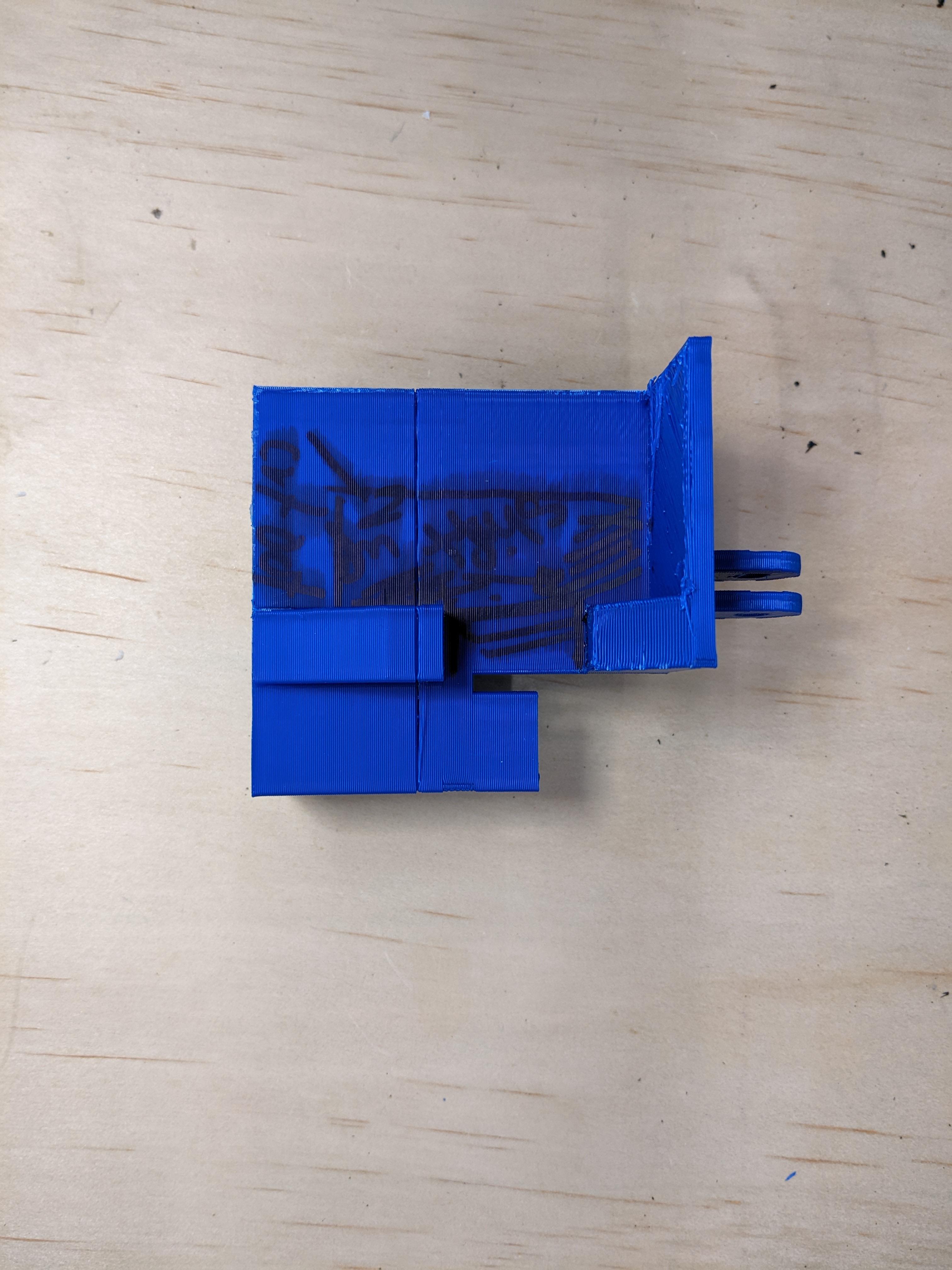
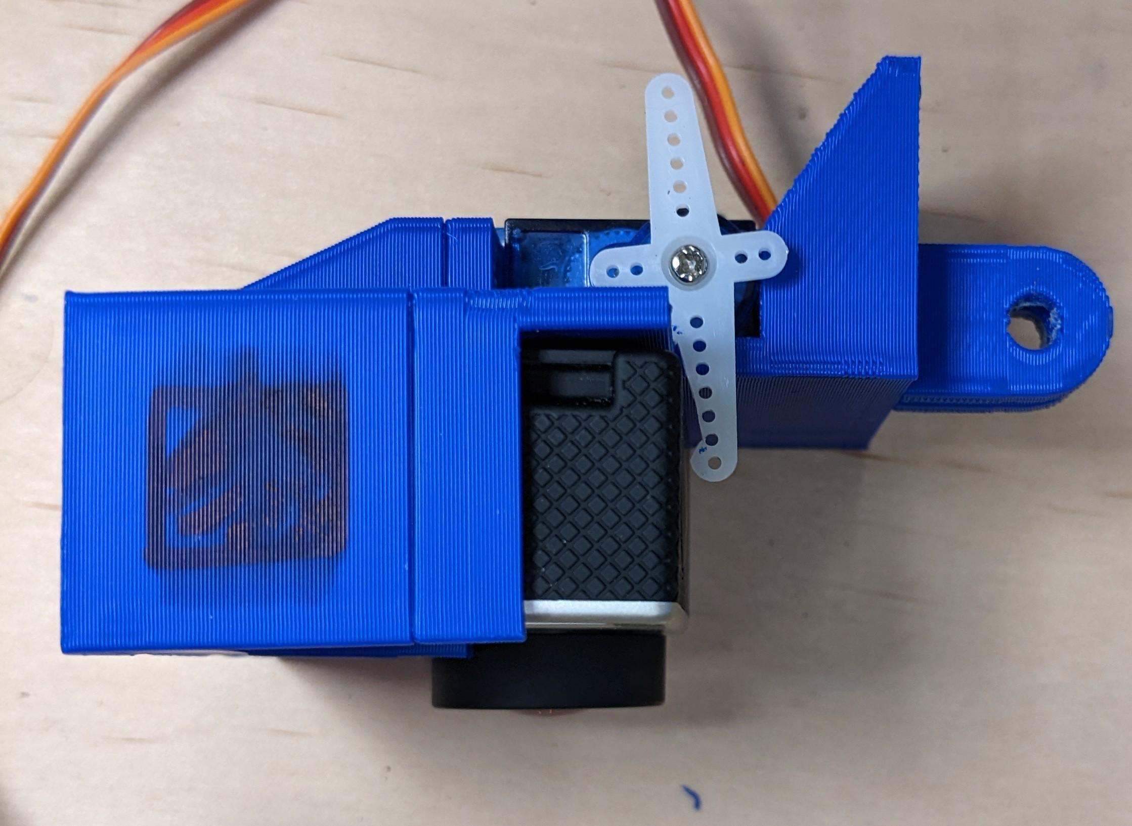
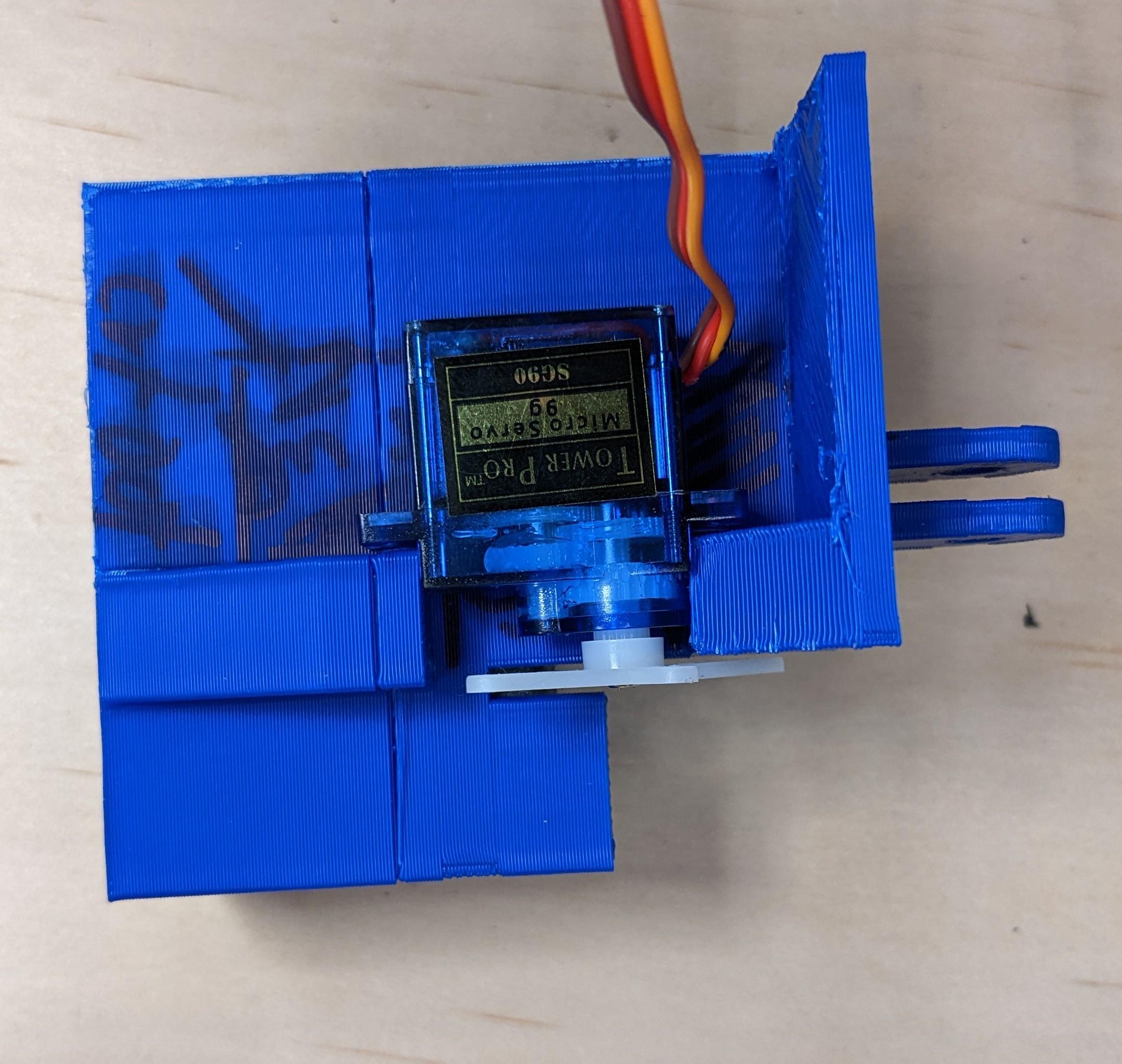
The photos and instructions for this project are for the second iteration/prototype of the housing. I use both versions with the students to show how a first run 'educated guess' is a really valuable process. Working with the students we were able to create a list of changes.
From the first version the changes I made were:
- Add a small round hole for the wifi button
- Reason was, the housing would push on the button and turn it on
- A large hole at the bottom
- Help push out the God pro as the fit was rather snug
- An opening where the microSD card and micro USB ports are
- So I can access this without needing to remove the whole go pro
- Changing where the housing mounts with a go pro mount
- The initial one limited the ability to point 'down' and I needed it to go as far as it could
- Changed how the servo was mounted.
- The servo sat 'on top' of the mounts as opposed to underneath
- This was to make it easier to access the screws
- I added my name to it
- I wanted to play with text and couldn't think up a good name for it
- Increased the void (space where the go pro sits)
- by a mm or two to make it easier to remove
Main Body - the Housing
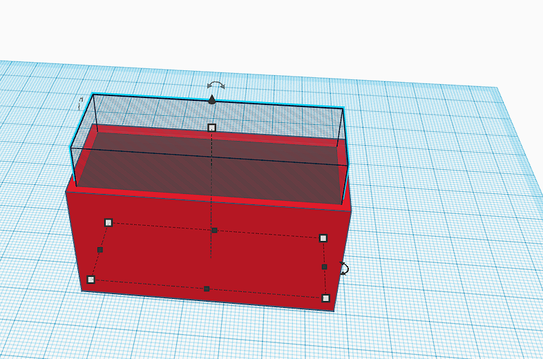
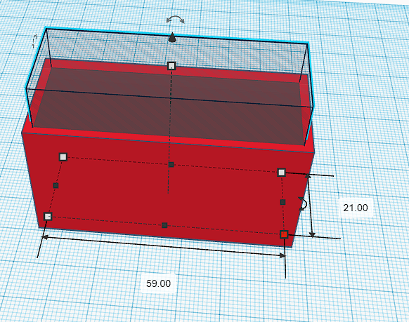
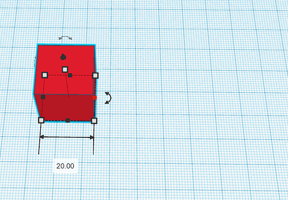
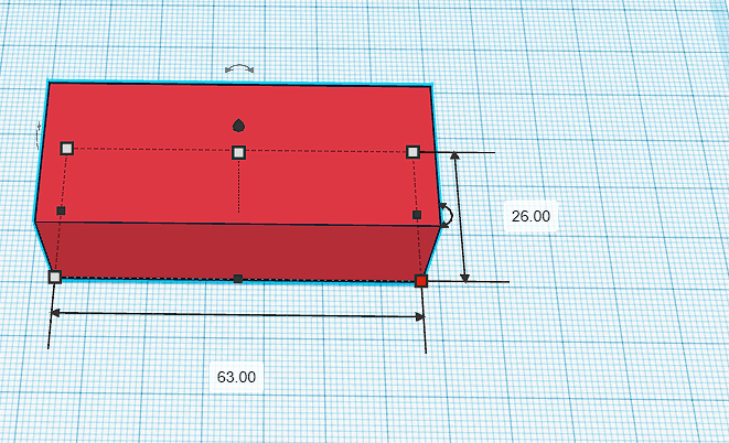
To begin
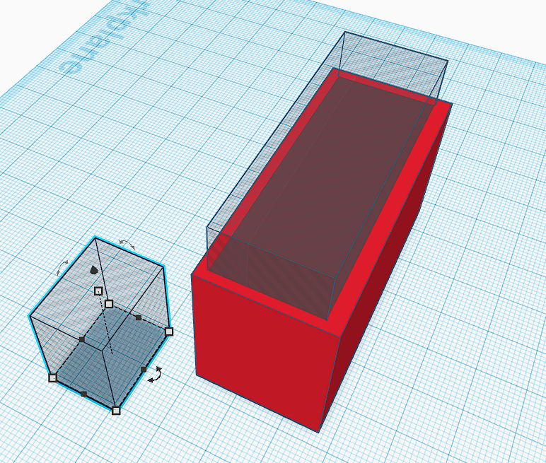
- A cube was dragged and dropped into the main window
- By clicking on the corner of the box (a little dot), the dimension boxes can be changed to required
- This model (red box) was an extra 2mm at the front and sides and 3mm on the back to allow for wall thickness
- Once the main box is right, a shaded cube was dragged in (this is a subtract, or will remove material)
- The void cube was turned into the same dimensions as a go pro 3 with an extra mm to allow for shrinking of plastic (this is where the first prototype assisted)
- To find tune or move the block around, if it's frustrating with the mouse, you can use the arrow keys and it will shift around (depending on what snap to grid setting you have)
Main Body - the 'Windows'
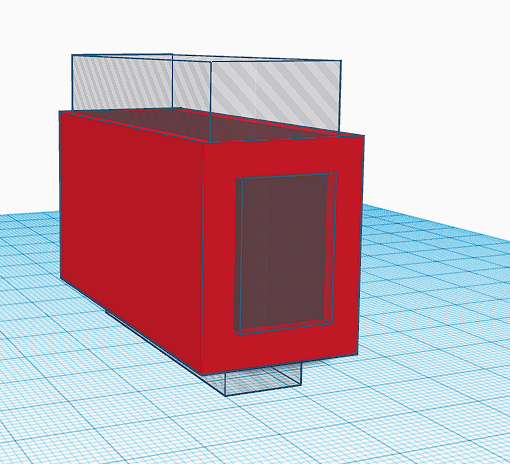
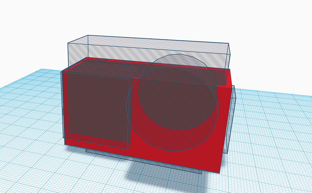
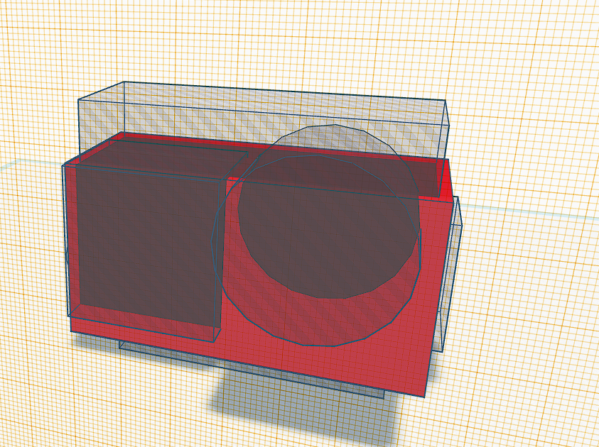
Following the creation of the main body, this step requires all voids
- A cylinder is added for the Wi-Fi button.
- For the cylinder's to be in the right orientation, there are curved arrows. Click on one of those and move your mouse. This will allow for the rotation of the object.
- For this project, all rotations are at 90 degrees, so no approximation is required
- You will require
- 2 cylinders, (Wi-Fi and lens)
- 3 cubes (underneath to push up, front display panel, access to SD card)
- Move the shapes into position, using the arrow keys if you are struggling with the mouse
Servo Mounting Point

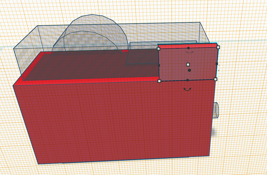
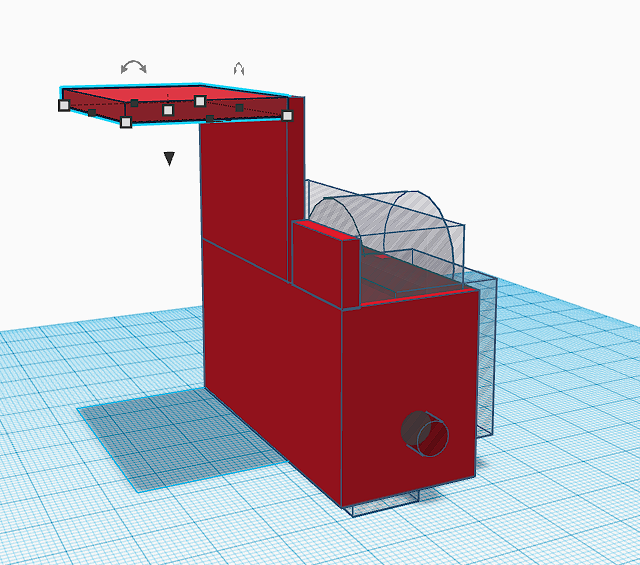
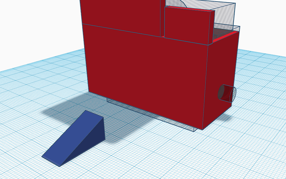
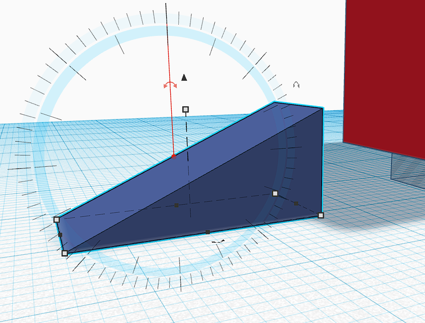
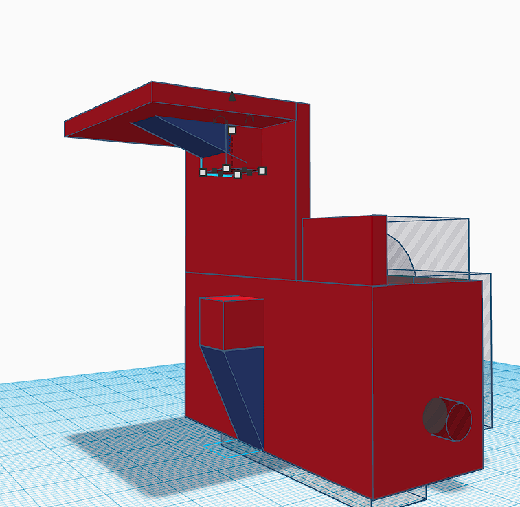
For the servo mounting, there are 7 shapes required
- Two triangular prisms (dark blue), mainly for aesthetics and to add strength without adding too much weight.
- 2 flat cubes for the back, going up vertically. These were 3mm thick and a small space between them to allow for the servo arm to reach between. That space needs to be in line with the GoPro's top button
- 1 flat cube which will have the connection to the mounting point. This is 3mm thick and lays horizontally off of the vertical cube.
- 2 small cubes (roughly 10mm x 9mm x 9mm) for where the servo will screw onto
*To move pieces higher up, use the workplane tool (see image). This means the shapes you create can be placed on the new plane as well as use the arrow keys to move in different directions
Connection to Go Pro Mount
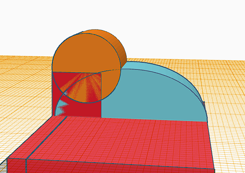
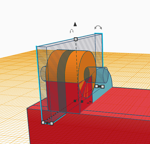
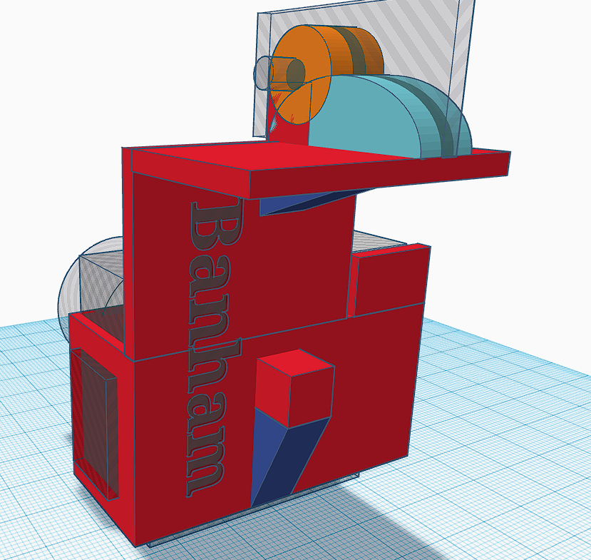
The mounting bracket might be seen as a little bit intimidating but
- 1 semicircle (light blue) which is wide enough for both mounting 'fins' (7 or 8mm)
- 1 cube and circle which are where the bolt of the GoPro mount passes through
- 2 voids
- A cylinder for the location of the GoPro mount bolt
- A cube (long and 3mm wide) placed in the middle of the semicircle to create the 2 'fin' like structures
Optional - Final Print
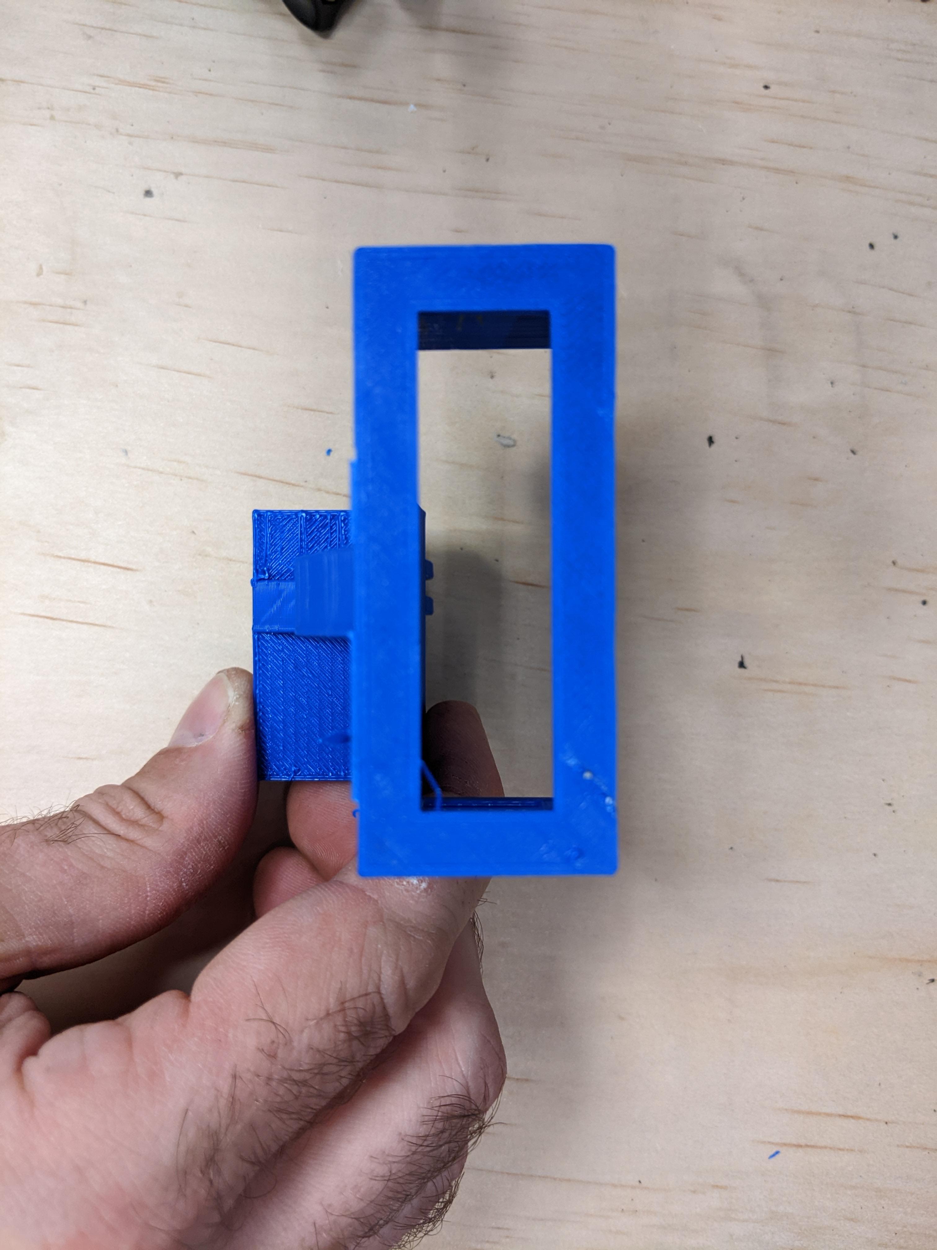
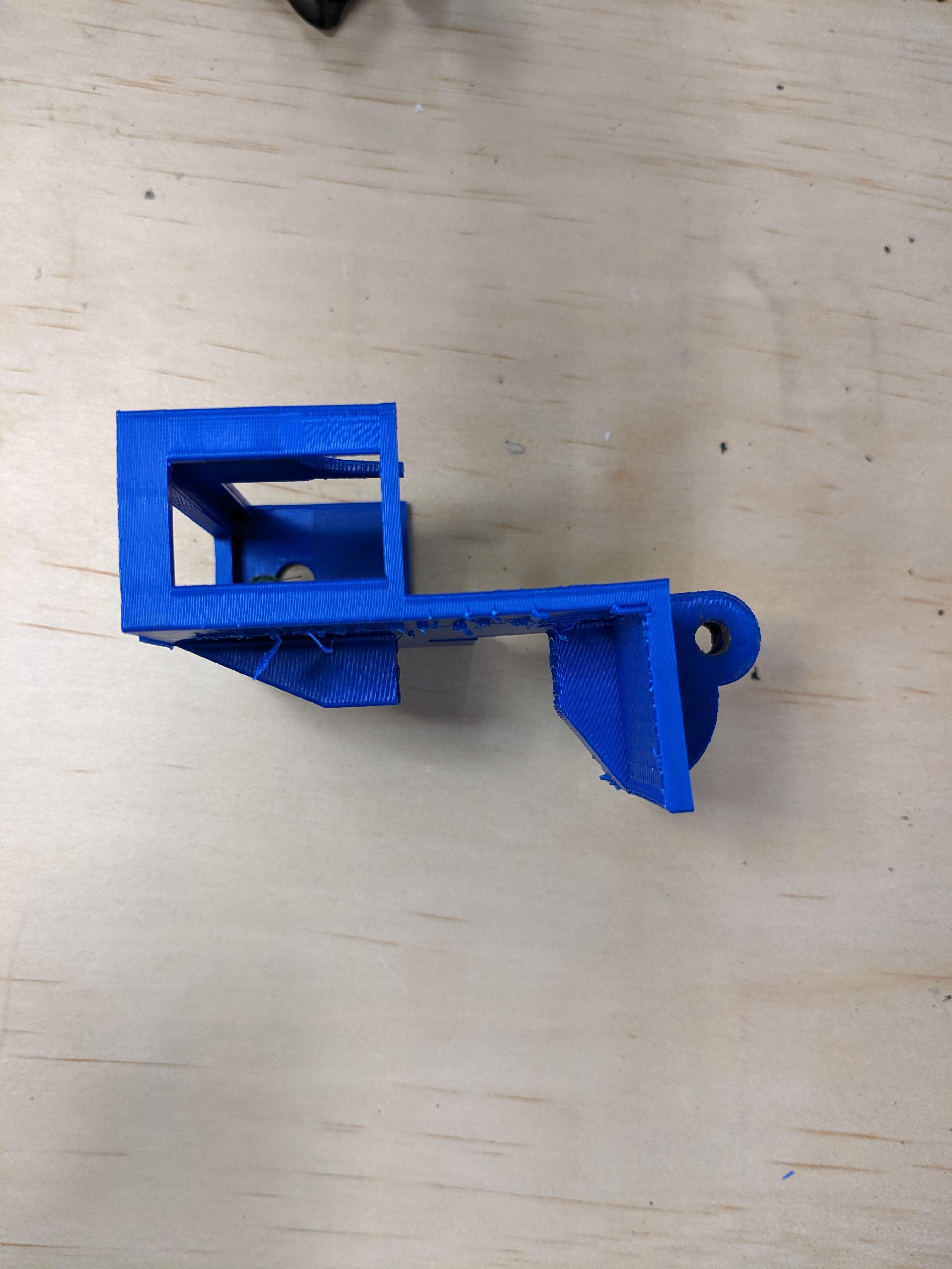
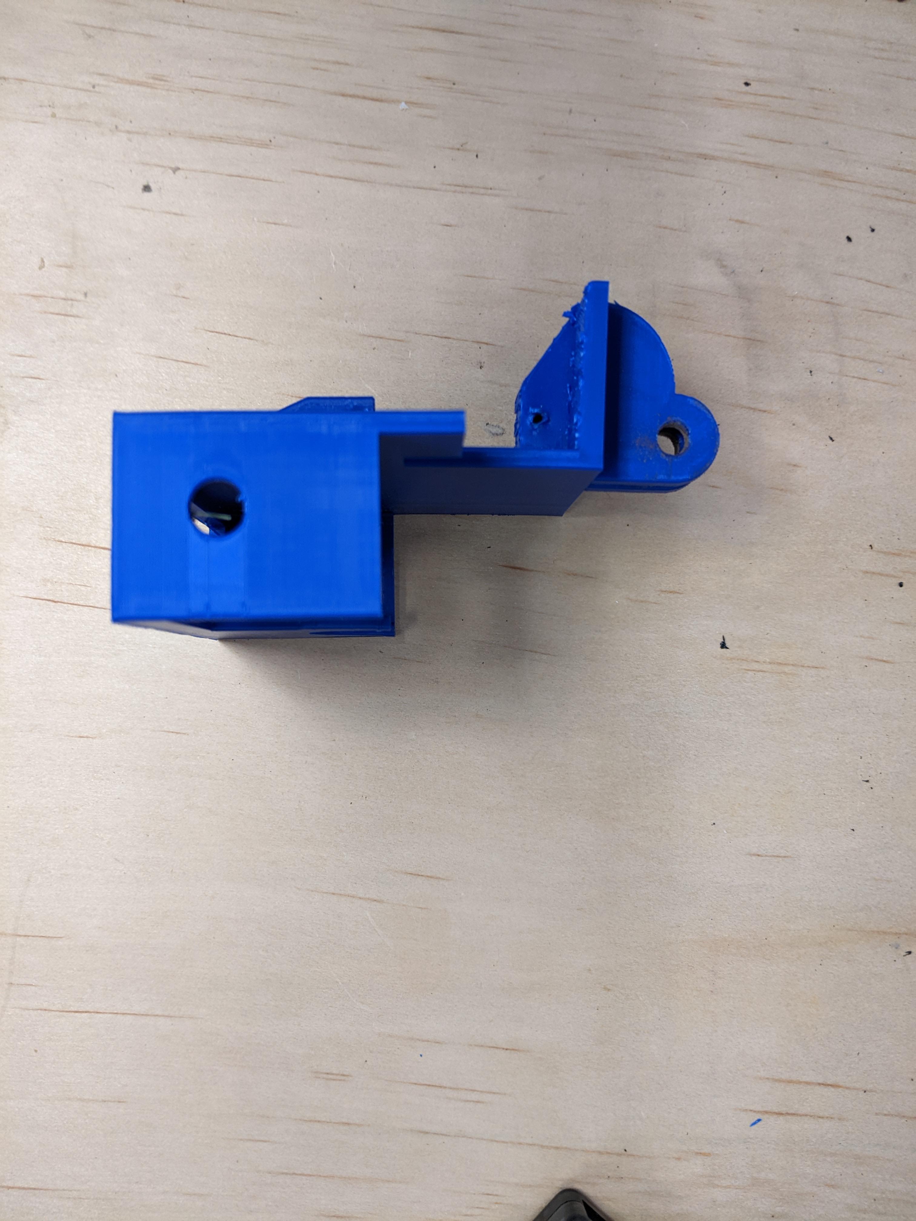
This was printed with blue PLA on an Adventurer 3. This is the result once the supports are removed.
Optional - Fit Out
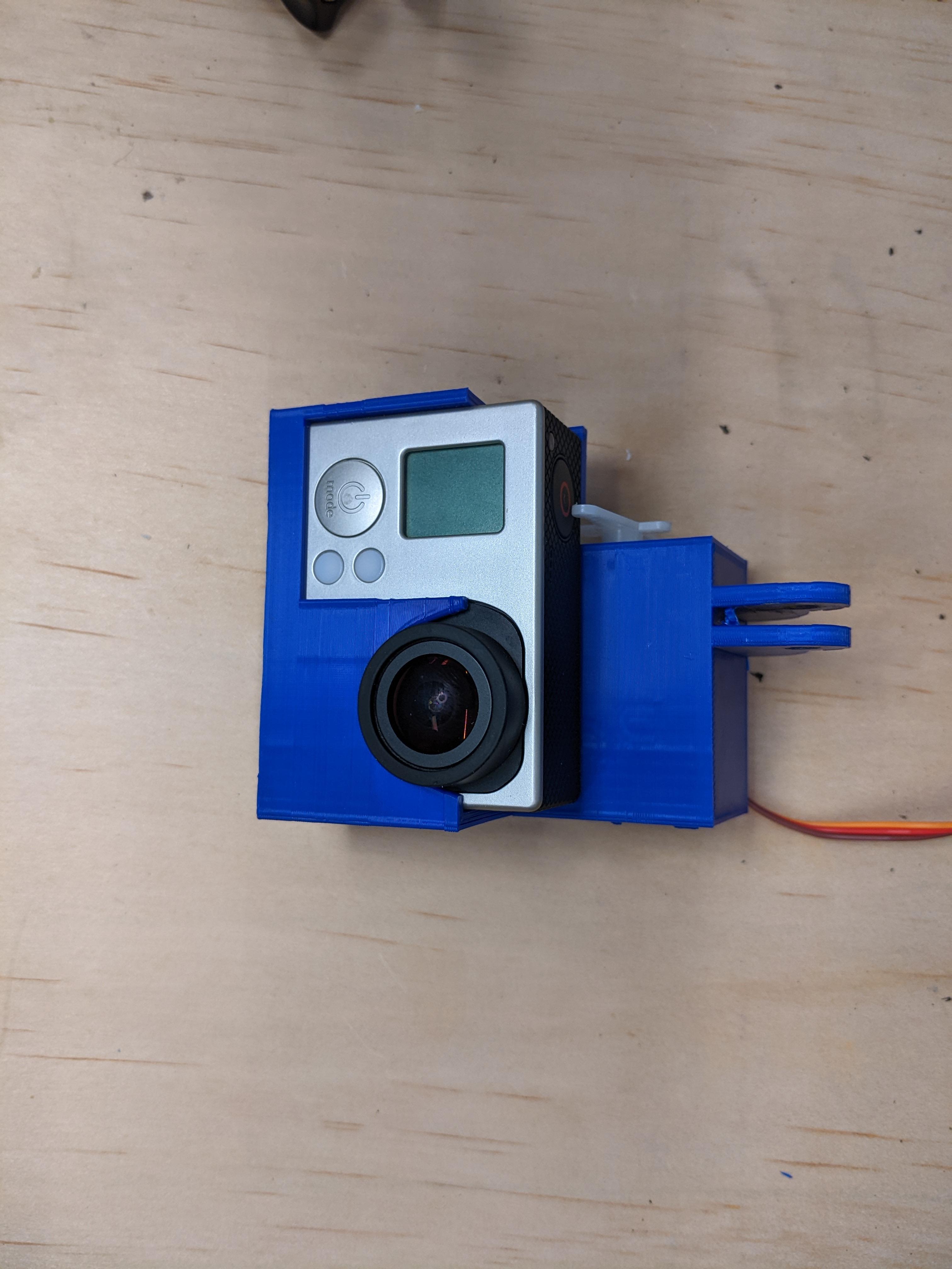
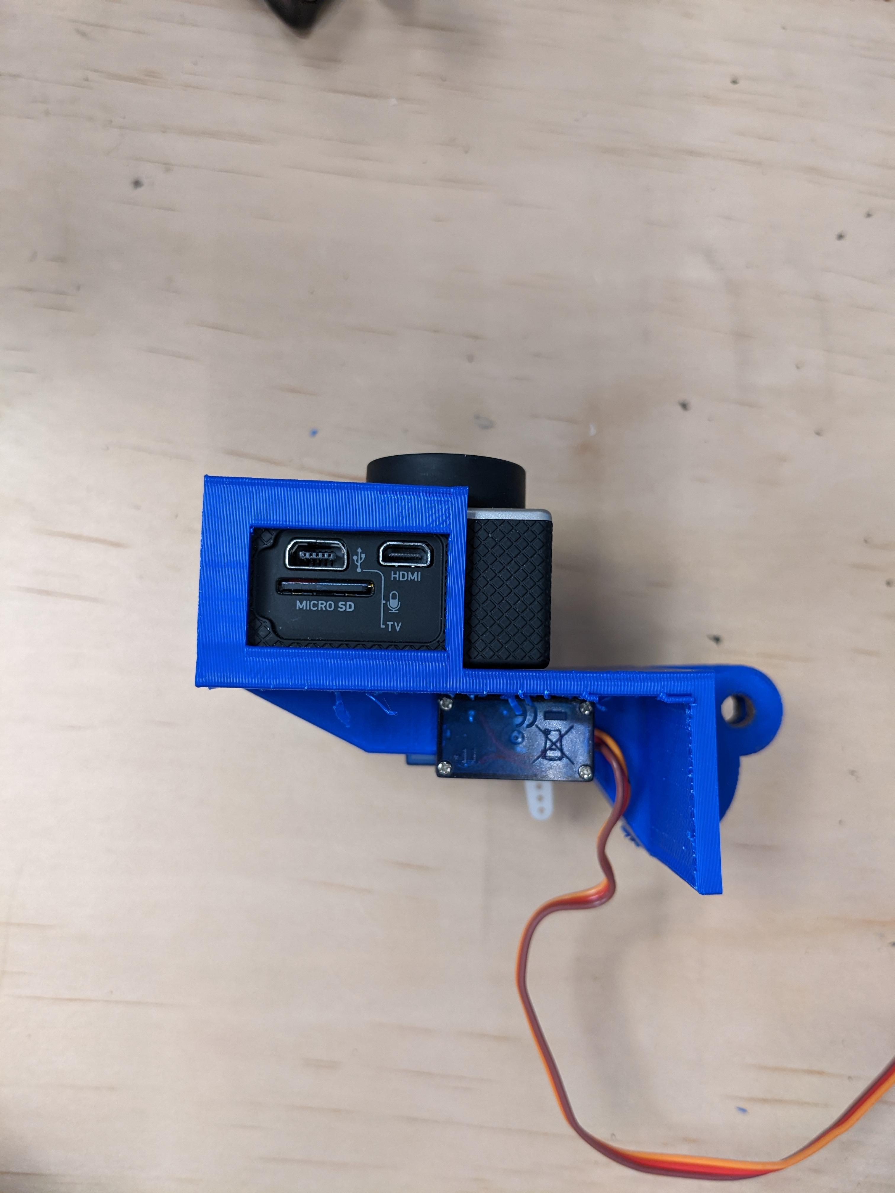
This final stage is when the servo and go pro are inserted to check for fit and function.
The servo arm was trimmed slightly to avoid collision from the first prototype. This may or may not me required for this final version.
I have attached the GoPro Mount here but the measurements might be slightly off. But will hopefully demonstrate the shapes used and the location of them all.
Hopefully this gives you some simple steps to creating your first project in TinkerCad