Timer/Buzzer for Basys 3 in VHDL
by astairs in Circuits > Gadgets
11271 Views, 16 Favorites, 0 Comments
Timer/Buzzer for Basys 3 in VHDL
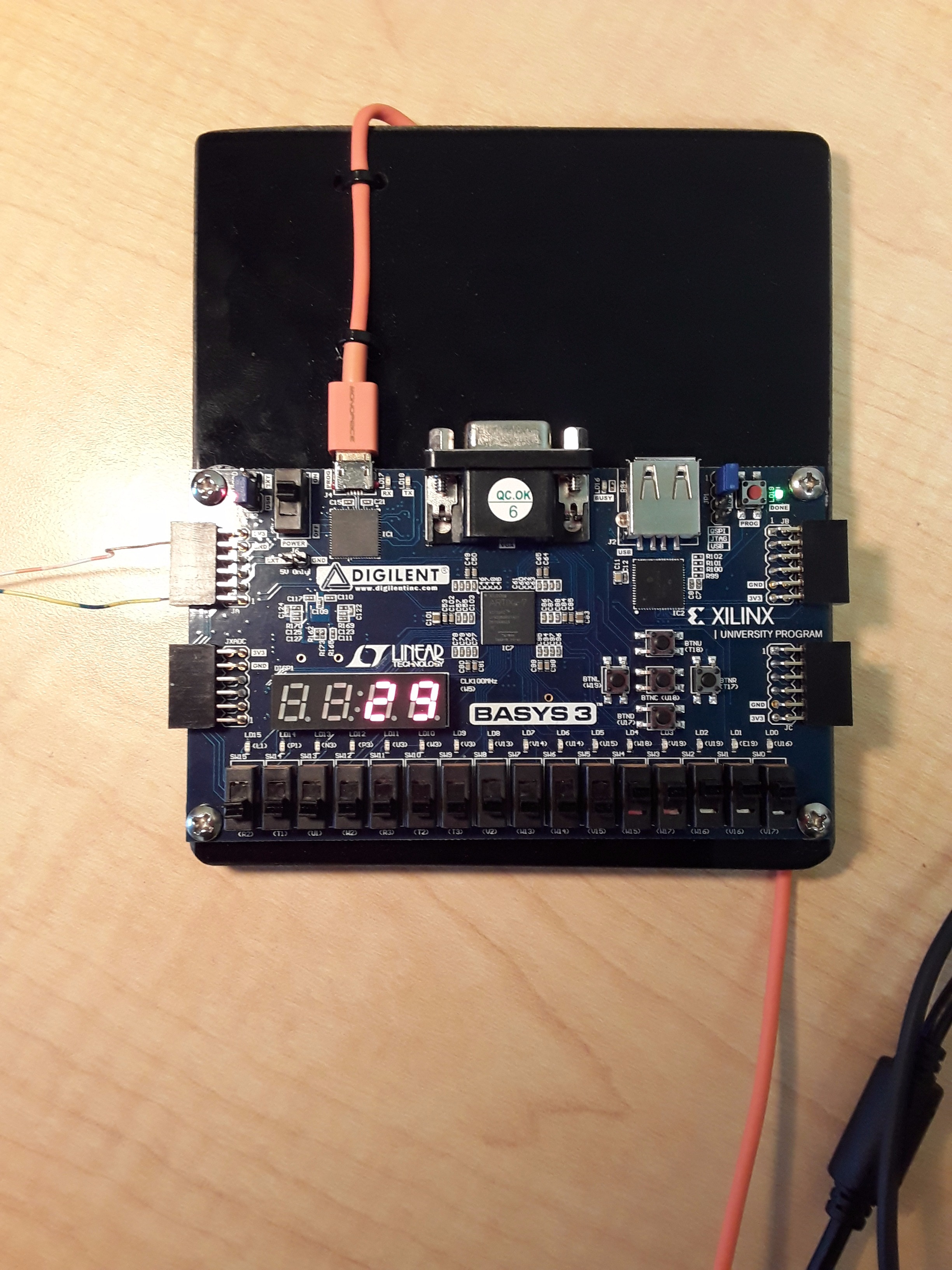
If you’ve ever wanted to make your very own timer, you’re in luck. In this instructable, you will be learning how to create a timer with an external buzzer. These are the things you will need:
1. A Basys 3 Board. You can borrow one from your university or buy one from here. If you’re a student you can receive a discount on the board.
2. USB to Micro USB cable. (Make sure your cable isn’t just a charging cable and that it can transmit data.)
3. An external speaker or buzzer such as the “adafruit piezo speaker”.
4. Small copper wires (insulation stripped at ends) to connect the speaker to the Basys 3.
5. Vivado 2014.2 or newer. Vivado can be installed for free online. Once you have obtained all the necessary hardware and software, you can proceed to the next step.
How It Works
If you want to know a little bit about how this code works, go ahead and read this simple overview section. If you would rather simply install the code, you can skip this step. (Code is in the next step)
Initially, we were going to going to create a timer/stopwatch that would record laps. We had written some of the code but due to time constraints we decided on creating a timer.
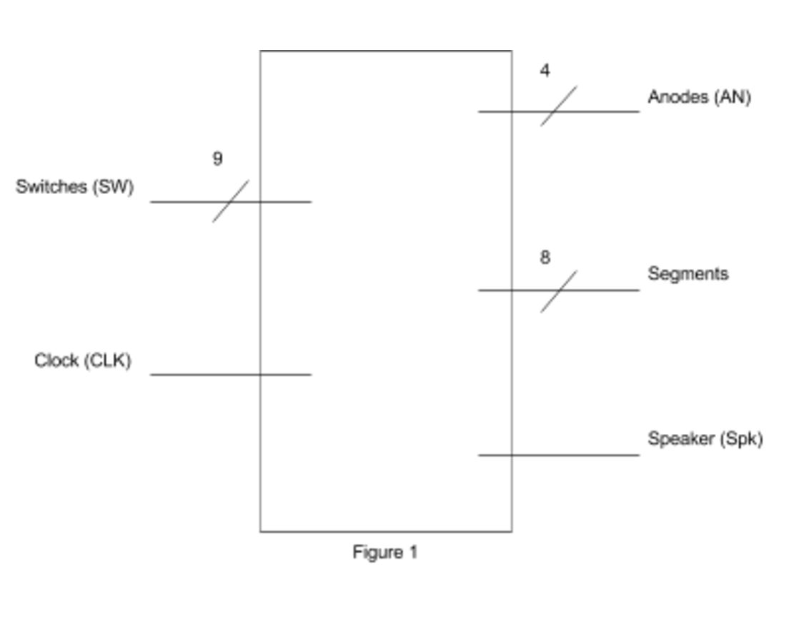
In figure 1, we have a top level block diagram showing all the inputs and outputs.
Inputs: There are 9 switches used on the board. The leftmost switch is to pause/start the timer. The rightmost eight switches are used to set the time in binary. Another input is the clock on the basys 3 board.
Outputs: “Segments” refers to the 7-segment display on the basys 3 board. There are 8 bits because the display also includes a small dot to the right of every number. Anodes refers to the anodes corresponding to each of the four full “digits” on the 7-segment display. These turn each individual 7-segment display on or off.
In this code there is one top module and multiple submodules. While we wrote many of the submodules and the main module, we decided to use some external code. For the siren, the code obtained was written in Verilog. The rest of the code is in VHDL Here is what these modules are and what they do.
Main Module: This brings together the following modules.
my_clk_div: These modules divide the clock frequency to slow it down. All modules with "clk_div" are based on this code by Bryan Mealy.
timer: This pauses the time when a switch is flipped up.
sseg_dec: This sets the seven segment display depending on how the switches are configured. Code available here by Bryan Mealy.
mux: The multiplexer used in several of the modules.
siren: Code for outputting a siren sound from fpga4fun.
bin2bcdconv: Converts binary to decimal, since the switches will input in binary. Code available here by Bryan Mealy.
Putting Hardware and Software Parts Together
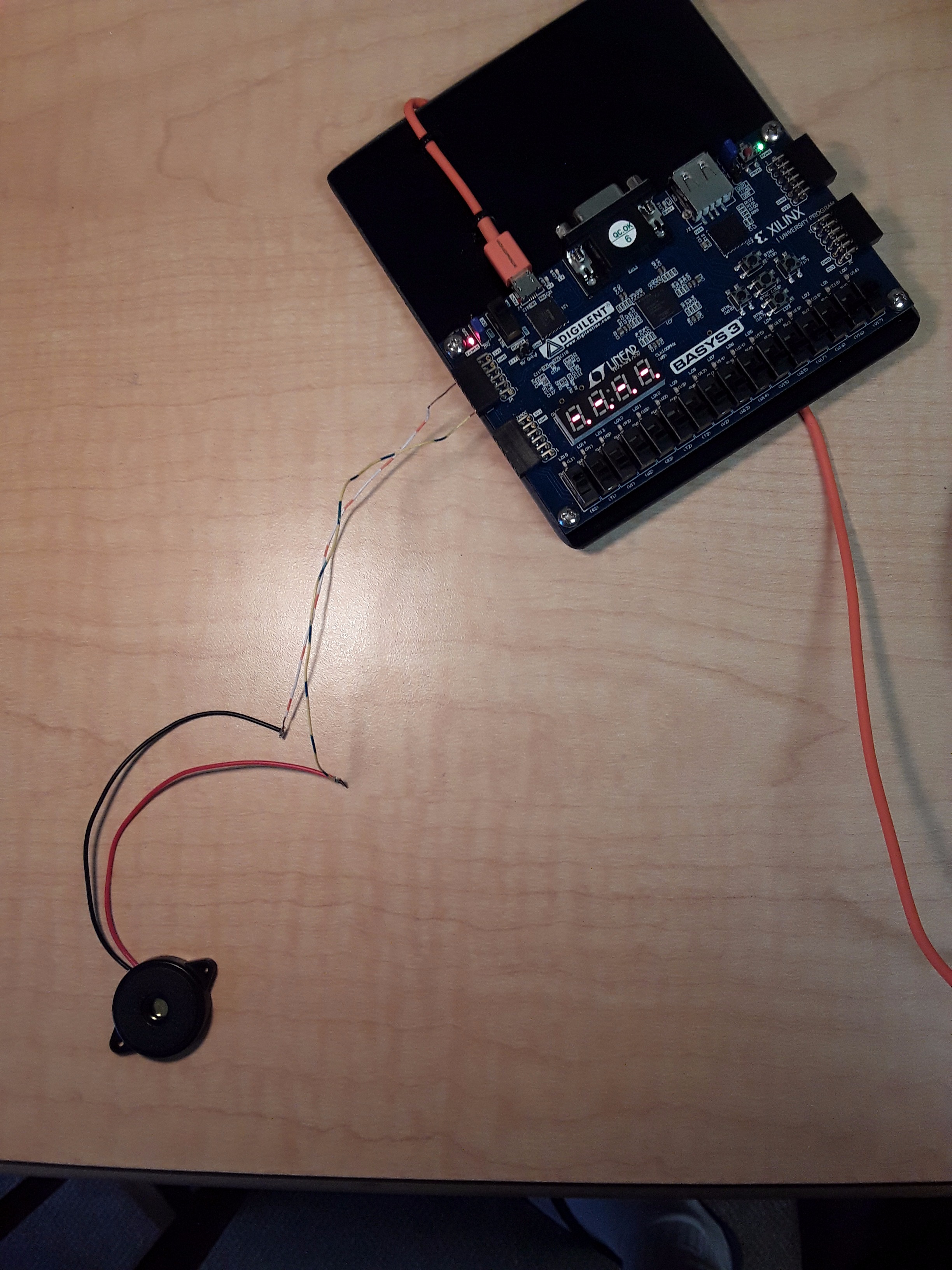
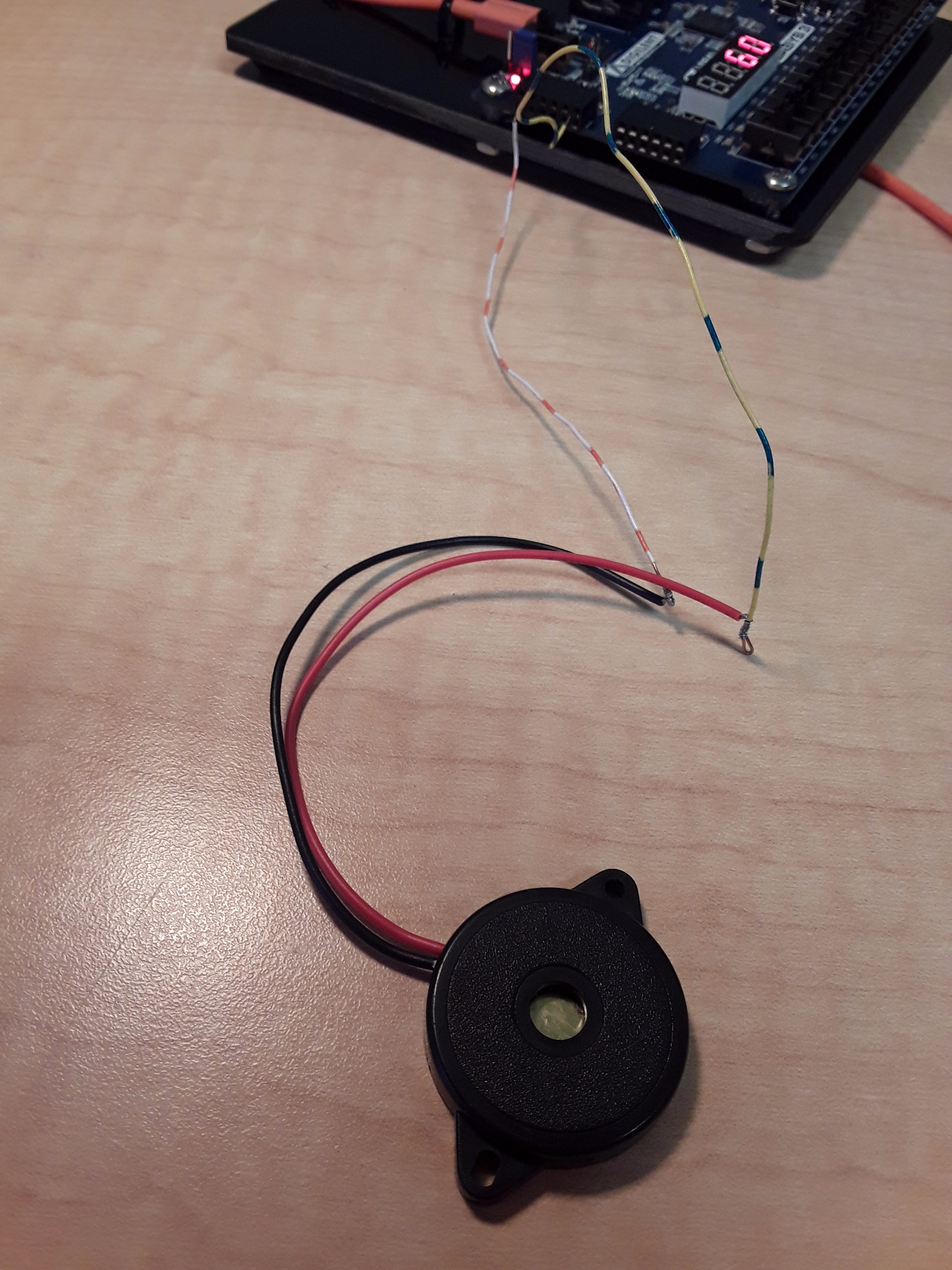
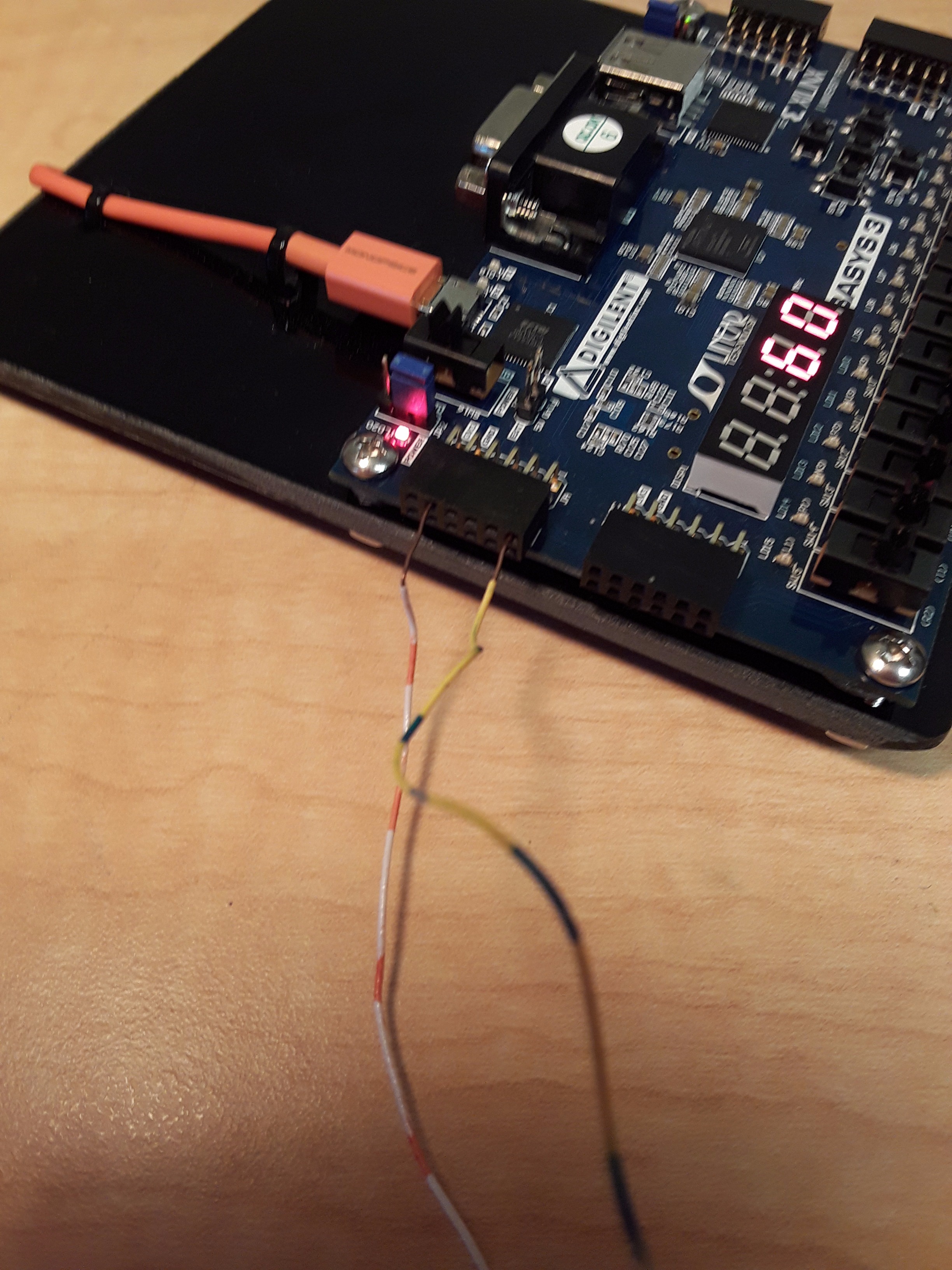
This step requires wiring the speaker to the specified ground port and Pmod port in your custom constraints file. The constraints file for this project uses J1. (Place caution, because not all speakers will work well with the Basys 3 board. Make certain the black wire goes to ground.) Therefor, if you use our code place the positive wire in the J1 slot and the negative to the ground.
Have the Basys 3 board plugged into a computer with the USB to Micro USB cable. Flip the power switch for the Basys 3 board and have it connect to Vivado. You will learn how to program the device in the next step.
Programming Your Basys 3 Board
Before using Vivado, it is important to understand where all VHDL/Verilog files are to be stored and how they will be accessed. The link below provides a thorough tutorial and reference for using Vivado effectively for this project and future projects.
You can download the attached ".zip" file and unzip it. You should now be able to open Vivado then select "File => Open Project" and select the files. If you have issues opening the file feel free to message me through instructables.
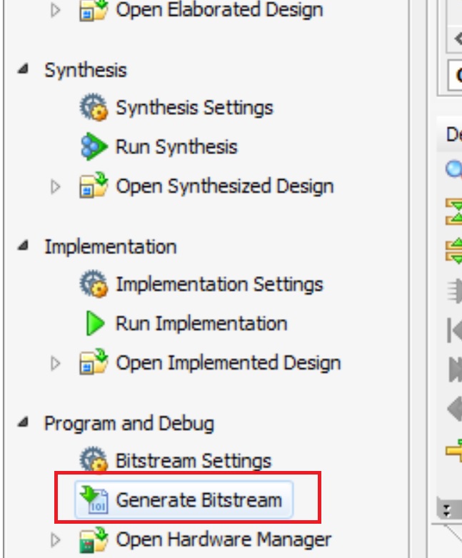
If the bitstream is not already written, click “Generate Bitstream” under left menu to have Vivado undergo synthesis, implementation, and bitstream writing. Each of these processes has a function, but for our purposes using “Generate Bitstream” is sufficient.
How to Use It
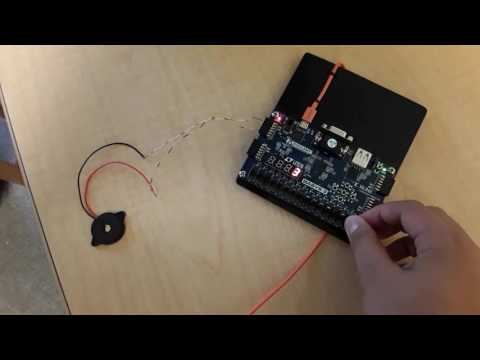
To operate the timer, we use SW15 and the eight rightmost switches (SW7, SW6, SW5, SW4, SW3, … SW0).
The rightmost switches act as the 8 bit binary input, you flip the switches up to make them a "1". The timer will count down from the user input as seconds in decimal. The maximum value for this project will be 256. Therefore, any value between 0 and 255 seconds can be input by the user for this timer. SW15 acts as the resume/pause switch for the timer. When it is flipped on, the timer will proceed to count down as shown on its seven segment display. When it is off, the timer will ‘hold’ the last value displayed. When the timer goes off, the buzzer will sound. The simultaneous ‘buzz’ and ‘siren’ emulates a bird call.
The video demonstrates this.
(This project was created for Cal Poly's CPE 133 class)