TimeRuler
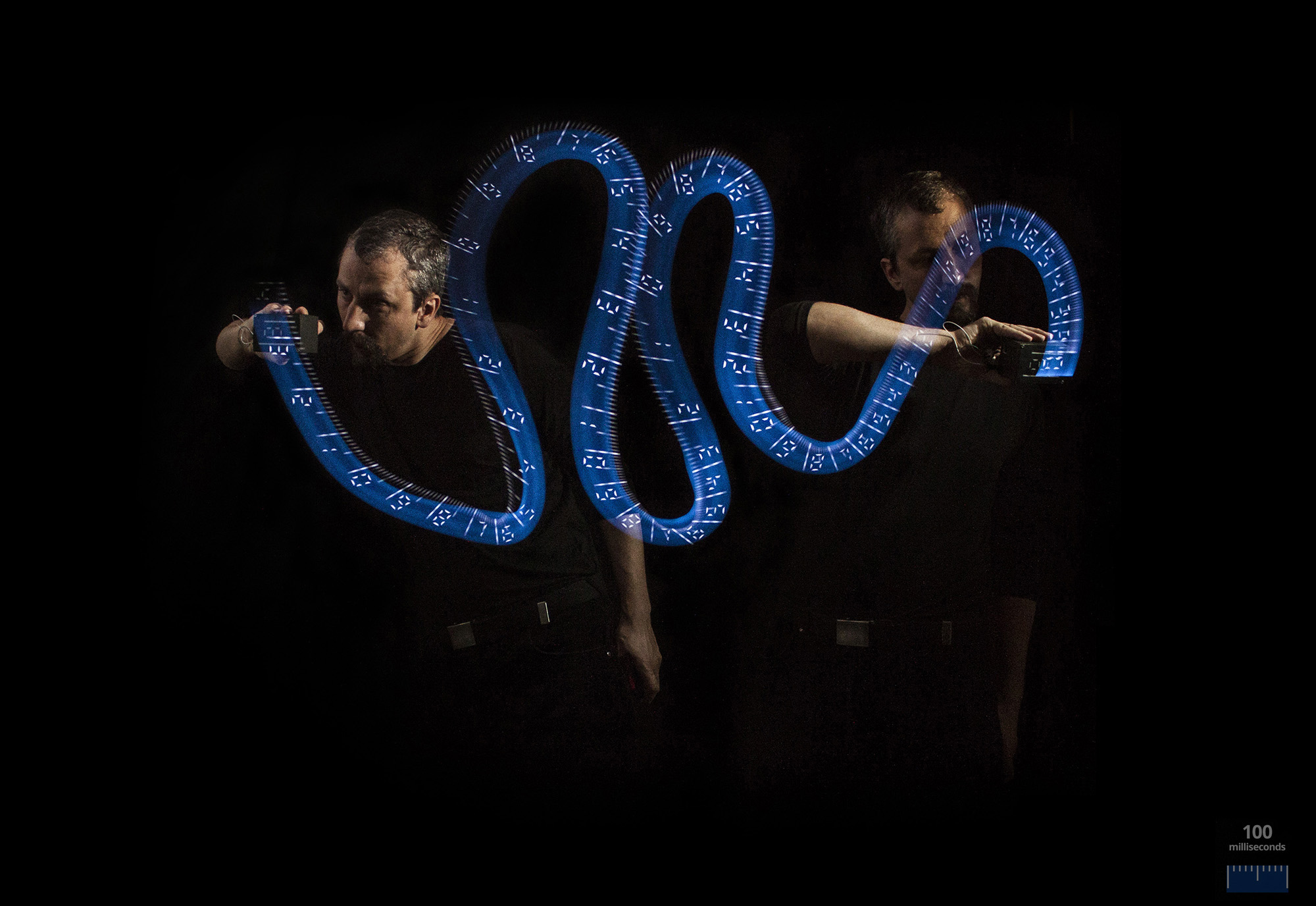
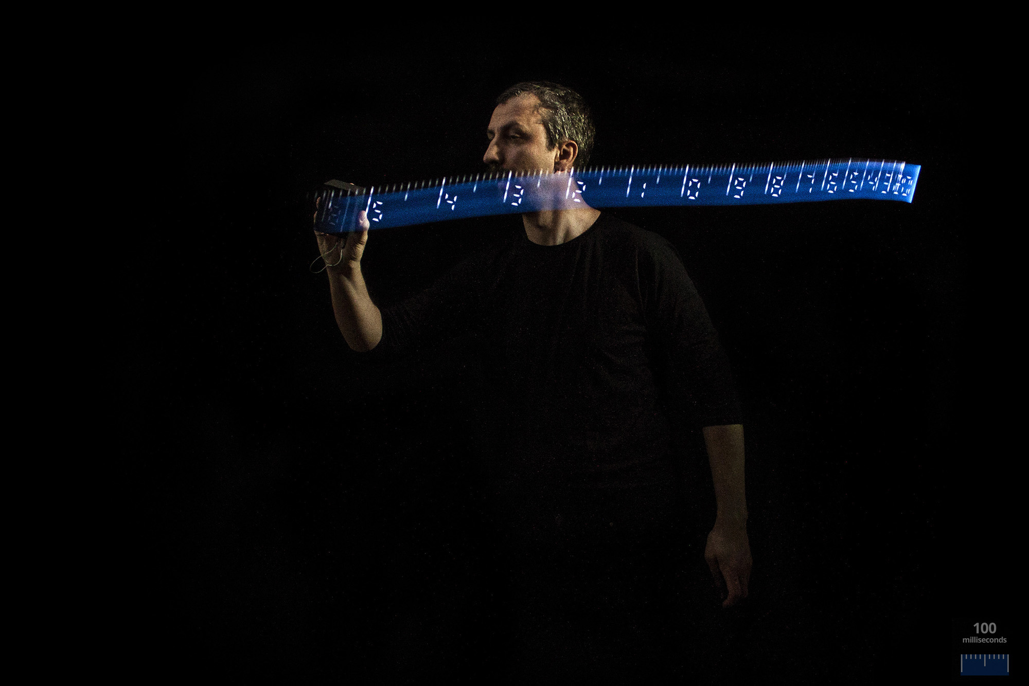
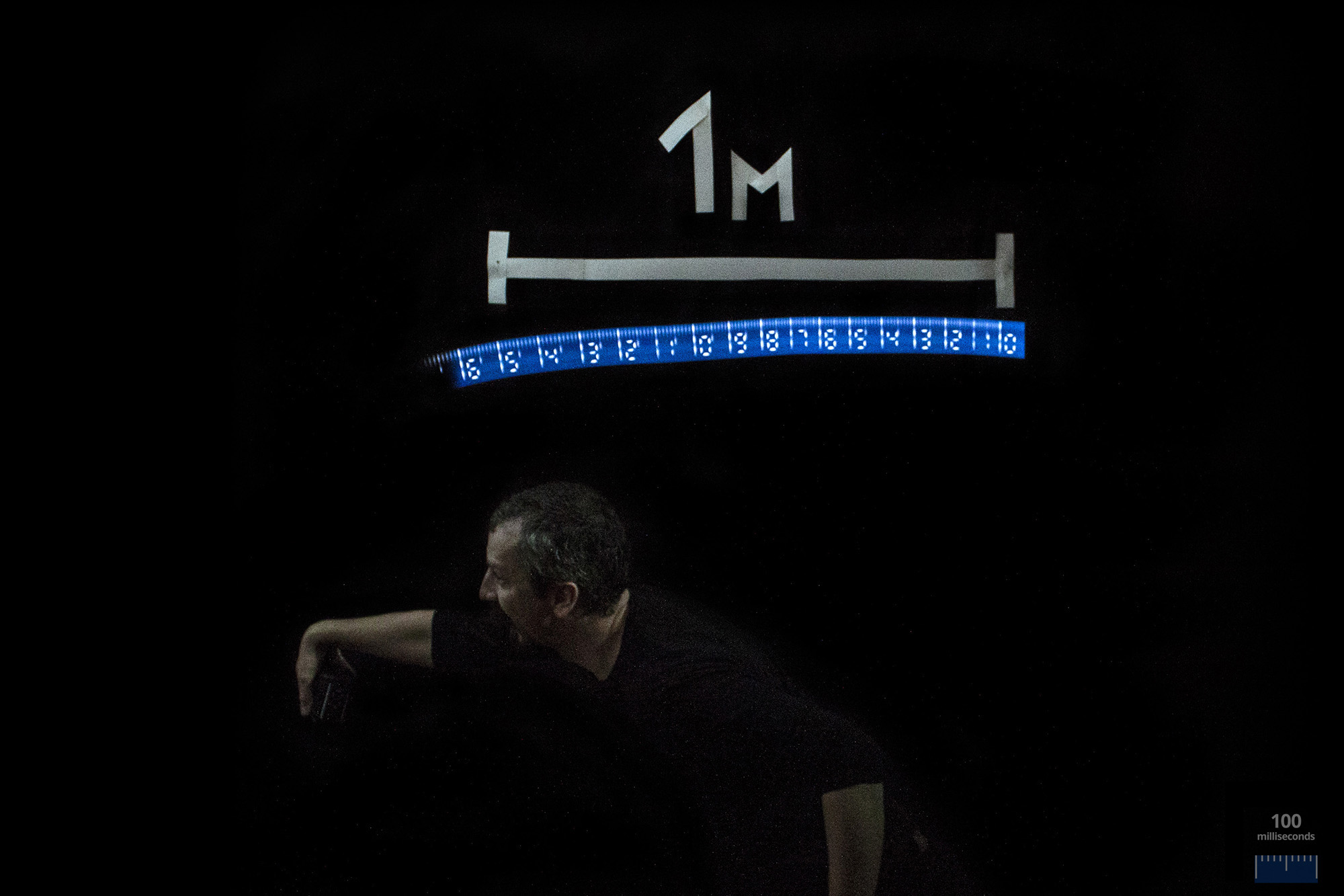
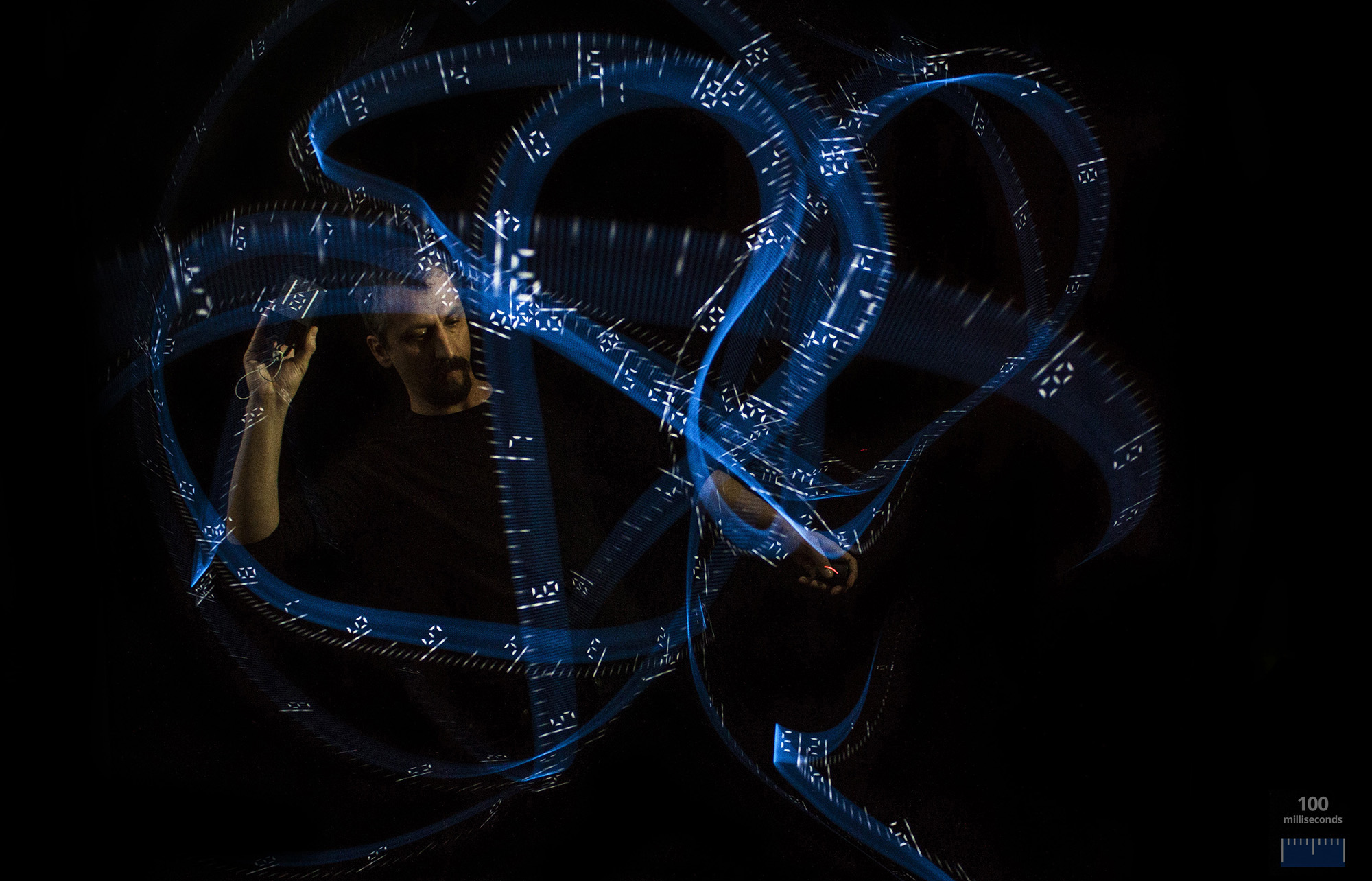
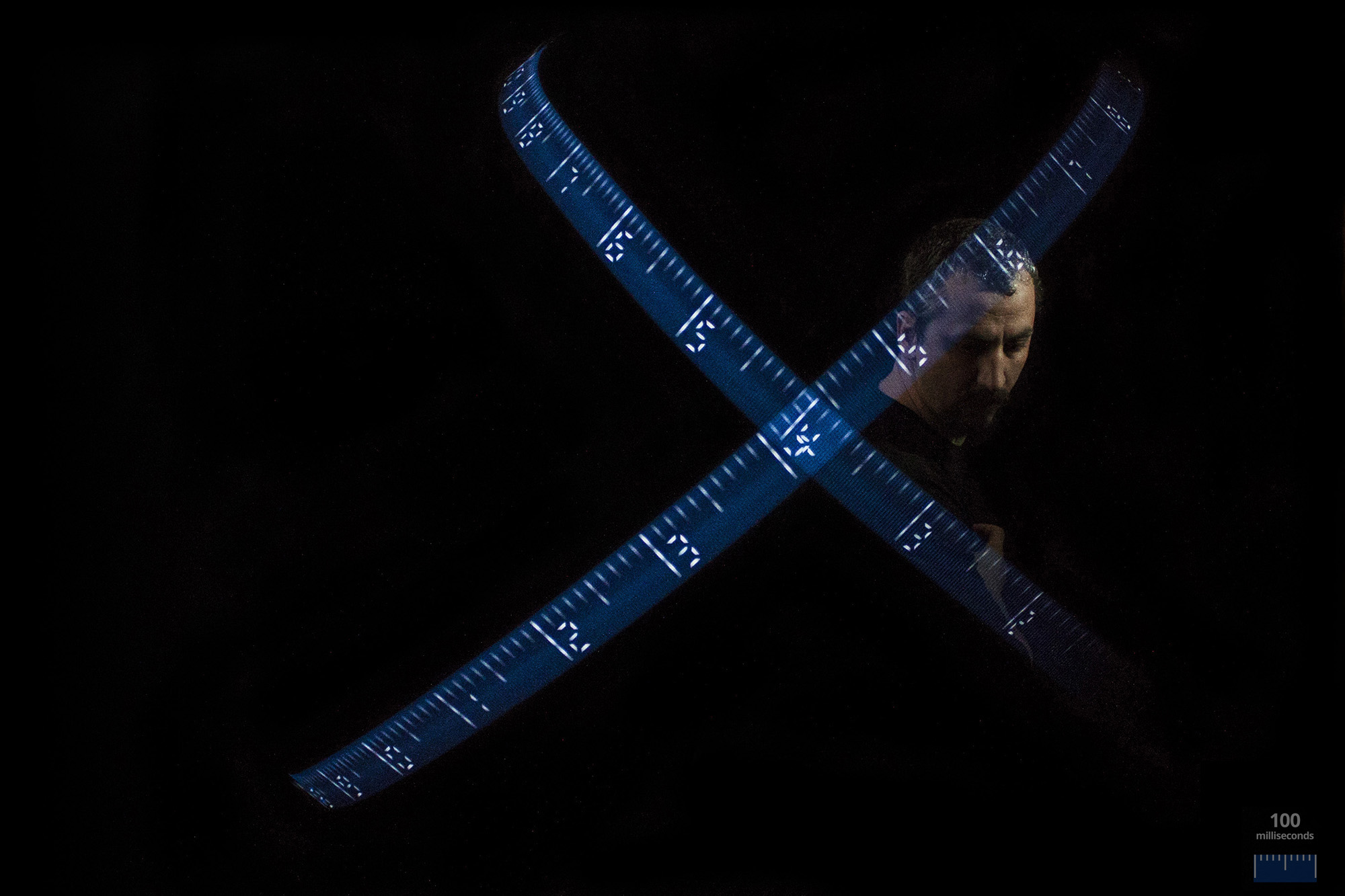
TimeRuler is a time-space measuring tool, using light-painting technique. It can be used for fun, for measuring high speed movement in different sports or as an educational device for schools.
What you need:
- Arduino UNO, or similar
- 13 pcs. 3V ultra bright dome LED
- jump wire
- mini breadboard
- 9V battery
- plywood
- wood adhesive
- glue gun
- tracing paper, black cardboard, carbon paper
- silver paint or mirror sheets
- fretsaw
- Camera with long exposure function
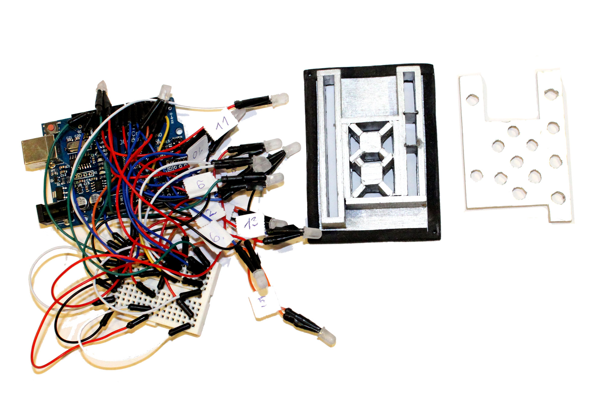
Wiring, Testing
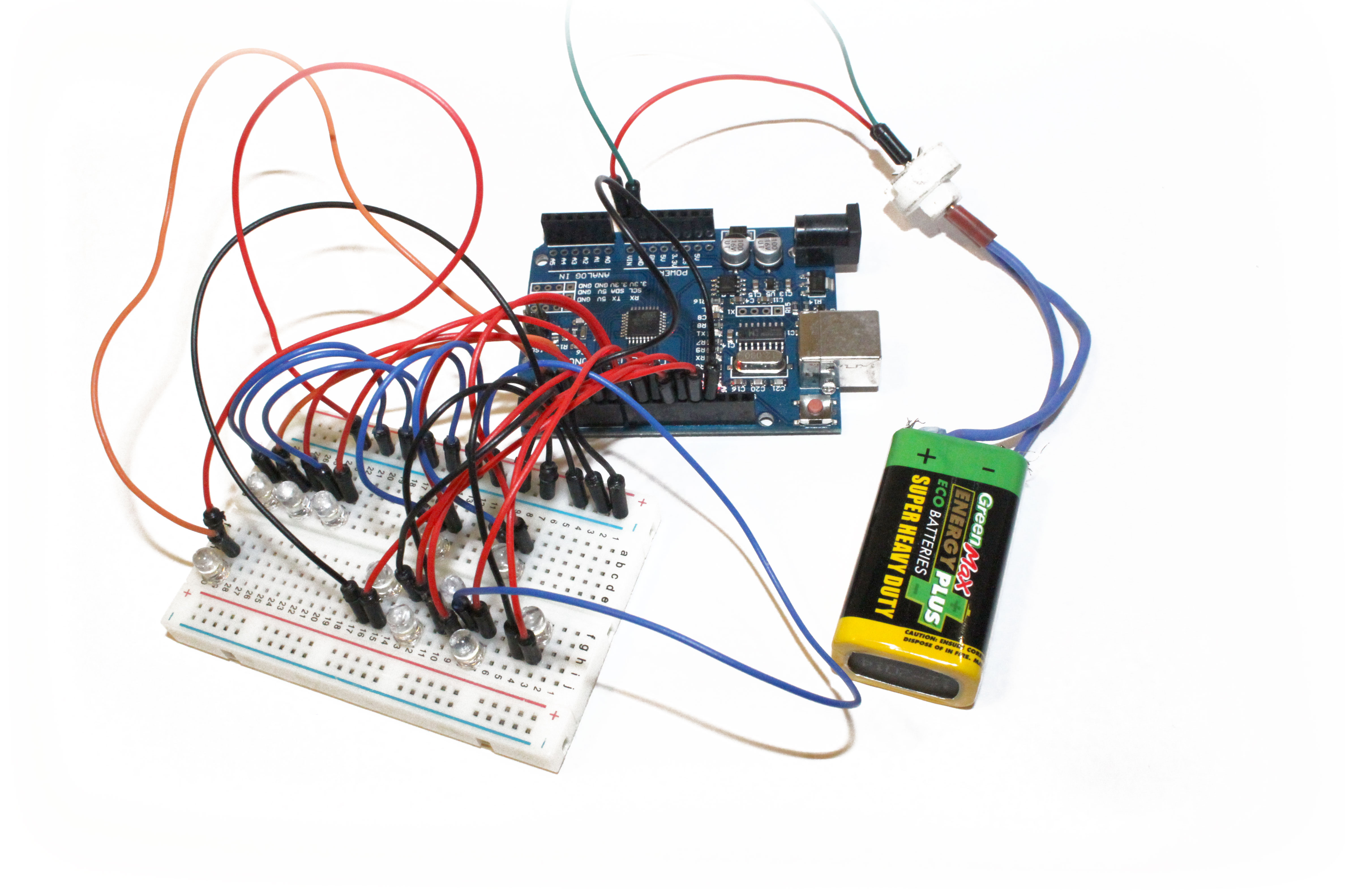
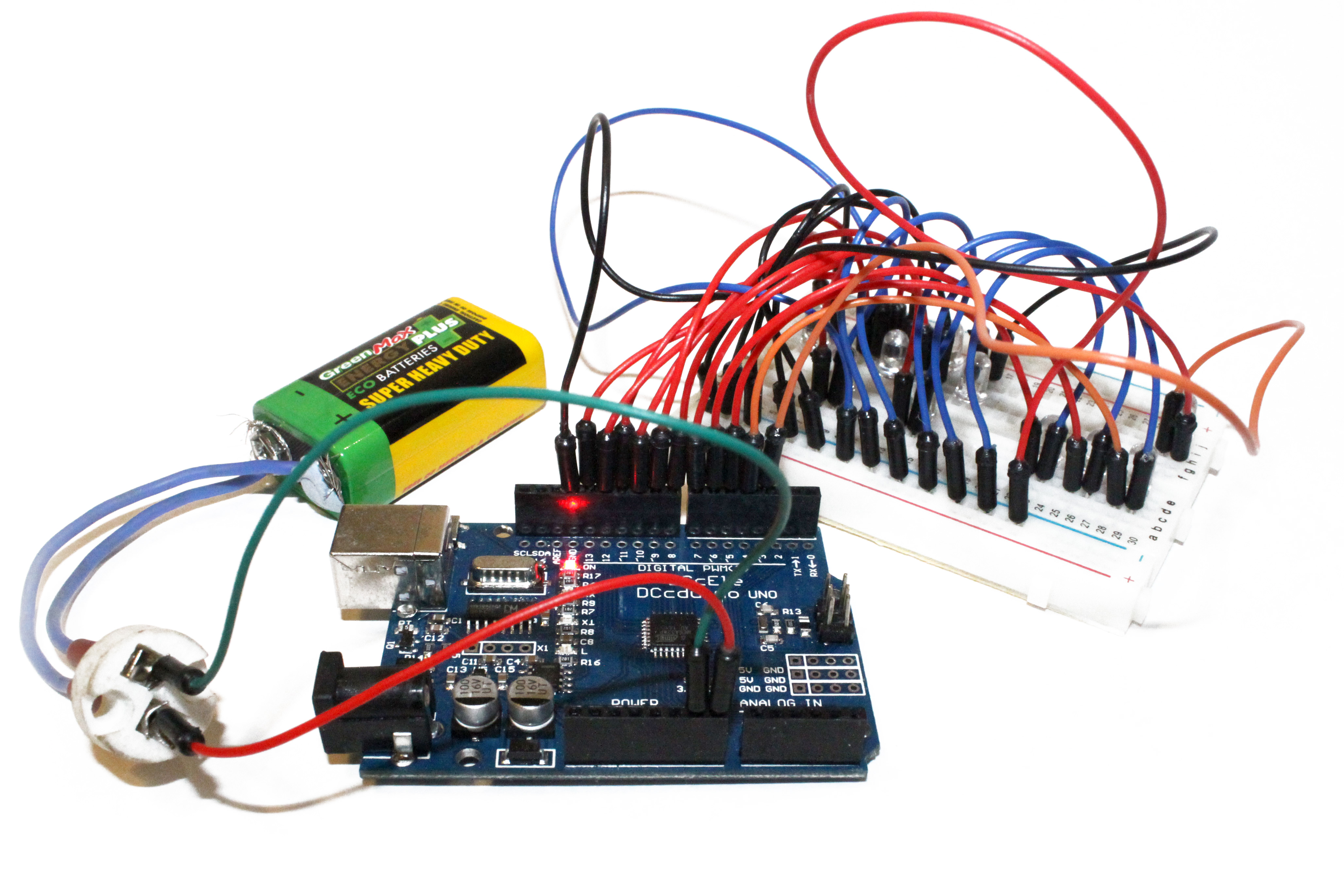
- insert 11 LEDs into the breadboard
- connect the LEDs anode/longer pins (+) with pin 3-13
- connect the cathode/shorter (-) pins to GND.
- open Arduino and open the attached code file. If you don't have the software, than download it here.
- disconnect the battery, connect the Arduino with your computer via USB cable provided.
- take a look at the code to see what it does. When you are testing you can set longer times so you can check if the LEDs are lit up correctly at a perceivable speed.
int delt=9; //delay time 9 ms - set this to 99
int blit=0.1; //delay time 0.1 ms - set this to 1 - upload the code to Arduino and see the result
Downloads
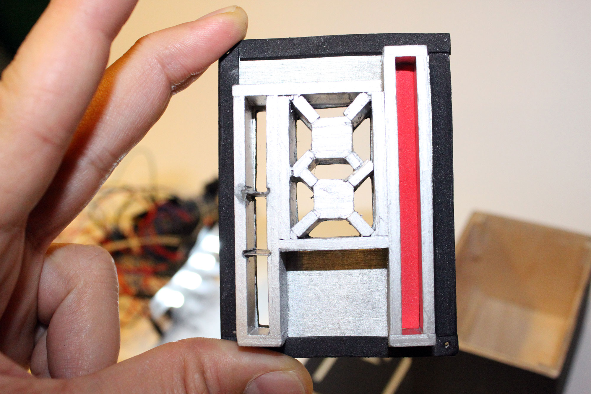
Making the Box
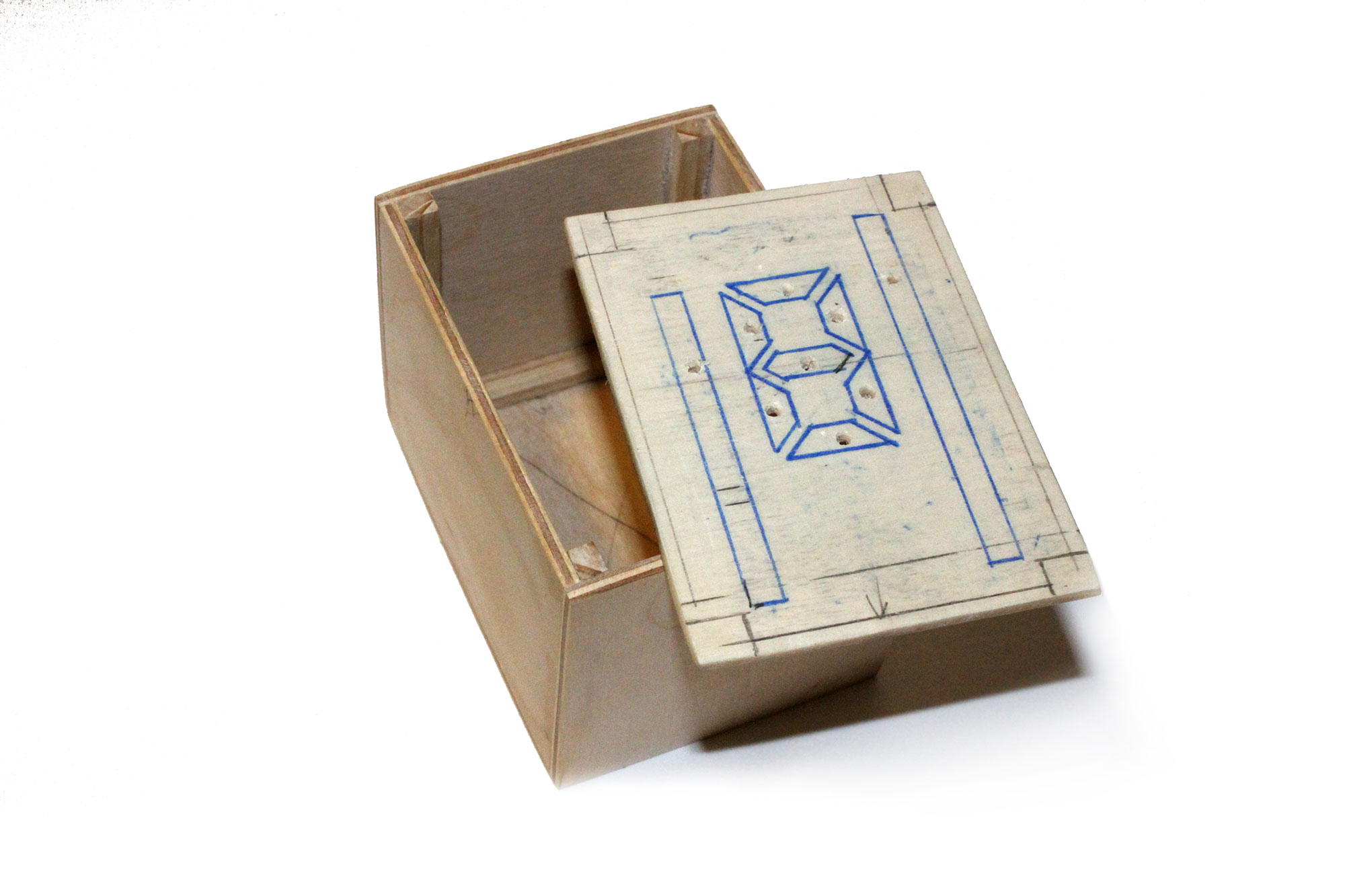
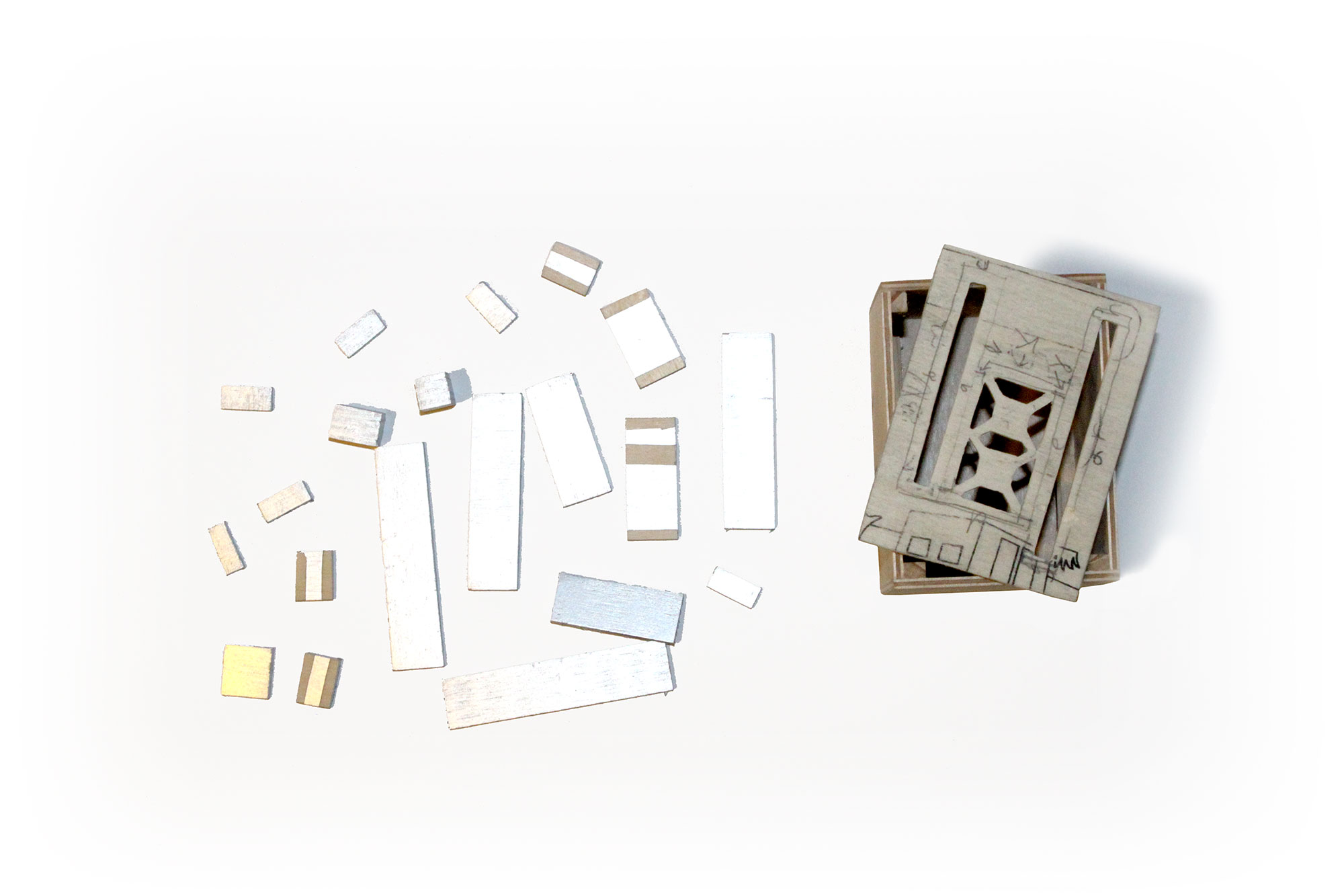
Build a box from plywood. The assembled box size is 62*85*77 mm (2.44*3.34*3.03 inch)
- print the attached PDF file
- copy with the help of a carbon paper the red outline on the plywood lid.
-
copy with the help of a carbon paper the blue outline on the black cardboard and cut out the shapes carefully. Stick tracing paper on the back of the cardboard - this will diffuse the light. These blue lines are inset 1 mm, because it is hard to make precise holes in the plywood.
- Cut 15 mm (0.59 inch) wide plywood strips than glue strips around the holes. You can paint reflective silver later or stick mirror sheets - this process helps bounce more light out through the holes.
Downloads
Solder, Mount
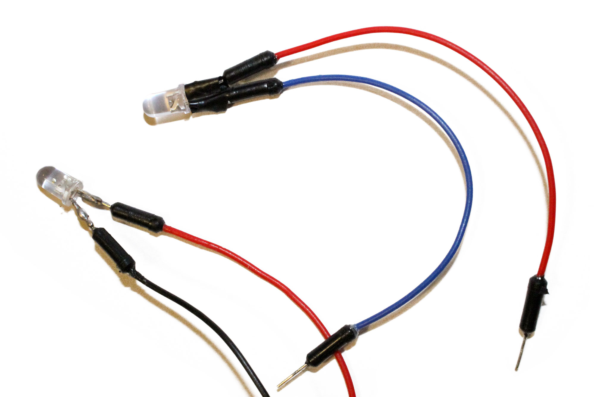
- Solder the wires to the LEDs, than insulate
- Test LEDs by mounting all of them in the right hole. If right, than fix them with hot glue.
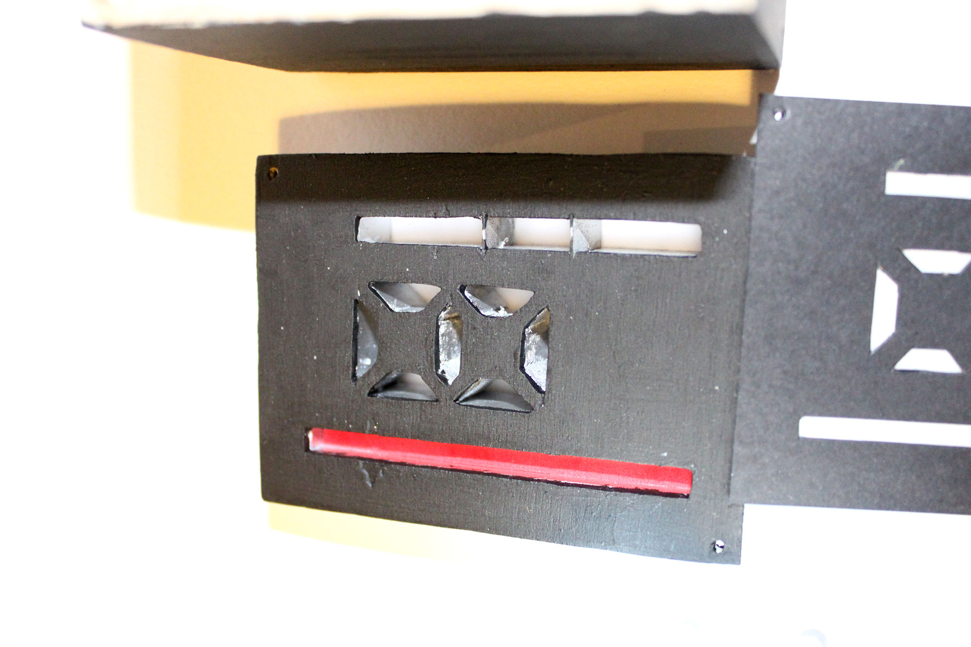
- glue some black hobby foam strips on the back of the lid, so when you close no light could escape on the edges.
- mount a colored piece of plastic sheet inside the longest slit.
On-Off
Make a hole, where the Arduino has it's power socket, insert the plug, than mount the battery outside the box with a velcro. I used this this improvised ON-OFF system instead of buttons. to have smoother and faster start. When i push the cable to the plus end, than the animation starts automatically.
Set your camera to a few seconds long exposure with self timer, than paint some light in a dark space. Adjust ISO and aperture until you got the desired quality. Additionally if you want the painter to be visible in the picture you can give him/her a radio trigger, which is triggering a flashlight.
Play, Measure, Enjoy
Thanks for Midlands Makerspace Athlone for the helping me with Arduino.