Interface the Rfid Module With Arduino
by suman_1790 in Circuits > Arduino
2762 Views, 7 Favorites, 0 Comments
Interface the Rfid Module With Arduino
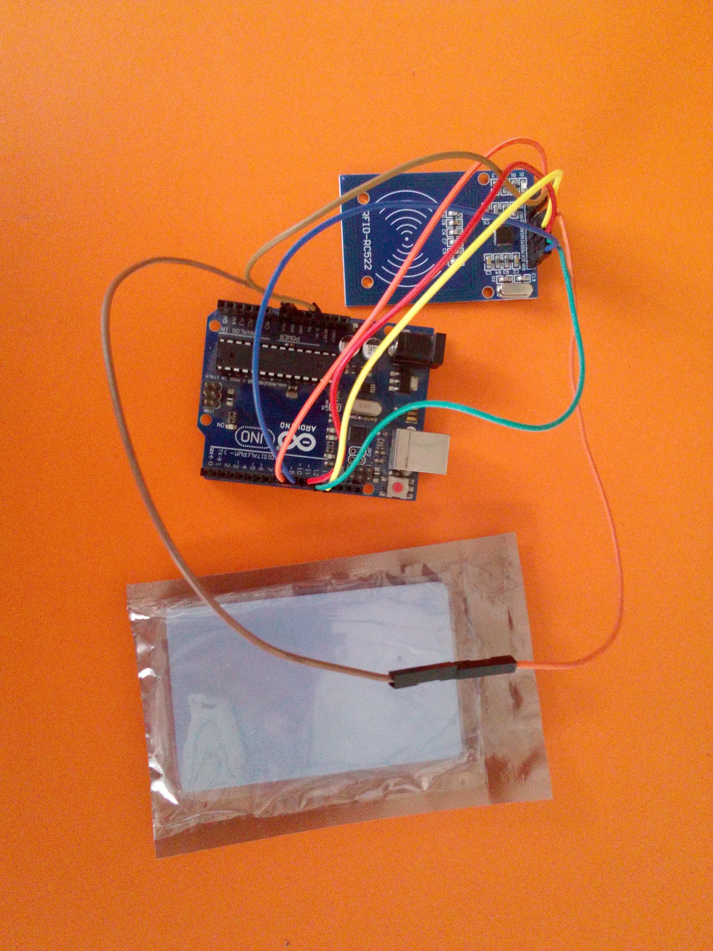
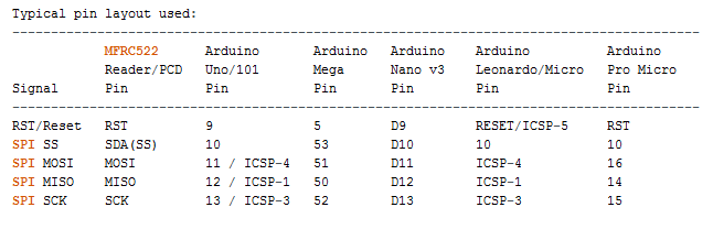
Do the connection by following the pinout connections mentioned in the above picture.
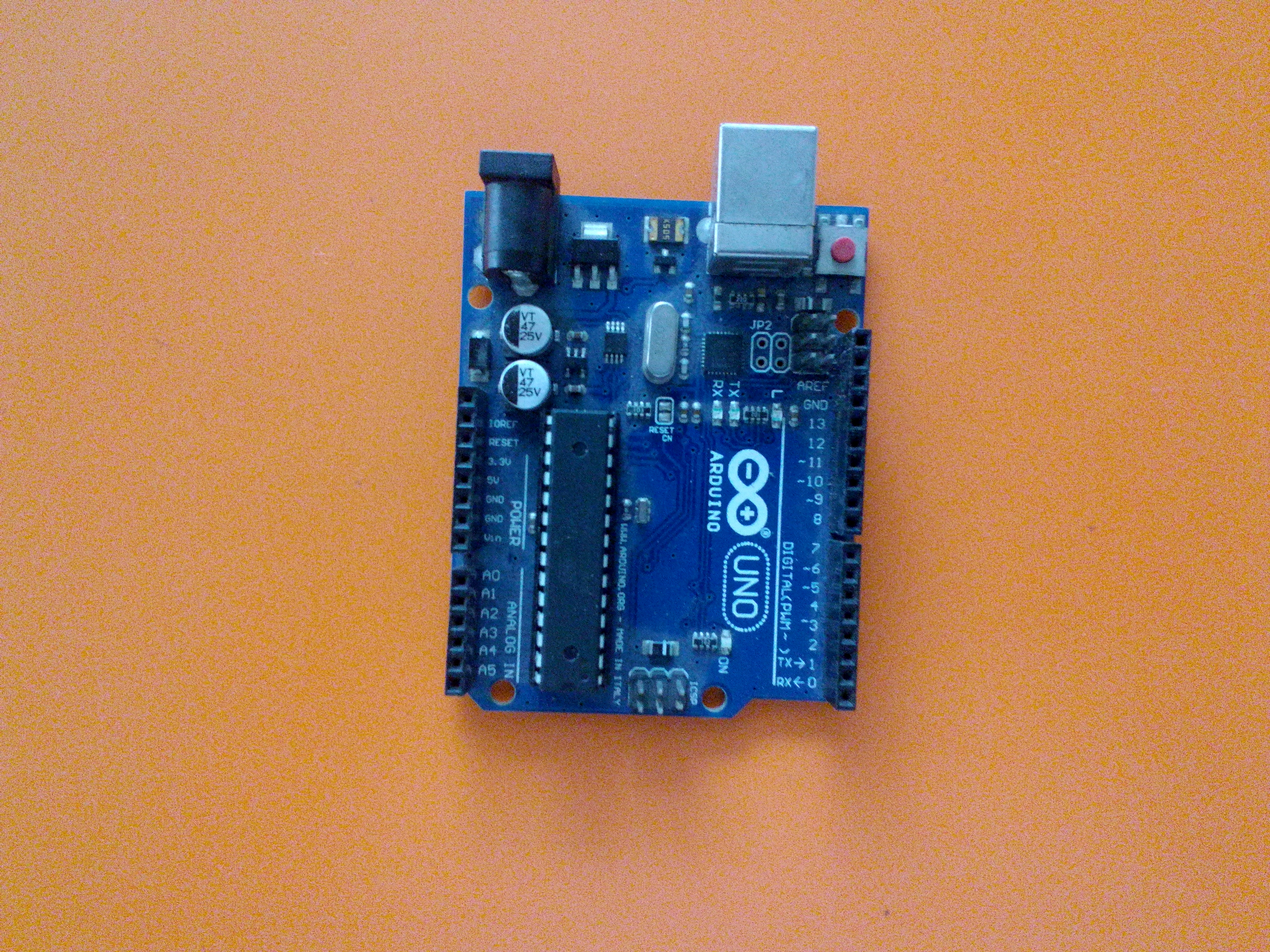
Here I used an Arduino UNO board along with RFID module.
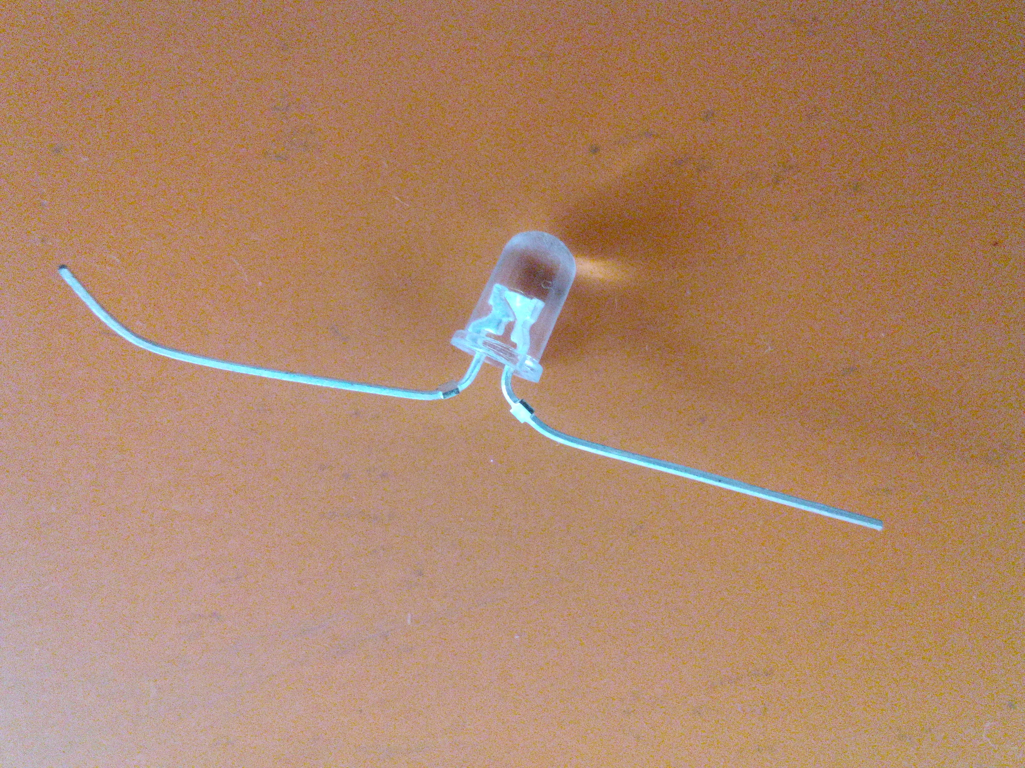
Connect LED for Indication Purpose
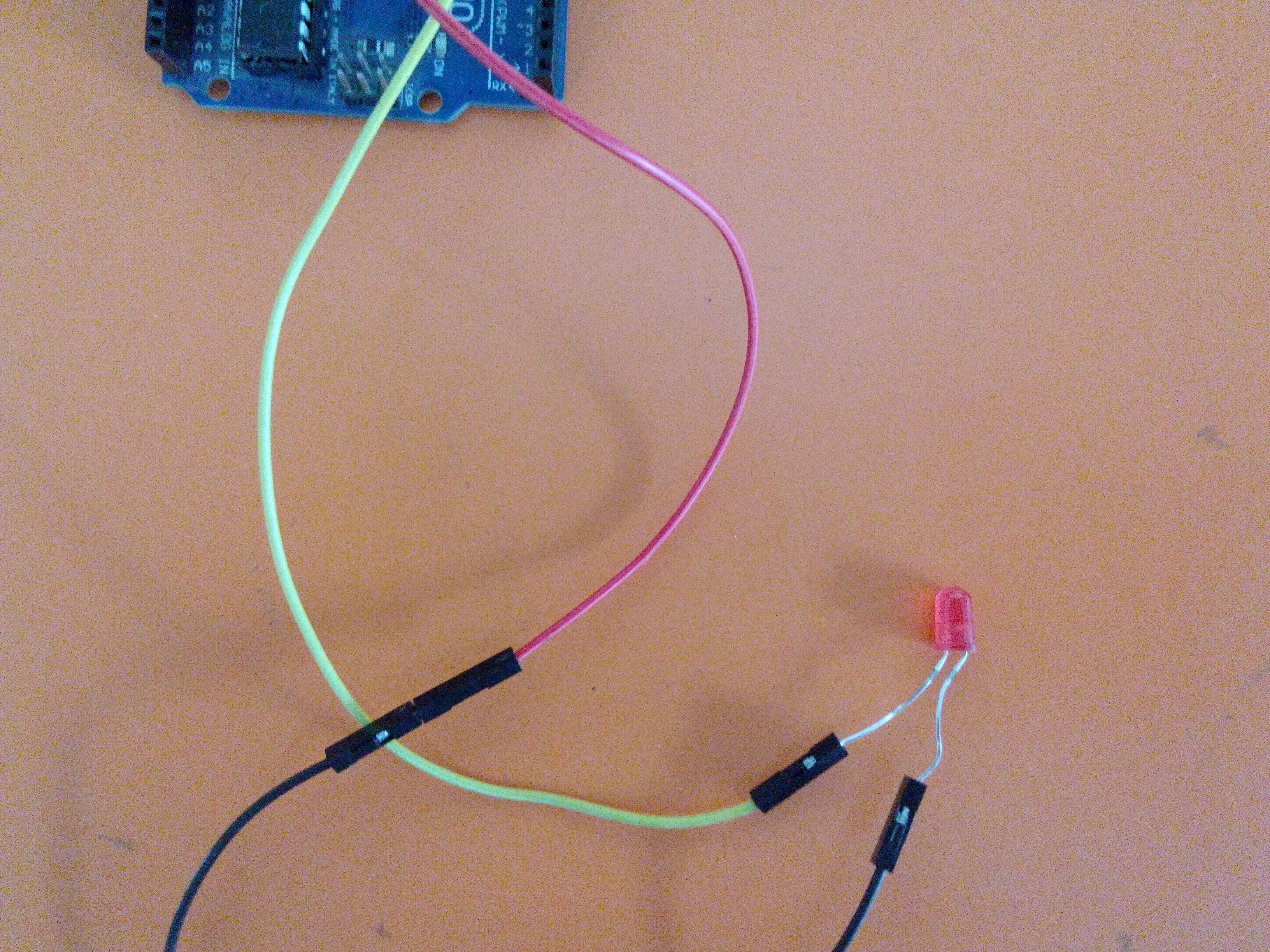
I'm using a visual indication i.e. LED.
Here I connected a red LED at digital pin 8 of Arduino UNO. The long pin of LED is +ve ,which is connected to digital pin 8 of Arduino UNO, and the - ve terminal will be connect to GND of Arduino UNO.
Time Measure Using Rfid RC522
Many times you may want to record the 'ON' & 'OFF' time of machine or any equipment.
Here, we are using RFID to control access to the machine/system as well record the operation time.
Basically RFID used for turn on a system using it's UID code identification. RFID tags and keychains are used for punching the rfid reader.
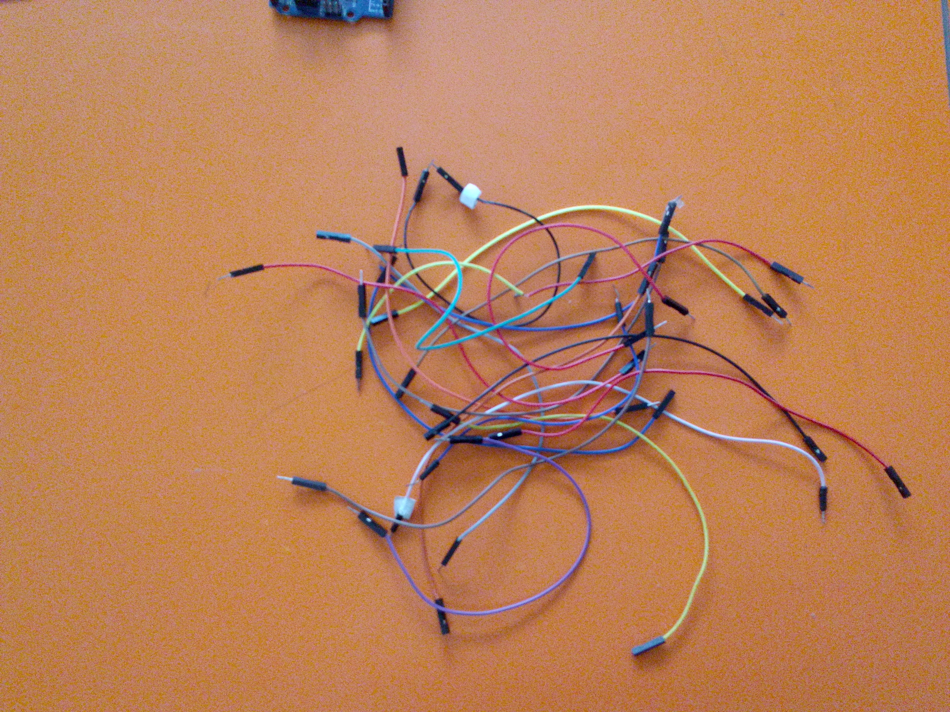
What we need:
- RC522 module
- Jumper wire
- Led(for indication)
- Arduino UNO
- Relay(5 volt)
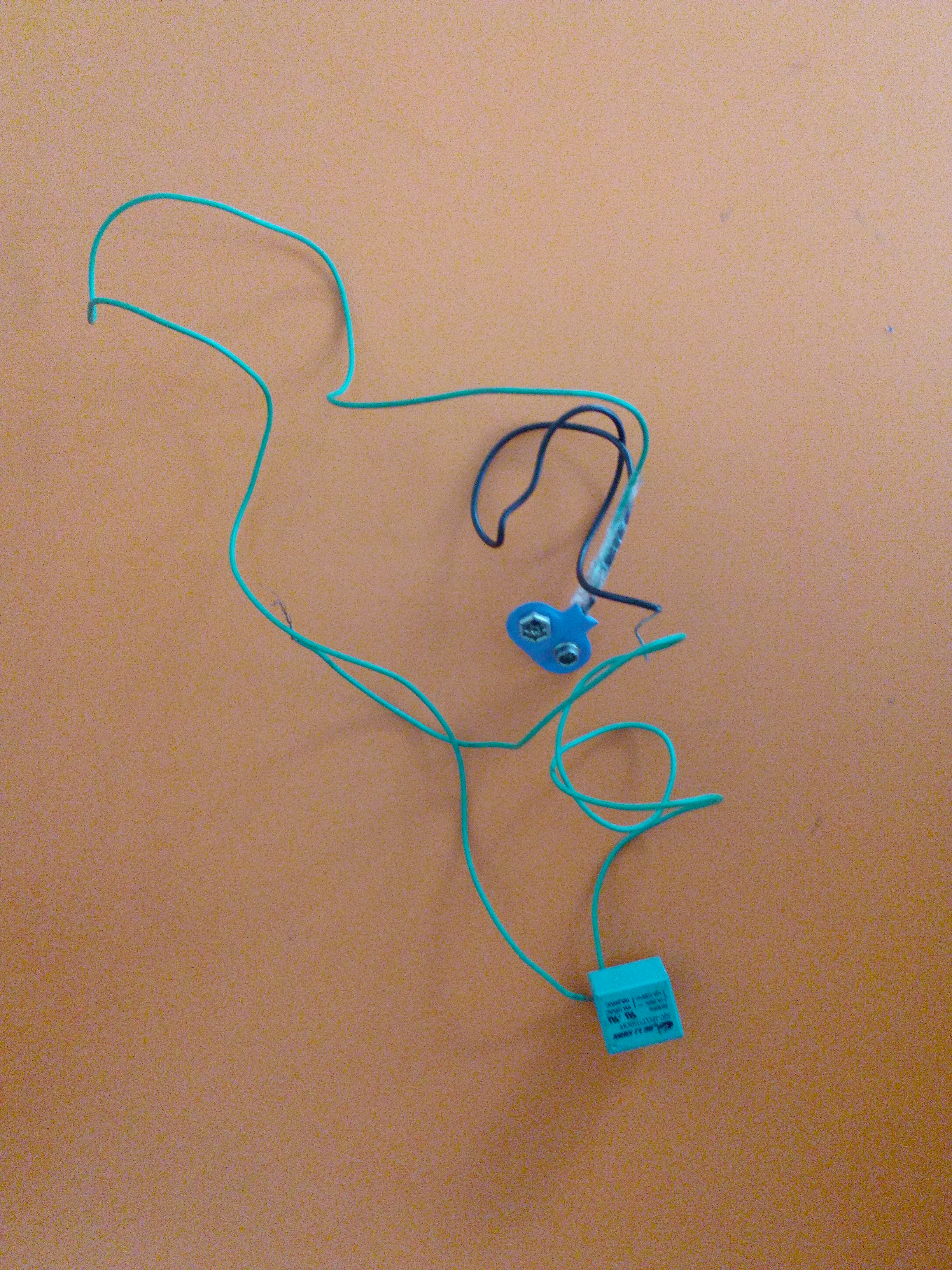
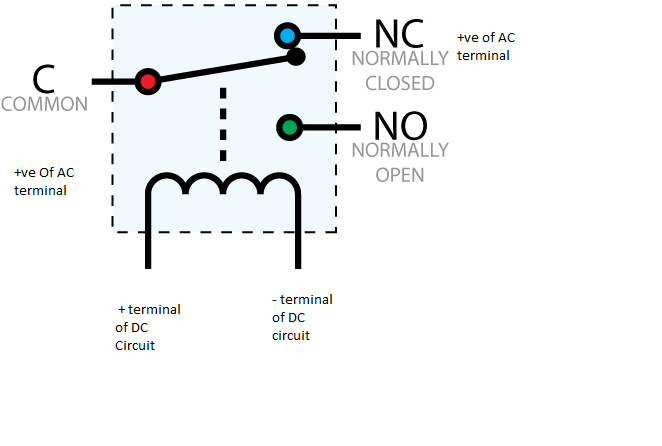
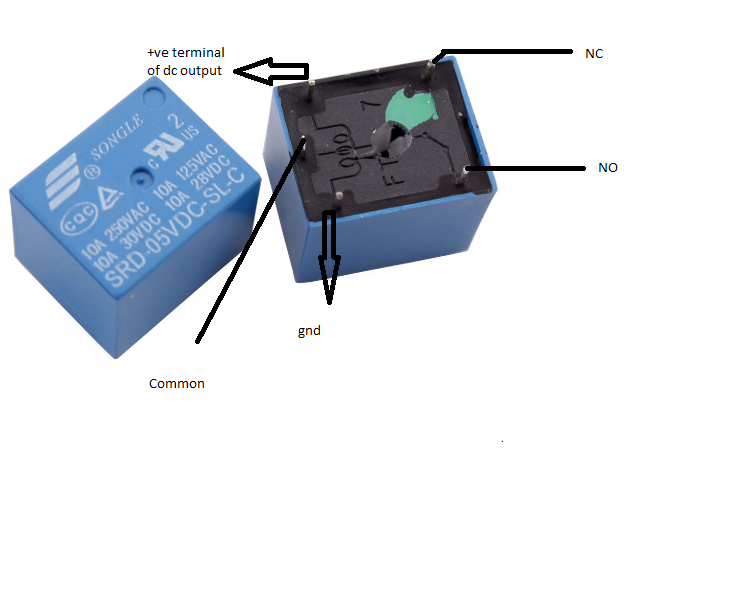
Connect the Relay
![IMG_20170830_170125[1].jpg](/proxy/?url=https://content.instructables.com/F0I/M89D/J6WGMB2B/F0IM89DJ6WGMB2B.jpg&filename=IMG_20170830_170125[1].jpg)
I've connect a relay for switching purpose. The " +ve terminal of DC output/ circuit " pin connect to relay connect to 5 volt of arduino UNO & "-ve terminal of DC output/ circuit" pin of the relay connect to the digital pin 4 of UNO.
COMMON and NC will link the main supply + ve terminal of supply voltage
and the supply -ve terminal will directly connect to the gnd of supply voltage.
Connect transistor emitter pin to arduino digital pin 4.
Upload the Code
Here in this code I attach red LED +ve pin to 8 pin of Arduino UNO.
Here I'm giving 5 volt supply of relay from Arduino UNO., and connecting the relay's " relay's -ve terminal from DC supply" pin I'm connect to 4 pin of Arduino UNO.
When the digital output come from pin number 4 is 'LOW', the power supply will go to relay ; otherwise not.
Now attach this controller with your system/machine which you want to provide restricted access.
Downloads
Let's Check
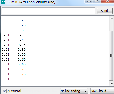
You can check the time from serial moniter.
Here the 1st line denotes Hour and 2nd line is denoting the munite.