TicTacToe Hardware Implementation Using RaspberryPi
by kafzal in Circuits > Raspberry Pi
2283 Views, 1 Favorites, 0 Comments
TicTacToe Hardware Implementation Using RaspberryPi
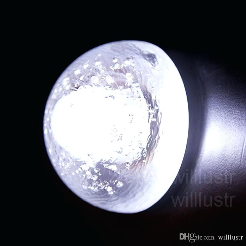
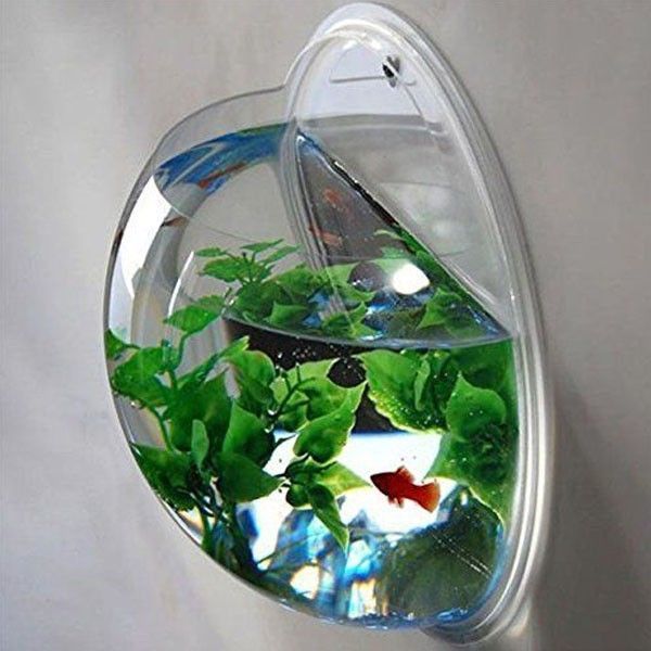
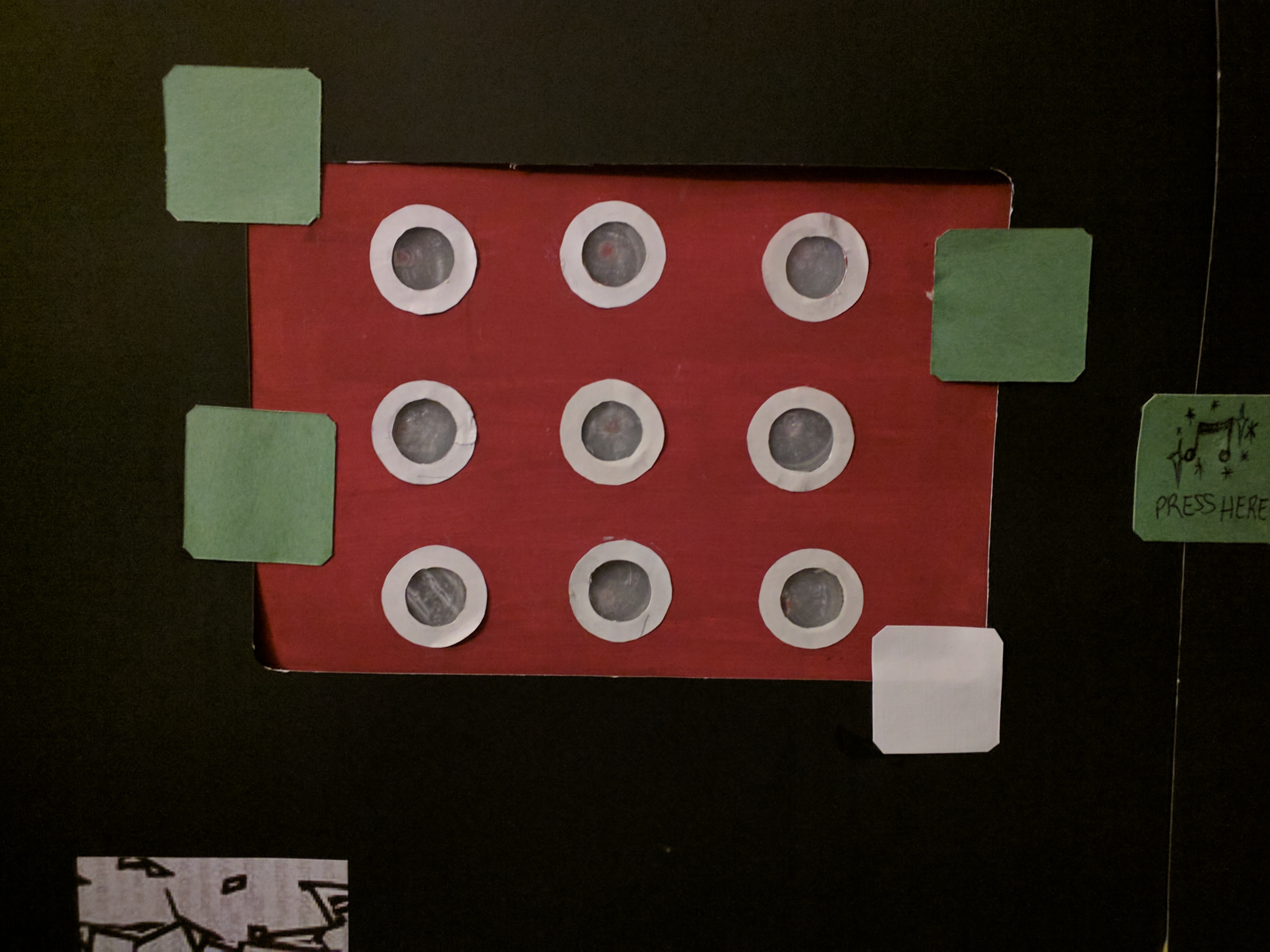
This project aims at building an interactive TicTacToe model using two different colored LEDs denoting the two players using a raspberry pi. The idea here was to implement this on a bigger scale in an alleyway - imagine a grid of 3x3 semi-globes (like ones shown above) stuck on the wall where pressing one initiates the game (and a specific colored LED turns on). This can be implemented in alleyways beside bars, pubs or any place where people have to line up and wait - hence making the zone an interactive area where people actually enjoy while they wait.
Supplies
For the model - I used the items available to me:
- Raspberry Pi 3 Model B+ with raspbian installed on the SD card
- Momentary Push Buttons - 9x
- LEDs - 9x Green, 9x Red
- Breadboard
- Wires - Female to Female, regular copper wires that usually come with dev kits -- 22 guage insulated copper wire (like this one (no affiliation with seller)- (https://www.amazon.com/Elenco-Hook-Up-Colors-dispenser-WK-106/dp/B008L3QJAS/ref=sr_1_1?keywords=copper+wires+elenco&qid=1568868843&s=gateway&sr=8-1)
- 220 ohm resistors - 9x
Setup the Breadboard With 18 LEDs
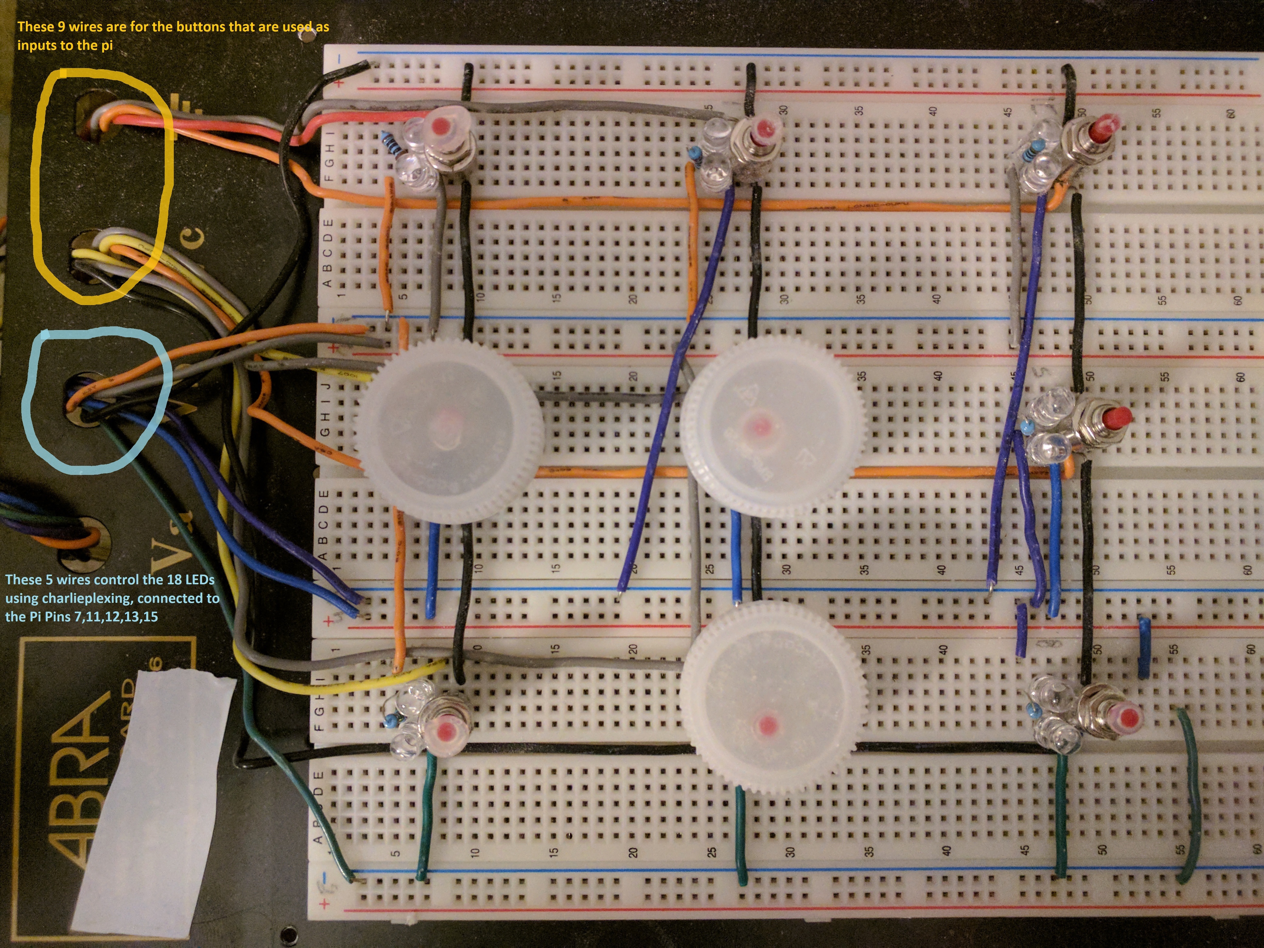
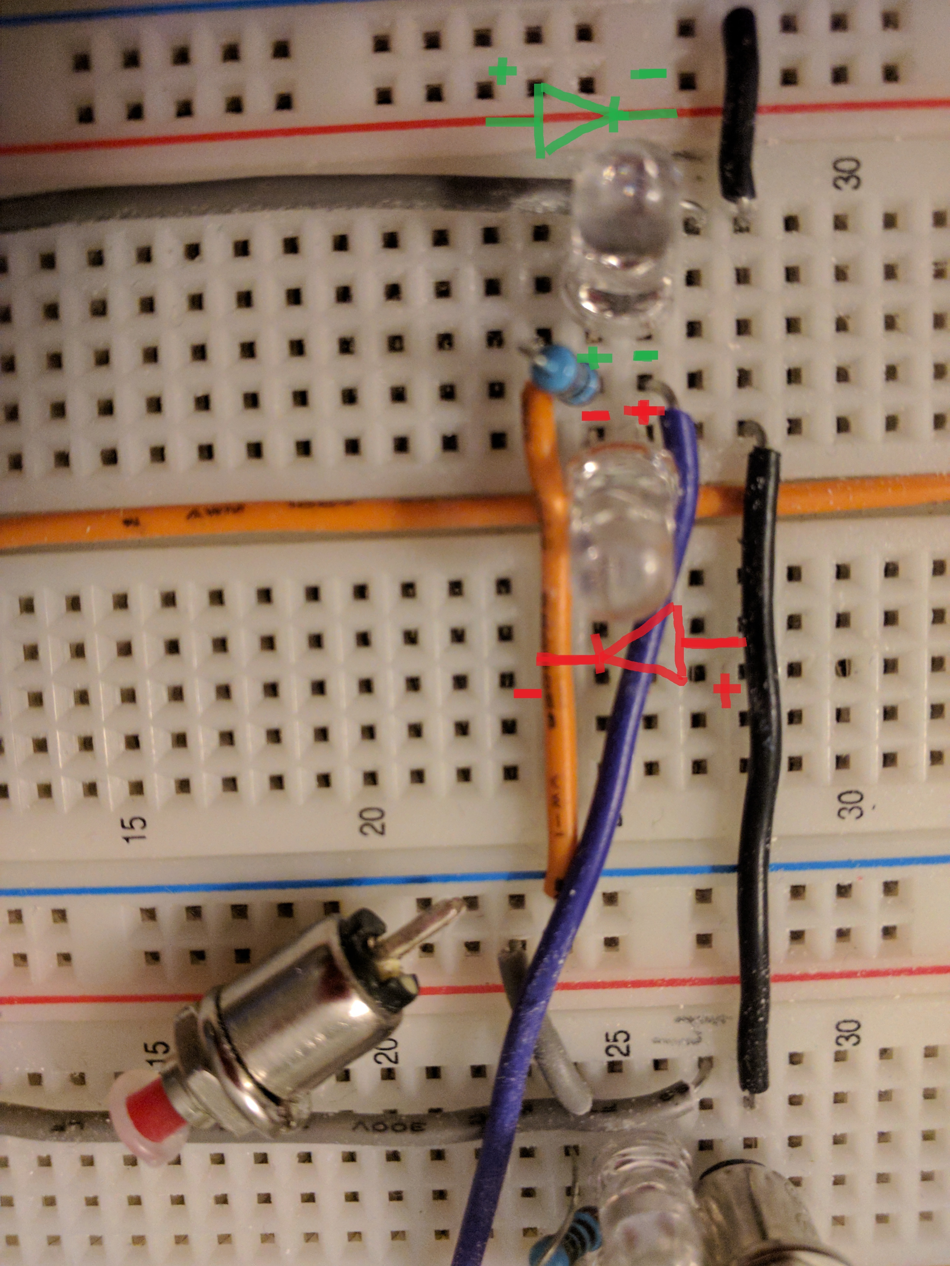
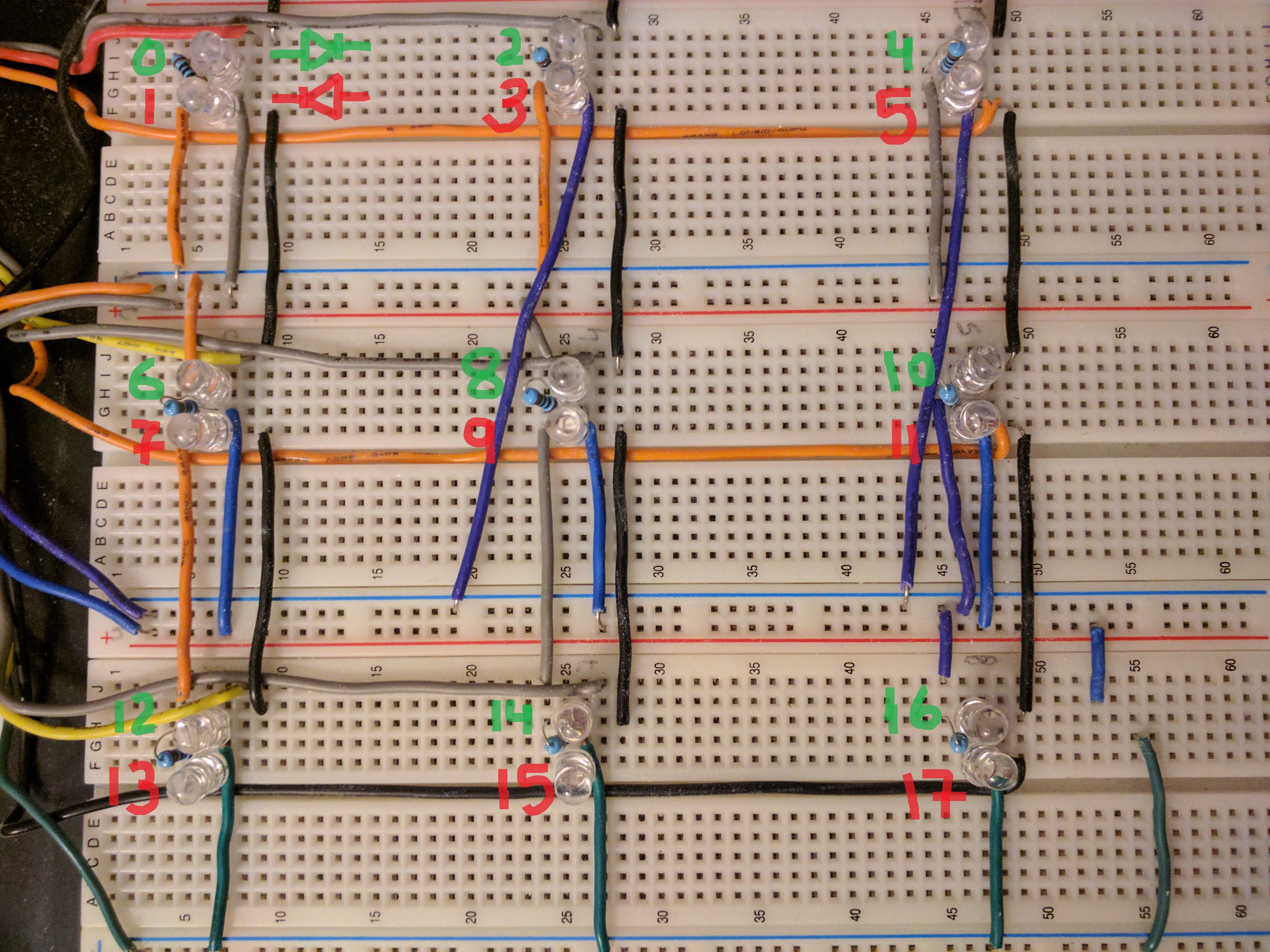
First, setup the breadboard in a grid of 3x3 with two different LEDs beside each other as shown in the picture above. We will drive 18 LEDs using only 5 pins (referred as control pins below) from the raspberry pi. This is done using charlieplexing which is explained beautifully in this instructable (https://www.instructables.com/id/Charlieplexing-wi...). Observe I am using bottle caps as show in the pics above to cover up my buttons here to fit the model.
1. First place the LED pairs (and their corresponding resistors) ONLY (one red other green or whatever colors you choose) in opposite polarity across the same rows in the breadboard (see pic above with zoomed in view of 1 pair). MAKE SURE you keep the same sequence, i.e. the top one is green and the bottom one is red for ALL LED pairs.
2. Then wire the LEDs (NOTE: each control wire goes to the LED pair via the 220 ohm resistor) using the instructable above - its very detailed with excellent wiring instructions, just remember you're forming a grid with LEDs 0 and 1 at the top left and LEDs 16 and 17 in the bottom right. (Numbering the LEDs helps with the physical setup and programming later on). OR follow along the wires in the 2nd pic to see how I wired the LEDs -- observe the following colored wires flowing from the top row to the bottom rows:
- Black Wire (Pin 6 ground from pi) at the very top goes to the entire rail -- I feed this wire down for each of the 9 buttons
- Orange Wire (Pin 7 - control pin1 from pi) in the 2nd rail above LED 3 goes to the entire rail again (-ive rail)
- Grey Wire (Pin 11 - control pin2 from pi) in the 2nd rail above LED 3 goes to the entire rail as well (+ive rail)
- Purple Wire (Pin 12 - control pin3 from pi) in the 3rd rail above LED 6 goes to the entire rail (-ive rail)
- Blue Wire (Pin 13 - control pin4 from pi) in the 3rd rail above LED 6 goes to the entire rail (+ive rail)
- Green Wire (Pin 15 - control pin5 from pi) in the 4th rail below LED 6 goes the the entire rail (-ive rail)
The wires are color coded so should be able to follow along - please make sure the polarity of the LEDs is set properly else it will not work!!
Add the 9 Buttons Beside the LEDs
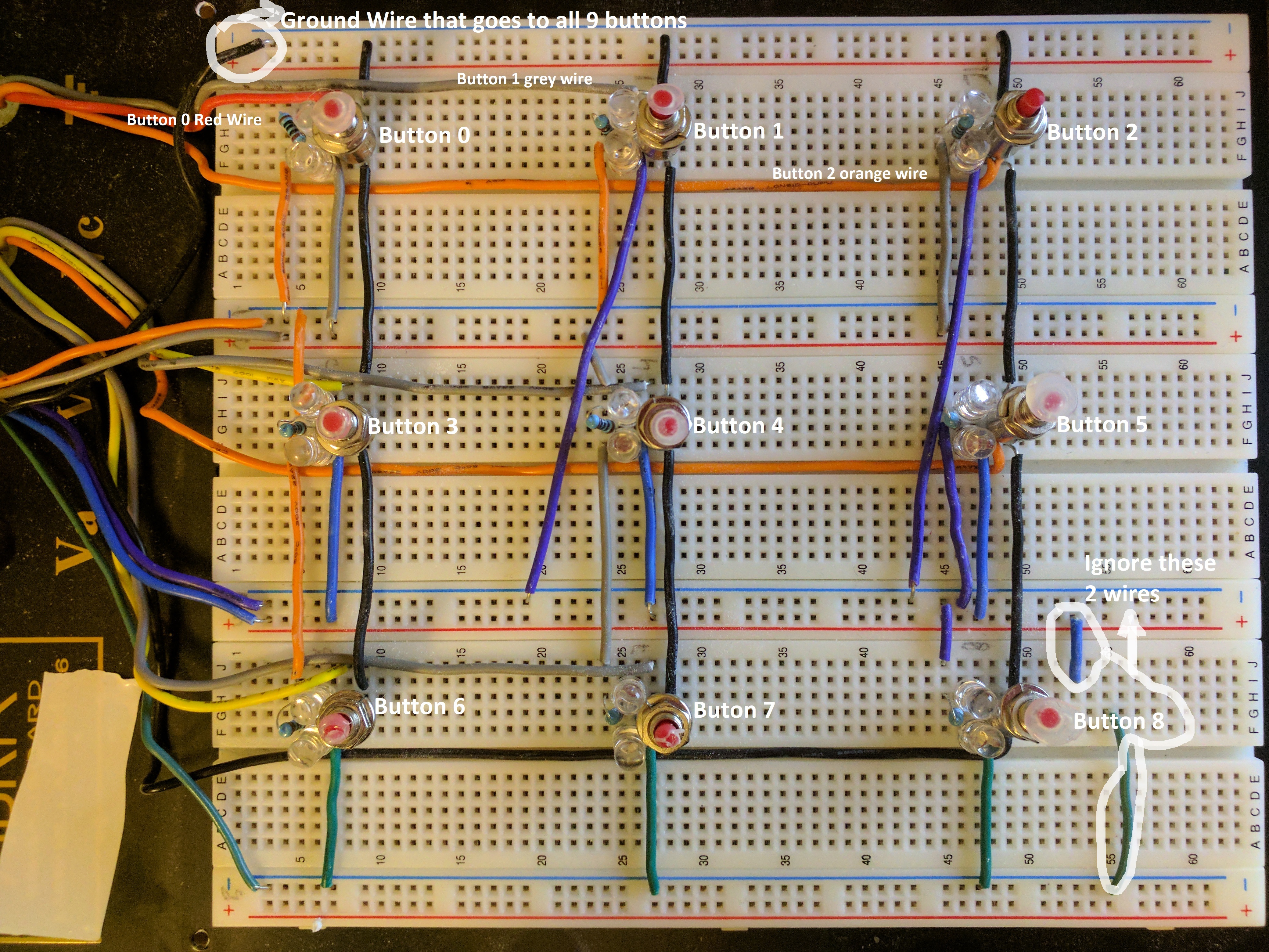
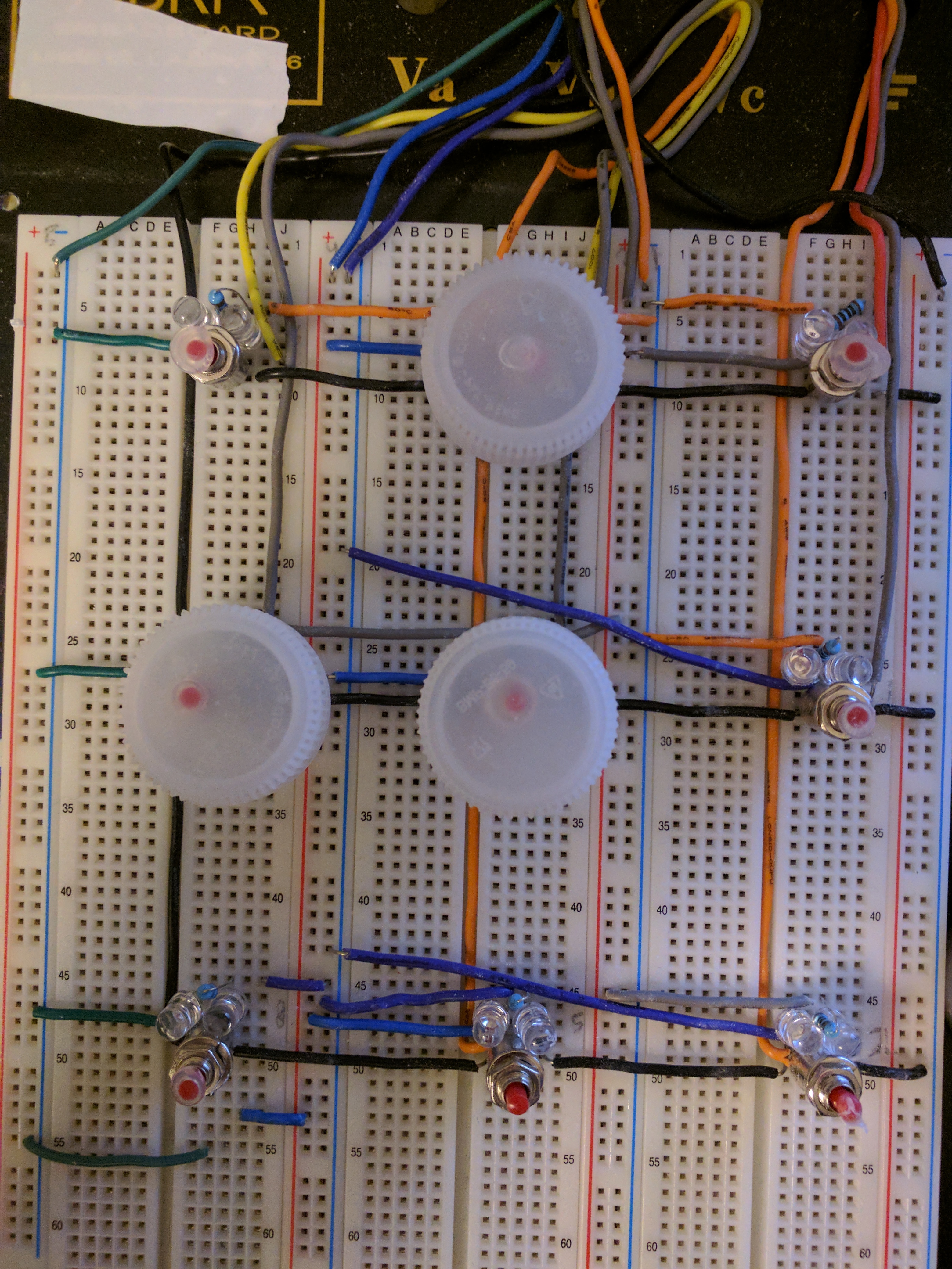
Beside each pair of LEDs, add the momentary push button with one leg inside the black ground wire row and the other into the row with wire coming from the raspberry pi. NOTE - It is best to embed the wires even before putting the buttons in as shown in the picture in step 1 without any buttons. It would be best to first setup the ground wires for all 9 buttons and then setup the 9 wires going to/coming from the pi (don't worry about what pin the wires are coming from since you most likely have not hooked up these wires to the pi yet - thus just neatly add 9 wires for the 9 buttons that take user input to the pi) as shown in the pictures above.
Connect the Wires From the Breadboard to the Pi
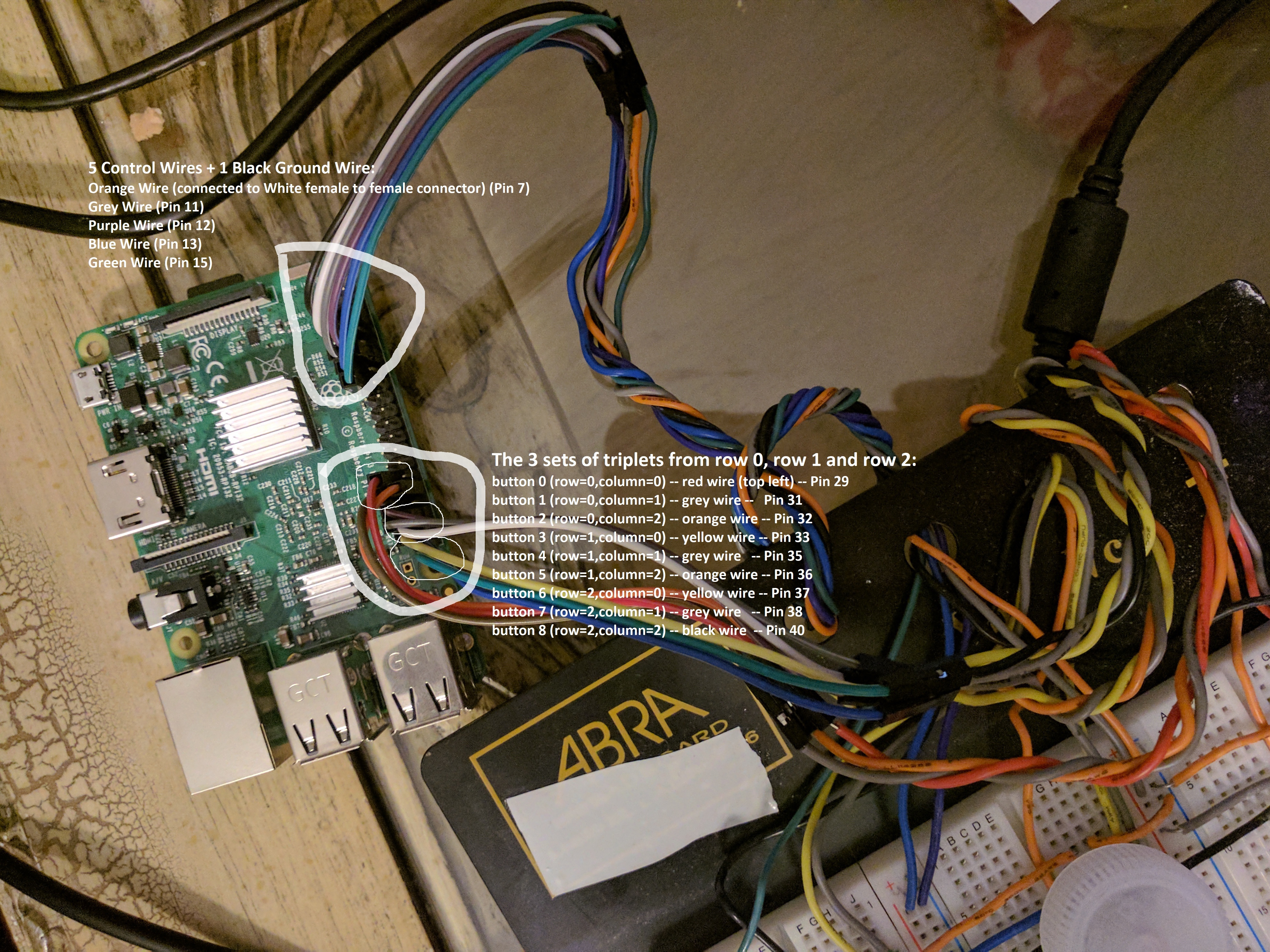
In the last 2 steps we hooked up the breadboard with LEDs and buttons and their corresponding wires. Now we connect these wires to the pi.
As already outlined in step 1 - we connect the 5 control wires and the black ground wire for the LEDs to pins as such:
- Black Wire (Ground wire) (Pin 6)
- Orange Wire (Pin 7)
- Grey Wire (Pin 11)
- Purple Wire (Pin 12)
- Blue Wire (Pin 13)
- Green Wire (Pin 15)
Now we connect the 9 wires coming from the 9 buttons to the pi. It is best to make twisted triplets of the 3 buttons in a row for easier management as such:
- button 0 (row=0,column=0) -- red wire (top left) -- Pin 29
- button 1 (row=0,column=1) -- grey wire -- Pin 31
- button 2 (row=0,column=2) -- orange wire -- Pin 32
- button 3 (row=1,column=0) -- yellow wire -- Pin 33
- button 4 (row=1,column=1) -- grey wire -- Pin 35
- button 5 (row=1,column=2) -- orange wire -- Pin 36
- button 6 (row=2,column=0) -- yellow wire -- Pin 37
- button 7 (row=2,column=1) -- grey wire -- Pin 38
- button 8 (row=2,column=2) -- black wire -- Pin 40
Once all connections are made we are ready to upload the code!!
Upload the Code!
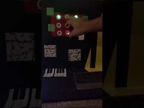
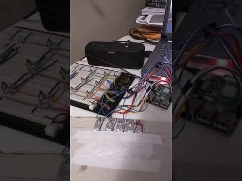
Once all connections are made, we are ready to upload the code. Assuming you are connected to the pi via rdp OR VNC - please save the following files on the pi (inside same folder) and run the FinalVersion.py file either via terminal OR via thonny. Also ensure you have your speakers connected to the pi (bluetooth speakers will do as well).
If you get stuck at any point please let me know and I will do my best to help you out!!
PS: This was my first ever instructable, so let me know how I did!! :O