Threads in 123D Design
by sideeffect001 in Workshop > 3D Printing
6871 Views, 35 Favorites, 0 Comments
Threads in 123D Design
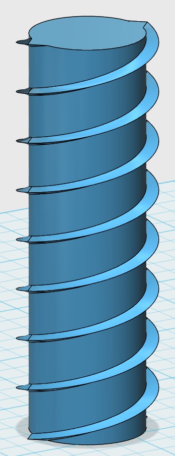
I do a lot of my drawing in Autodesk 123D Design. Mostly because it's free, partly because it's simple to use. One problem I've noticed is drawing threads for nuts, bolts, screws, etc. is not easy. So here is the method that I have found works best for me.
Draw Your Base Shape
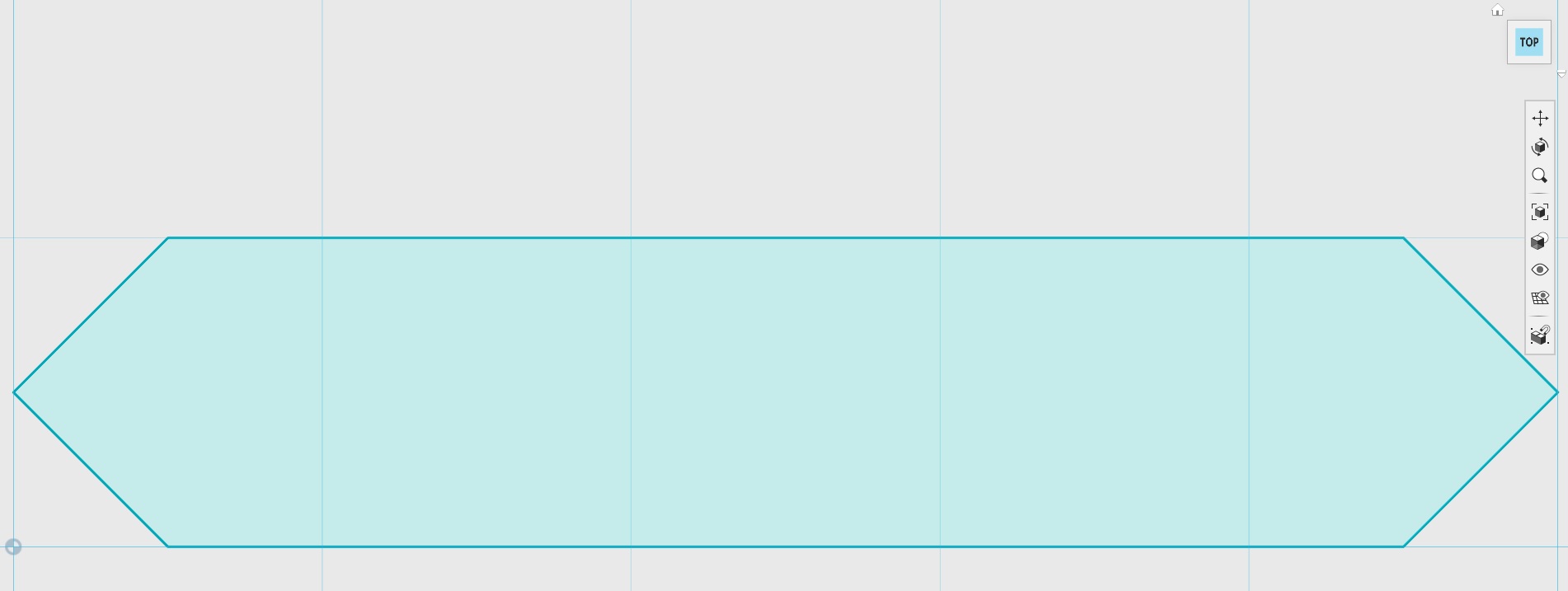

The size and shape of your threads will be determined by the base shape you start with. The first image is the shape I use most often which yields a simple thread with a triangular cross section.
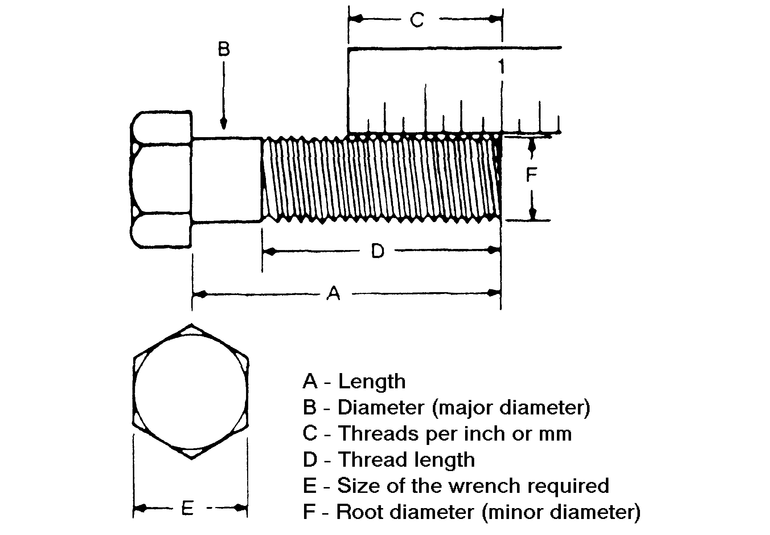
The size of your bolt and threads will be determined by the lengths you give to A and B in the second image. Distance A will become the major diameter of your bolt. Distance B will be the minor Diameter. These are B and F respectively in the example image I've included 3rd.
Start Building Your Bolt


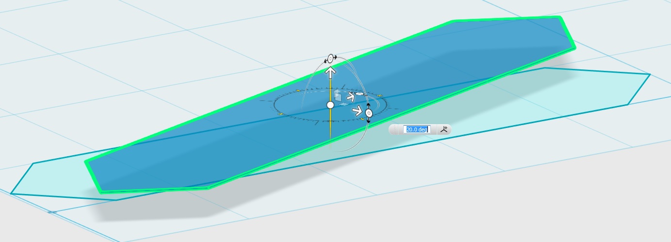
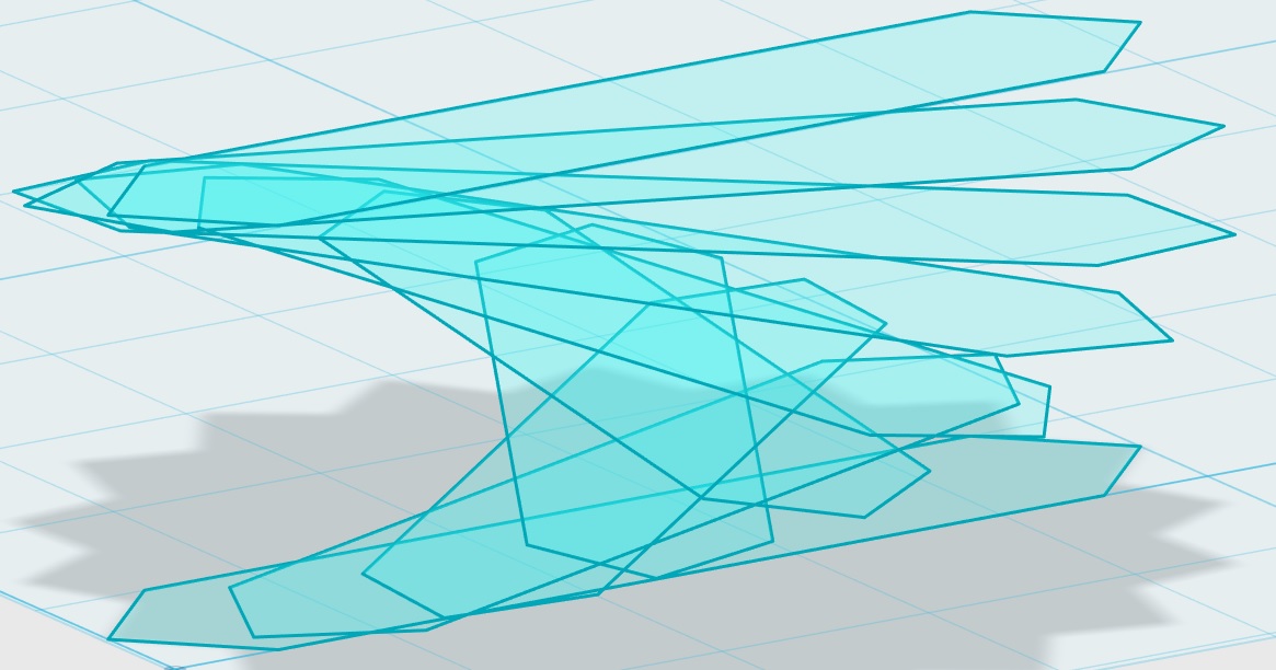
Next you're going to move the shape into place. Start by moving it up the Z axis. (Image 2) The distance that you raise the shape should be 1/9th of your pitch. I went with 1mm so my pitch will end up being 9mm, not terribly practical but it gives you the idea. The reason you raise 1/9th is that there will be 9 steps in this half revolution of your threads.
Rotate the shape you've raised 20 degrees. (Image 3)
Repeat these steps 8 more times. Each time copy/pasting the highest shape, raising it up, and rotating it. Be sure to raise and rotate the same amount each step or your threads will come out wonky.
When all this is done your top and bottom shapes will line up when views from above.
Loft
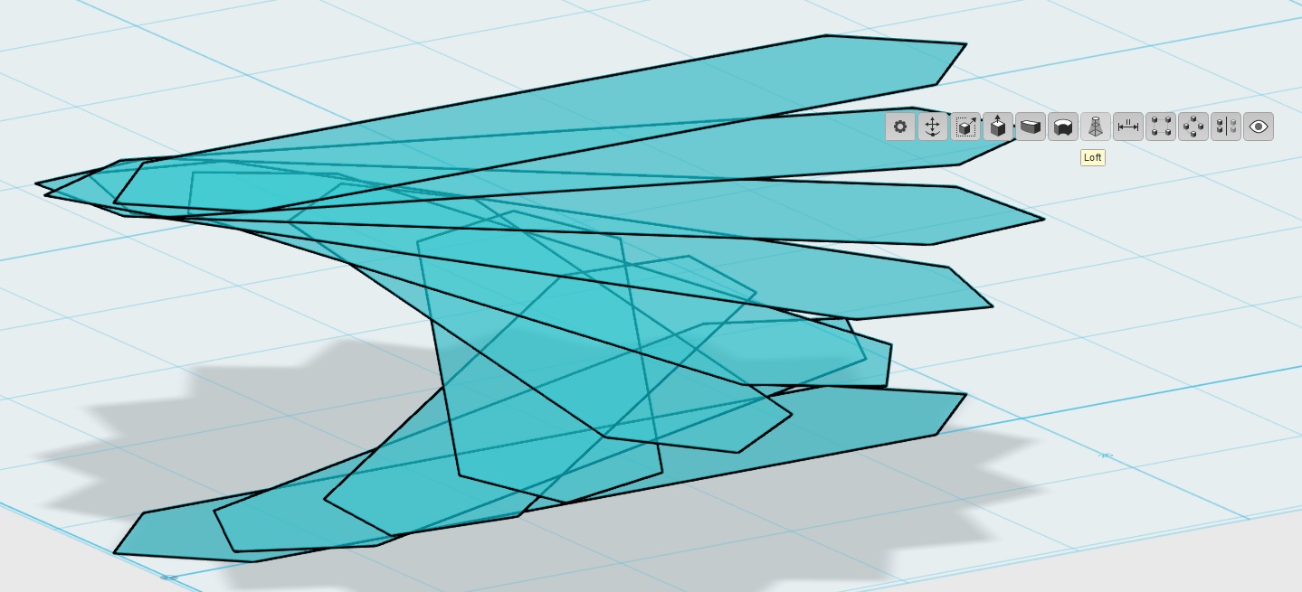
Select all the shapes you've created. Be sure to select them in order from bottom to top. (Image 1)
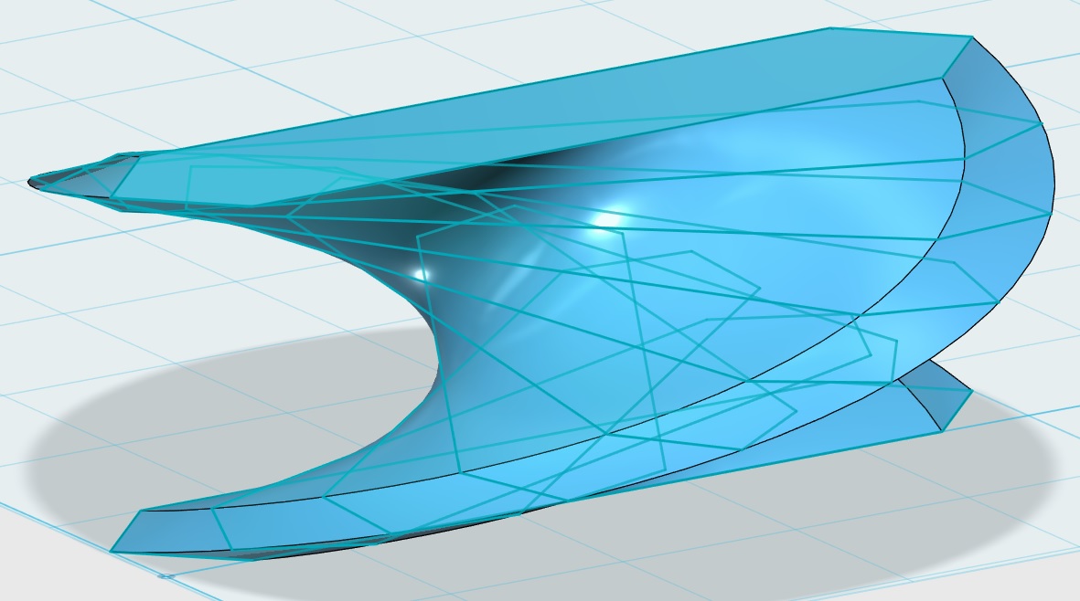
Now, loft them. (Image 2)
Draw Minor Diameter Cylinder
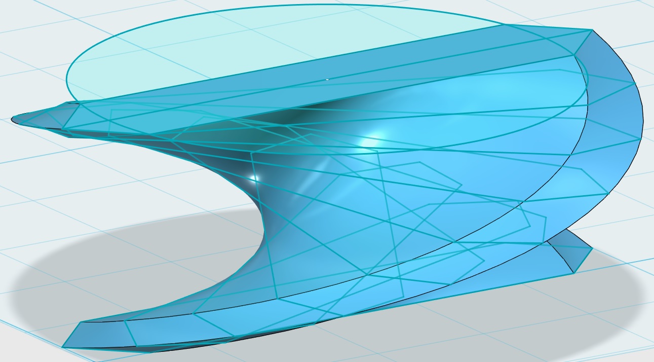
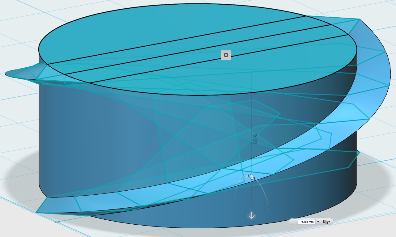
Now, select all the parts of this circle and extrude them, merging the resulting solids. Extrude the total length of you pitch. In this case that distance is 9mm.
Now you have one section of your bolt.
Build Your Bolt
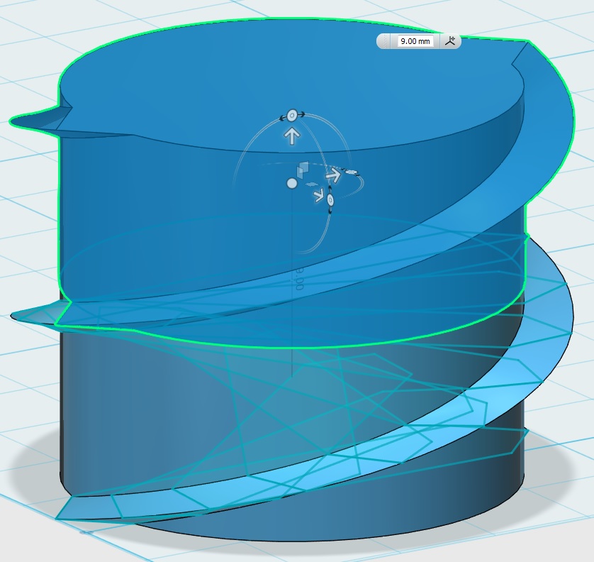

From here you can copy/paste the solid bolt section you have created and raise it up the Z axis to match up with the existing section. (Image 1) Repeat this step as necessary to give you the thread length required for your project. When you're done you can make all your sections into one object by selecting the Merge option. (Image 2)
And you're done. Hope this helps.
Thanks for reading.