DIY Particle Detector With a Thermoelectric Cloud Chamber (8 Steps W/ Pictures)
by thomas_wjc in Workshop > Science
663 Views, 6 Favorites, 0 Comments
DIY Particle Detector With a Thermoelectric Cloud Chamber (8 Steps W/ Pictures)
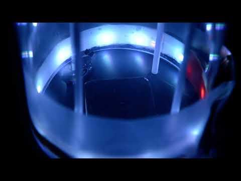


Hi, I'm Thomas Wang, an 11th grade physics student at Shady Side Academy. My friend Jefferson and I built this for our Physics II Calculus semester 1 project, and we look forward to seeing our thermoelectric cloud chamber be used as a demonstration tool for the inorganic chemistry class taught by Dr. Devon Renock in future semesters!
A Peltier-based thermoelectric cloud chamber is an intuitive and rewarding way to build a particle/radiation detector. The cloud chamber originated as a tool to visualize ionizing particles through liquid molecules. The condensed ‘cloud’ formed from the supersaturated vapor in the cloud chamber interacts with the ionizing particles (for example, ɑ particles, β particles, or gamma particles) making these rays visible from the naked eye. Through a cloud chamber, the properties and movements of radiation can be observed.
Supplies


The following materials are used:
- Peltier TEC2-19006 link
- AMD CPU heatsink cooler link
- Variable power supply (only need 12V for this project)
- BRK ionization smoke detector link
- 3D printed components
- 7" x 4" glass dome link
- LED strip
- Sponge
- 91% isopropyl alcohol link
- Alligator clips
- Wires (and a soldering kit)
- Thermal grease
The links are just for reference, to recreate our cloud chamber these components do not have to be exactly identical to ours! All of the materials used for this project could be found on Amazon, Home Depot, Lowe's, or Walmart (although we "borrowed" from our school lab...)
We took inspiration from this instructable by mosivers and simplified their idea without the voltage source and laser cut enclosure.
Background
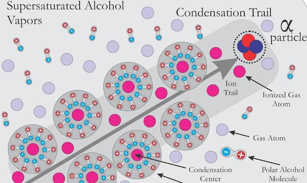

To ensure particle tracks would form, a supersaturated vapor must form in the cloud chamber. Supersaturated refers to a state where vapor density is higher than the equilibrium vapor density at a given temperature, thus making it unstable. Alcohol vapor is preferred for its lower freezing point (-89.5°C), and the temperature gradient in the chamber forms a mist. For a supersaturated alcohol vapor, the temperature necessary in the chamber was determined to be around -25°C. The vapor would not condense as it requires a nucleation site, which usually appears in the dust particles or a dirty surface. However, by isolating the cloud chamber, once the charged particles pass through the chamber (e.g., from a radiation source) they would collide with vapor molecules and ionize them, which in turn knocks off electrons and creates gas ions leaving an ion trail.
A thermoelectric cooling solution is preferred for our purposes over a traditional dry ice approach, as using dry ice would be rather inconvenient --- it would run out eventually and needs replacement frequently. To cool the alcohol vapor, a Peltier module is used. Peltier modules use lined-up P-type and N-type semiconductors to create a constant temperature difference; on one side heat is absorbed and on the other heat is radiated, creating one hot surface and one cold surface. The benefits of using Peltier are small device volume and stable temperature difference; however, peltier devices are extremely inefficient with power, and they cannot also dissipate heat by themselves, meaning that an extra heatsink is necessary for the cooling to last. We address this by using a CPU cooler.
Initial Stage Testing
Initially, we modeled after this youtube video by ElectroBOOM which uses several TEC1 peltier modules laid out flat. They simultaneously cooling one large surface using an aluminum heatsink immersed in water. Theoretically, the peltier modules should be able to hold a constant temperature difference on both sides, and water that is cold enough should have been enough to keep the cold side at a temperature low enough (< -25°C) for the formation of the supersaturated mist. However, we soon realized one layer of TEC1 peltiers could only cool the temperature of tap water from room temperature to around 15°C. The water also heated up fairly quickly, with the formation of some bubbles around the aluminum heatsink.
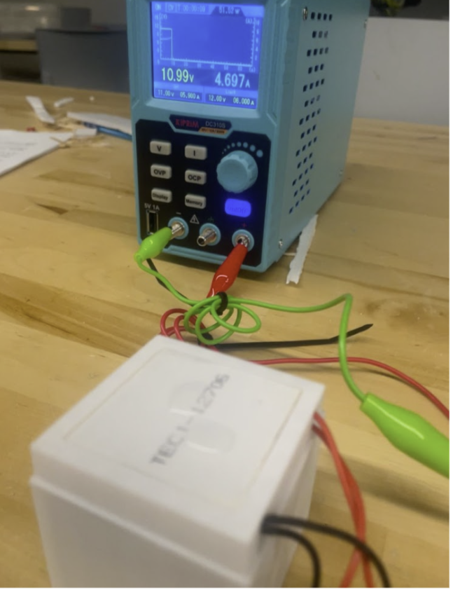
Cooling of the peltier modules seemed to be the main issue. We tried to address this by building a 3D-printed container with a water flow to circulate the water and cool the peltier more effectively (shown in image above). This yielded similar results to the aluminum heatsink. The module still warmed up quickly, and the problem with only the top layer heating also remained. This was likely due to the 3d prints not being watertight and there was no effective circulation of water.
Trying to increase the power of the peltier module, we stacked 2 peltiers on one 3D-printed rack. We did not use thermal grease, which could have made this design more efficient. The lowest recorded temperature for this was -19ºC, still not enough to the -25ºC required. In addition, we did not have an effective cooling solution for this design.
Peltier & Cooling Testing
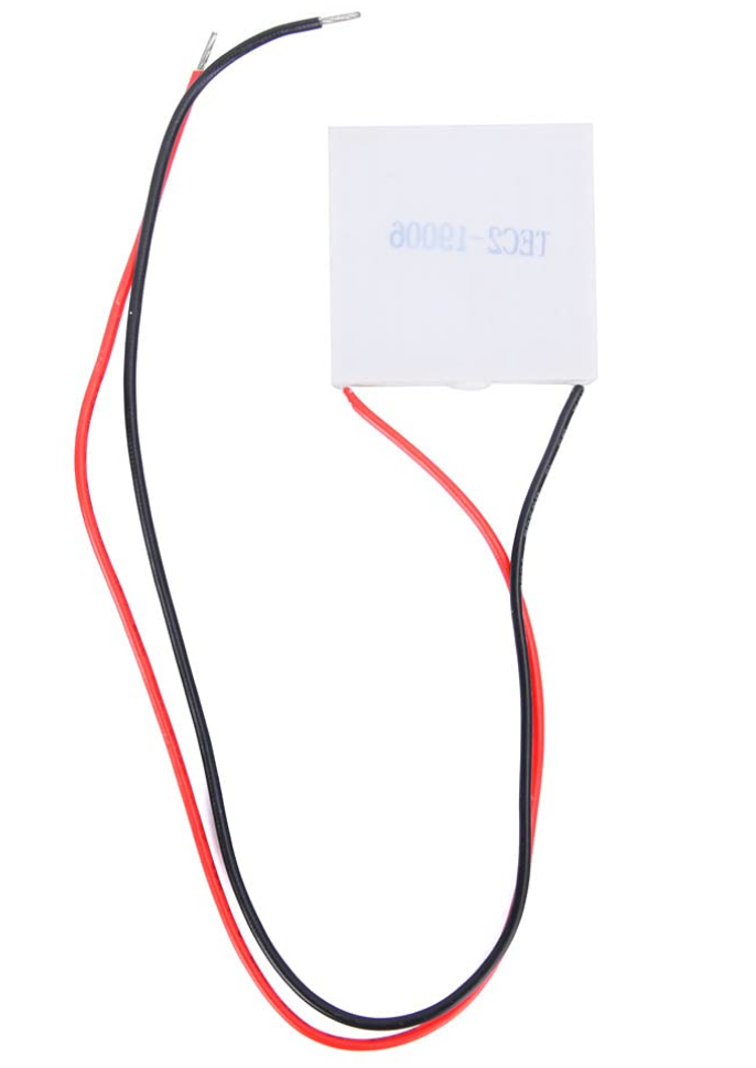

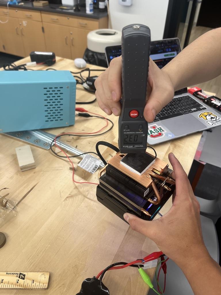

Finally, we purchased a TEC2 peltier module (image 1) which was more expensive but had a higher cooling capacity and temperature difference compared to TEC1. It can achieve significantly larger ΔT (change in temperature) suitable for intense cooling needs. We also obtained an AMD CPU cooler (image 2) from our classmate Dylan and applied thermal grease to connect the TEC2 to the cooler (image 3).
We powered both using a variable power supply (image 4) - both operated on 12V. We turned on the system for around 30 seconds and used an infrared thermometer to measure the temperature. This design finally reached -32°C, lower than the required temperature for a supersaturated alcohol mist! The cooling testing stage is over at last.
3D Printed Components

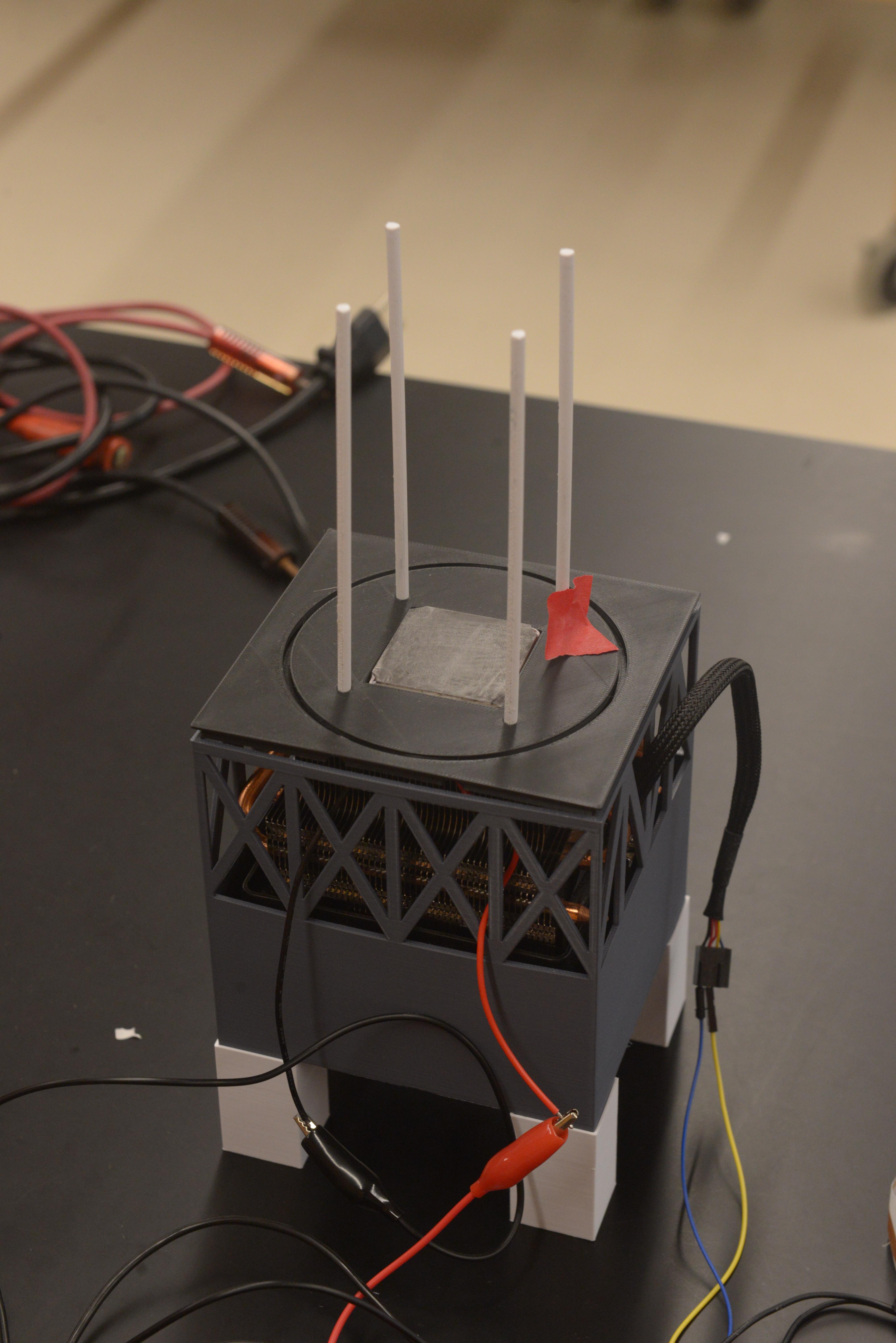
We eventually arrived at these models after a full cabinet of failed designs. The attached STL files are the parts we used for our final demonstration. The cooler support holds the CPU cooler and elevates the fan. 4 extension feet are used to further allow air flow below the cooler. The glass support should tightly fit the 7" x 4" glass dome linked in the supplies section. We also printed 4 rods to attach to the glass support, which is used to hold the sponge high in the glass dome.
Radiation Source
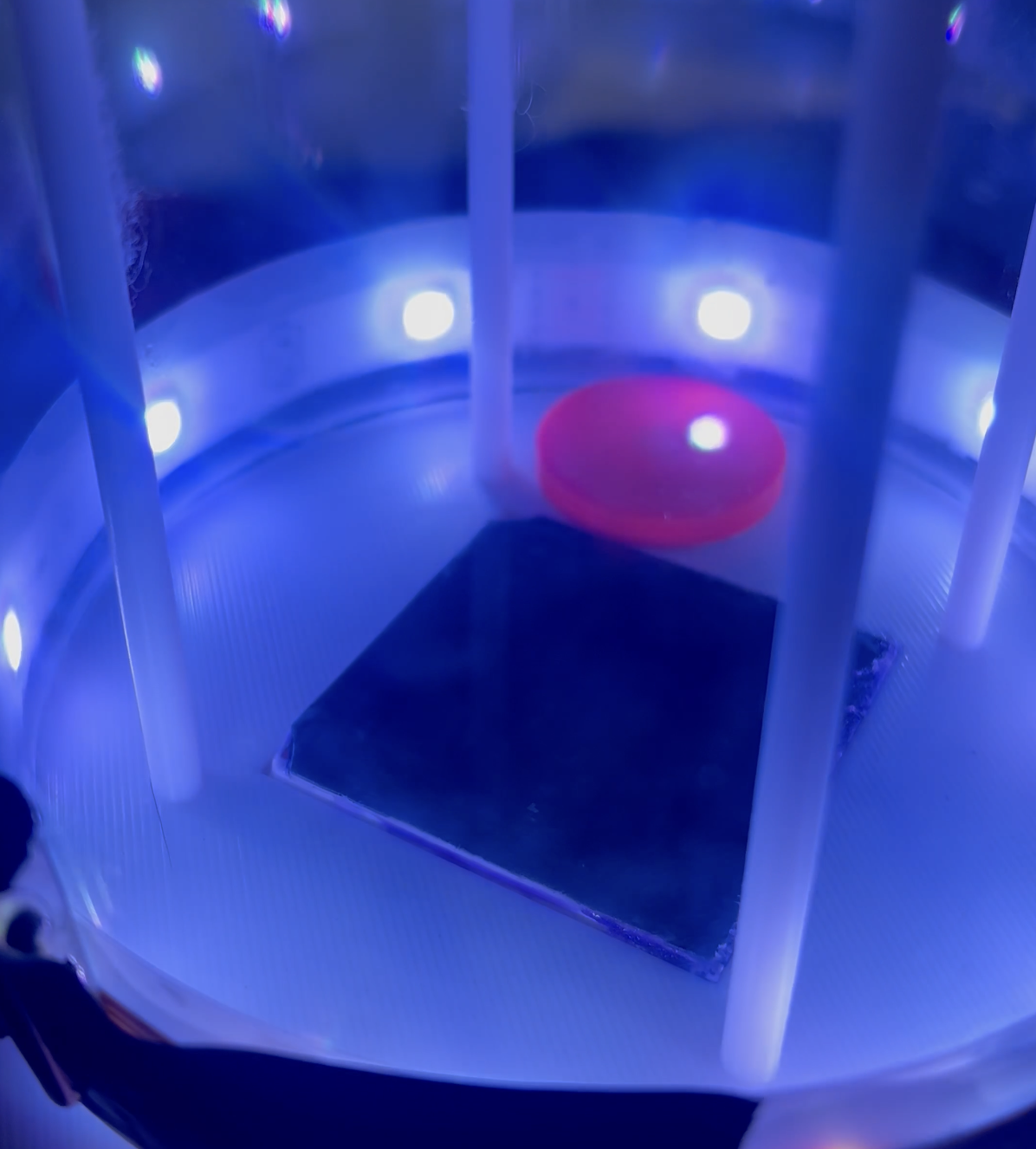

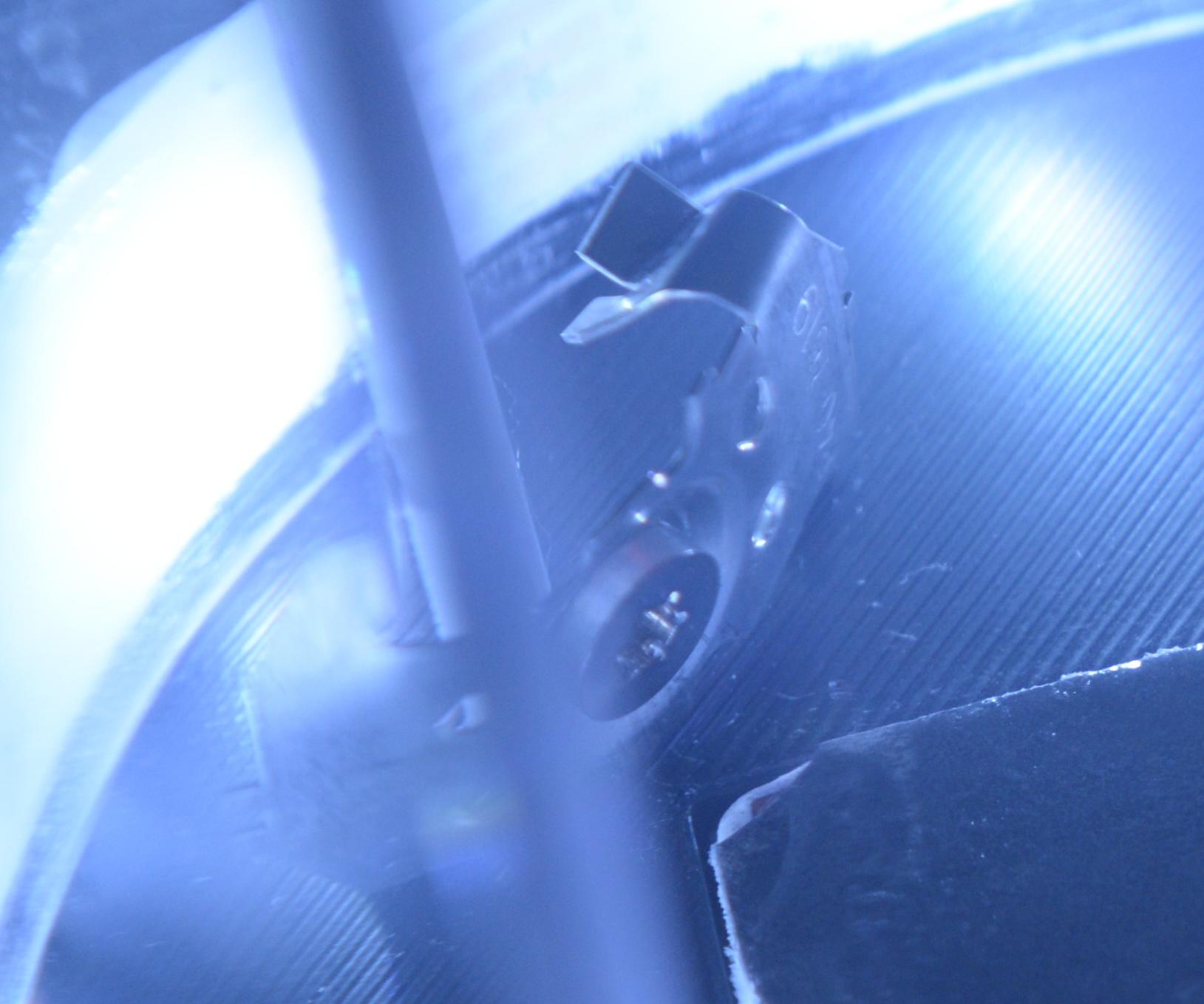
Don't be scared just because a radiation source is involved, you just need to be careful with containing them. We experimented with two types of radiation: gamma and alpha.
Picture 1: Gamma rays can penetrate through most materials, hence we stored the source in a dense shielding material as our physics teacher instructed. He also provided this source for us. We only exposed the source for short durations.
Picture 2 & 3: For our final demonstration, we decided to use an alpha radiation source americium-241 from an ionizing smoke detector for better visualization purposes --- alpha rays are larger therefore more evident. My physics teacher, Dr. Peterson, cracked open the smoke detector methodically (with a hammer) after I bought it from Lowe's, and the metal container (Picture 2) of the alpha radiation source was clearly marked. We used a large spudger to wedge open the metal container and obtained the source (Picture 3). Alpha radiation is safer as it wouldn’t penetrate past the glass dome nor could it enter human skin. They still pose risks if inhaled or entered through wounds, so it is critical to store the source inside the chamber or in a container.
Lighting


Powering a commercial LED strip is straightforward: 4 copper soldering pads indicate the positive voltage supply, red channel, green channel, and blue channel. We soldered one wire to the voltage pad (the power source for the LED strip) and another wire to the blue channel pad (to control the blue light). Then, we used alligator clips to attach the wires to a battery (12v) — connecting the wire from the voltage pad to the positive (red) terminal and the wire from the blue channel pad to the negative (black) terminal.
Note: make sure to cut the LED strip only at the designated cutting sections where the electrical circuitry is properly divided!!
To diffuse the LED, I cut a strip of printer paper around the width of the strip and glued it to the glass dome via hot glue. Then, I hot-glued the strip onto the paper ring. Surprisingly this method diffuses the LED fairly well compared to the other methods I have experimented with (sanded glass and translucent film).
For our final demonstration, the LED strip was connected to the variable power supply along with the peltier and the CPU fan.
Assembly

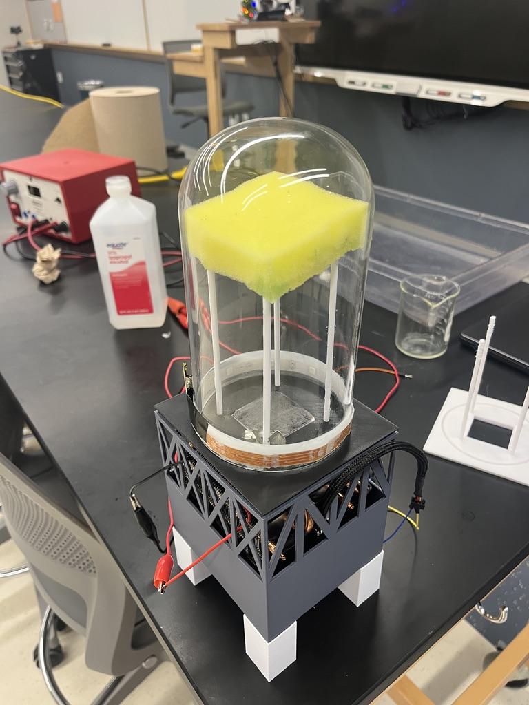

Picture 3 shows an assembled image of the chamber. To assemble the chamber, follow these steps:
- Suspend the CPU cooler with the peltier module in the cage to allow airflow under it. It should fit smoothly
- Attach the 4 printed legs/feet to the bottom of the cage with a glue of your choice, we used hot glue
- Fit the cover / dome support piece on the peltier & the cage
- Attach printed rods to the cover / dome support piece
- Soak the sponge with ~10 mL of isopropanol alcohol and place it on the rods
- Place the radiation source carefully next to one of the rods, facing it toward the center of the chamber
- Fit the dome onto the cover piece
- Use alligator clips to connect the positive and negative ends of the CPU cooler, the peltier, and the LED strip respectively to the power supply, which should be turned on at 12V
After assembly, it was time to test whether the particle tracks would actually form.
Trials
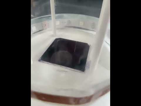
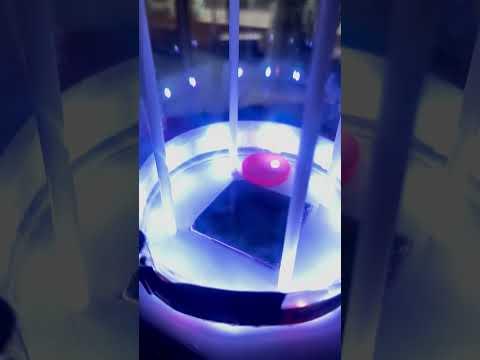

The videos respectively show:
- Our first trial with no radiation source
- A "failed" trial with a gamma radiation source
- Our final trial demonstrating the functional chamber with the alpha radiation source
Clip 1. On the first run, we could see a mist and some mystery cloud-like structure. This was due to leakage below the Peltier. However, it was still exciting to see the cloud chamber function with the desired mist for the first time even without a radiation source. The white 3d print and dirty glass also impaired visualization.
Clip 2. The gamma radiation source disappointed us. The tracks were minimal and unable to be captured on camera due to the smaller nature of gamma rays. Also, gamma rays take a longer series of events to interact and release an electron to form a streak. It was amazing to see particle tracks for the first time though!
Clip 3. Ultimately, we achieved great visualization switching from a gamma source to significantly larger alpha radiations produced by americium-241 from the ionization smoke detector. We also switched to using black 3d prints and cleaned the glass dome. We realized that the cloud structure in the initial run wasn’t necessary to detect particles, as the nucleation sites will only occur on the particle track. As long as the mist is supersaturated, there will be visible marks from the radiation source.
Final Words

Building the thermoelectric cloud chamber was incredibly rewarding: we became familiar with radiation, supersaturated vapors, radiation sources, elementary circuitry, 3d modeling, and effective communication between partners. Presenting the visible particle tracks to our class was exciting, and finally visualizing the alpha particle rays consistently was the best reward for our efforts.
To potentially improve this project, more peltiers could be used to increase the effective detection area of the chamber. This would also require a cooling solution that covers more surface area, which could take the form of a compressor. A high-voltage grid could be used to increase track visibility. For a fancier chamber that could run continuously for long periods, an alcohol circulation system could be designed.