The Wolverine-scratcher 2000
by TheFancyKitten in Craft > Printmaking
403 Views, 0 Favorites, 0 Comments
The Wolverine-scratcher 2000
This is the guide for building your very own wolverine-scratcher.
But first things first, you'll be needing some materials:
- acces to one 3D-printer
- 1 "Arduino starter kit"
- acces to one computer which has "Arduino IDE" installed.
- 2 screws (4 mm in diameter)
- 1 screw (3 mm in diameter)
- 1 9-volt nattery
- 1 9-volt adapter
- 1 handdrill (4 mm in diameter)
- 1 box full of old legos
Getting Started - the Claw
Now for the manufacturing of the actual claw you will need a 3D-printer.
The file which contains the 3D-model for the claw is attached to this step.
So just print the claw using the file and the first step is finshed.
Downloads
Setting Up the Machanism - Programming the Arduino
Now we are going to program the code for the arduino.
If you have experience with coding or with arduino, you can give it a shot yourself.
If not, no worries, in the attached file is the code you need.
The code must include the following:
It needs to react to the press of a button
Once the button is pressed, the claw needs to move forward using the servo
Once the button is released, the claw needs to move backwards.
Optional:
If the button is hold down for a fixed amount of time, the claw needs to stay in the extended position.
If the claw is locked in the extended position and the button is hold down for a fixed amount of time, the claw needs to go back to the starting position.
Downloads
Setting Up the Mechanism - Servo to the Claw
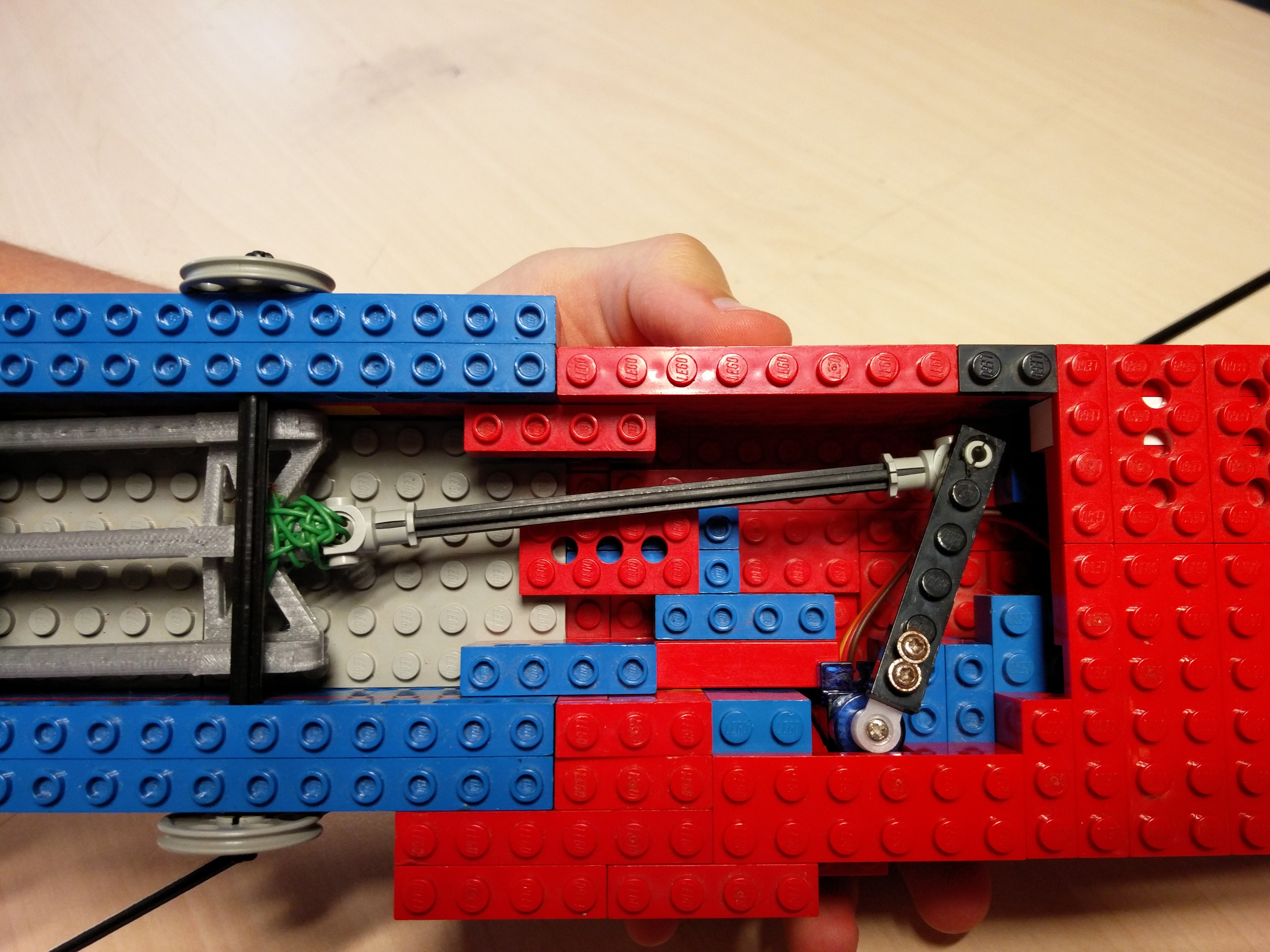
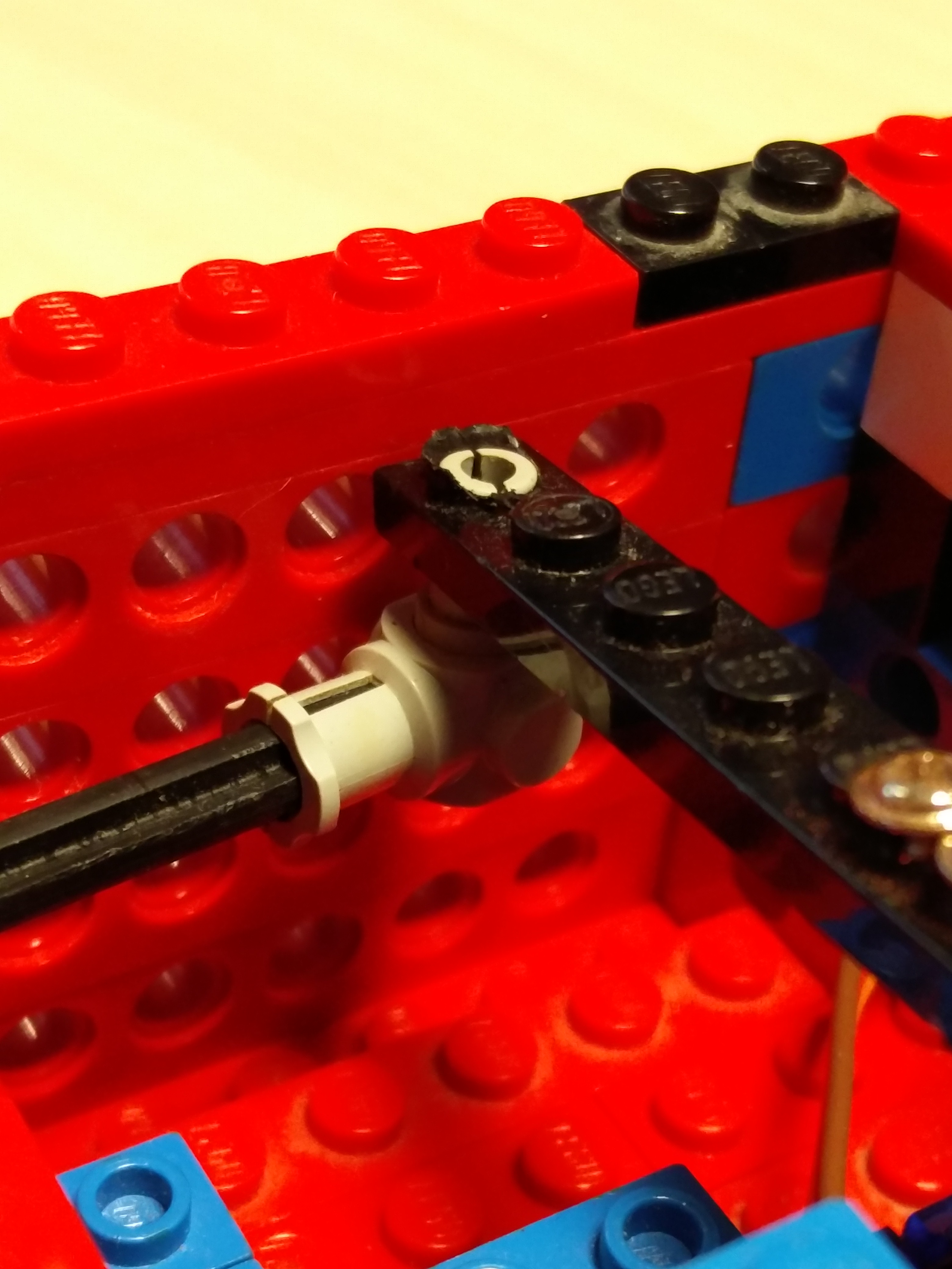
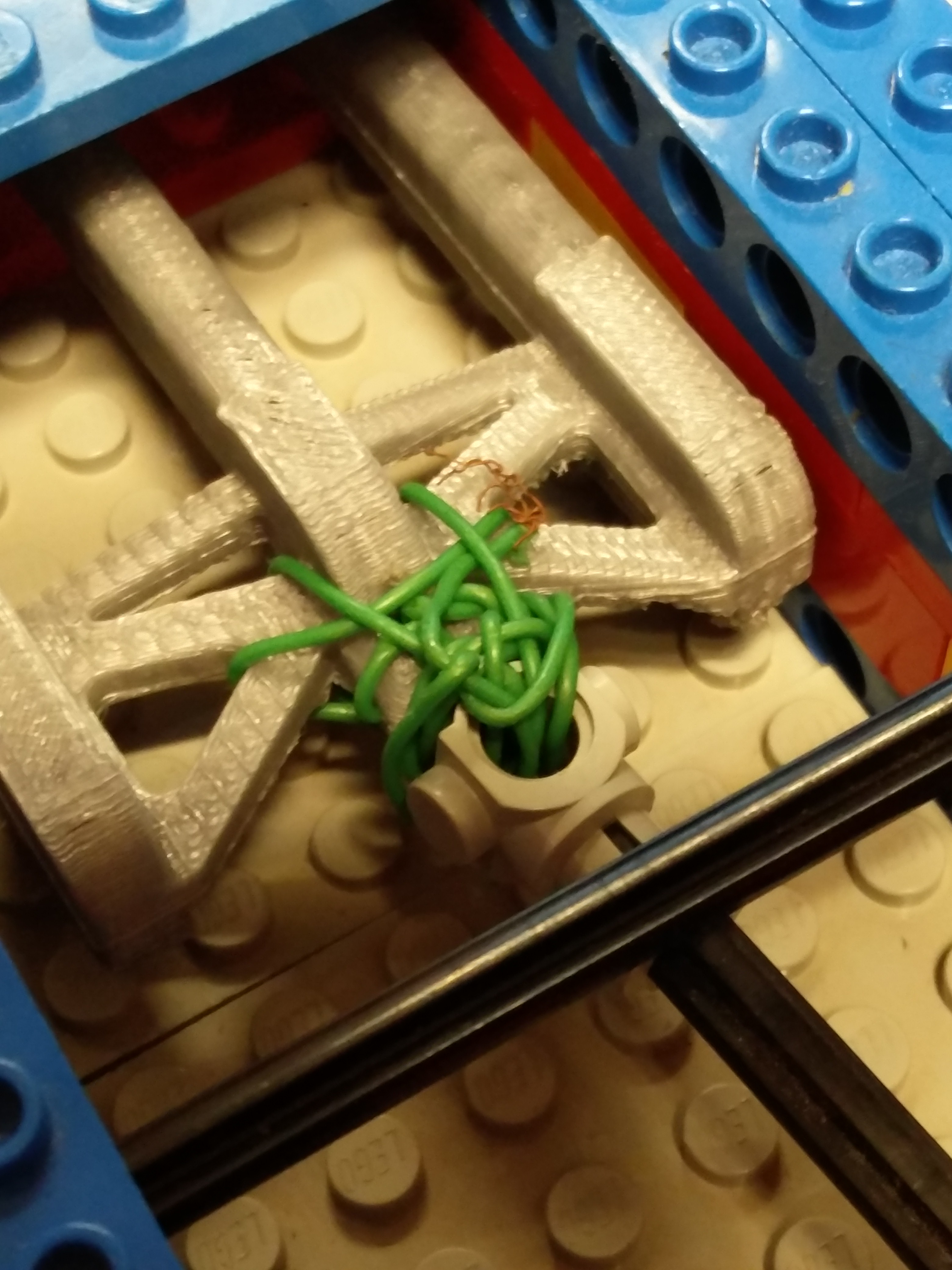
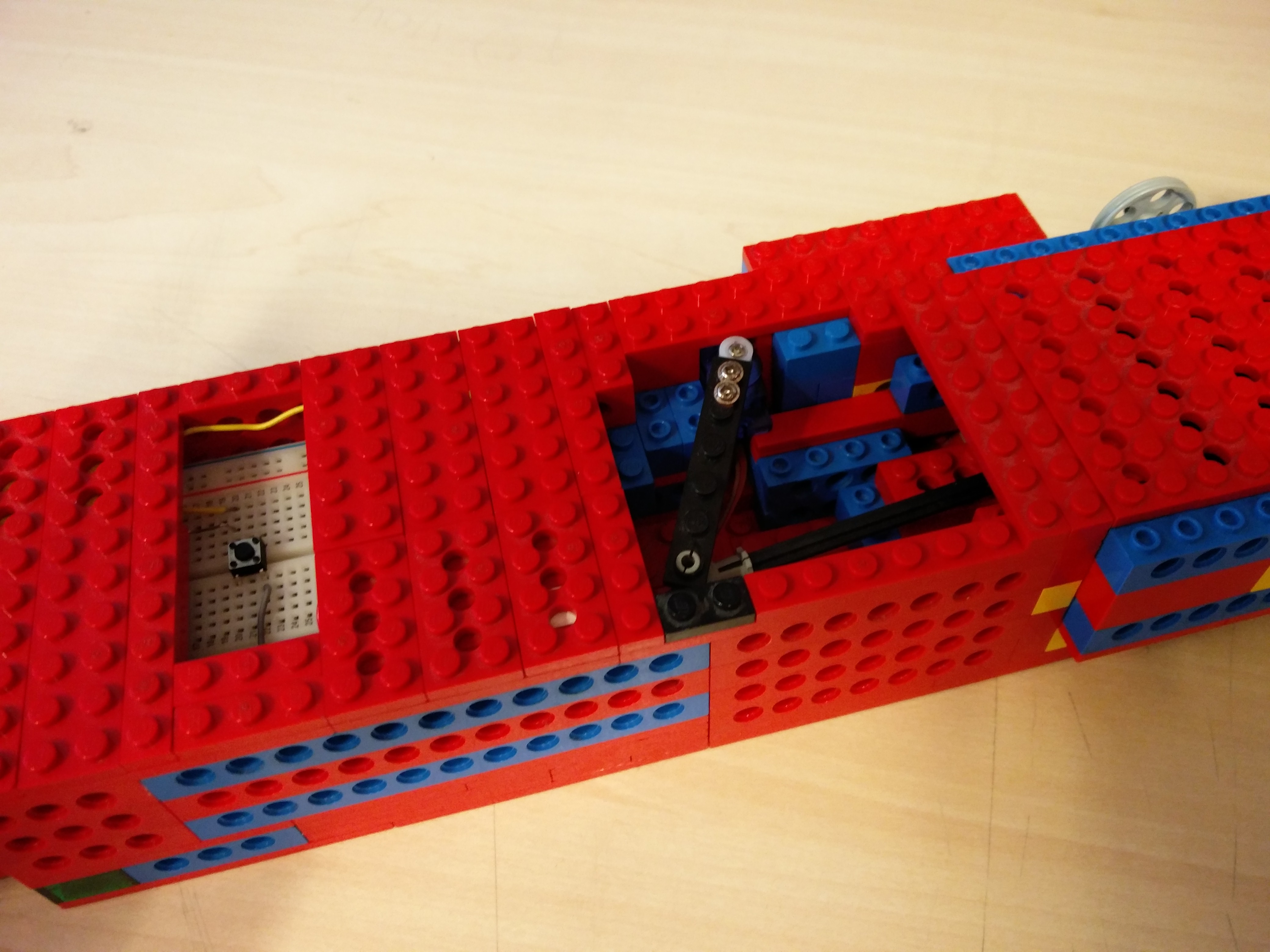
First you want to connect a servo arm (4,5 cm) using a screw. If you don't have a servo arm in this size, you can connect a smaller arm and extend it. For example by using lego or a piece of wood. (just drill two holes in it, both on one side of the piece and connect it to the servo arm using two screws) After this drill one hole on the other side of the servo arm (the side furthest away from the servo). In this hole you put a lego pin (just lik in picture two). Afterwards connect a black lego bar (10 cm) and on the other side of the bar connect another lego( the same one you used in the beginning). The lego bar will not connect correctly to the 3D printed claw so you have to connect it using rope or ducttape. We used a kind of cable (see picture 3).
Setting Up the Arduino
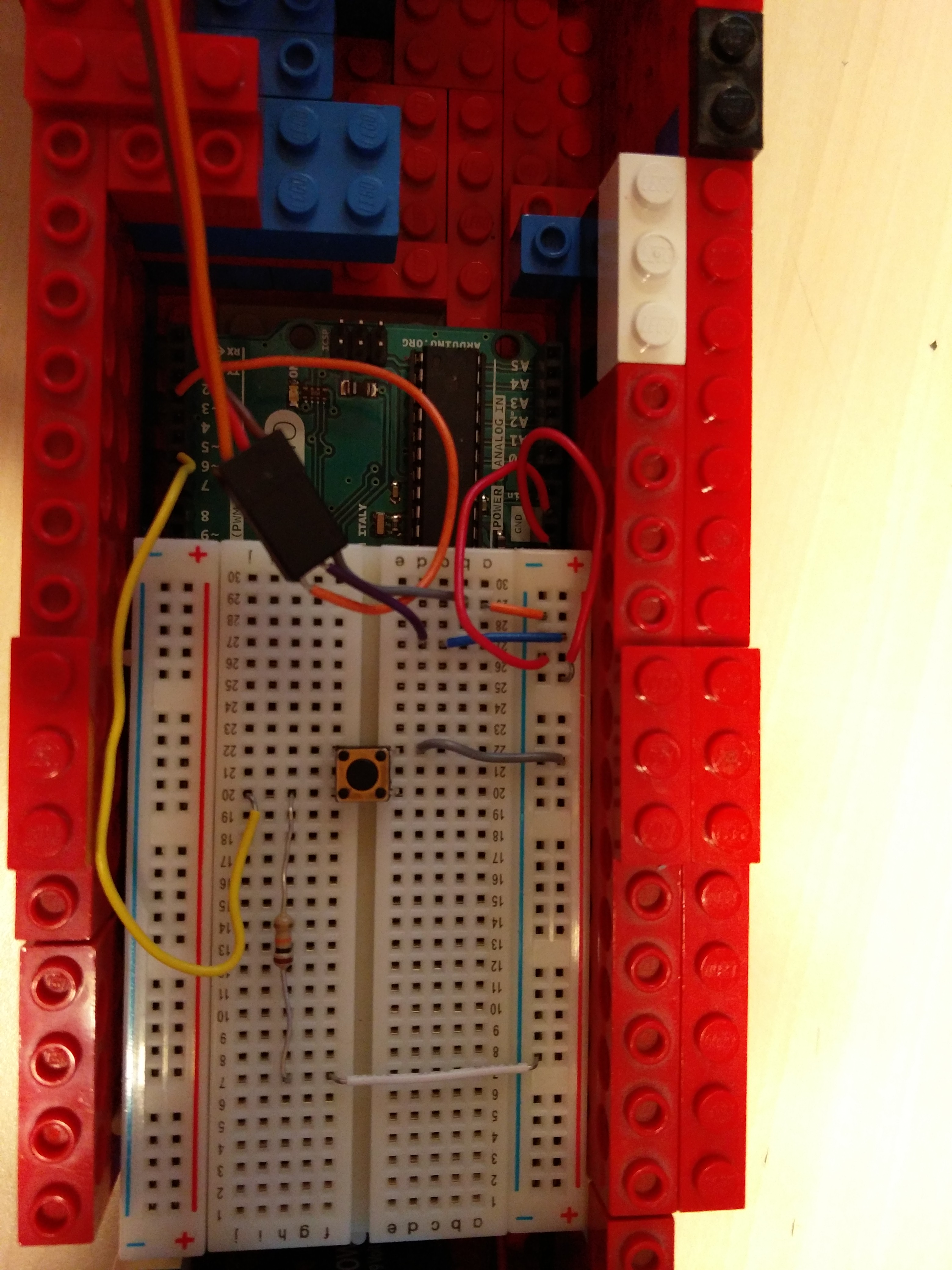
Connect the cables as seen in the picture. The only important part is that you have to use three seperate cables to connect the servo to the breadbord. You have to connect the plus cable to the 5 volt entrance on the arduino. And you hae to connect the minus cable to the ground entrance on the arduino. Connect the yellow cable to pin 6 (or whatever pin you used to control your button in your code). And connect one of the cables connected to the servo to pin 3 (or whatever pin you used to control the servo in your code).
Let There Be Light
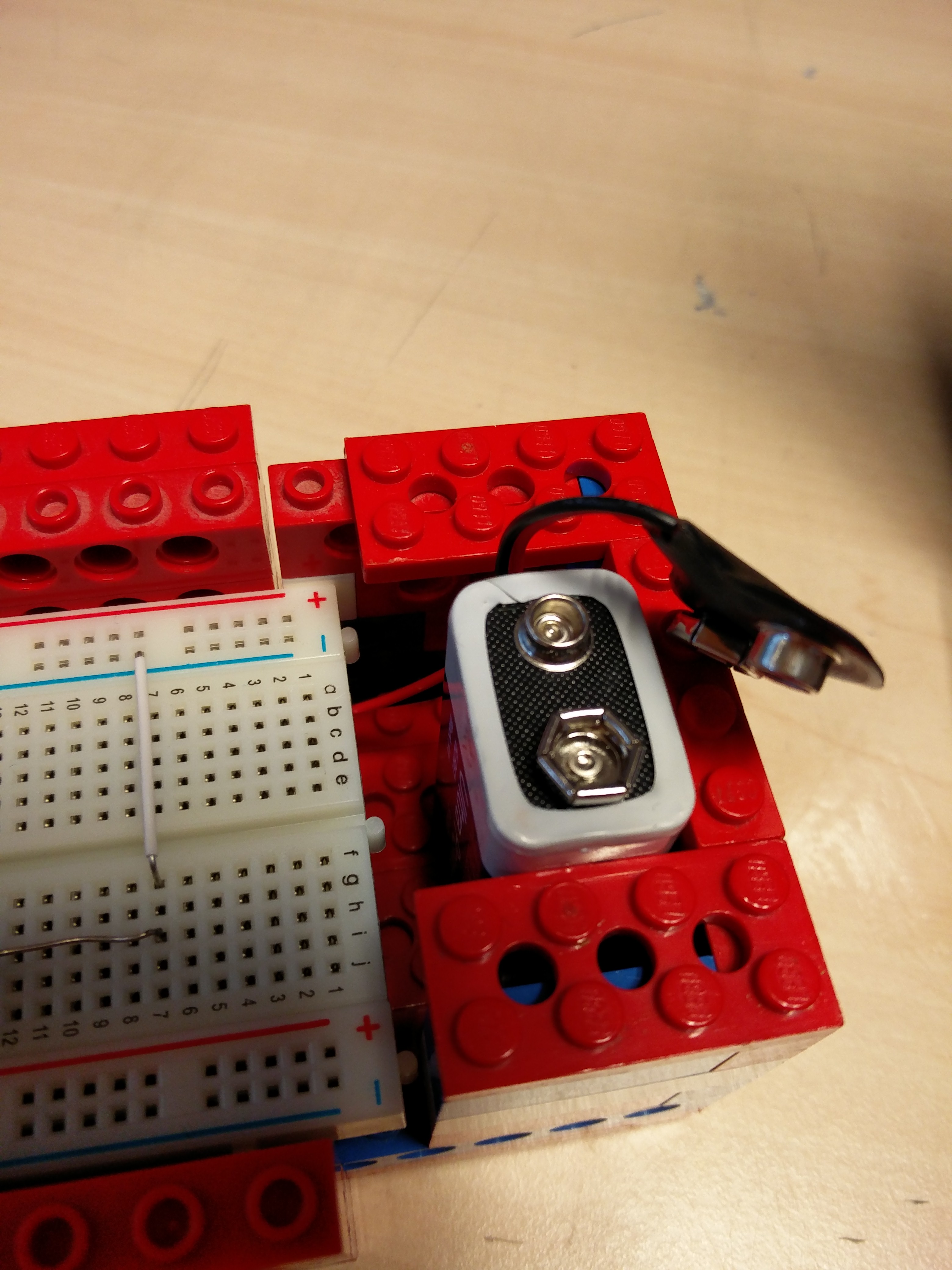
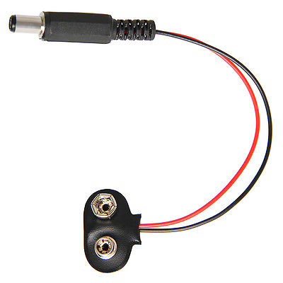
In this step you connect the 9 volt battery to the arduino using an adapter.
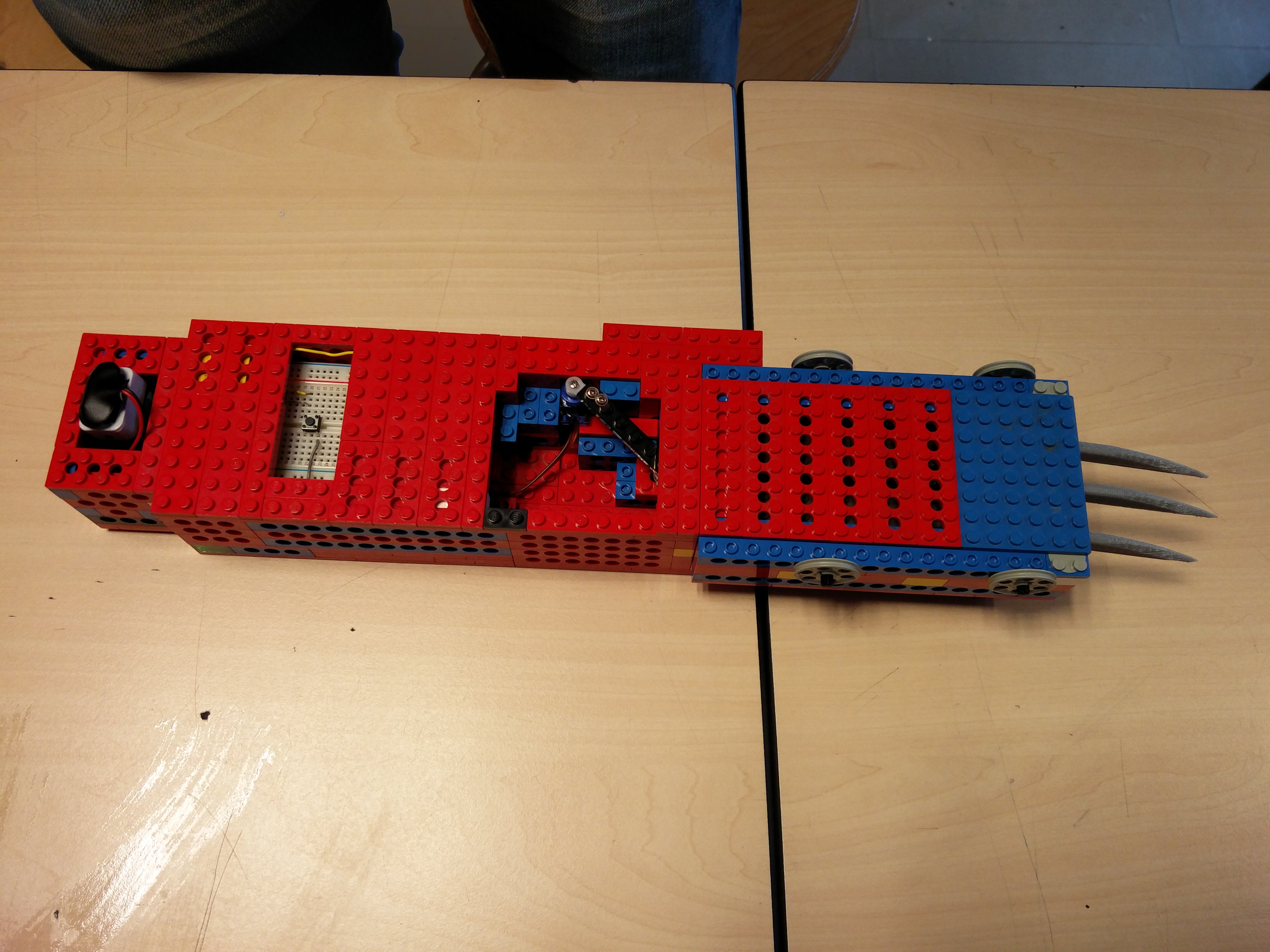
The Final Step - Pimping Your Claw
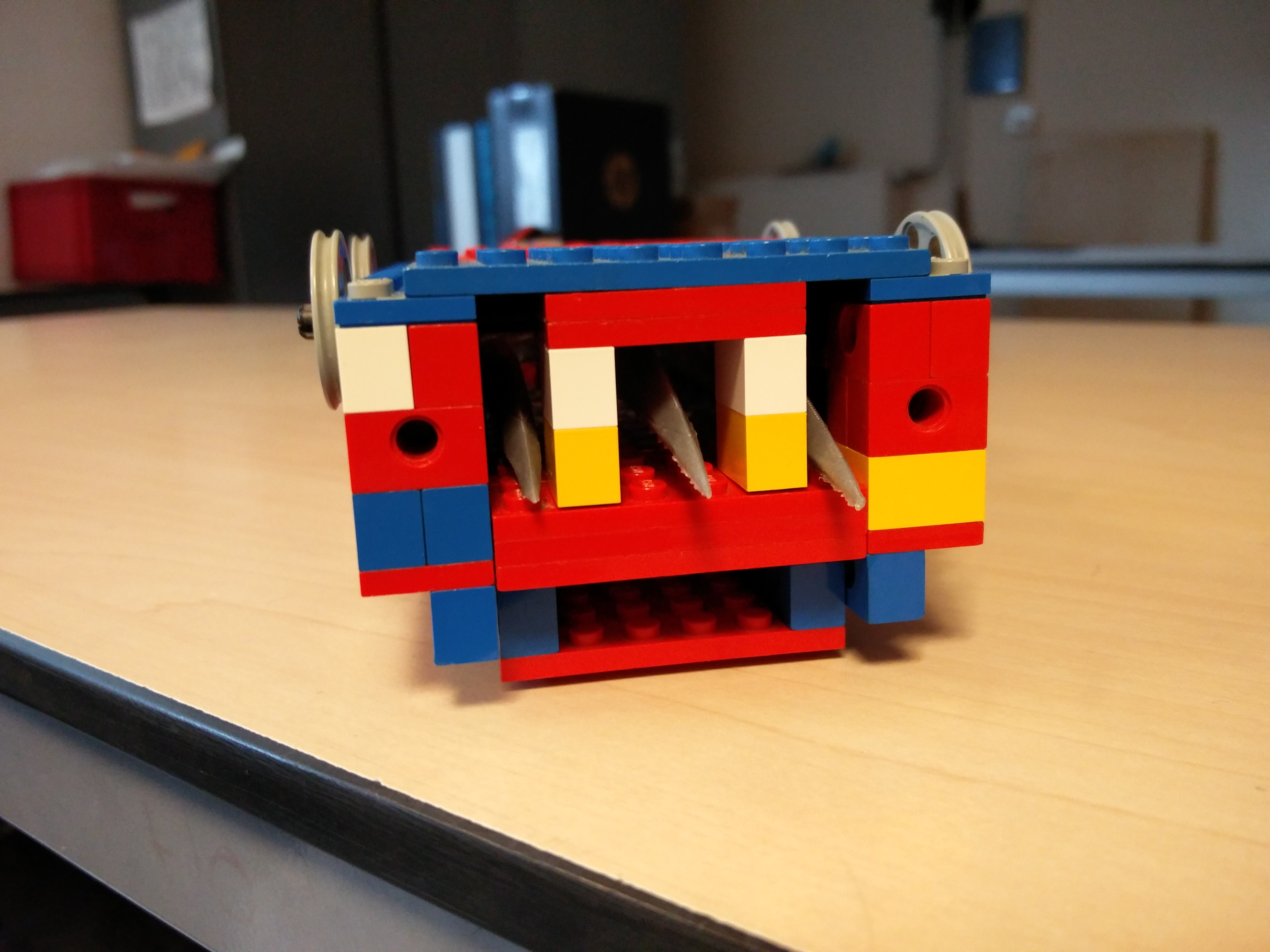
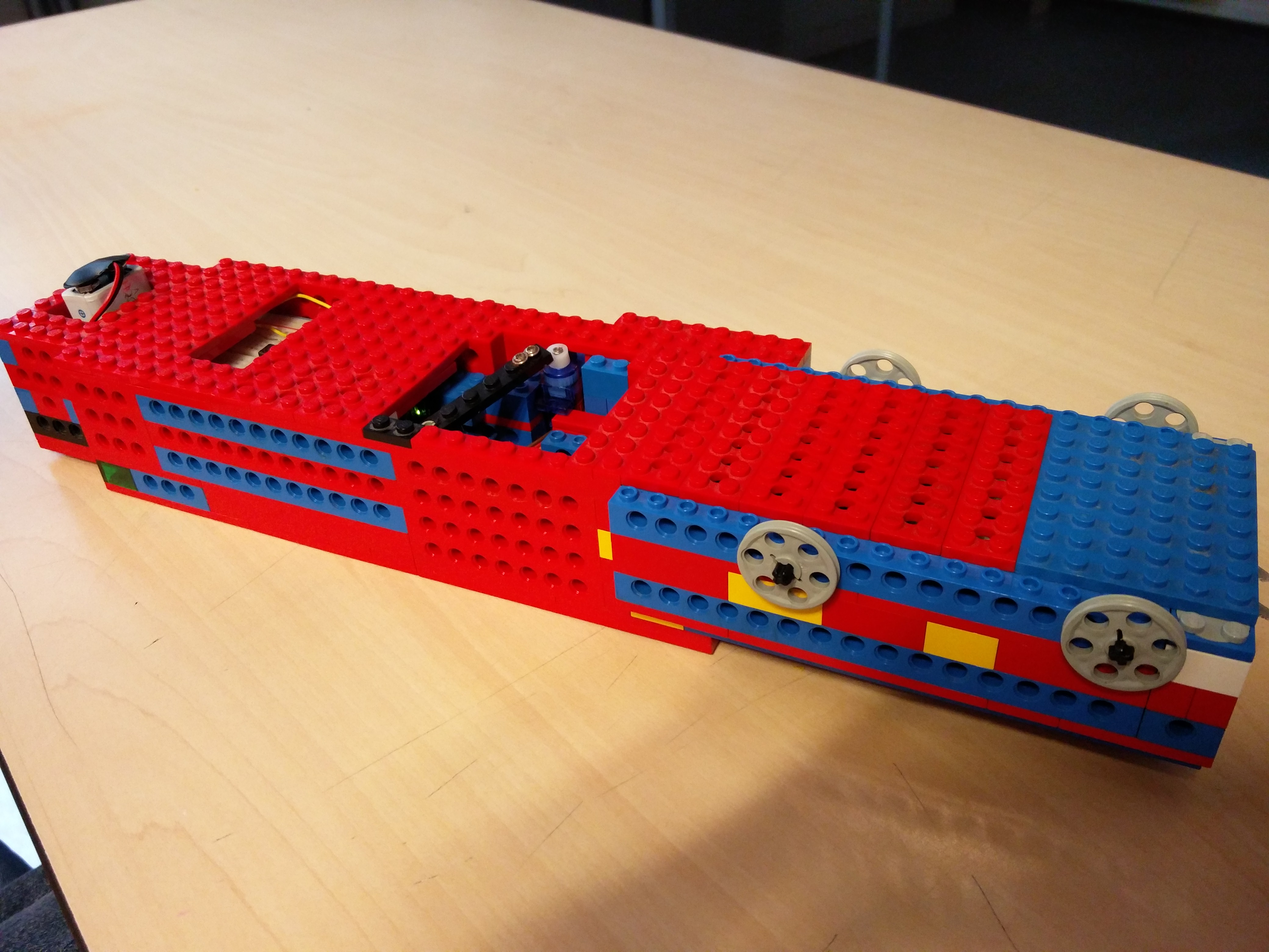
In order to complete your claw, you have to build a shell around all the electronics. This is the part where you are going to use your imagination. You can use legos, wood, cardboard, plastic boxes. We used legos (and lots of them).
Congratulations, you now have your own Claw!!!