The Vice Assembly
by corneliovazquezj in Craft > Digital Graphics
800 Views, 0 Favorites, 0 Comments
The Vice Assembly
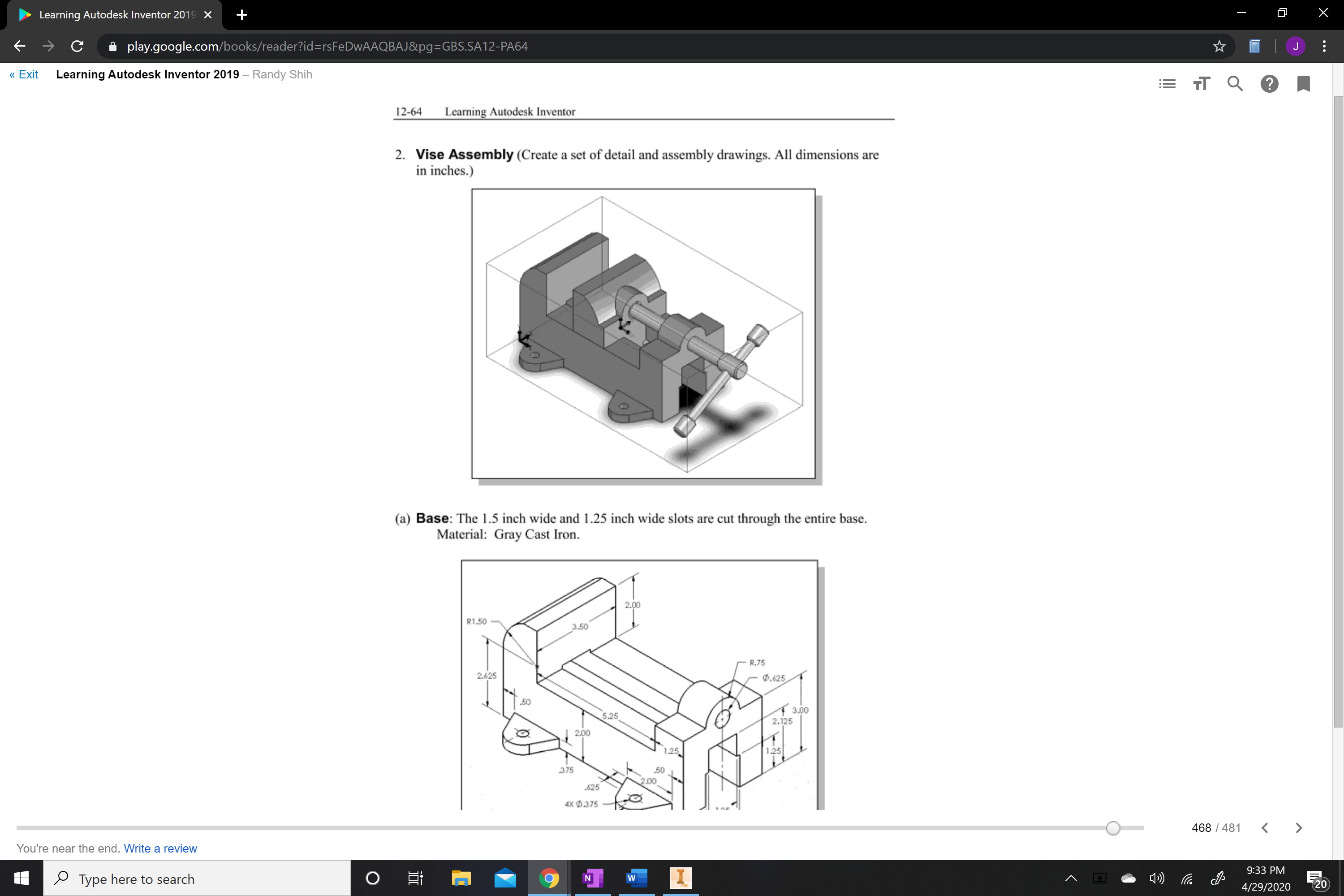.png)
This guide will help you navigate and help you assemble a part in Autodesk Inventor. The project we will be assembling will be the Vice
Supplies
You will need: laptop or computer, mouse, and the Autodesk inventor application.
Find a comfortable place to work where you will not be bothered.
Find your laptop, and mouse. Set up your area where you can work comfortable
.png)
Find the Autodesk inventor application on your screen and open it.
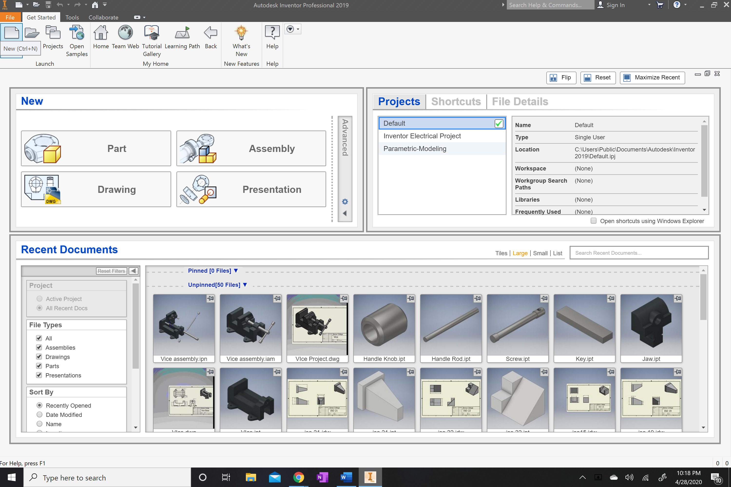.png)
Once in Autodesk inventor locate the new tab. It is located on the top far left corner of the application.
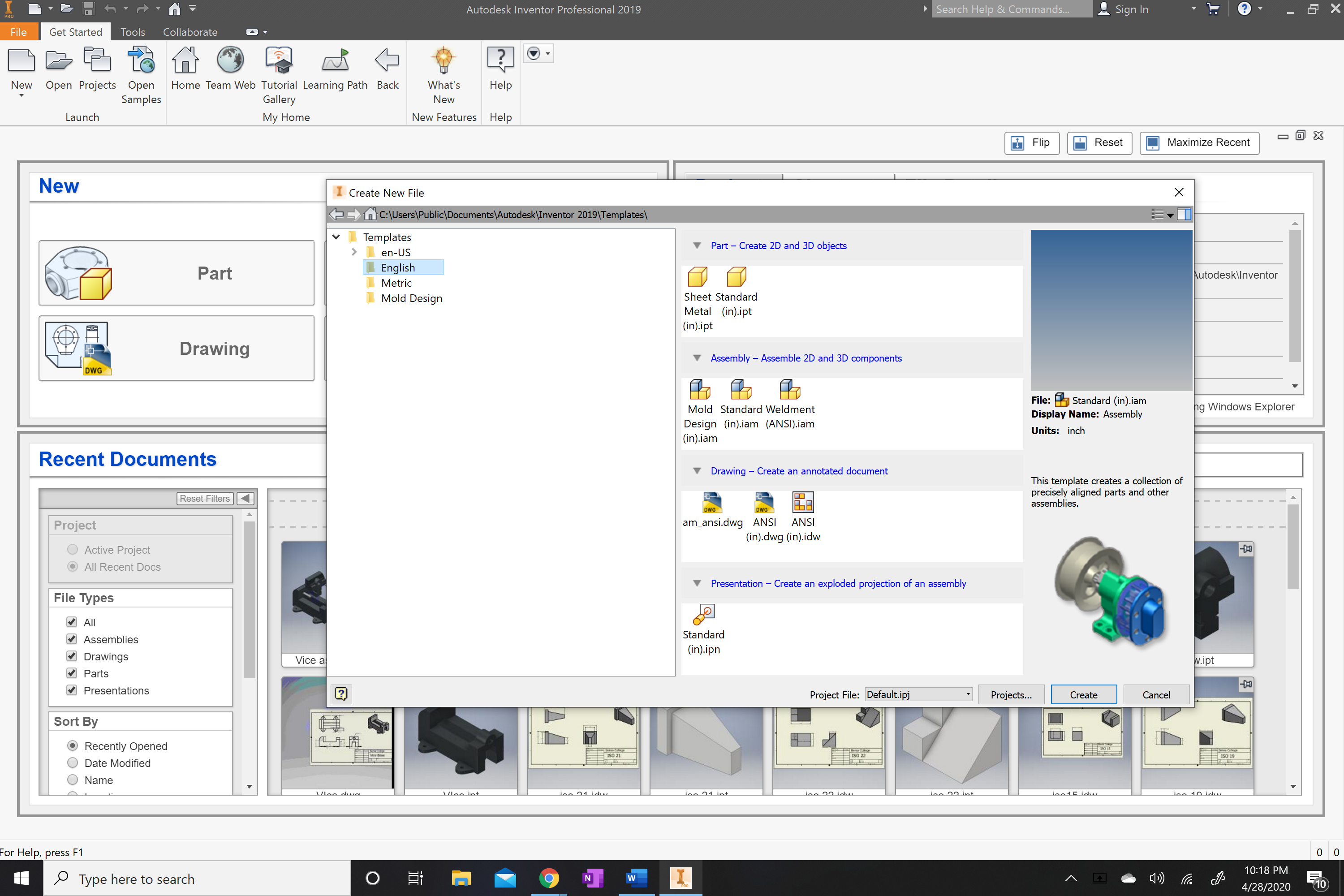.png)
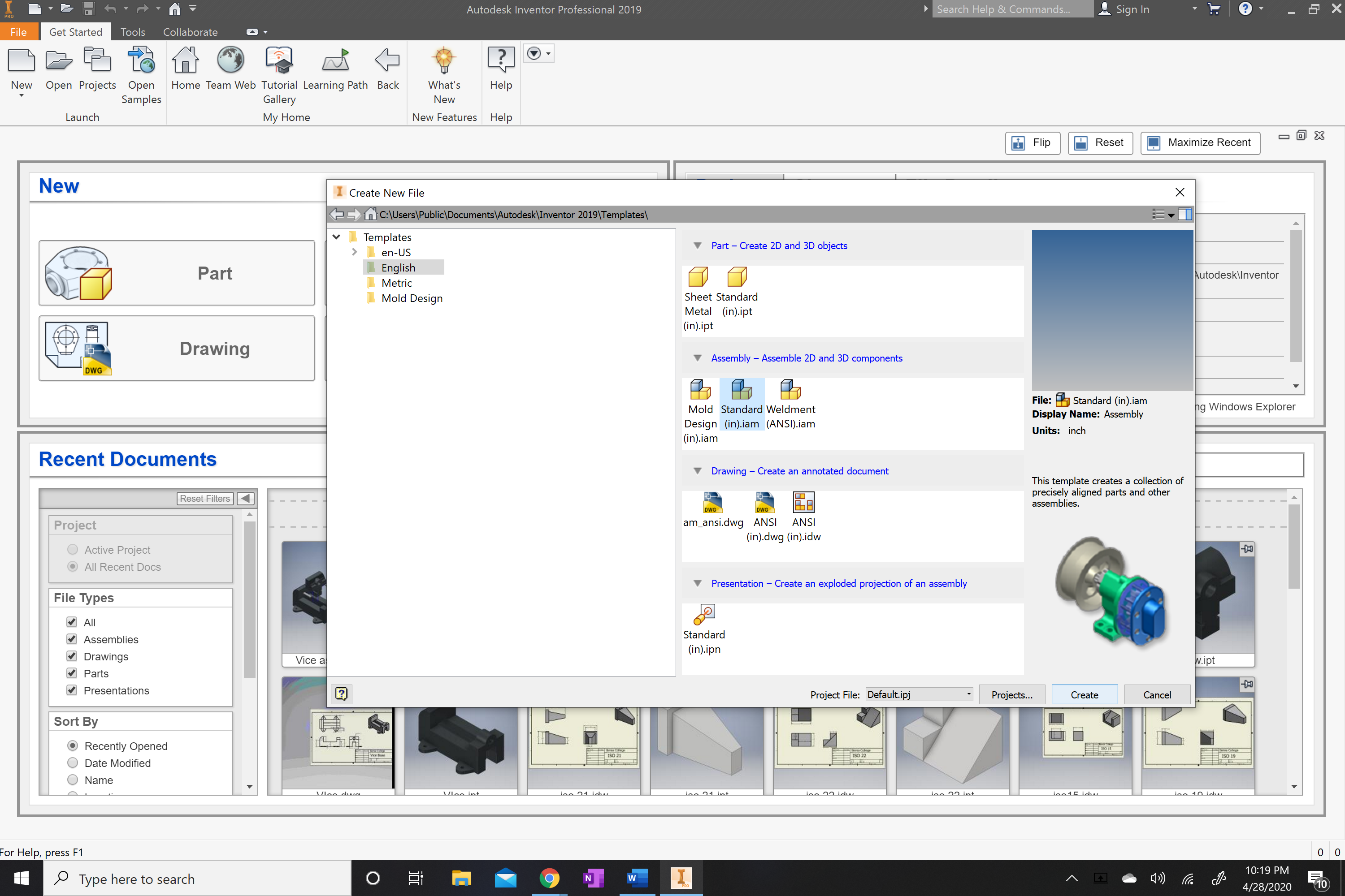
Once the tab opens up you will locate and click on English as the type of measurement.
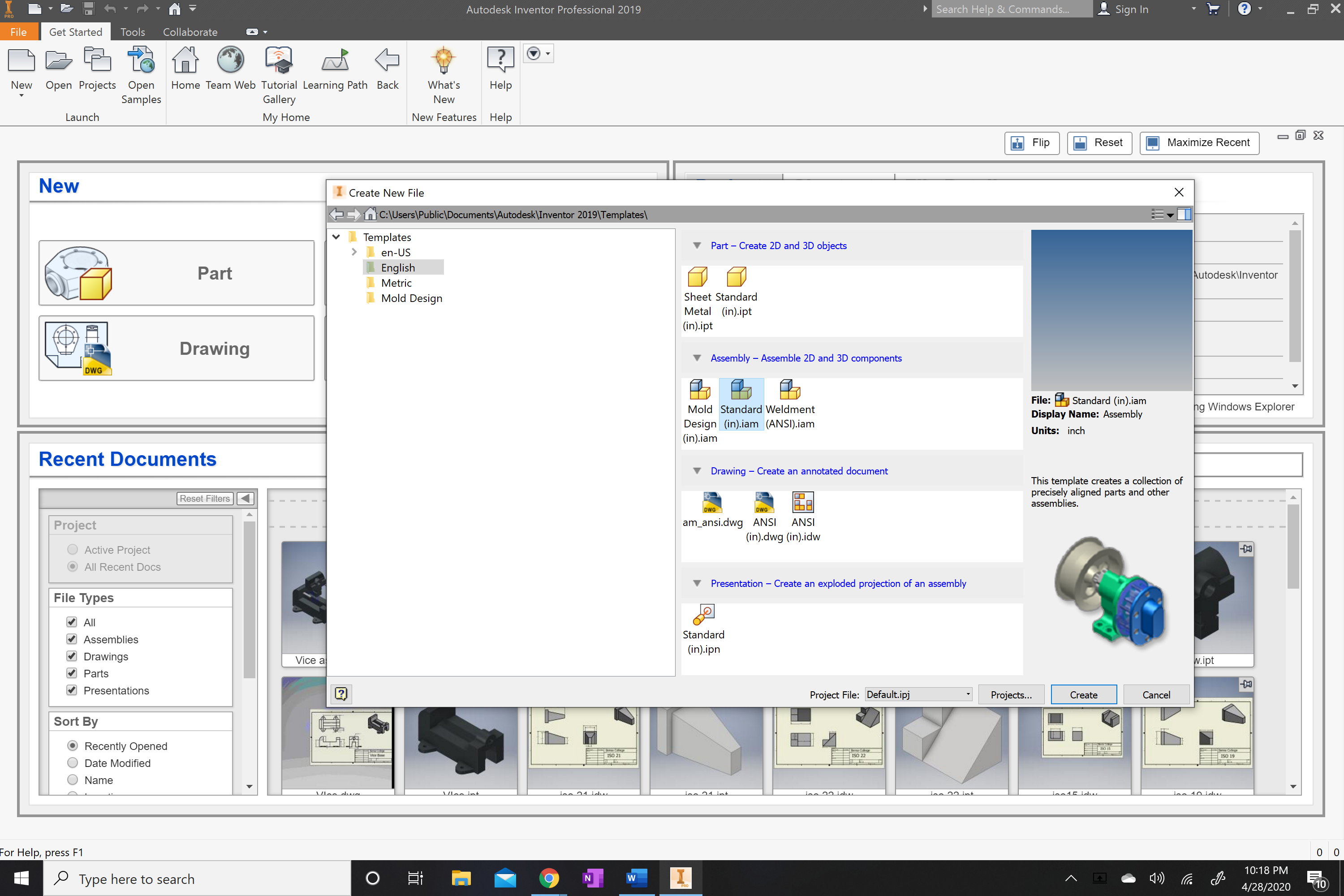.png)
Once English is highlighted move over the right side of the tab and
locate and click the Standard (in).iam, this will allow you to create an assembly.
.png)
Once English and Standard (in).iam has been selected you can now click create at the bottom of the tab.
.png)
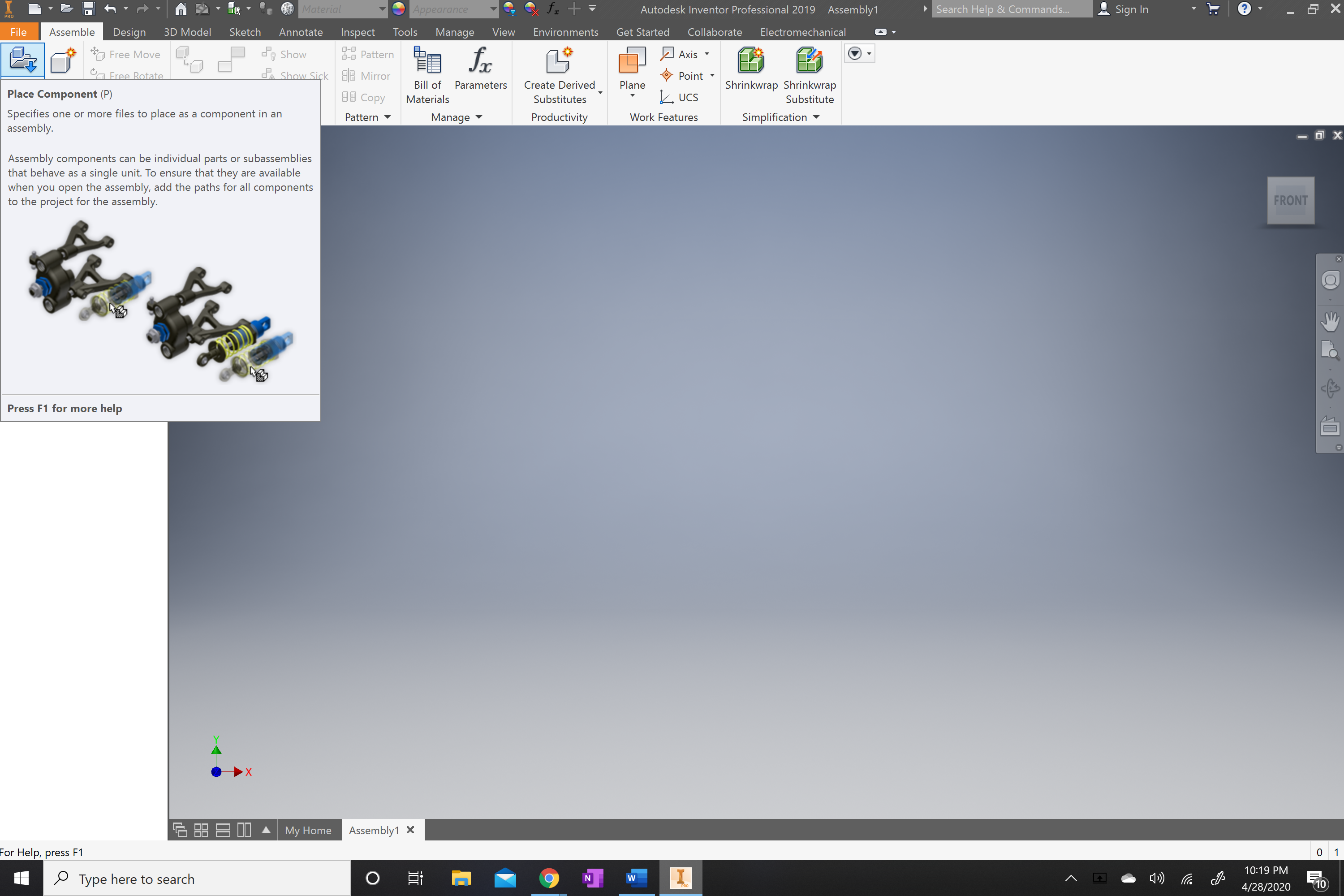
Once the tab has been created you will locate the (place) tab. This is located on the top far left of the screen.
.png)
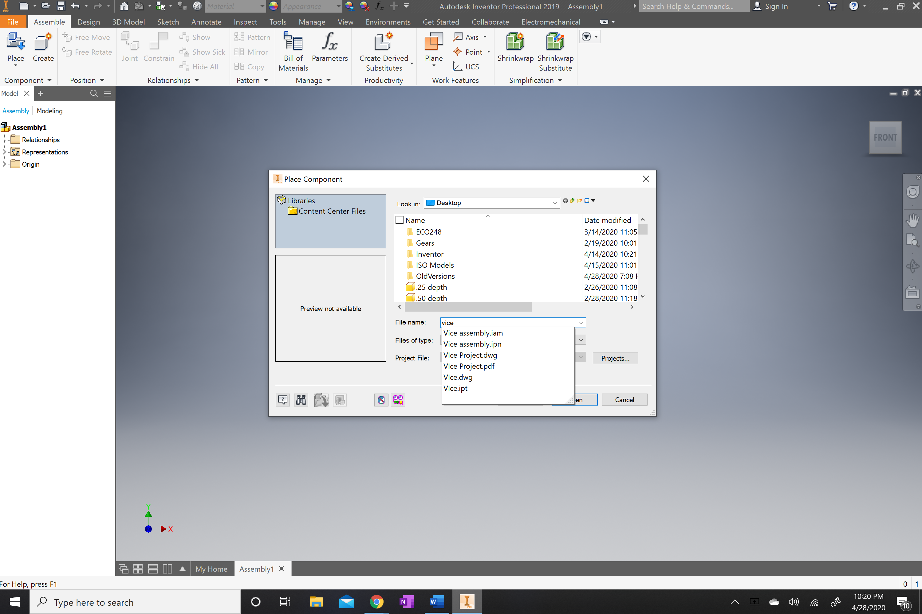
Once located you will now select it and it will open up your files.
.png)
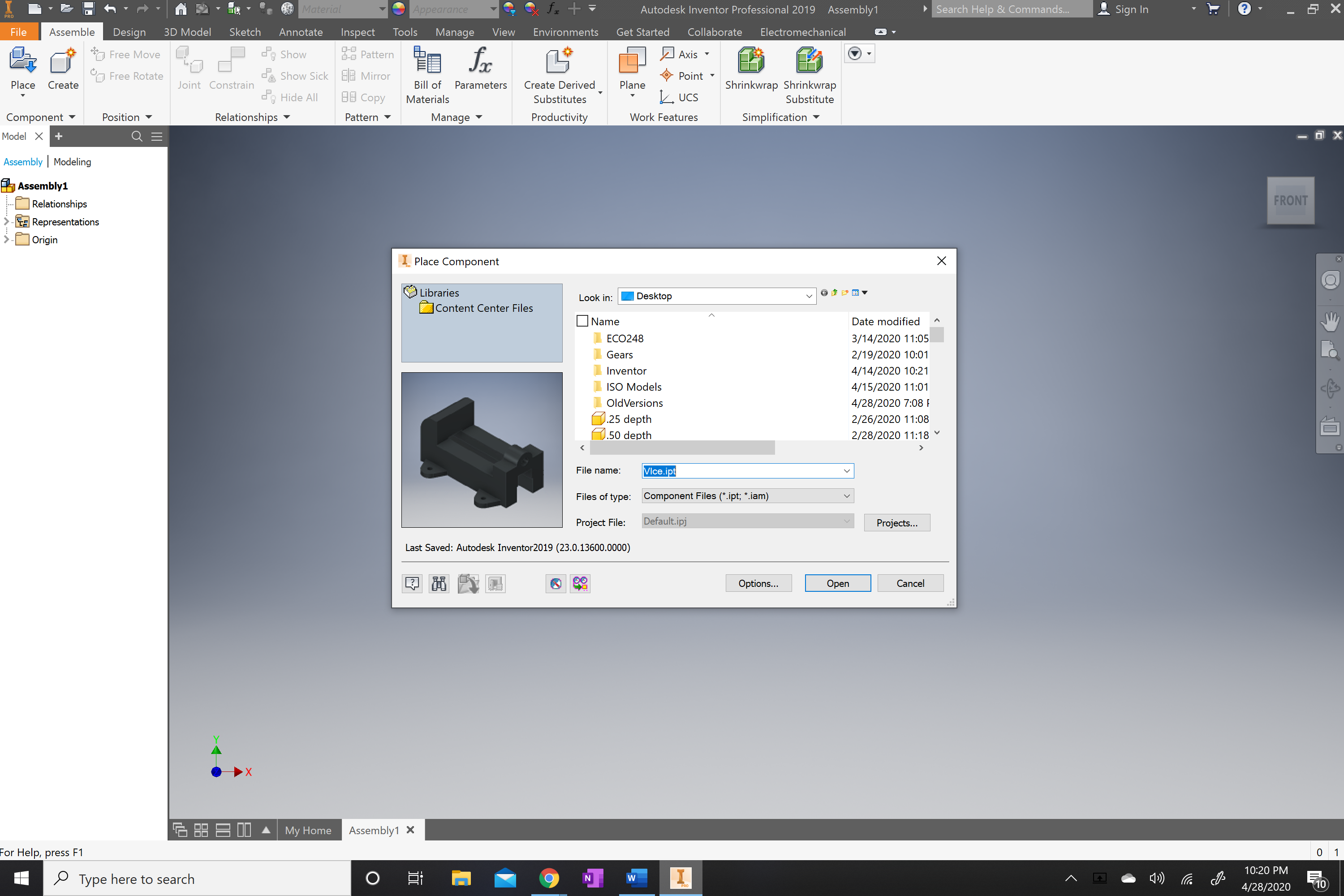
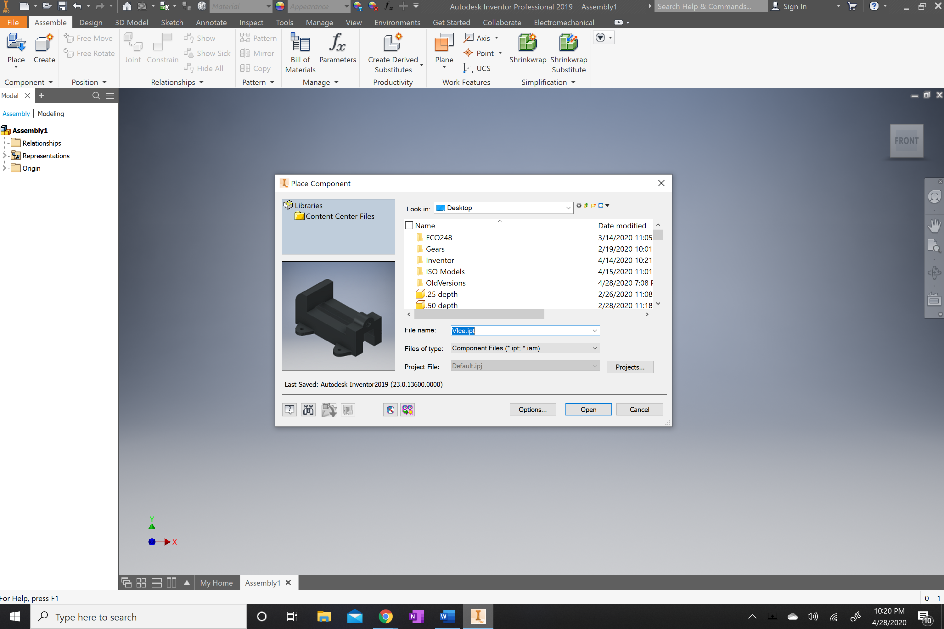
Once opened you will locate the parts for the Vice project.
.png)
The vice project will include the vice base once located in the files you will select it.
.png)
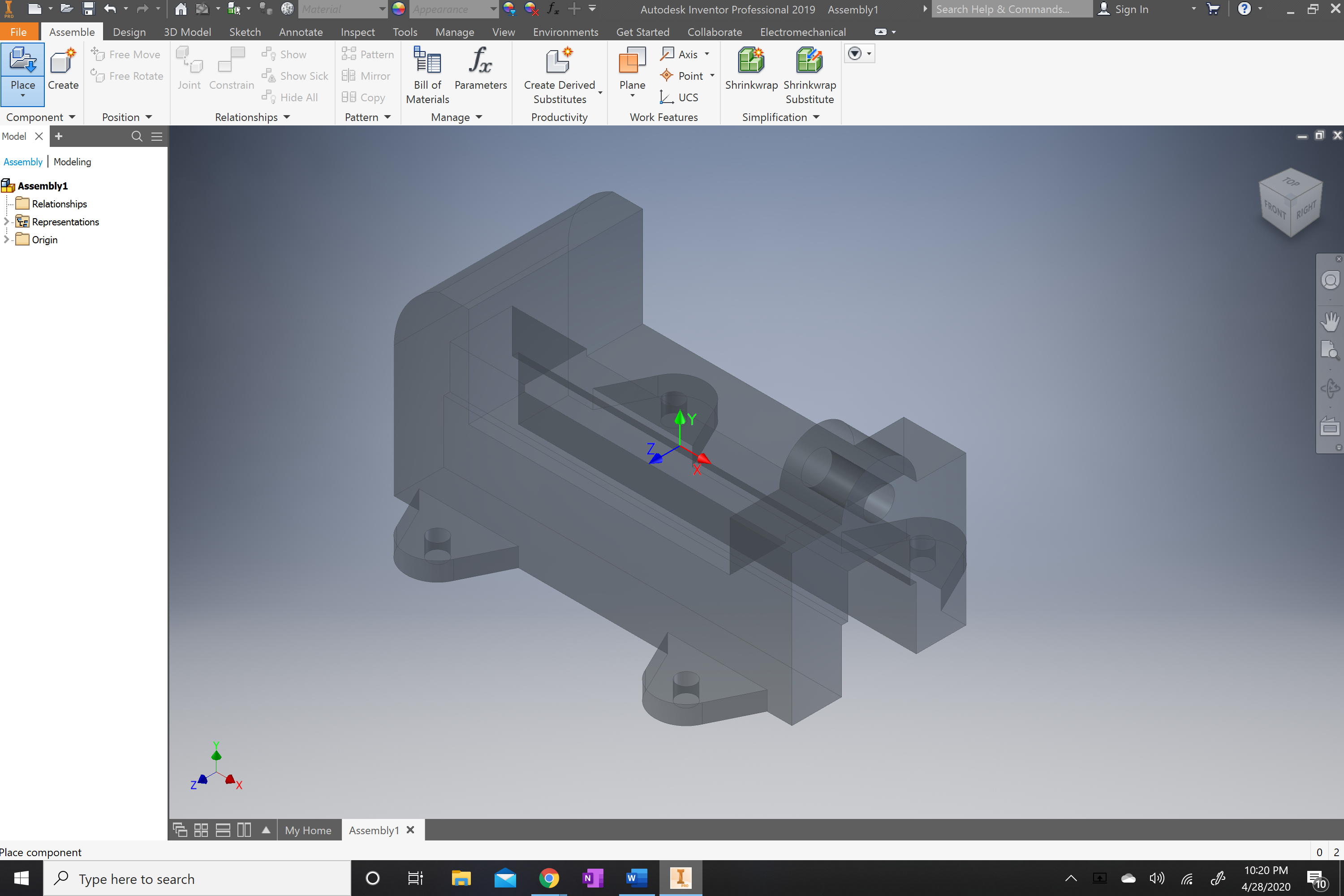
Once opened you will be able to place the vice anywhere on the screen. You will left click and it will place it on the screen.
.png)
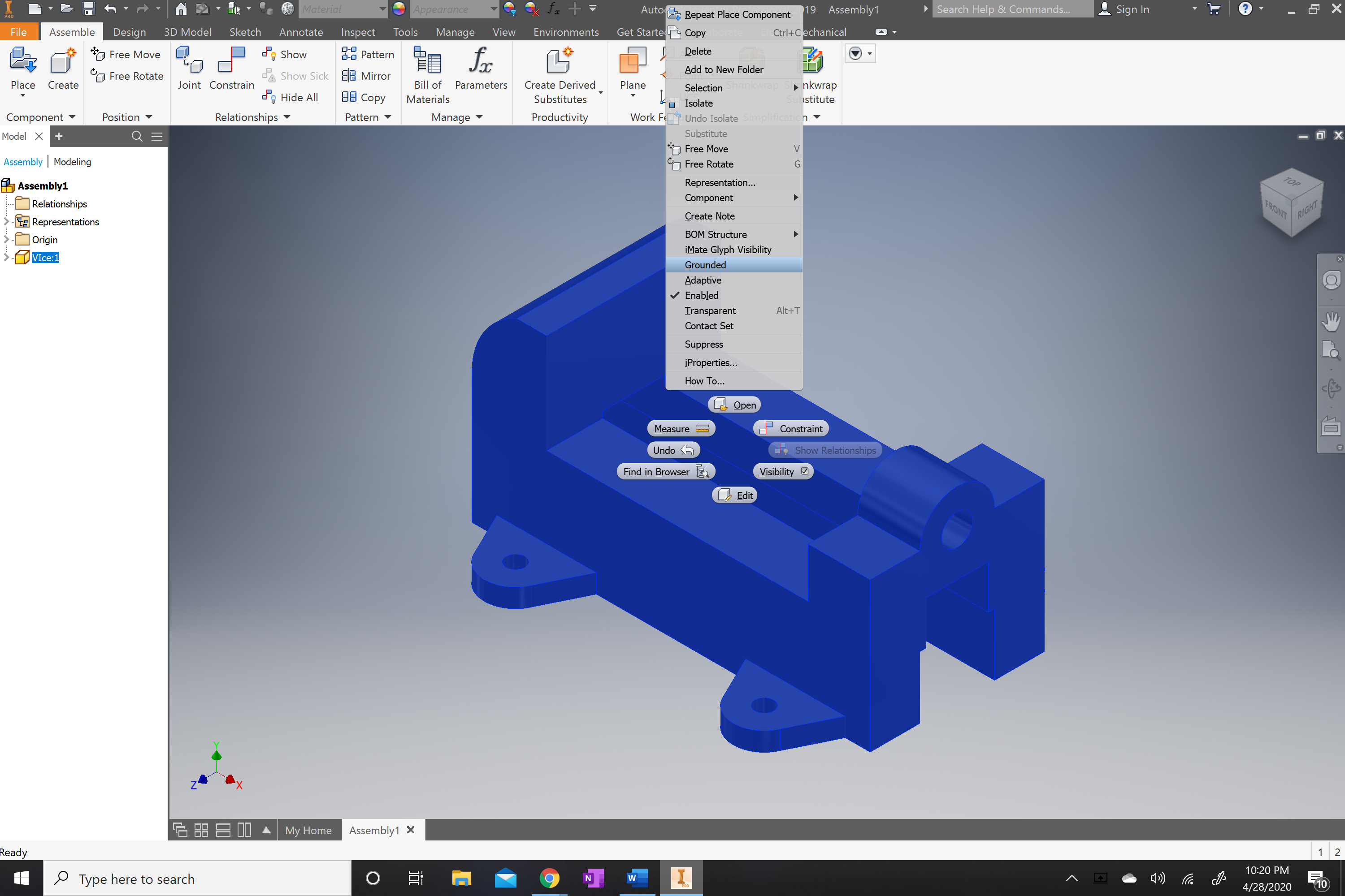
Once placed you will want it to stay put and not move so you will right click on the vice body and locate the grounded key once located, you will left click on it and the part will be grounded in the space.
.png)
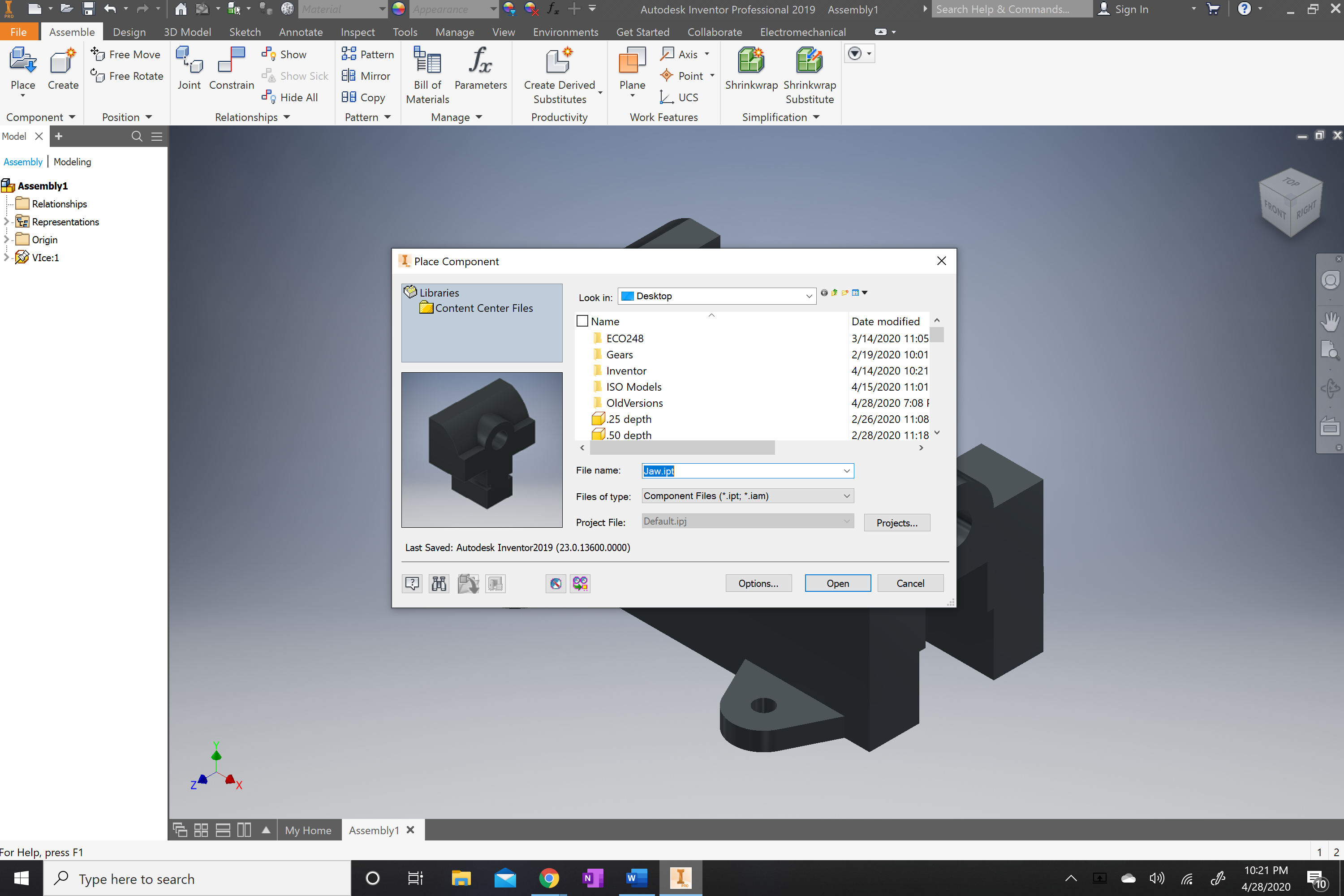
Once vice body is grounded you can now bring the remaining parts. The first part will be the jaw of the vice. You will repeat the process from steps 9 to 13 but the part will be the jaw. This part will not be grounded.
.png)
.png)
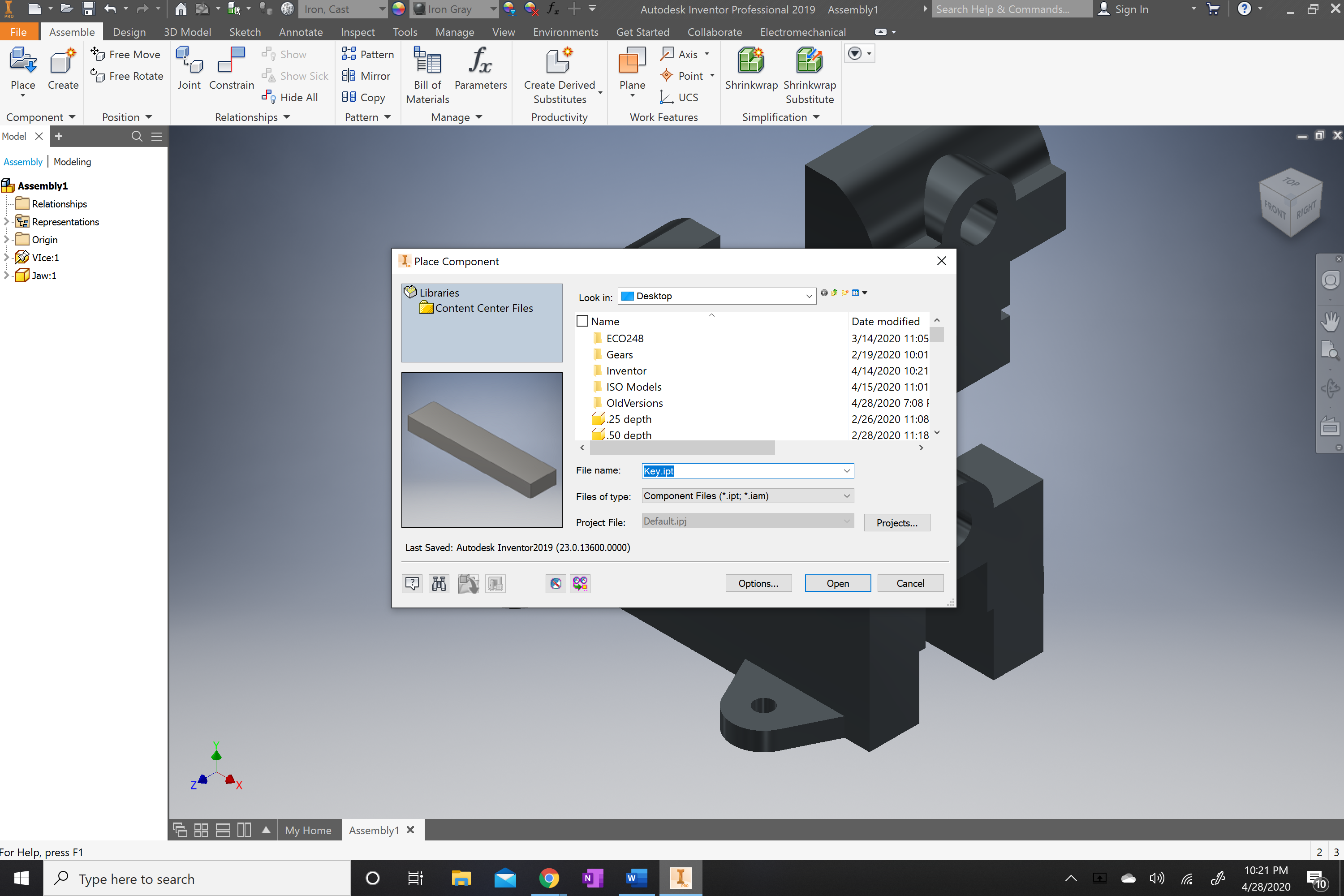
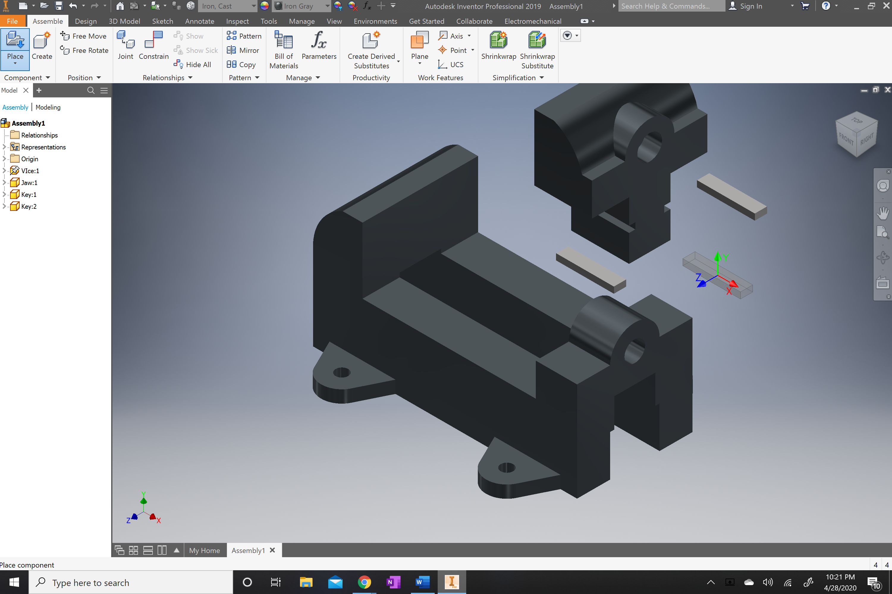
Once the jaw is in the work space you will next locate the key in the file folder and place two keys into the work space.
.png)
.png)
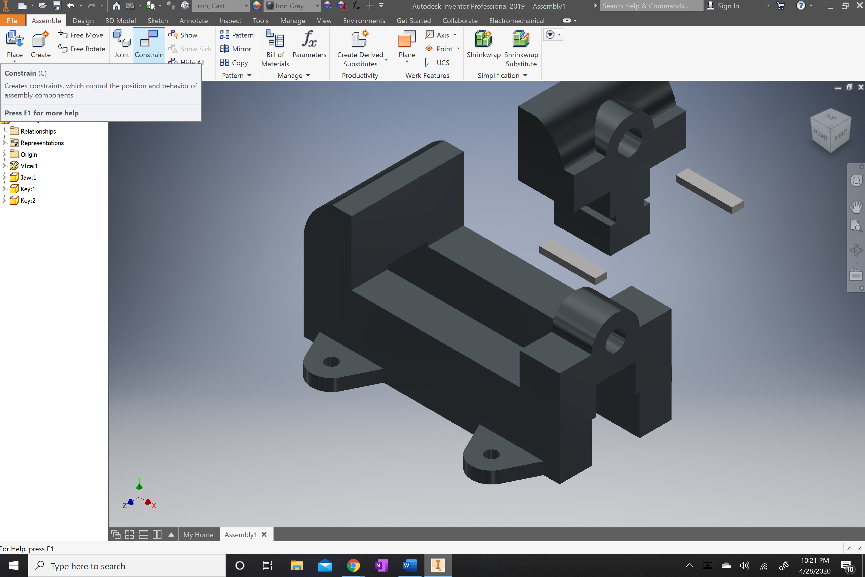
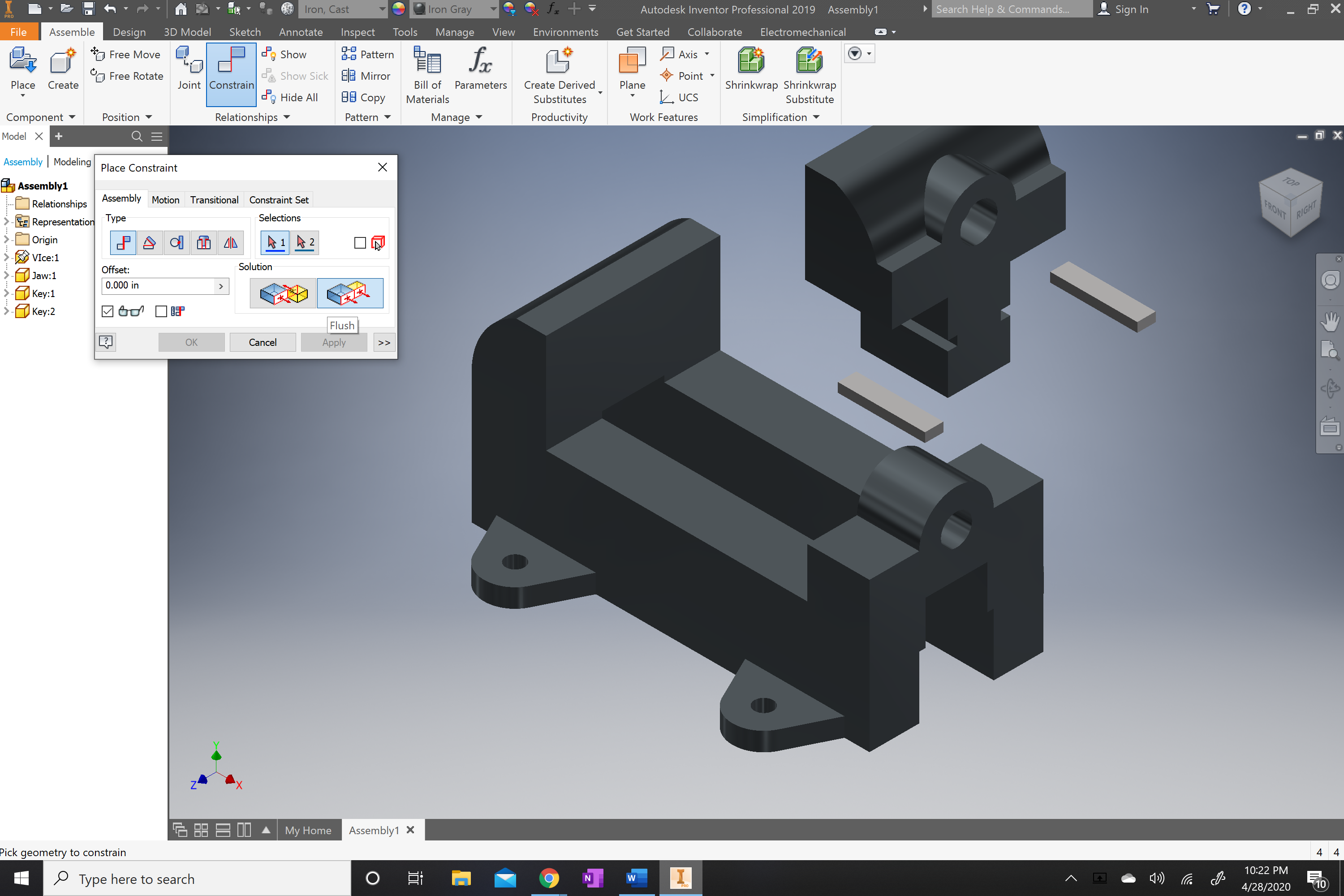
You will now locate the constrain command on the top portion of the tab. And select the right side of the key and the jaw using the flush and then mate on the front of the face of both.
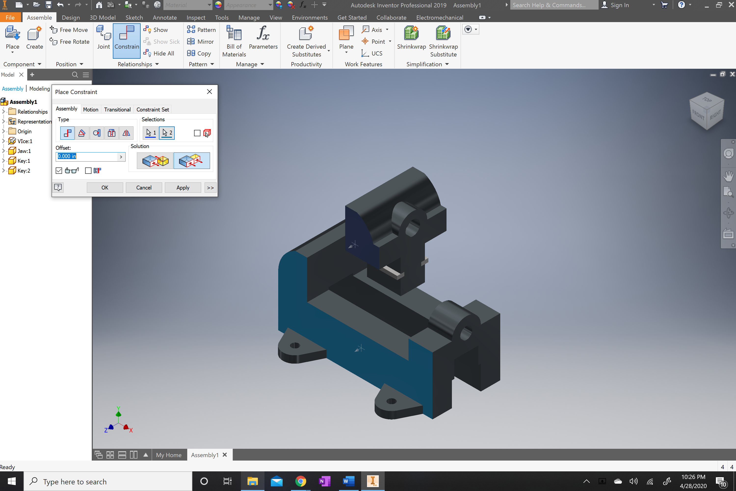
You will now locate the constrain once again to move the jaw to the vice body.
.png)
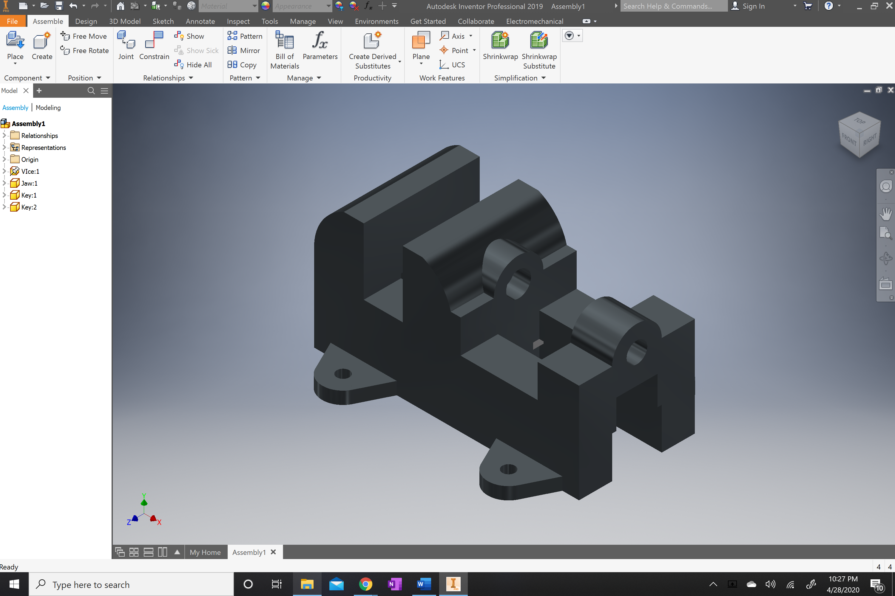
Once constrain is selected you will select the front face of the jaw and then select the front face of the vice body and then select apply. This will flush both faces. And they will not be able to move the parts side to side.
.png)
.png)
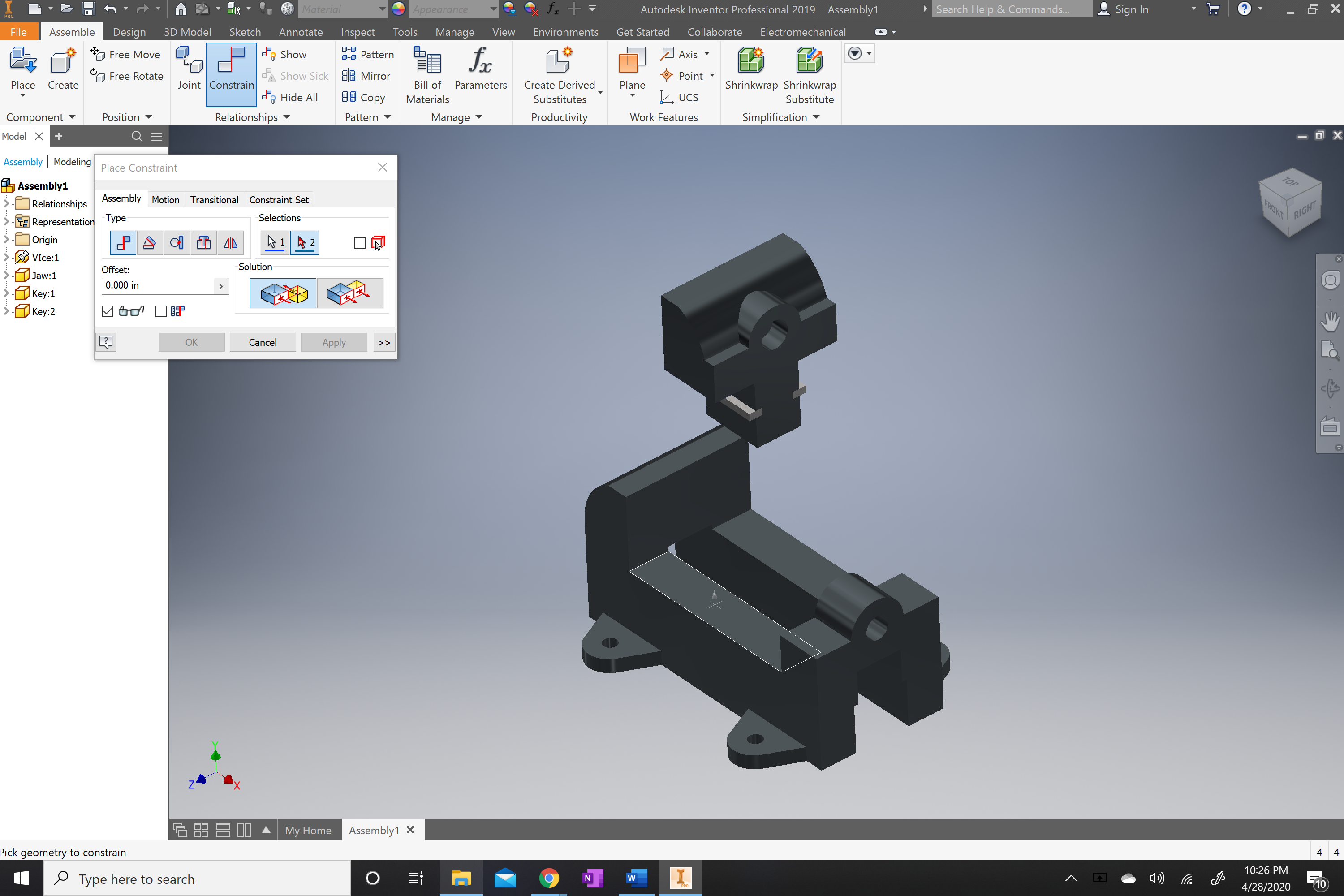
Repeat step 17 but this time you will select the mate option and then click on the bottom part of the jaw and also click the top part of the vice body. This will allow the objects to rest on each other.
.png)
.png)
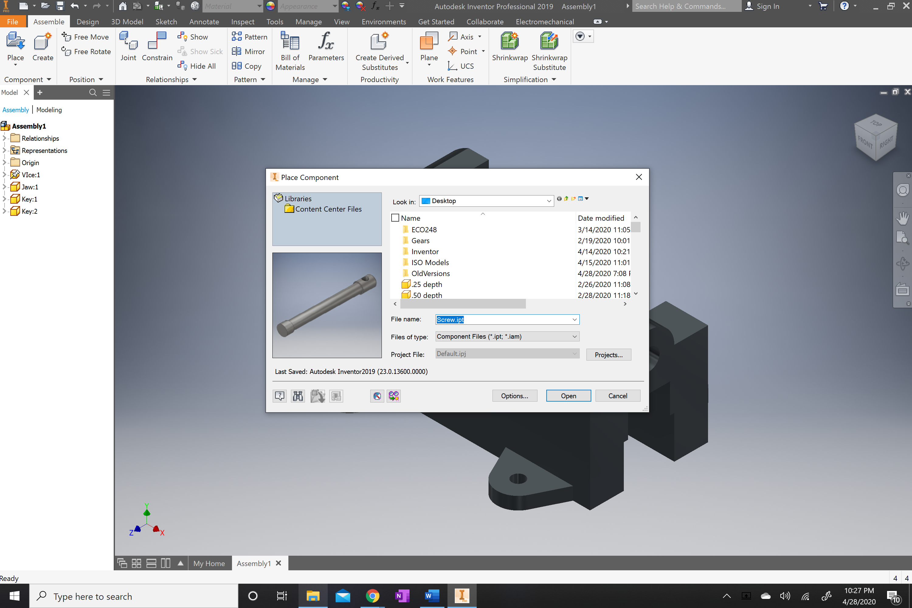
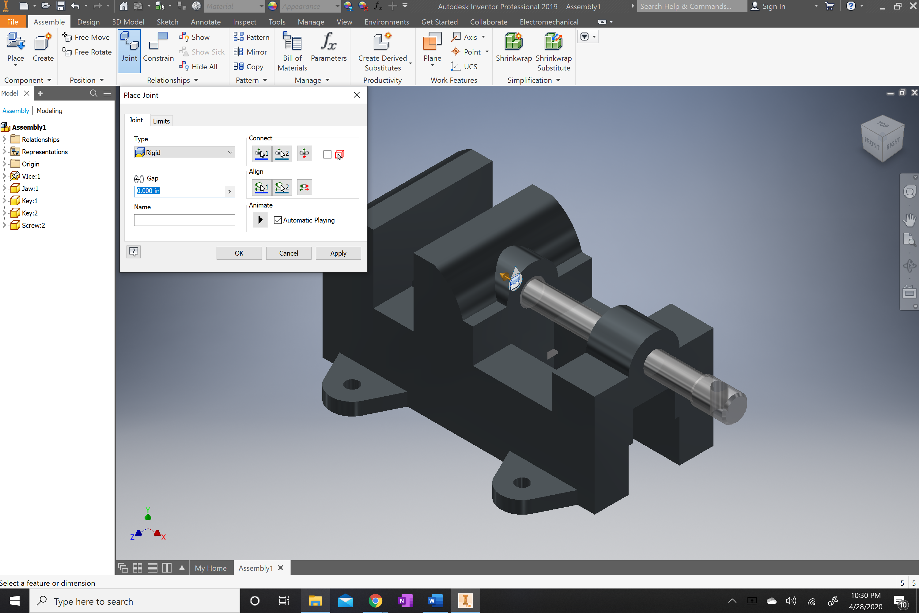
You will repeat step 9-13 but will select the screw. Place the screw in the space without grounding. Select the joint tab and click on the side without the hole of the screw and select the inner most face of the hole of the jaw. this will lock in in place.
.png)
.png)
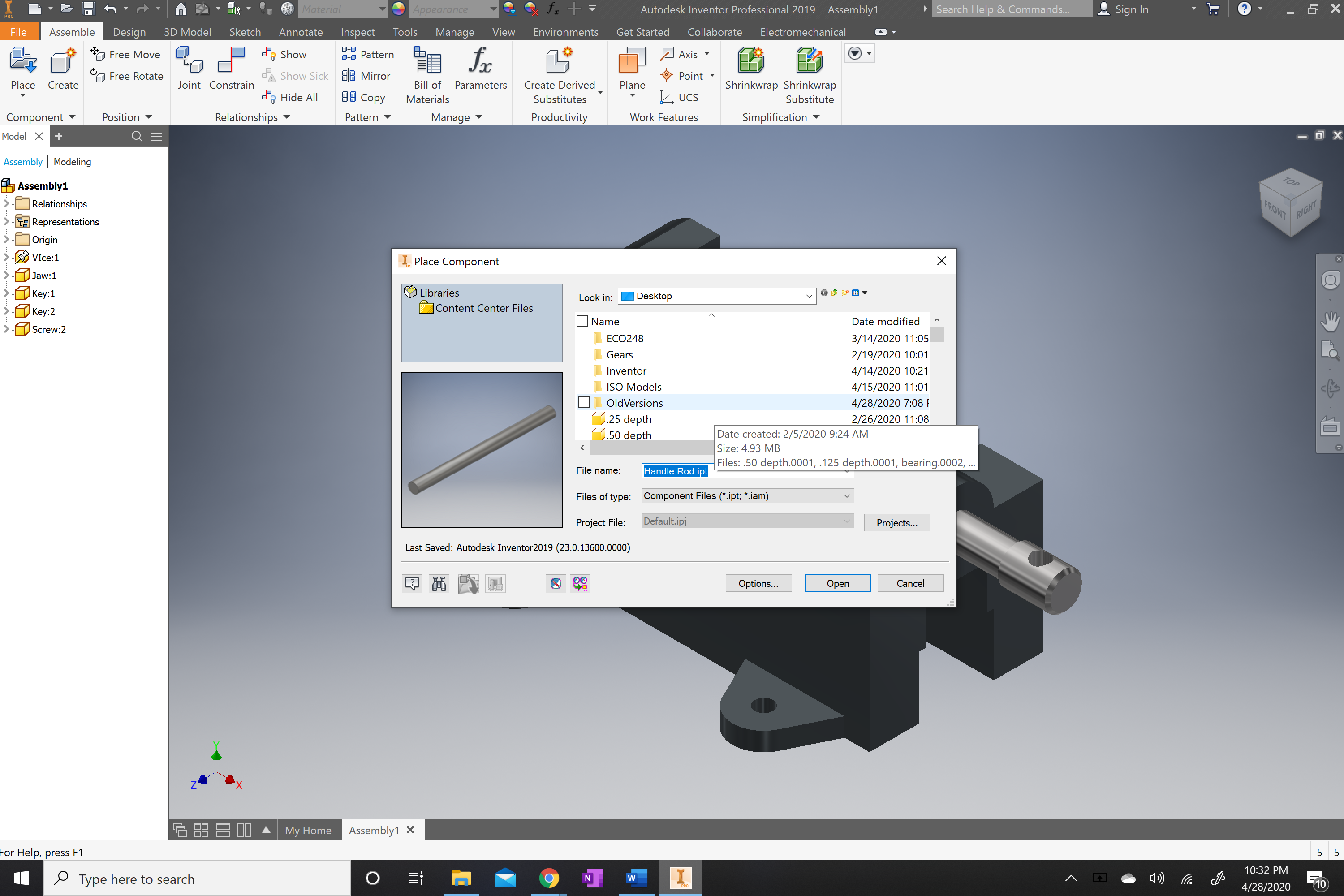
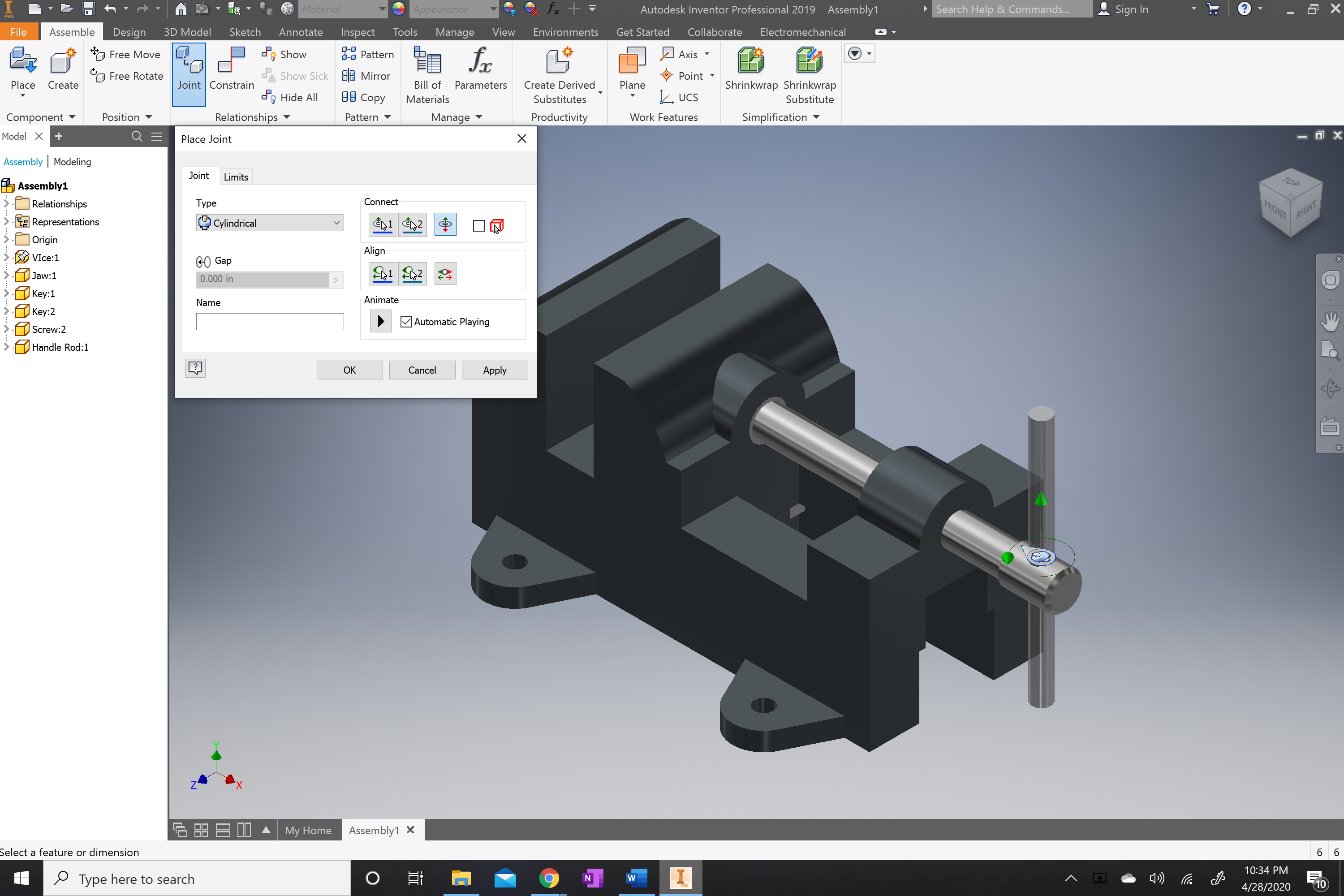
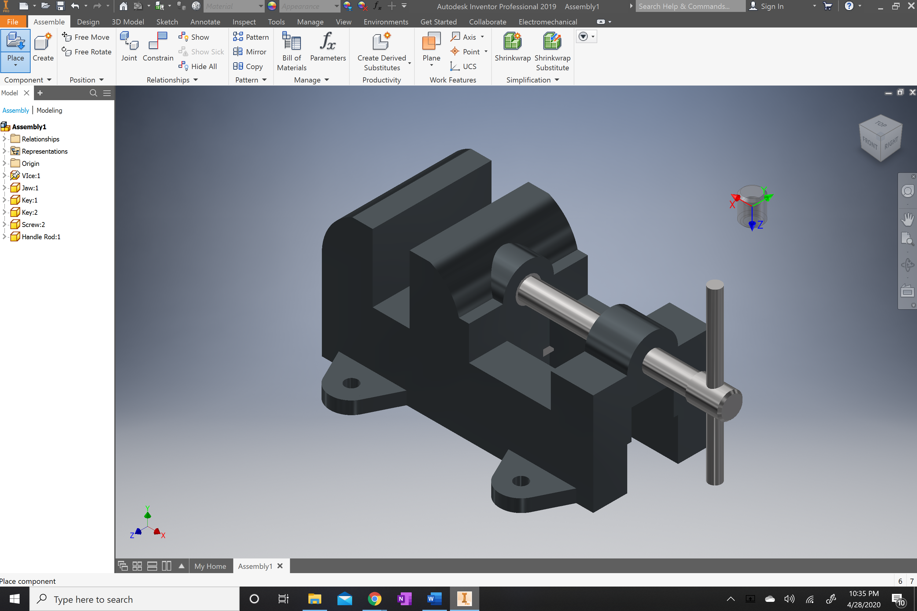
You will now place the handle rod into the work space and use the joint command once again selecting the middle of the rod and the top hole of the screw.
.png)
.png)
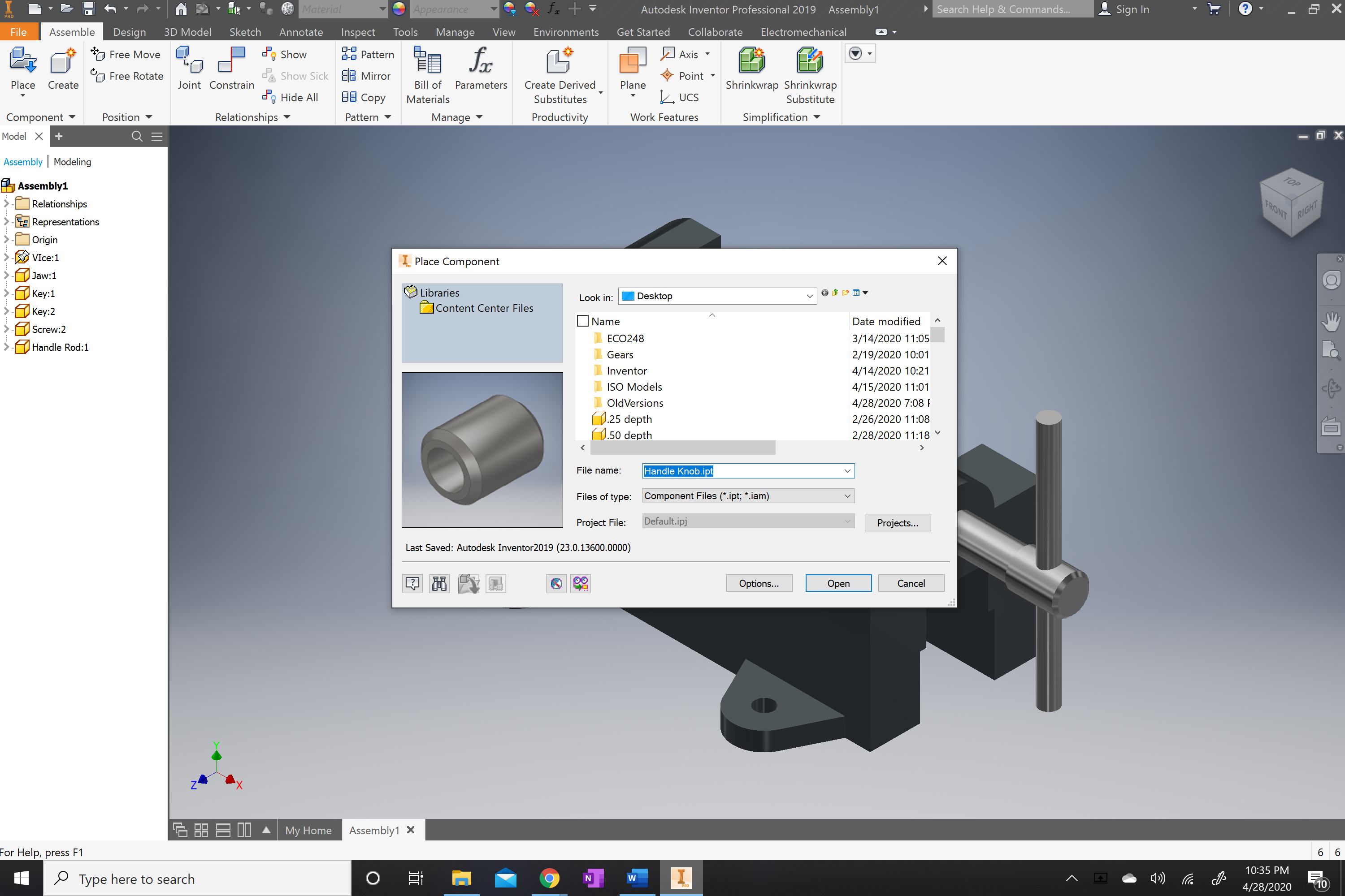
You will now select the place tab and find the handle knobs that go with the handle rod. You will place two in the work space.
.png)
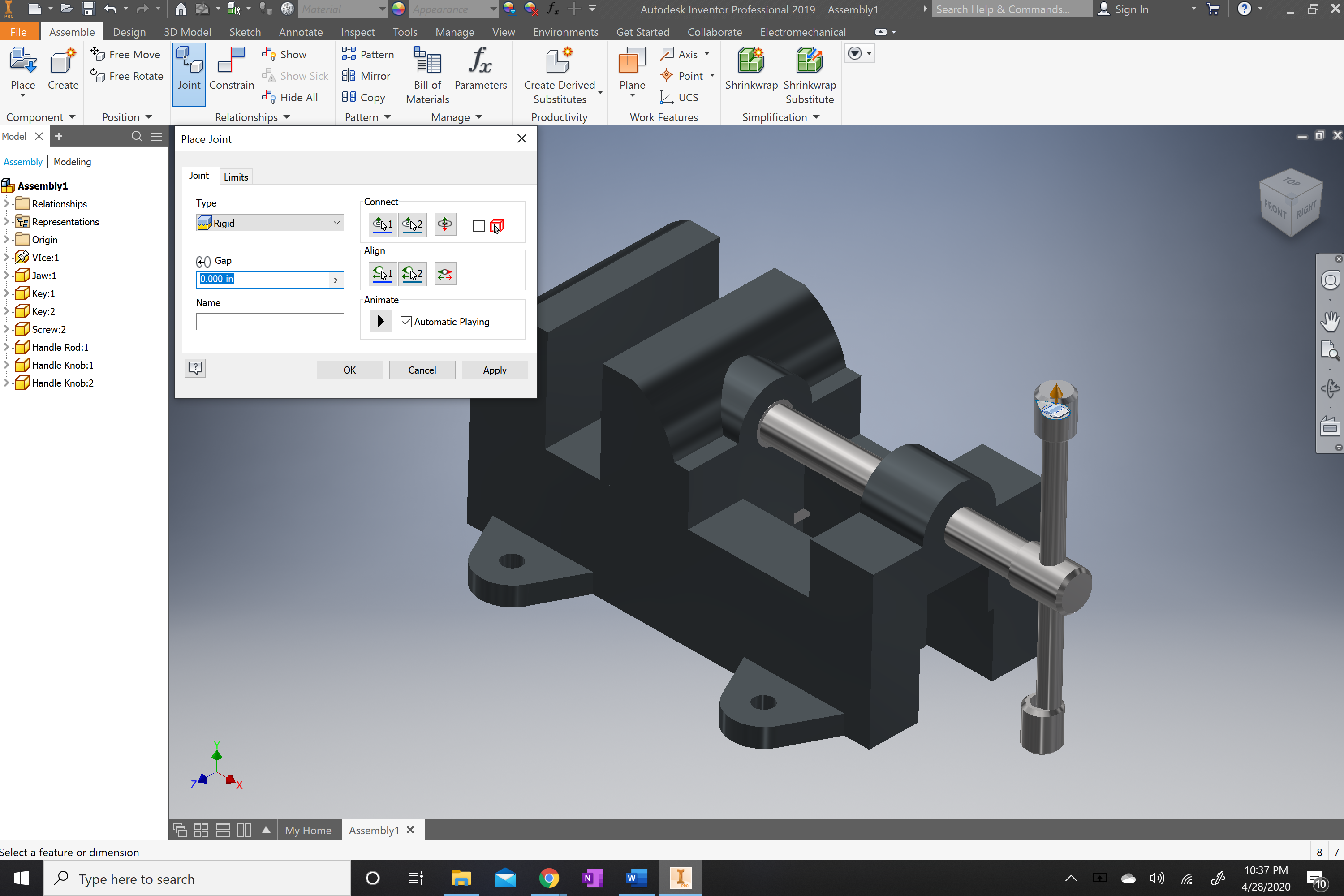
Next you will use the joint command to adjust the knobs correctly onto the handle rod.
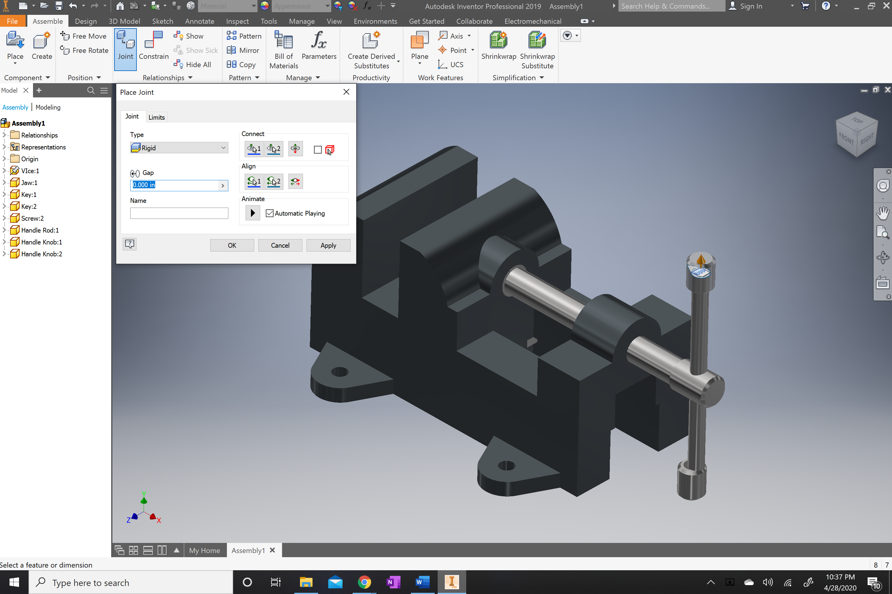
You will now locate the joint tab in the upper part of the screen. once located click on the inner part of the hole on the handle knob and then select the upper most part of the handle rod.
.png)
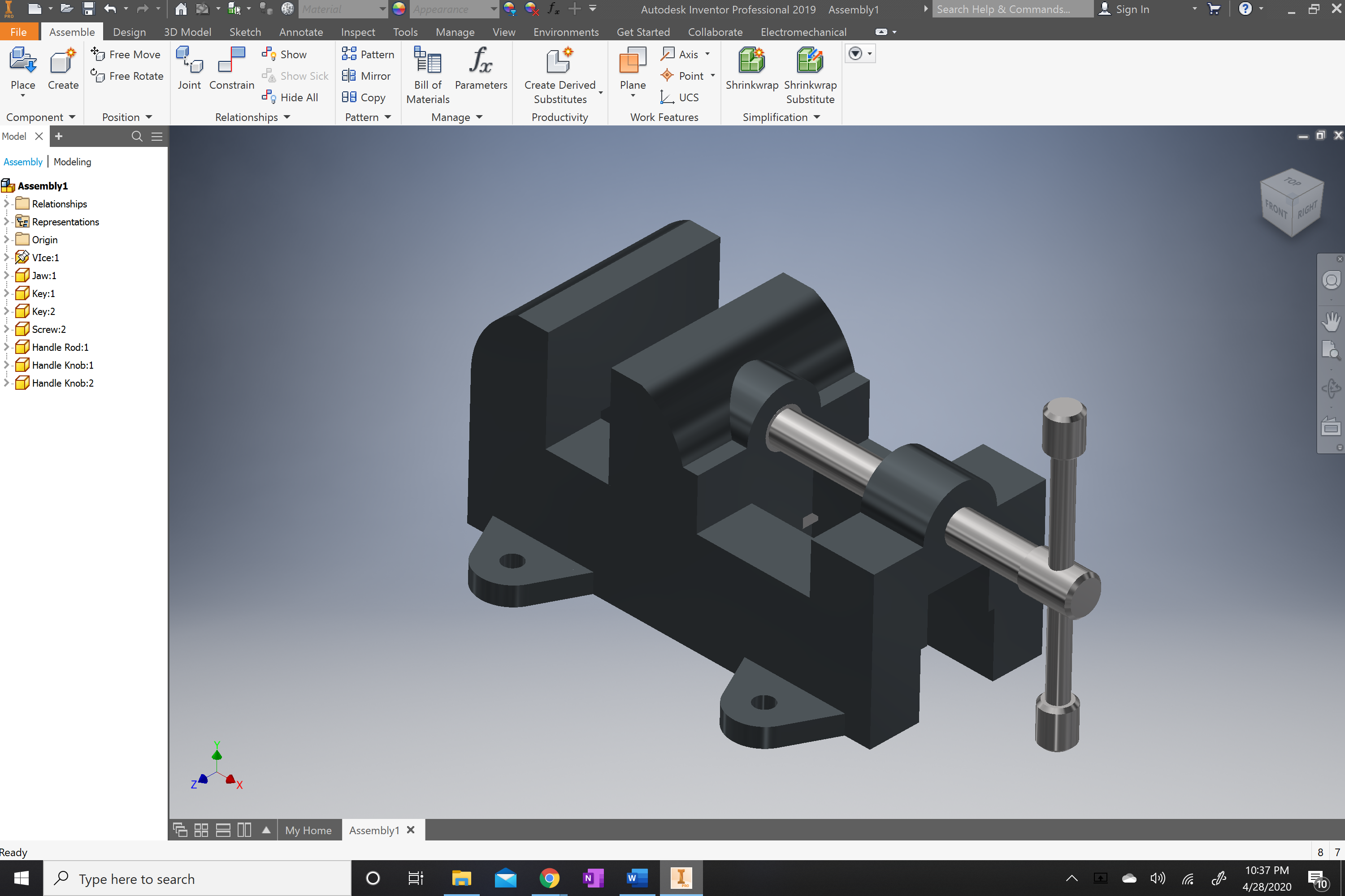
once you have done it for one of the handle knobs you will repeat the process with the bottom one.
.png)
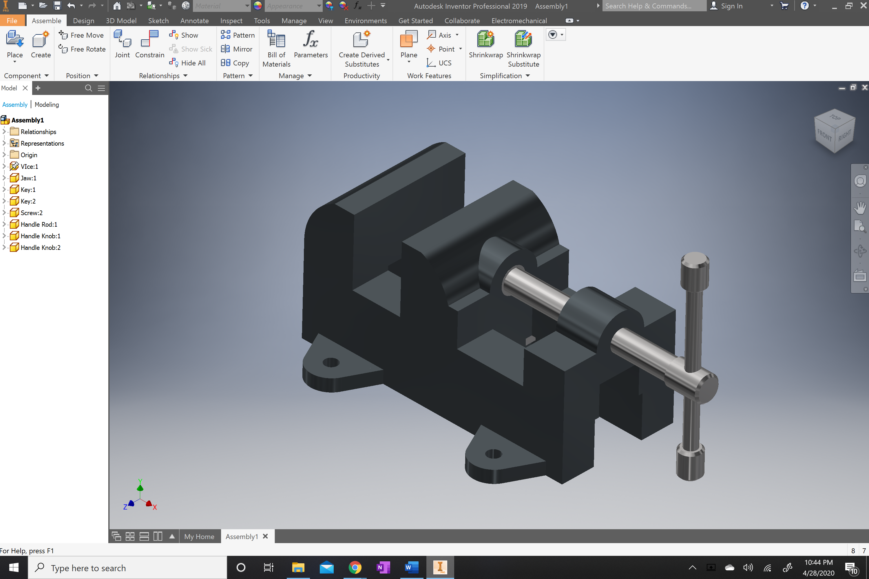
Once both are secured the handle rod will be able to move the screw and the jaw without moving any component that does not need to be moved.
The assembly should be complete at this step. But there are a couple more steps to completely finish the project.
.png)
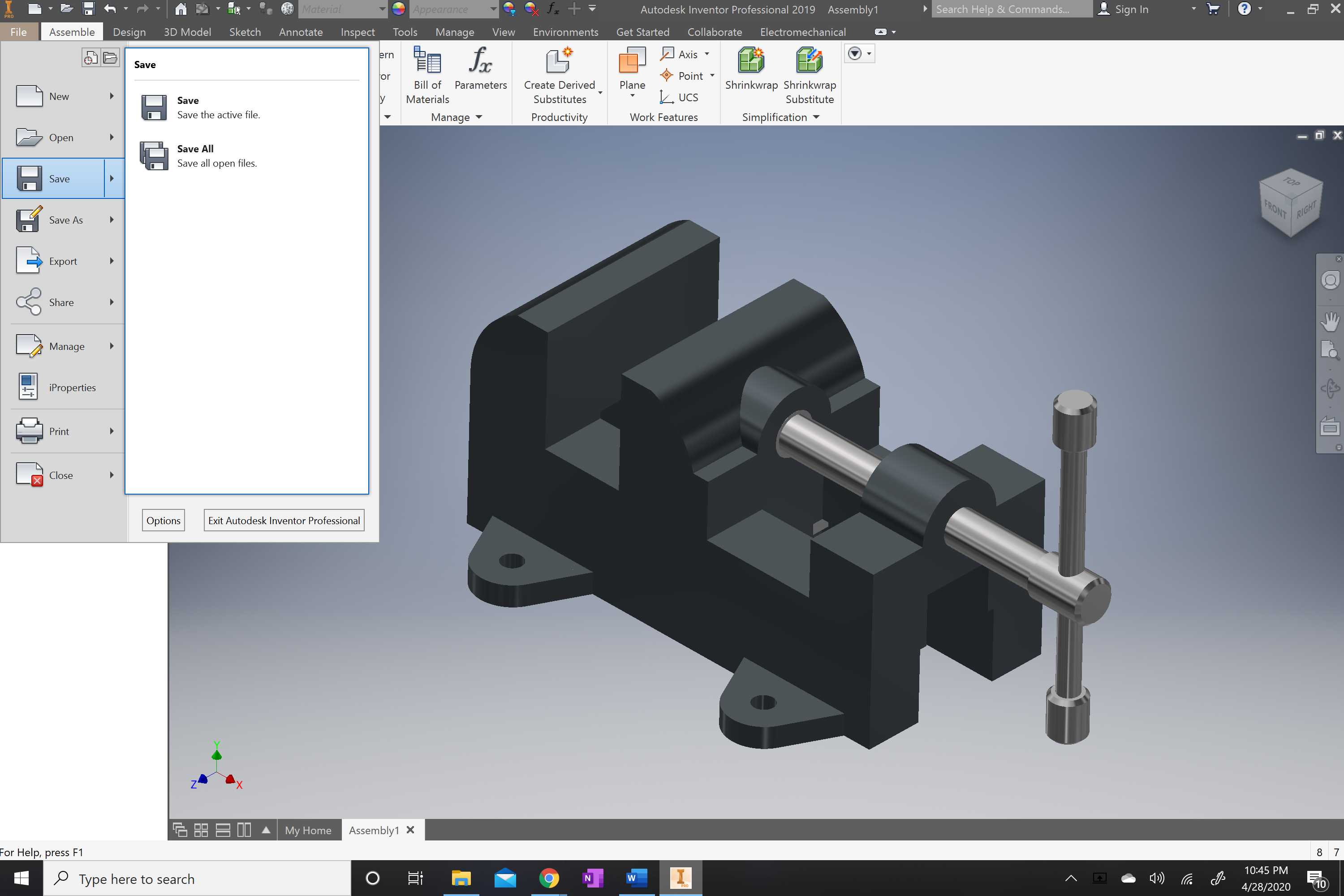
You will now look for the file tab. It should be in the top left corner.
You will select it and save the project as Vice Project.
.png)
You are now finished with the assembly.