The Snap!Mobile - Start Your Physical Computing Engines!
by MrYsLab in Circuits > Arduino
22265 Views, 40 Favorites, 0 Comments
The Snap!Mobile - Start Your Physical Computing Engines!

QUESTION
What do you get when you combine Snap!, the premier drag and drop programming language, with an off the shelf rover vehicle kit, an Arduino micro-controller and s2a_fm interface software?
ANSWER
A flexible and cost effective physical computing teaching platform.
For about $65.00 for the wired version, or $120.00 for the WiFi version, you and your students can assemble this prototype rover and use it as the foundation to learn about computer programming, physical computing, electronics and robotics. After completion of this project, additional sensors and actuators can be easily added.
You can also use this tutorial as a basis for less expensive and ambitious motor control projects.
INTRODUCTION
Finding a teaching platform for physical computing that is both reasonably priced and adaptable enough to meet the needs of students whose abilities and ages vary widely, seems to be an impossible task. That is the challenge that this project tackles head-on.
This prototype project not only finds a solution for the budget issues, but as we shall see, solves the flexibility issues as well. We keep the budget in check by using low cost, off the shelf hardware and open source, free of charge, software.
Solving the adaptability issues as it turns out, is really a Snap! The Snap! programming language that is. As you will see, once the hardware and software is in place, it will remain unchanged, with the variability needed to meet specific classroom needs confined to the Snap! programming environment. This helps to simplify the life of any classroom instructor teaching computing.
A WORD ABOUT SNAP! , ARDUINO, and s2a_fm
Snap!, is a free to use, visual, drag-and-drop programming language, that comes from the good folks at the University of California, Berkeley. Snap! really stands out among visual drag and drop languages. It's “build your own block feature” let's you create custom programming blocks that are accessible anywhere within a project. Custom blocks are created using the familiar standard block set provided with Snap!, so creating and extending programs is just a natural extension of what you already know. In addition, to quote the Snap! Reference Manual, “it also features first class lists, first class procedures, and continuations. These added capabilities make it suitable for a serious introduction to computer science for high school or college students.” This allows the programming environment to be tailored for students of varying ages and abilities. Best of all, physical devices can be controlled and monitored via Snap! without having to learn any additional programming languages. The interface program called s2a_fm, seamlessly connects an Arduino micro-controller to Snap!. It uses the Firmata hardware abstraction protocol to control the Arduino.
In the pages to come, we will build the initial stages of the Snap!Mobile, a WiFi controlled roving vehicle. We start with a wired version of this project. We then quickly move on to a WiFi version with a minimum of effort (thanks to Snap!). We include a short discussion of the software components used in this project and a look at how the custom blocks were crafted for the Snap!Mobile and how they can be tailored for use by students of any age or ability level.
After reading this tutorial you should be able to easily add sensors and other actuators to the Snap!Mobile for added functionality and learning opportunities.
Hardware and Software Needed


You will need the following: (potential vendors are provided within the links. Check the web for current best prices)
Vehicle Hardware
Tamiya 70108 Tracked Vehicle Chasis
Tamiya 70168 Double Gearbox
Pololu DRV8835 Dual Motor Driver Carrier
Polulu 5V Step/Up Down Voltage Regulator (For WiFi version)
Radio Shack AA Battery Holder
Arduino Yun (for WiFi Version) or Arduino Uno (or UNO clone) , Leonardo or 2650 R3 (for wired version).
Miscellaneous Hardware
Micro SD card (4 GB is sufficient - for WiFi version)
Wireless Breadboard
Jumper Wires
Open Source Software
Python 2.7 or greater (version 2 only, not version 3)
Arduino 1.5.5 IDE
pySerial Python Library
PyMata Firmata Interface Library
s2a_fm Snap!/Scratch Hardware Extension
Assemble the Vehicle Chassis and the Gearbox
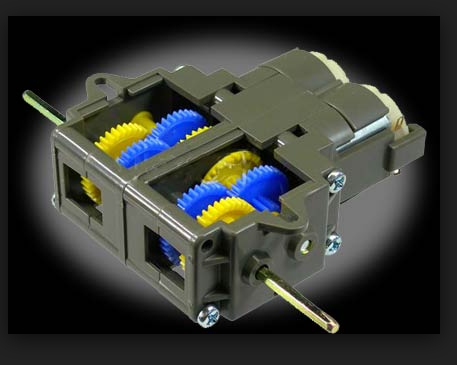
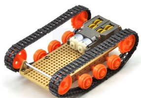
Follow the instructions supplied with the chassis kit. Set aside the single motor and gear box supplied with the chassis kit since we will be using the dual gear box and dual motors instead.
After assembling the chassis, assemble the dual gearbox next. When complete, solder wires to the motors. Mount the dual gearbox to the chassis and then attach the tank tracks as per instructions.
The instructions for both the chassis and dual gear box consist of a set of illustrations. Familiarize yourself with the instructions before starting assembly and take your time assembling. Assembly is straight forward, but it will take patience, so do not rush it.
It took me about 3 hours to slowly and carefully assemble the two kits.
NOTE: The gear ratio I chose to use for the dual gear box was 114.7:1. Feel free to select any gear ratio that meets your needs.
Download and Install the Software for Wired Operation

- Using the links provided in Step 1 download and install Python 2.7 (or greater)
- Download and install the Arduino 1.5.5 Beta (or greater) IDE
- Download pySerial, PyMata and s2a_fm.
- Create a new directory and extract (unzip) all three Python packages into the new directory .
- Open a command window and "cd" to the newly created directory containing the Python packages.
Installing the Python Packages
NOTE: The following steps may require administrative privileges to complete.
With Python 2 installed, install pySerial by cd'ing into the pySerial 2.x directory and entering the following command:
python setup.py install
Now cd into the PyMata-master directory and type:
python setup.py install
And finally cd to the s2a_fm-master directory. Make sure that the the file called s2a_fm.py has executable permissions.
We will start the s2a_fm program in a later step.
Upload Standard Firmata to the Arduino
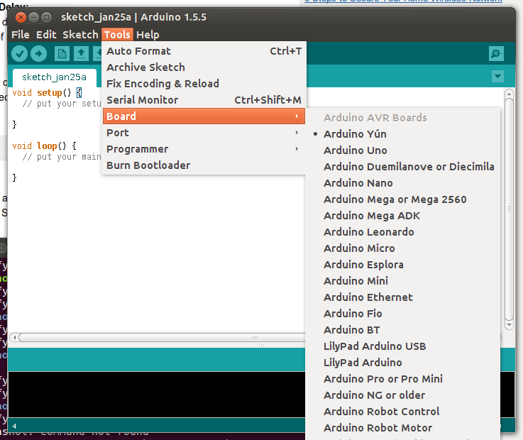
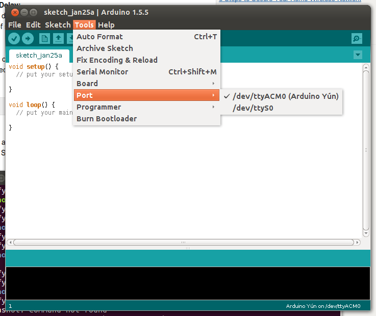
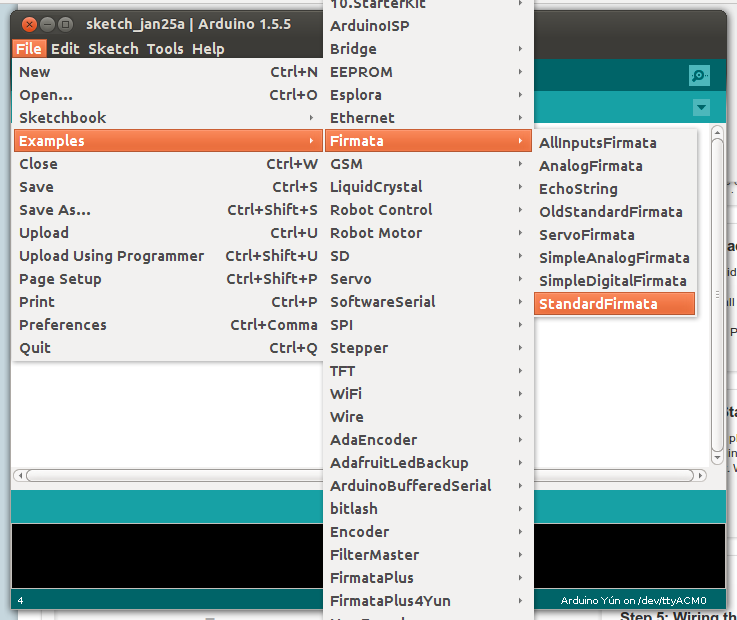
Using a USB cable, plug your Arduino into your PC.
Next, open the Arduino IDE and select your Arduino board type.
Then select the port. Write down the port ID, since we will need that later.
Now from the File menu on the IDE, select Examples/Firmata/Standard Firmata and upload the file to the Arduino.
After installing StandardFirmata, reset the board (you can remove the USB cable and plug it back in), the LED Labeled L13 (on the Yun) or L (on the other boards) should flash a few times and then extinguish. StandardFiramata flashes its version number.
Start S2a_fm, Snap! and Test Everything With a Blink Script
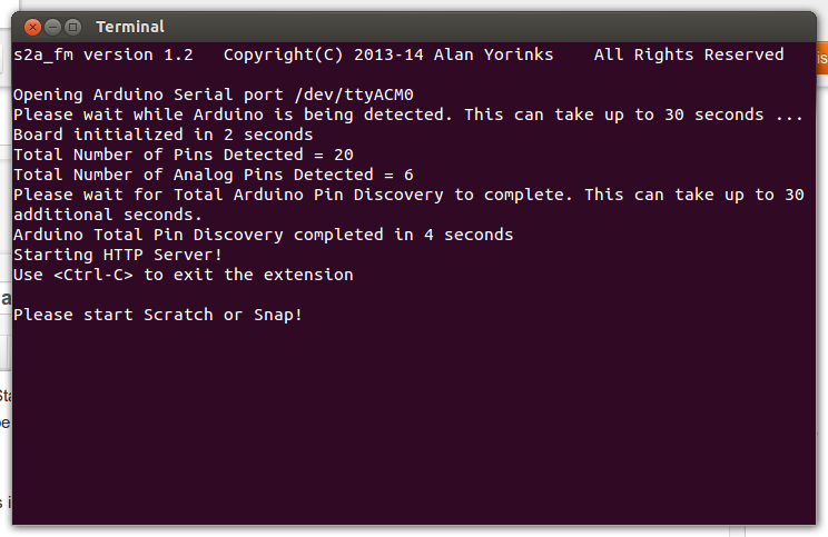
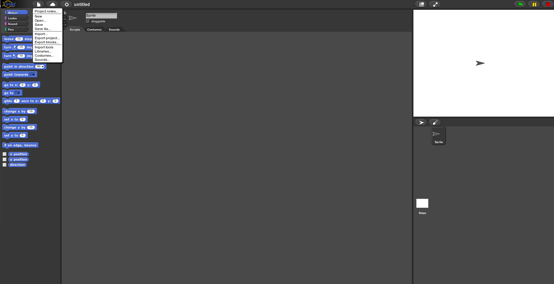
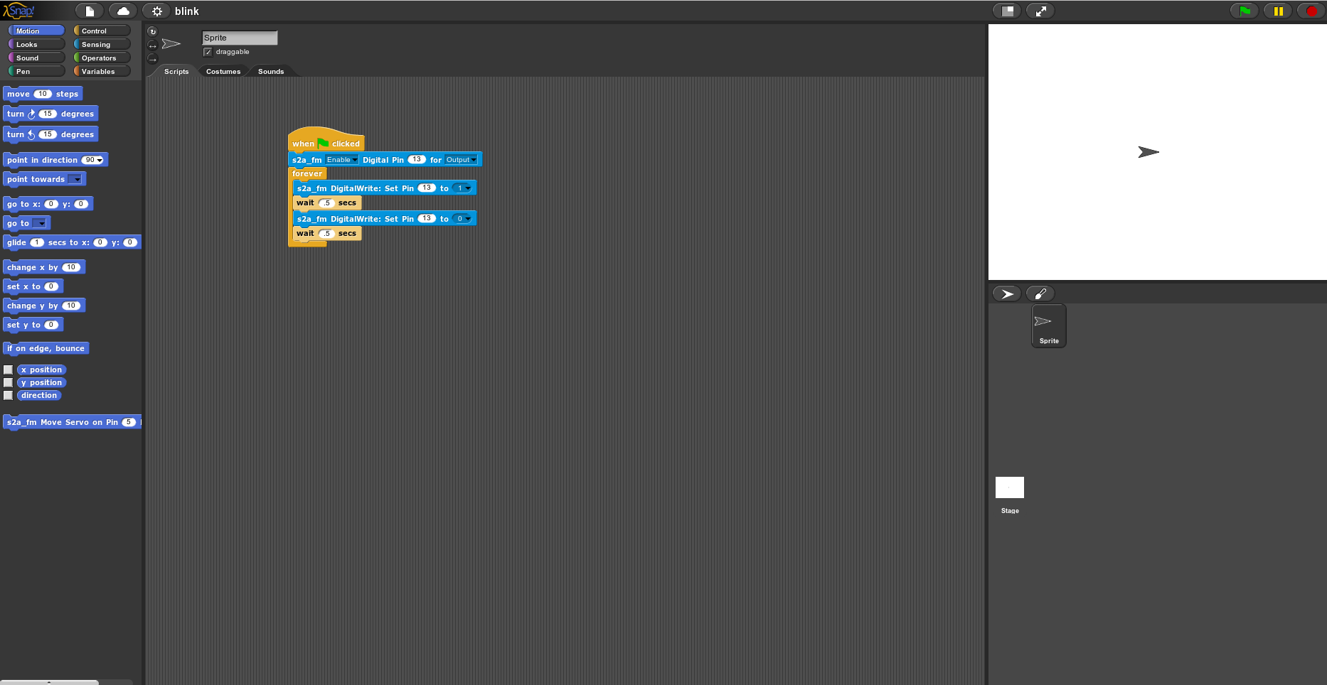
After uploading Standard Firmata to the Arduino, go to the command window and CD to the s2a_fm-master directory and type:
./s2a_fm.py
If everything was installed properly, you should see something like the screenshot above in your console.
Now open Snap! by clicking on the link. Let's test the entire setup by using a Snap! script to blink the LED connected to Pin 13 onthe Arduino. Select the File icon at the top left of Snap!, and then select Import... This will bring up a file chooser dialog box. Go to the s2a_fm-master directory on your computer and then go to the Snap!Files directory and choose blink.xml
The blink script should appear in the editor ready to run. Click on the Green Flag in the upper right of the Snap! editor, and the hardwired LED attached to pin 13 on the Arduino should start to blink.
If you see the LED blinking, you have successfully loaded and tested the software.
Building the Prototype - Wiring Up the Arduino, the DRV-8835 Dual Motor Driver and Motors
Assembling the Dual Motor Driver Carrier
- Solder the headers supplied with the Pololu DRV8835 Dual Motor Driver Carrier to the carrier.
- Plug the Motor Driver into a breadboard.
Connecting The Arduino to The DRV8835
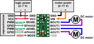
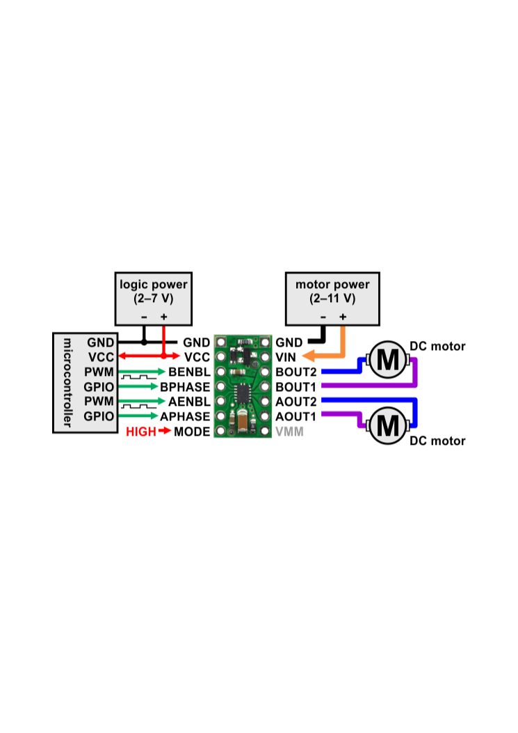
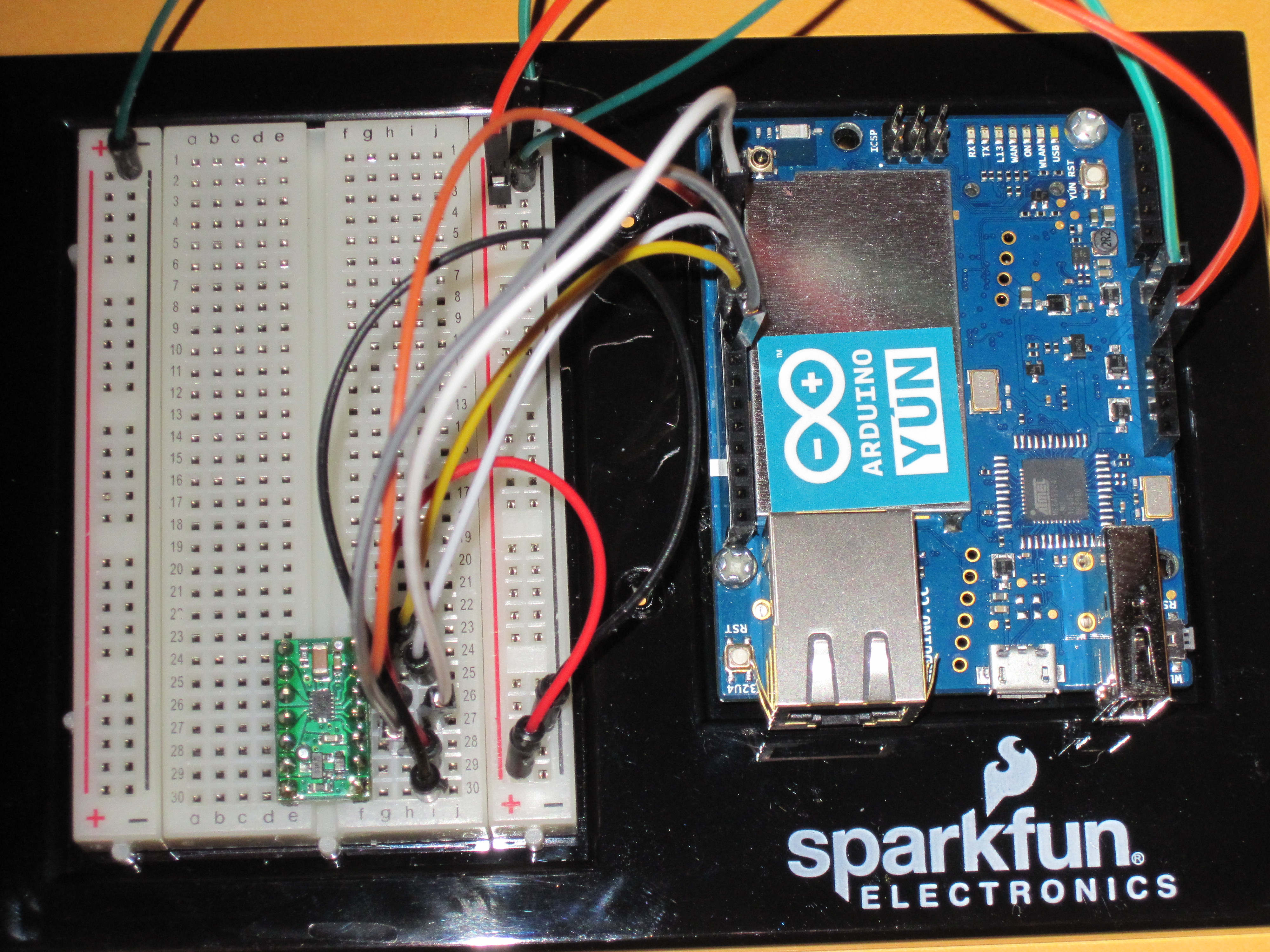
Using the diagram in the first screen shot, the left hand side pins of the DRV8835 are connected to the Arduino.
The DRV8835 controls 2 motors. there are 2 control pins for each motor.
The "xENBL" pins control the speed of the motor. These pins must be connected to a PWM (Pulse Width Modulation) pin on the Arduino.
- Connect AENBL to Arduino digital pin 5.
- Connect BENBL to Arduino digital pin 3.
The xPHASE pins control the motor direction.
- Connect APHASE to Arduino digital pin 7.
- Connect BPHASE to Arduino digital pin 4.
The MODE pin controls the operational mode of the DRV8835.
Connect MODE to Arduino digital pin 8.
Connecting Power to the Arduino Side of the DRV8835
- Connect the GND (ground) to the Arduino ground (Either GND pins on the Arduino Power connector).
- Connect VCC to the Arduino 5V power pin.
Connecting the Motors to the DRV8835
Looking at the diagram on this page, the right hand side pins of the DRV8835 are connected to the motors.
- Connect the Upper wire from the first motor (pick either) to AOUT1.
- Connect the Lower wire from the first motor to AOUT2.
- Connect the Upper wire from the second motor to BOUT1.
- Connect the Lower wire from the second motor to BOUT2.
Connecting Power to the Motor Side of the 8835
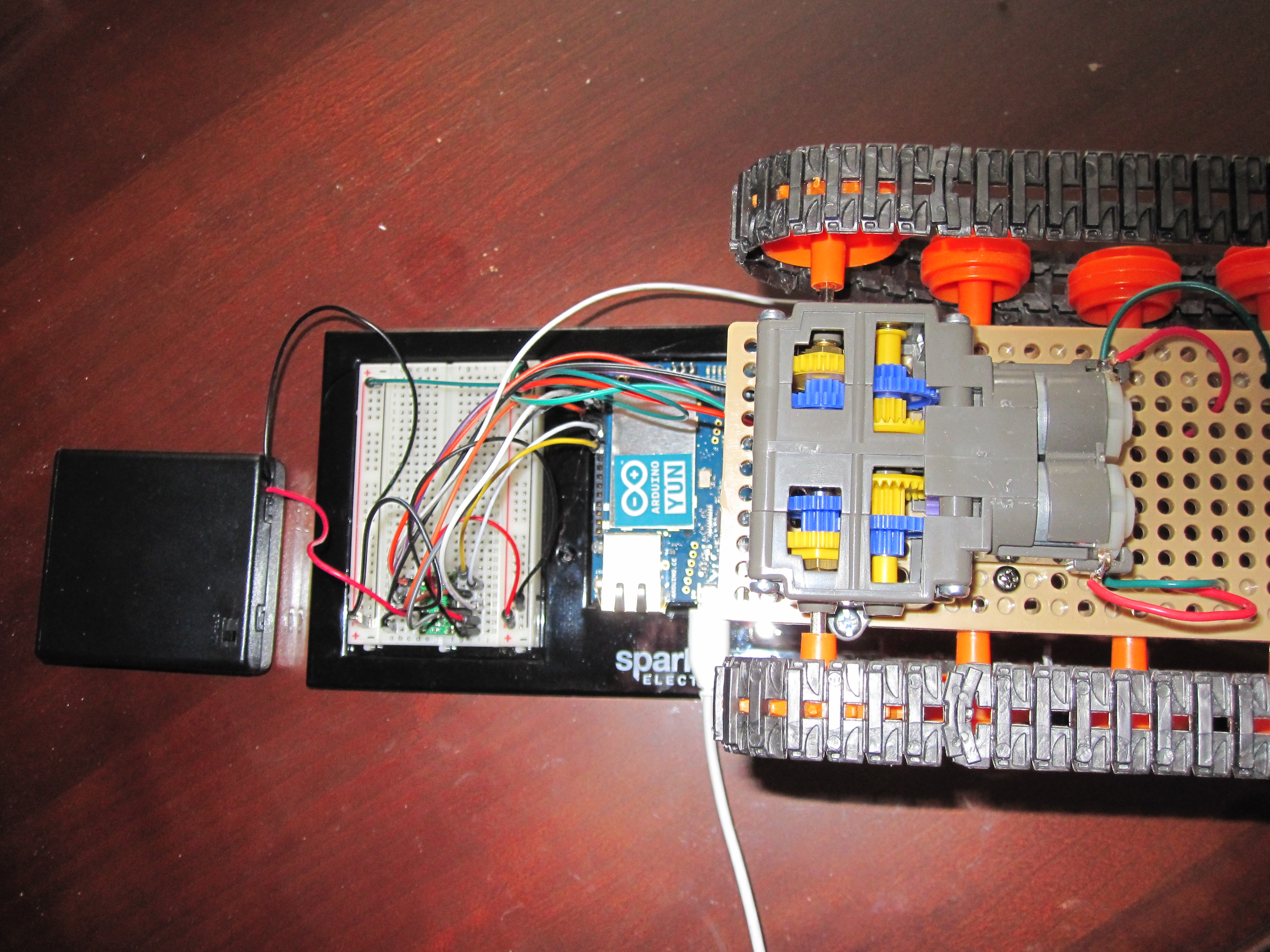
- Place 4 AA batteries in the battery holder.
- Connect the positive lead to VIN
- Connect the grounds from the Arduino and Motor sides together.
Testing the Motors Using Snap! in a Wired Configuration
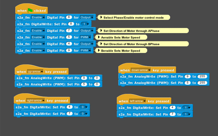
If s2a_fm is not currently executing and/or Snap! is not already open, start these programs as described in Step 5, but this time, instead of importing blink.xml into Snap!, import wiredMotorTest.xml, located in the
s2a_fm-master/Snap!Files/Snap!Mobile directory.
Make sure that power to the motors has been applied. Click on the "Green Flag" in Snap! to initialize the Arduino, and then use the up and down arrow keys to run both motors at full speed in either the forward or reverse direction. To stop the motors, press the space bar.
A Quick Look at the Snap!Mobile Softare Components

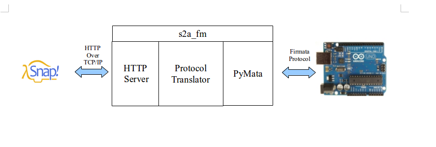
When Snap! executes one of the custom s2a_fm blocks, an HTTP "GET" request, is sent to a web server that's running within s2a_fm. The HTTP request is then translated by s2a_fm into an Arduino Firmata protocol message using the PyMata library. When the Arduino wishes to send information back to Snap! (for example, updated sensor or status data), it sends a Firmata message to s2a_fm through PyMata, and s2a_fm translates the Firamata message to an HTTP response message that is then in turn, relayed to Snap!.
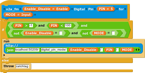
An important thing to note is that the s2a_fm execution blocks were all created using the Snap! "Make a Block" feature. This feature allowed the easy creation of custom blocks that match the protocol requirements of s2a_fm. The "Make a Block" feature is so flexible that it allows us to direct the HTTP request to a custom IP address. This is an important distinction, because it will allow us to adapt our script to go from wired control to wireless with almost no effort, as we shall see in a later step.
The Magic of Snap! - the Flexibility and Genius of the Custom Block
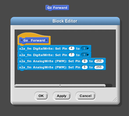

We've already touched upon how the Snap! "Make a Block" feature allowed us to create custom s2a_fm command and response protocol blocks, but here is where I think the real magic comes in. Not only can we create custom command and reporter blocks by reusing standard and custom blocks, but we can reuse existing scripts and incorporate them into the new blocks as well!
This gives an instructor full control of how much detail and complexity to expose. By taking an existing set of blocks that display full functionality and complexity, an instructor can easily and quickly repackage that functionality set into a simpler view, hiding any unnecessary details. Essentially, Snap! allows us to tailor the language to meet the specific needs of students.
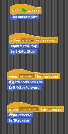
To illustrate, let's look at the screen shots above. The first screen shot depicts a set of scripts for basic motor control using the s2a_fm blocks. This might be an appropriate level of detail for a class of advanced students exploring micro-controllers, but not for a class of beginning students. In the second screen shot, we see the "Make a Block" definition for a higher level "Go Forward" block. It was created simply by cutting and pasting some of the s2a_fm blocks into the new block. A complete set of simplified functionality blocks is shown in the third screen shot. All of the simplified blocks were created from those in the first screen shot by simply cutting and pasting. The entire task of converting from the first script to the simplified block set took about 10 minutes.
Using Snap! to Easily Go From Wired to Wireless

In the wired configuration of this project, all the Python code (Python, Pyserial, PyMata and s2a_fm) executes on a PC. Communication between Snap! and s2a_fm is performed over the "network" using the localhost IP address. Communication between s2a_fm/PyMata and the Arduino for the wired configuration is performed over a wired USB serial link between the PC and the Arduino.
For the wireless configuration, the PC is replaced with the Linux processor running on the Arudino Yun. In the wireless configuration, communication between Snap! and s2a_fm is performed using the IP address of the Yun.
To go from wired to wireless do the following:
1. Provide a 5 volt regulated source of battery power to the Arduino Yun.
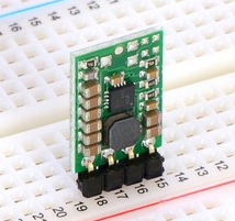
The Yun requires a regulated 5 volt power supply to assure its proper operation. To make this project truly wireless we are going to use a battery supply. The voltage of a battery supply can vary widely, especially as the battery discharges. To assure we have a constant 5 volts we are going to use a Pololu 5V Step-Up/Step-Down Voltage Regulator S7V8F5. We will also add the suggested 33 μF capacitor to protect the circuitry of the regulator as suggested on the product page.
2. Upload a special version of StandardFirmata to the Yun.
The special sketch may be found in the s2a_fm-master/Snap!Files/Snap!Mobile/StandardFirmataYun directory.
3. Find the IP address of the Yun.
Using a web browser, go to arduino.local to see the Yun's IP address. (Visit the Arduino page for the Yun for further information). Write this address down for later use.
4. Copy the s2a_fm-master/Snap!Files/Snap!Mobile/arduino directory and all of its contents to a USB thumb drive or SD card. Using your favorite editor, open arduino/scratch_http_server.py and change the IP address located in the start_server class to match the address you wrote down in step 3. (See code sample above). Save the file.
5. Plug the thumb drive or SD card into the Yun, power the Yun and wait for a minute or so for the board to boot up.
Log into the Yun using the following command:
ssh root@STEP_3_IP_ADDRESS
For example, if your Yun's IP address is 192.168.1.155, the command would be
ssh root@192.168.1.155
If you set up a password for the Yun, you will be prompted for it.
6. CD to your USB thumb drive or SD card, then CD to the arduino directory and type:
python ./s2a_fm.py
7. The last thing we need to do is to modify the Snap! .xml script to use the IP address of the Yun. Let's modify the blink script to run over WiFi. Copy blink.xml located in the Snap!Files directory. Using your favorite text editor, globally search and replace the file for localhost and replace with the Yun IP address (step 3). Save the file with a new name, such as blink_yun.xml.
8. Start Snap! on your PC, import blink_yun.xml and execute the script by clicking on the Green Flag.
Congratulations! Snap! is now controlling the Arduino via WiFi.
NOTE: Steps 1 through 7 only need to be done this once. The only operation you will need to do to run an existing Snap! script is to replace "localhost" with the Yun IP address (step 7) and then run that script.
What's Next?
We are at the end of this article and hope you learned a little about crafting your own physical computing teaching vehicle.
Any questions or suggestions are always welcome.
What's next for Mr Y's Lab?
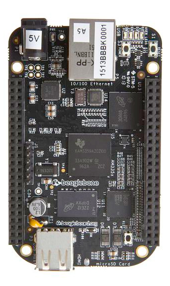
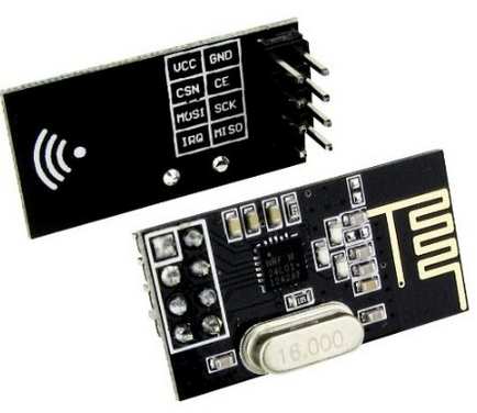
The screenshots above are for the BeagleBone Black and nRF24L01+ modules. Wonder what we can do with those?