The Light Clock (IoT)
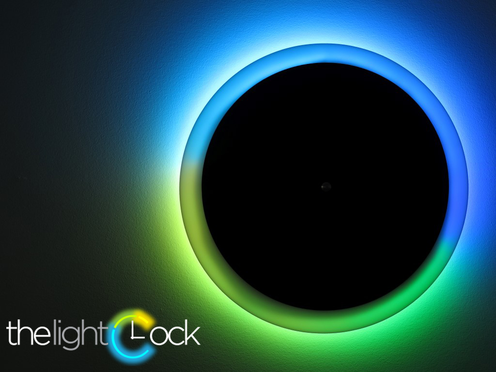
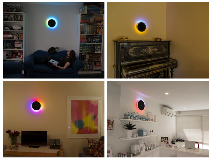

Welcome to The Light Clock, part art-piece, part timepiece, it's a modern take on the classic analogue clock. Where a traditional clock face uses hands to tell the time, The Light Clock turns your whole wall into a timepiece through a striking display of coloured light. You have the power to choose from millions of colours, allowing you to perfectly complement your existing décor, or simply to match your mood.
NEW!! We're offering pre-orders of "The Light Clock Kit" Which contains all the electronics and LEDs required to build the light clock with no breadboard or soldering. Make the body, add power and you're done!
We've also just had a successful kickstarter campaign and if you don't want to build your own you can now pre-order the clock here!
How to Tell the Time on the Light Clock?
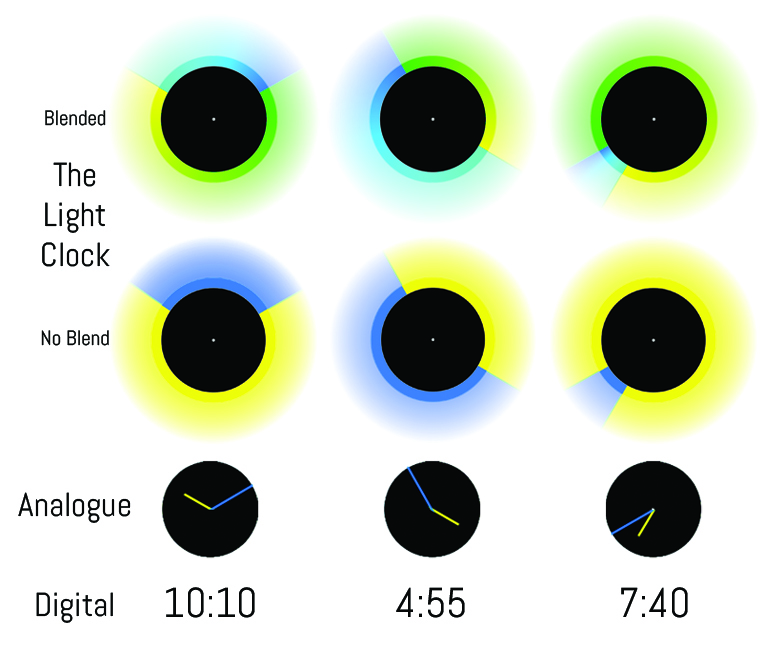
To create the hour and minute hands, The Light Clock projects light in two different colours. At first glance this might seem complicated, but very quickly you’ll notice that you can read it with ease.
In this example we’ve used yellow light as the hour hand, and blue light as the minute hand. Comparing each Light Clock with the corresponding traditional displays, you can see how each colour comes to an edge where a hand would normally be. Click for an animated example.
Parts and Tools

What you need is a
· Power Drill
Bigger tools required (shapeways is a good alternative if you don’t have these tools)
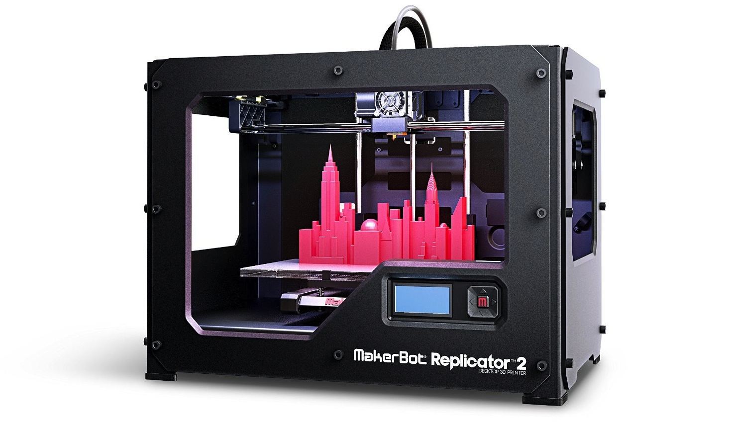
· 3D printer
· Laser cutter
Parts required:
· NodeMCU-12E
· Breadboard
· Jumper leads
· 144strip of Neopixel LEDs
· 3.3v to 5v logic level converter
· 5V 4A power supply (LEDs use looooots of power)
Build the Breadboard
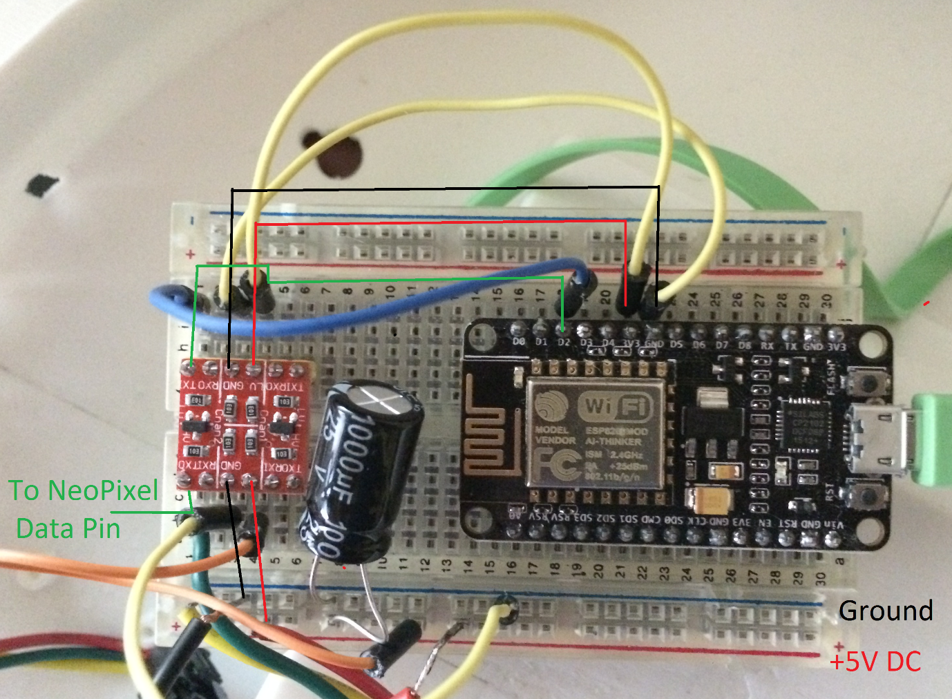
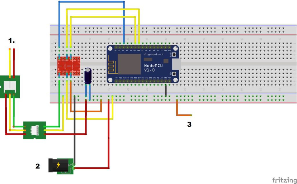
To get started we will build the board. We need to link the
NodeMCU12E to the NeoPixels, but because the pixels are 5V and the NodeMCU12E is 3.3v output on its pins, we will require a logic level converter. We need to connect 3.3v and GND to the logic level converter on one side, and 5V and GND to the logic level converter on the other side. Afterwards we can take an output from pin D2, put it on an input to the logic level converter and to the Neopixel input line.
We need to add a 1000uF 6.3V+ capacitor to the 5V power so that the inrush current won’t damage the NeoPixels. This isn’t crucial, but don’t come crying to me if you blow up your pixel strip if you didn’t have them :P
Wire 3 should be unplugged for now. We will plug it in later when we want to power the board off our DC jack instead of USB.
Installing the Board to Arduino IDE
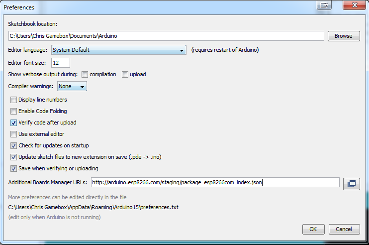
For this part you’ll need the Arduino 1.6.5 IDE (or higher).
The IDE for the ESP8266 is pretty new, so you’ll probably
need to install it. Open up File->Preferences and, under “additional boards manager”, simply add http://arduino.esp8266.com/staging/package_esp826...
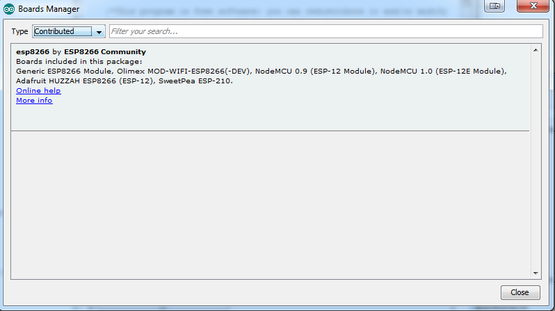
Now hit OK and go to “Tools->Board->Board Manager” and
select “type: contributed”, after which the ESP8266 board should show up.
Hit “Install” and go make a cup of coffee, this can take quite
some time. :)
Uploading the Code
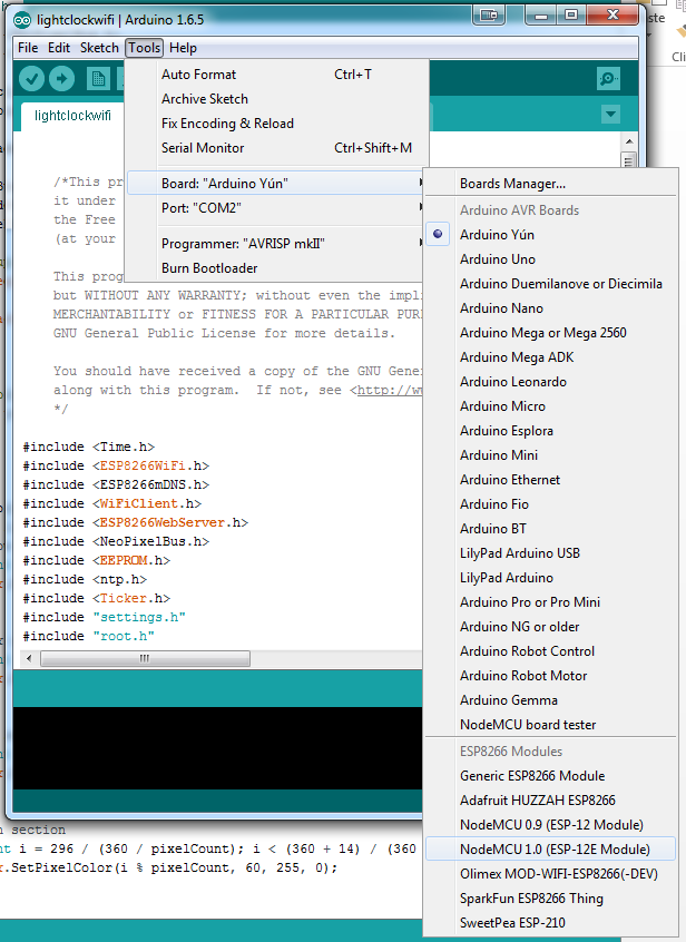
Once the board is installed you should be able to select the
correct board under Tools-> Board: NodeMCU 1.0 (ESP-12E Module). Of course, if you’ve bought a different version of the board, then select that particular one from the list.
You don’t program the ESP8266 like a normal Arduino chip. You’re actually over-writing the entire firmware on the chip. To do this you have to put it into boot loader mode.
Plug the board in, so that you should see the little blue LED light up. Then, hold down the “flash button” and briefly press the “Reset” button while still holding flash. This will put the unit in bootloader mode so you can then upload your code to it, which you can find on GitHub.
I have made a couple of modifications to some of the libraries which you can find here and here
Disclaimer: due to the fact that I’m am engineer in my everyday job, not a programmer, the code might miss a thing or two. If you notice anything which can be improved, please link back to me and let me know. :)
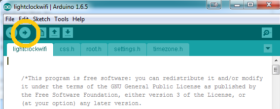
So, in order to upload it, unzip the file and open it in Arduino. Note: make sure you hit the right arrow, as the screenshot shows:
If the code doesn’t upload properly, go ahead and check whether all the required libraries are installed. There are quite a few of them! If you need help installing them, you can find it here.
Give It a Shape
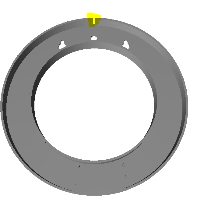
OK, so you have a long strand of LEDS connected to a
micro-processor. It might be pretty, but it sure isn’t a clock yet! For that you’ll have to build a body.
I’ve uploaded a 3D print to thingiverse which you can download. You may have to cut it into several sections in order to print, in case you’re using a smaller 3D printer.
Print this off. You have a little notch for the LEDs to poke through - put the wires here and make sure that you wind the LEDs around the clock CLOCKWISE, otherwise you’ll have to learn how to tell time backwards! :P
NeoPixels should come with backing tape, but if not, a bit of hot glue or bluetac can be used to keep them in place.
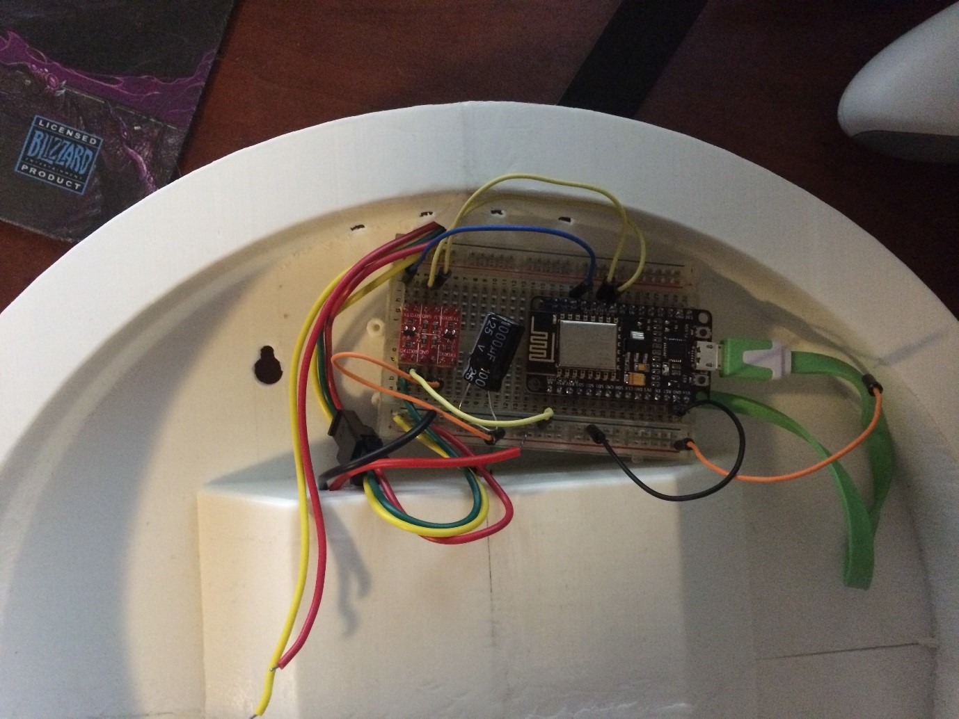
Mount our breadboard on the top of the donut like in the photo (which is from a different prototype, but it should do).
Add the Face
.JPG)
.JPG)
.JPG)
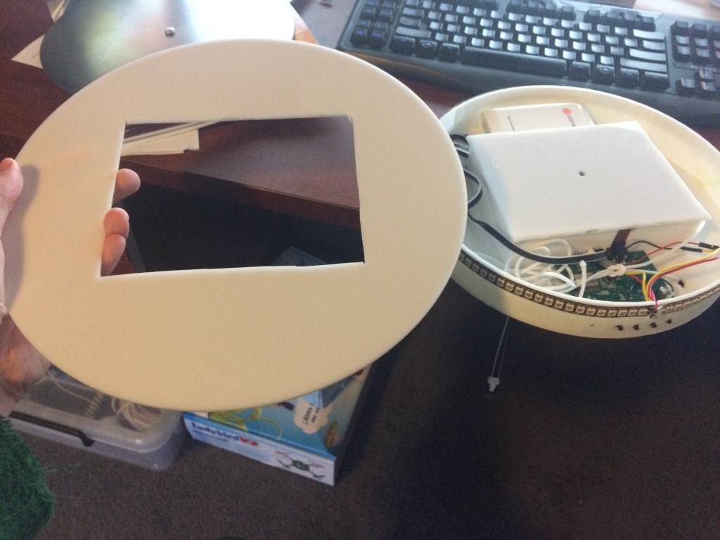
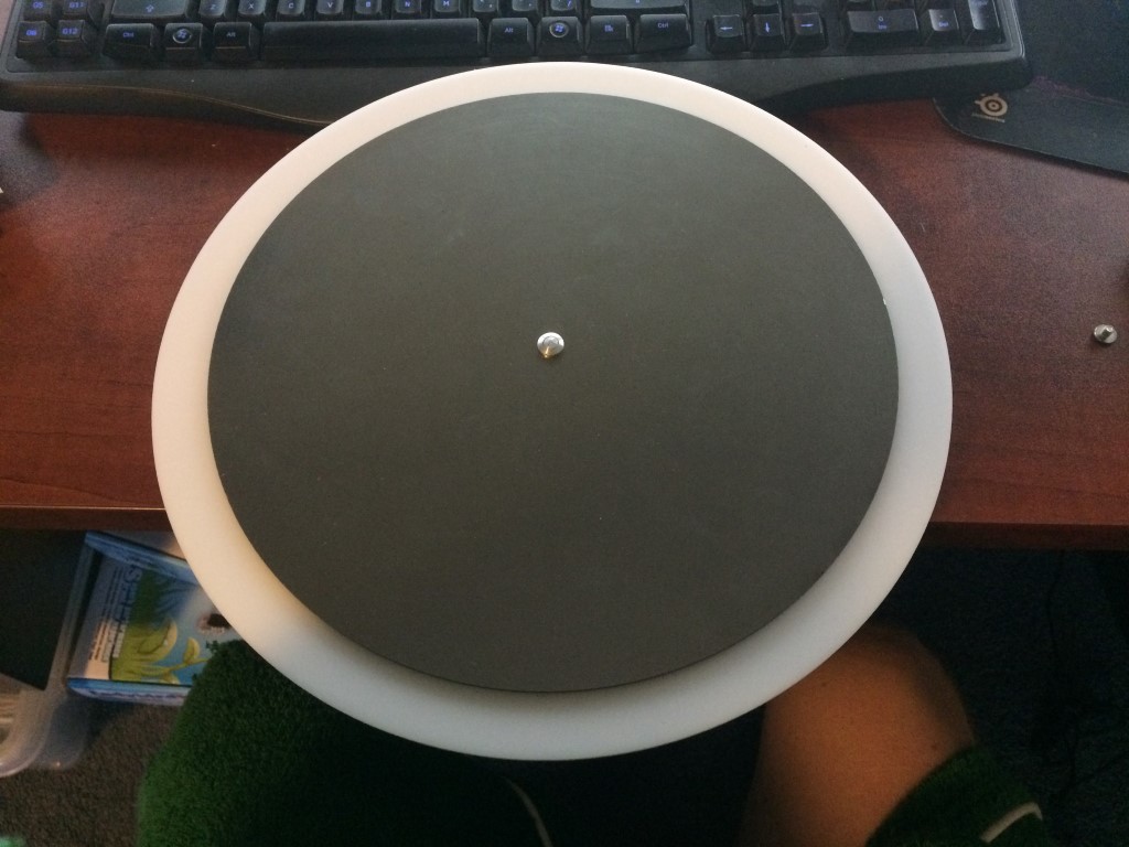
To add the face to the clock you will need a laser cut acrylic sheet and an "attractive" face. I use anodized metal, but you could use more acrylic, cardboard, canvas, wood. Whatever you like :)
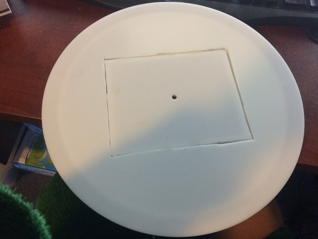
Cut a 300mm disc of acrylic, cut a 182mm circle out of the center, then drill a 5mm hole out of the center of that.
Glue the 182mm circle to the 3d part we printed earlier (the design in the photos is a square, sorry I have a lot of different prototypes)
Place the 300mm disc around the cutout section.
Bolt the "attractive" face (should be 260mm with 5mm hole in it) to the part to hold the whole thing together. I use "Chicago Post Screws" you can find them on ebay.
Add Power
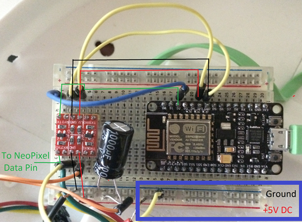
Screw in your DC jack into the hole in the centre and plug the wires into the breadboard on the 5V side:
Testing, Testing!
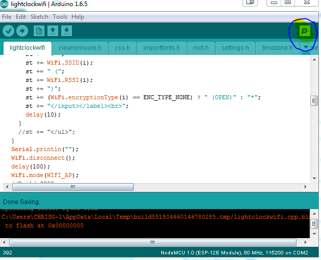
All you have to do now is to boot up the unit and test it. Make sure it’s plugged into the computer to the 5V power. Open up Arduino and click on the COM Port (highlighted yellow in the first image).
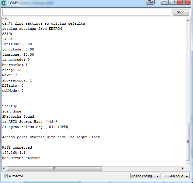
You should get a stream of data as the clock boots up with the default settings (second image).
The settings assume that you are in Australia, but don’t worry we can
change that.
Connecting to Your WiFi
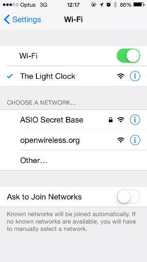
Now we have to set up the clock to be able to connect to your wifi network. You’ll need your phone for this.
First connect to “The Light Clock” wifi network. Because this network isn’t connected to the internet phones can sometimes take a little bit to do this. Just stick with it, you’ll get connected.
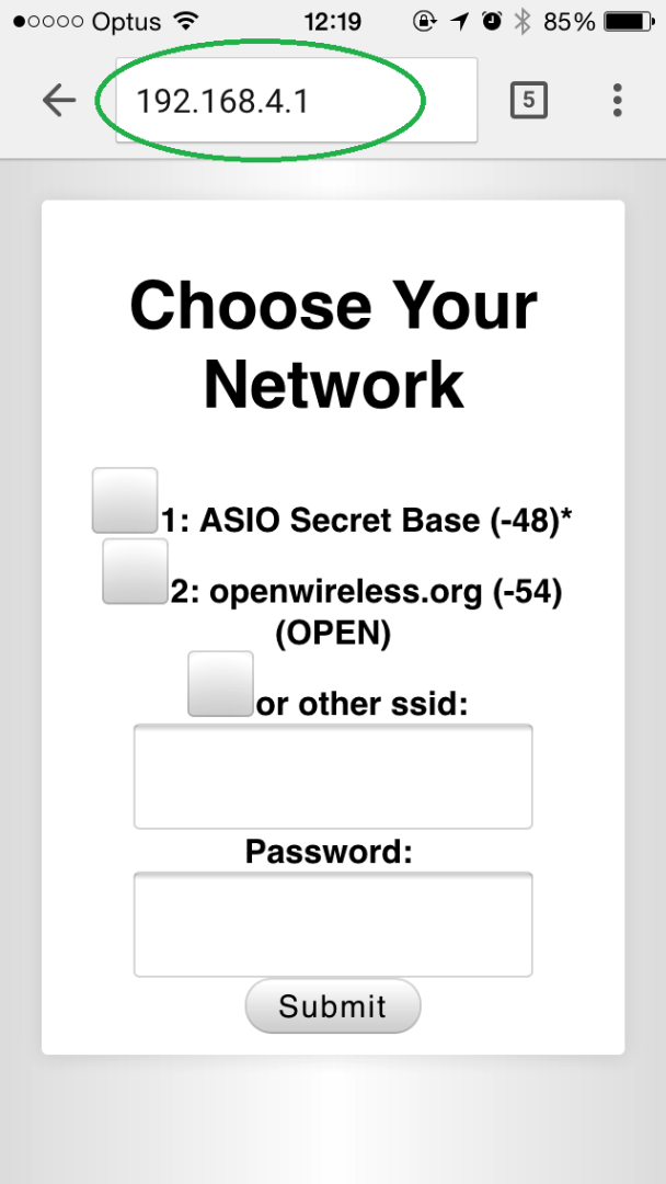
Then open your internet browser (Safari, Chrome, Firefox) and type “192.168.4.1” into the address bar (where you’d normally type www.instructables.com).
Select the wifi network you want your clock to connect to, type the password associated and hit “Submit”. Don’t get scared if the screen displayed is not exactly the same as the one shown in the picture above, functionalities are still the same.
Next, you’ll be taken to the time-zone menu, similar to the screenshot below. You can set your time-zone for anywhere in the world and the clock will keep perfect network time.
Whoo-hoo! High-five for a fully functional light clock built by yourself! Now just bear with me for a little longer, this is where we get to the fun part!
Customising the Colours

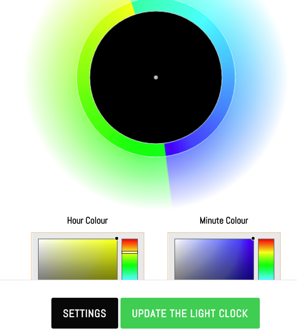
The whole colour spectrum is at your disposal, you just have
to make your pic! The light clock can display millions of colours, so you can customize it to fit any décor. Here’s how.
Special step for PC: To find the clock on your network, we use a service called mDNS. This works natively on all Apple products (Macs, iPhones, iPads), but you need to install a little helper if you use a PC. Once this is installed you can move to the next step: finding your light clock.
Open your browser and type in thelightclock.local/ (make sure you DON’T type www first and make sure you DO type the “/” at the end).
You will now end up in the main menu, where you can change
the colours by clicking on the hour or minute colour. Hitting the “Update the light clock” button will make your clock on the wall apply the new colour scheme you just chose.
Other Settings

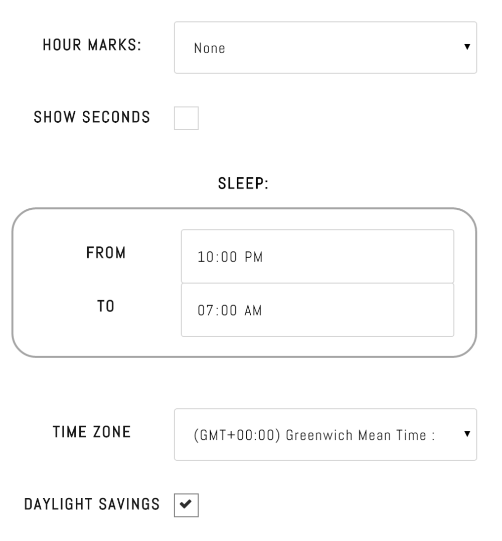
If you hit the "Settings" button down the bottom you'll find a host of other things you can play with. Would you like a seconds hand? Should the clock dim itself at night? Would you like little markings to help you tell where there hours are? All of this and more are customisable in the settings menu
You're Done!
Thanks for reading and watching :) If you like this clock and want to support us on Kickstarter that would be awesome. If you built your own and want to let me know how it went that would be awesome too!