The Land Fill Bot
![GridArt_20231026_151520077[1].jpg](/proxy/?url=https://content.instructables.com/F2N/ERBB/LO7730BM/F2NERBBLO7730BM.jpg&filename=GridArt_20231026_151520077[1].jpg)
![IMG_20231025_154736_290~2[1].jpg](/proxy/?url=https://content.instructables.com/FAU/1ZTN/LO62P1V9/FAU1ZTNLO62P1V9.jpg&filename=IMG_20231025_154736_290~2[1].jpg)


Welcome inventors
I will show you how to make a simple user-friendly remote-controlled landfill robot—equipped with LED status indicators, a photoresistor (to turn on the night light), buzzers, and even a gesturing hand to welcome every visitor who wishes to dump their trash conveniently. This will make as a fun Arduino project!
There's a saying that goes: 'Another man's trash is another man's treasure'. So who knows what useful things we may find today?
Supplies


Tools & Materials
- Cardboard box (13 × 8 × 9 in)
- 2 x Bottle caps (Diameter: 4cm)
- 1 x Bottle cap (Diameter: 3.5cm)
- Metal Rod (Length: 8cm)
- Hole puncher
- Box cutter
- Scissors
- Glue gun
- Soldering iron (optional)
- Maths set (Pencil, Eraser and Ruler)
Electronics
Almost all the electrical components in this build can be found in the Arduino Starter kit. The electronics used are as follows:
- Arduino UNO R3
- Stepper motor and driver
- Servo
- An active buzzer
- RGB Led
- 3 x 220-ohm current-limiting resistors
- 9-volt blue LED (or you may use a blue LED in the kit with another 220 ohm resistor)
- Photoresistor
- 10k ohm resistor
- Arduino Infrared Remote
- IR receiver
- Large breadboard
- Programming USB cable
- 5 wires (10cm each, preferably different colors)
- A dozen Male to Male Jumper cables
- A dozen Male to Female Jumper cables
Making the Arm


This arm will later be attached to the bin which dumps its contents into the landfill.
- Get the 4cm diameter caps and use the box cutter to cut a small square on its circumference, we will now use the hole puncher to make a hole in the centre of the second cap.
- Partially insert the metal rod inside the bottle caps square cut then glue the other cap directly on it, thus making the rod secure.
- Get the 3.5cm cap and similarly use the hole puncher to make a hole at the centre. Now we will partially insert the rod inside the cap and glue them together.
- Be sure to keep the Stepper motor nearby. Pour glue inside the hole of the 4cm cap then insert the shaft of the Stepper motor cautiously inside the hole so as not to glue the motor itself to the cap.
Creating the Body Part 1


We will now get the dimensions and cut out all parts for the body, except for the bottom section (not needed).
Dimensions:
Top/Sides: 8cm wide and 10cm long
Front/Back: 8cm wide and 10cm long
All measurements are shown in the pictures above
- On the left side, we will use a box cutter to cut out a rectangle the size of the servo, and then on the right we will cut a rectangular piece for the wires that would later leave the robot's body for our breadboard and Arduino UNO.
- We will now use glue to attach the servo in place. In continuation, we will glue our arm in such a way that when we rotate the arm its front cap always appears to be ahead of the body, thus preventing any positional errors.
Creating the Body Part 2


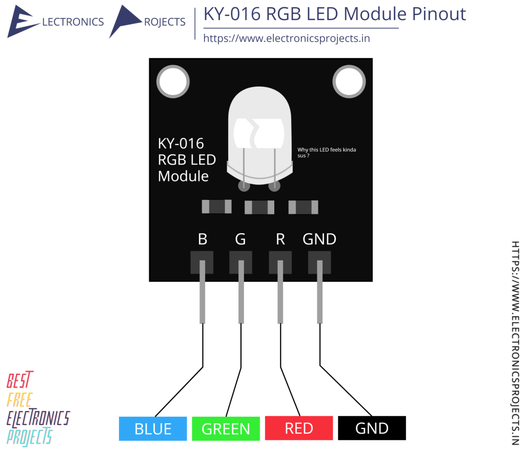
- We will get our top body section and from 3cm we will mark out the lengths for the IR receiver, RGB LED, and the photoresistor as seen in the pictures. After cutting appropriate rectangles using the box cutter we insert their pins inside each one respectively and glue them in place.
- Now we are going to connect wires to our components, you can differentiate each pin using different colored cables for the grounds, voltage supply, and signal pin (Please note that photoresistors do not have a polarity, their pins are symmetrical).
The links for the pinouts of the IR Receiver and the RGB LED are highlighted.
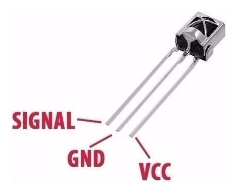
- Firstly, we will insert male-to-female cables into our RGB LED. For the other components to get a secure connection, we will use hot glue or solder to wire the other components with the 10cm long wires and extend them by connecting a cable (male-to-male) as I've shown in the pictures above.
- Now to complete the body we will bring the wires out through the right side cut out and glue all our sides together, and then we will glue the back part of the body. We will not glue the front piece of our robot yet in case we have any connection issues inside, thus making it easy to correct during our build.
Platform & Attaching the Bin


- Utilizing the cardboard box, cut out the platform for the robot which can include flaps as seen in the pictures.
- Glue the robot to the top right corner, leaving a 10cm gap.
- Now we will connect male to female jumper cables to the stepper motors driver inputs 1,2,3 and 4. Also, we would connect cables to the voltage and ground pins.
- Furthermore, we will now plug our Stepper motor into the driver.
- The next step is to make dimensions for our bin.
Bin Dimensions:
Sides: 4cm wide, 6cm long
Top/Bottom: 4cm wide, 8cm long
Front/Back: 8cm wide, 6cm long
Hinges: 1cm wide, 4cm long
- After marking out the dimensions we will use scissors to cut the pieces and glue them together except from the top and the hinges.
- Now, we will glue a part of the hinges to the top of the bin and the other part to the back of the bin.
- The bin is now complete! All we now do is place the bin in front of the arm and mark where the bin and the arm are in their standby position by using a pencil against the 3.5cm cap and the back of the bin.
- We will now use sufficient glue to attach the arm to the bin.
Making the Hand


Measure the width of the hand which is 2cm, and also measure and cut out a rectangular piece for the torq servo arm of the servo (1.7x0.3cm) which we will be using to control the hand. Then we will glue the hand to the servo arm.
This hand is used to indicate the availability of the machine, in the program the hand will rotate backwards to a180-degree angle, allowing the bin to operate and dispose of its contents.
Connecting the Breadboard & Arduino


Power Supply
1. Connect the stepper motor driver's VCC or positive pin to a separate power source (directly to the Arduino).
2. Connect the stepper motor driver's GND or negative pin to the ground of the same power source.
3. Connect another 5V power source and ground to the breadboard for the common 5V supply shared among the servo, IR receiver, photoresistor, RGB LED, buzzer, and LED.
NOTE: Ensure that all components sharing the common ground are connected to the same ground terminal.
Stepper Motor and Driver
5. Wire the stepper motor driver's input pins: 8,9,10 and 11 as seen in the pictures above.
Servo Motor
6. Link the servo motor's signal wire to an Arduino to pin 7.
7. Power the servo motor's red wire from the common 5V source.
8. Connect the servo motor's ground (usually brown) wire to the common ground shared with other components.
IR Receiver
9. Supply the IR receiver module's VCC or power pin from the common 5V source.
10. Connect the IR receiver module's GND or ground pin to the common ground.
11. Route the IR receiver module's SIGNAL pin to an Arduino input pin 2.
Light Sensor (Photoresistor- turns on the LED in dark areas)
12. Connect one leg of the photoresistor to the ground.
13. Connect the other leg of the photoresistor to a 10k-ohm resistor.
14. At the junction between the photoresistor and the resistor, connect it to analog pin A0 on the Arduino.
15. This configuration allows you to measure the light level using the photoresistor, with the analog value read from pin A0.
RGB LED
16. The RGB LED consists of three separate LED pins - Red, Green, and Blue, connect them each to a 220-ohm resistor.
17. Connect the other end of each 220-ohm resistor to one of the digital output pins:
- Red LED: Connect to pin 4.
- Green LED: Connect to pin 5.
- Blue LED: Connect to pin 6.
18. Connect the GND pin of the RGB LED to the common ground.
Buzzer
19. Connect the positive lead of the buzzer to an Arduino digital pin12.
20. Connect the negative lead of the buzzer to the common ground.
LED (9V)
21. Connect the positive lead of the 9V LED to an Arduino digital pin 13.
22. Connect the negative lead of the 9V LED to the common ground.
Everything should now be connected and ready to program!
The Programming Part

.png)
.png)
.png)
.png)


1. Start by obtaining the Arduino IDE:
- Download it from the official Arduino website.
- Follow the installation instructions for your specific operating system (Windows, macOS, or Linux).
2. After installation:
- Launch the Arduino IDE.
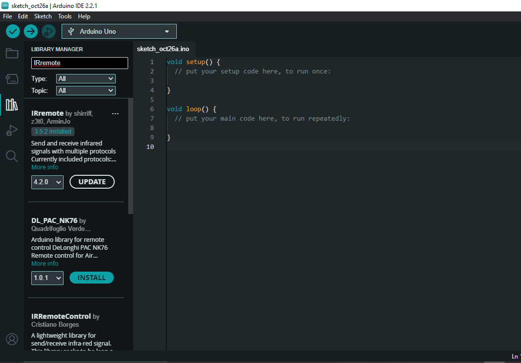
3. Install the "IRremote" library:
- Access the Library Manager by going to "Tools" in the menu.
- Choose "Manage Libraries."
- In the Library Manager, search for "IRremote."
- Look for "IRremote by shirriff" (I used version 3.5.2) and click the "Install" button.
- Wait for the installation process to complete, and you'll see a confirmation message.
4. Open a new sketch:
- Click on "File" within the Arduino IDE.
- Select "New" to create a fresh sketch.
5. Copy the provided code:
- Highlight and copy the code you have.
- Paste the code into the new Arduino sketch.
6. Save the sketch:
- Save your new sketch by going to "File."
- Select "Save As."
- Provide a name for your sketch and choose a location to save it.
7. Connect your Arduino board to your computer:
- Use the USB programming cable to establish the connection between your Arduino board and your computer.
8. Configure the IDE for your specific board:
- In the Arduino IDE, navigate to the "Tools" menu.
- Select the appropriate board from the "Board" menu, e.g., Arduino Uno.
- Choose the correct port corresponding to your connected Arduino board from the "Port" menu.
9. Upload the code to your Arduino:
- Click on the "Upload" button, usually represented by a right-pointing arrow icon, within the Arduino IDE.
- Wait for the code to compile and upload to your Arduino board.
10. Test your remote by monitoring the Serial Output:
- If you want to view the output from your Arduino, you can open the Serial Monitor.
- We will access the Serial Monitor either by clicking on the magnifying glass icon or by going to "Tools" and selecting "Serial Monitor."
Button functions
The Serial Monitor, provides the buttons pressed, as seen in a picture some hexadecimal numbers are displayed representing that the 1, 2 and 3 buttons have been pressed earlier.
- Button 1: The robot buzzes then the hand (servo motor) moves to a 180-degree position, indicating the initiation of the waste disposal process. The bin (stepper motor) moves forward, disposing of waste. After a set period (2 seconds), the bin is moved back to its initial position. The RGB LED changes to green, signaling the successful completion of the waste disposal. The buzzer briefly sounds again, indicating the end of the process. The hand (servo motor) returns to its initial position (90 degrees), marking the completion of the function.
- Button 2: initiates a greeting, so visitors and passers-by can observe the light show with color changes and a wave action from the hand.
- Pressing Button 3 activates the alarm feature. The RGB LED will turn red, and the buzzer will produce an alarm sound to get your attention.
NOTE: You may need to change the outcomes in the code for the buttons used in your remote e.g.1, 2 and 3 in case you have a different specification.
The robot should now be operating as expected, hold on, almost finished now!
Now, we have successfully set up the Arduino IDE, installed the necessary library, uploaded the code, and we're now ready to interact with the circuit as described in the code.
Downloads
A Few Touches


Bring out the front piece of your robot. Now that we've established everything is working we will give our robot a name!
Glue the front piece to the robot then we may glue the 4 corners of the Stepper motor drive to our platform to keep the electronics tidy and in place.
Building the Barriers for Our System


We will make the barriers on the left side of the compound 10cm high and on the right side 6cm high adding a little barrier (2cm high) behind our bin; make sure to cut out a square at the corner of our build to allow our robot to receive power outside the vicinity via the USB from a power bank, charger head or laptop,
Depending on the size of your premises the lengths of the walls will differ. I've mentioned the lengths of the one used here in a previous image (step 4). The first picture seen above is a folding cut-out for our electronics compartment which will contain the Arduino, driver, and breadboard, which includes holes for the Stepper motor wires and the programming cable.
Now that we've glued all the divisions in place we can officially put this robot into action!
All Done!


Take your robot to the real world and explore its limits! Which I found to be 2-3kg worth of trash : )
Hope you enjoyed this build and thank you for following till the end.