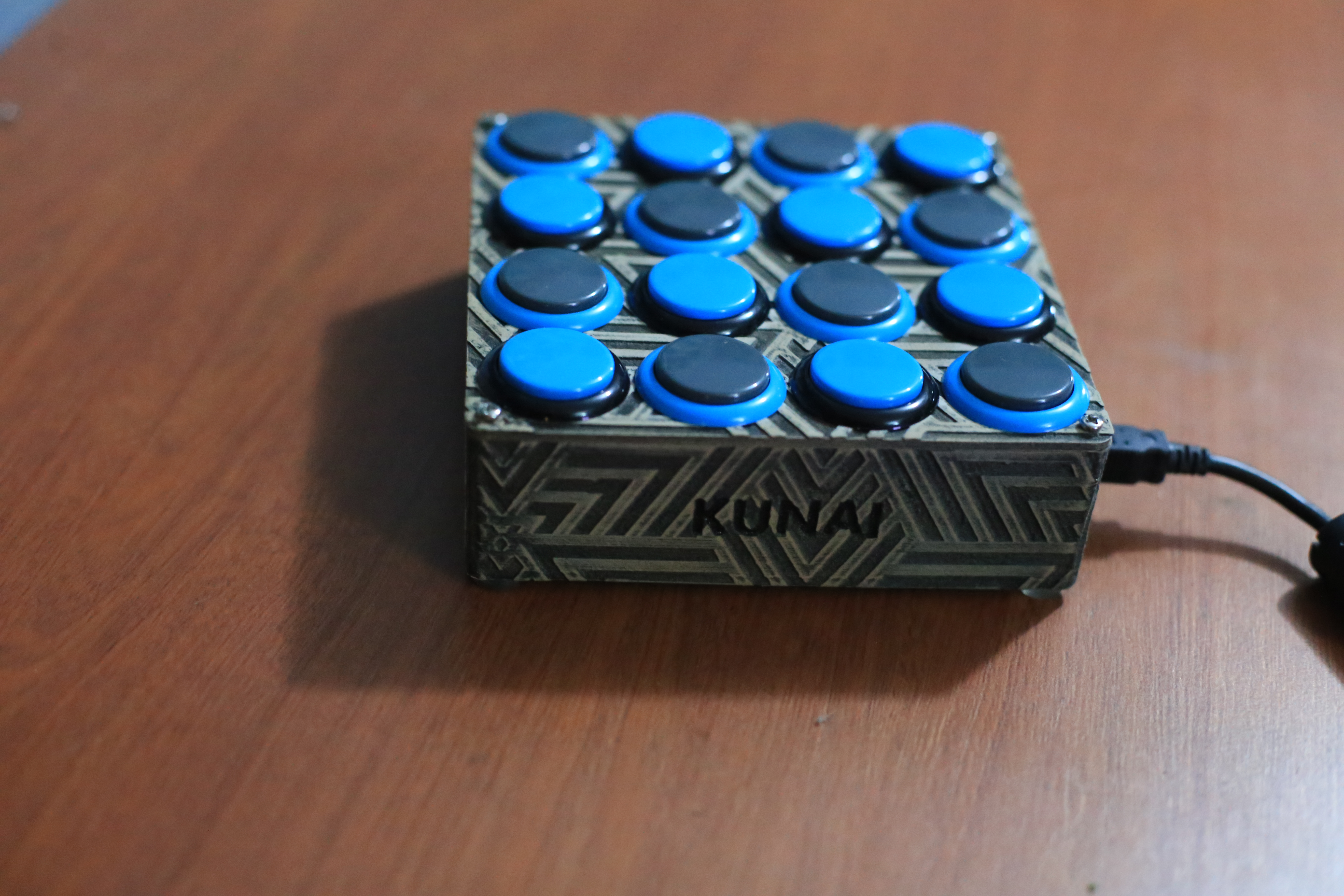
The KUNAI MIDI CONTROLLER
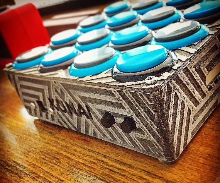
The KUNAI is a 4 x 4 MIDI controller that uses the highest quality; Japanese SANWA buttons , has as many banks as your DAW can handle, a touch filter , and completely customizable and modular!
This is a project I have finally started to perfect after starting to work on a remix of this midi controller posted on DJTT by Kyle Mohr! https://djtechtools.com/2015/08/25/how-to-make-yo... I have since then moved from wires to a custom made circuit board to clean things up , cleaned up the code, and added a few features! :D
Required Materials
You will need:
-TEENSY LC Micro Controller]
-At least 120x120mm Single Layer Copper Board (I purchase a 300x300 sheet on amazon for $20 that makes 4)
-Male Micro-B to Female-B panel mount
-Spectra Symbol Soft Potentiometer
-10k Resistor
-x16 SANWA arcade push buttons
-x4 3mm LEDs
-x2 12mm Tactile Push Buttons
-x32 3577 fuse clips ( if you want the buttons to be removable from the PCB [HIGHLY recommended]
x4 30mmx2.5mm (M3) screws
-Ferric Chloride
-Elmers Glue Stick
-Soldering Iron & Solder
-1mm drill bit
-3D printer
-3D printer filament in desired color
-2mm single layer copper board
-Glass or Plastic container
-Hot Glue
-Small gauge wire
3D Modeling the KUNAI
The best part of The KUNAI is that the enclosure is fully 3D printed, allowing it to be VERY easily customized with minimal effort.
I have included the base files for The KUNAI which have no embossment patterns on it so you can simply drag and drop a pattern into your 3D modeling program, get a 3D stencil from that, and then subtract it from the walls of The KUNAI , causing that pattern to be engraved onto The KUNAI walls.
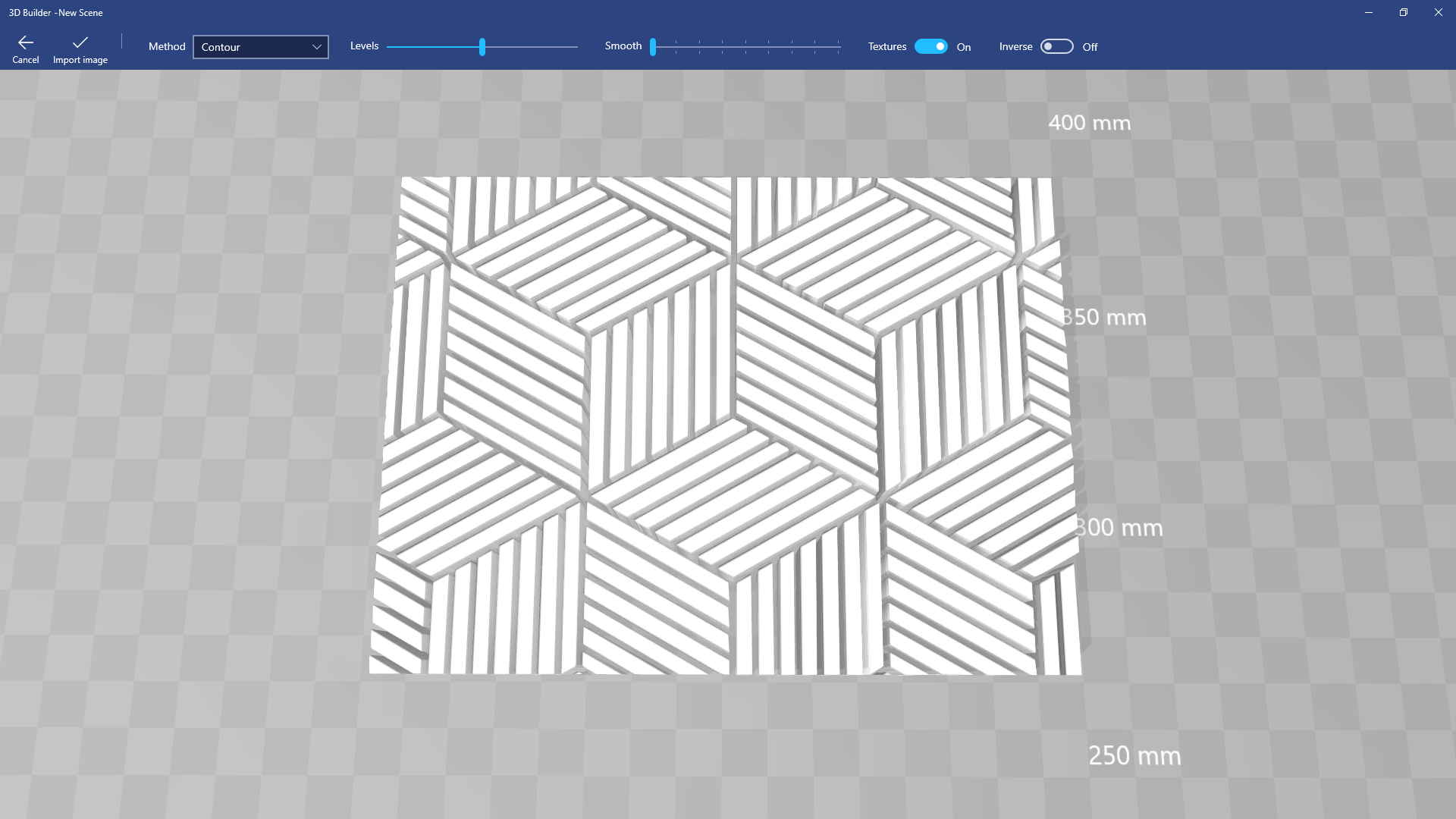
To do this simply follow these steps: -Download & install "3D Builder" from The Microsoft store
-Find an image you would like to use as the pattern on The KUNAI and drag and drop it into 3D Builder
-You will be given options at the top... Disable Textures, change the levels & smoothness until you achieve a desirable result. You can also use the "Inverse" option to reverse the embossment which will reverse which edges are sunk into the walls and which remain at the same level. After you are done with these options, click on "Import Image" at the top left, and you will be given a 3D model made from a photo.
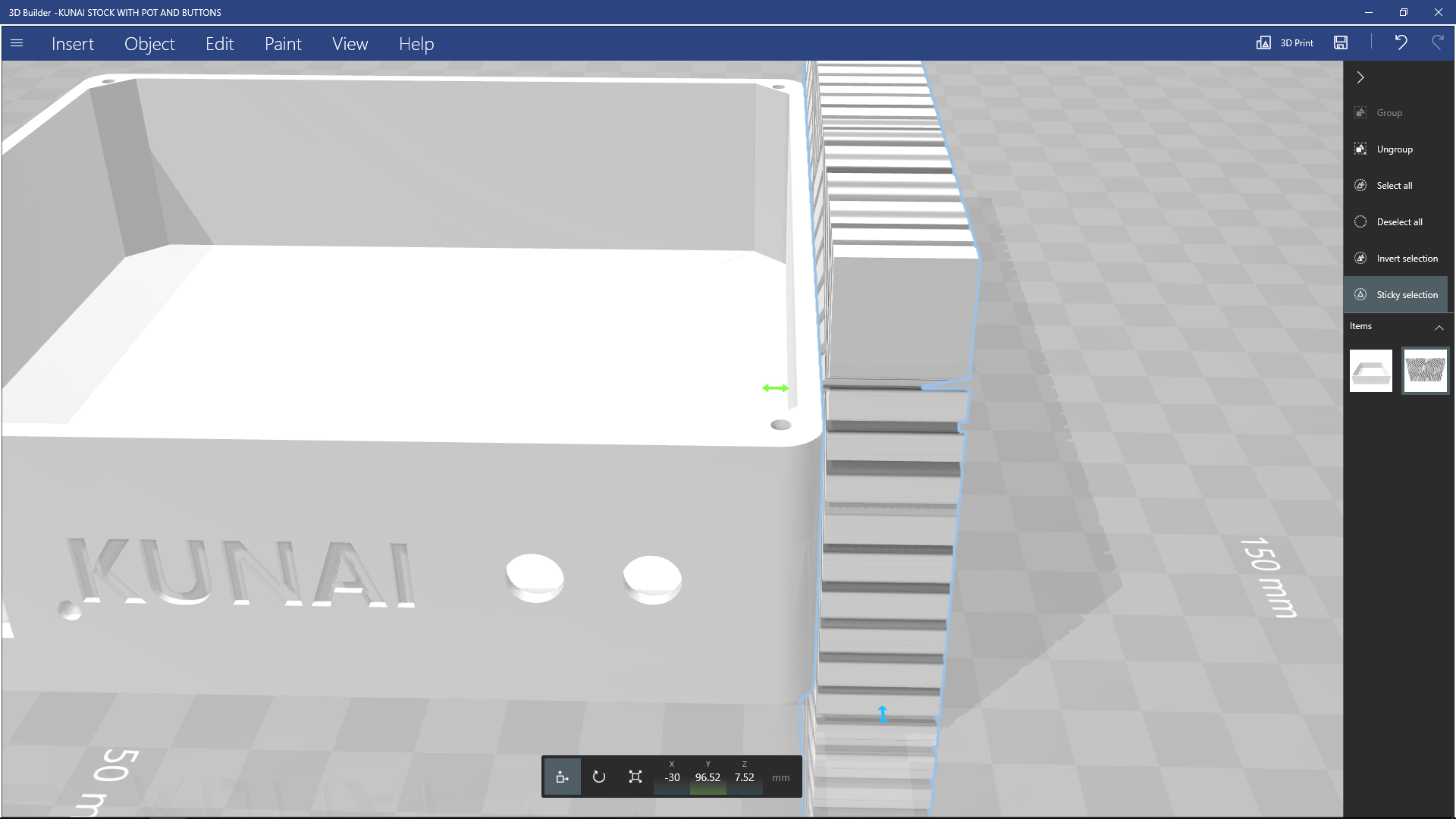
- Next step is to open a SECOND instance of 3D builder , and open The KUNAI base files
-Go back to your pattern once The KUNAI base has been opened, and ctrl + A to select all, and ctrl + c to copy the model
-Now go back to The KUNAI base model , and ctrl + v to paste the model
-With your model now posted beside The KUNAI , select the rotate tool from the bottom that's shaped like a rotating arrow(or "E" if you're having trouble finding it), you will then adjust the Rolll, Pitch & Yaw of your pattern to align it with the walls of The KUNAI
-Once you're happy with the orientation of your pattern, select the move ( or "R" if you're having trouble finding it)
and move the pattern flush with the wall of The KUNAI; it should "SNAP" into place once it's flush.
-Now with only the pattern selected, ctrl + c to copy it in its new position ( this will save time for each wall )
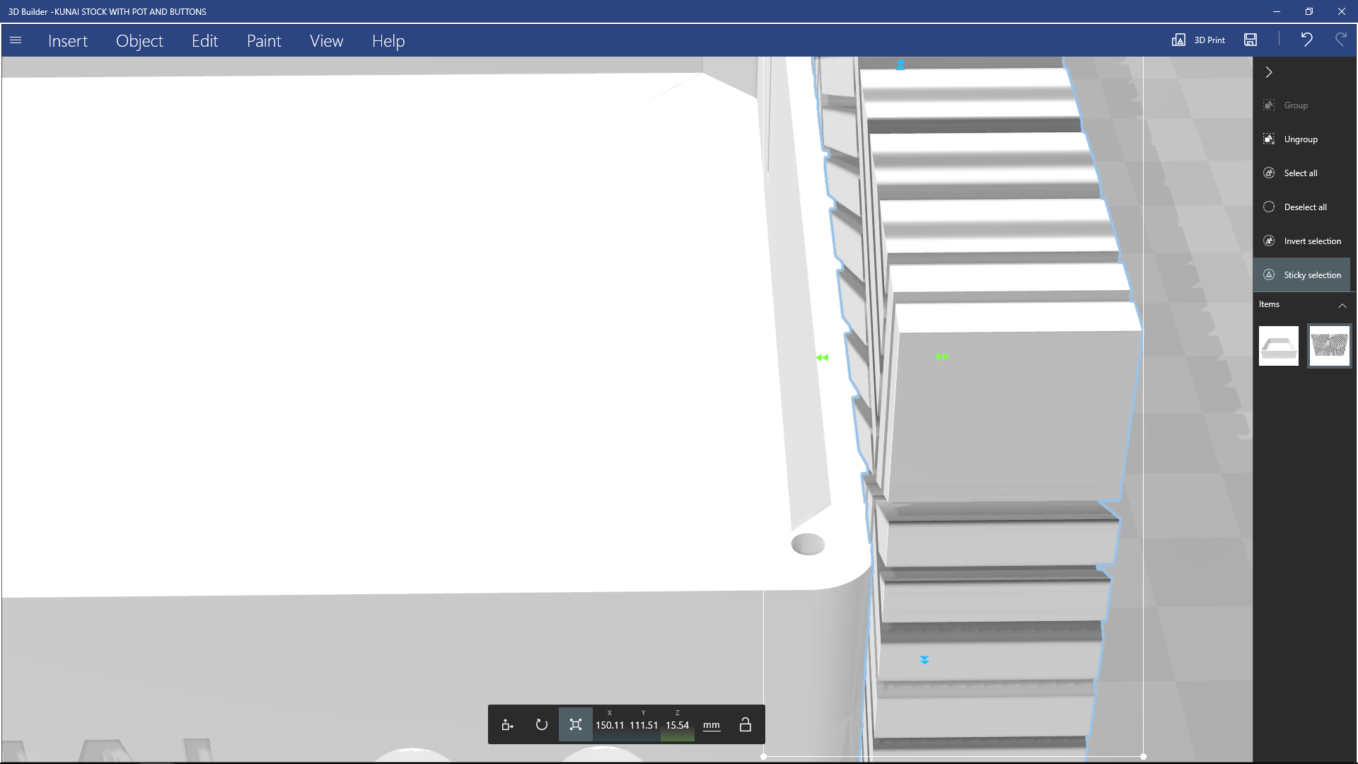
-With only the pattern selected, we want to chose the "SCALE" tool ( Q if you're having trouble finding it ),
pay attention to the number under "Z" , as this is your patterns base thickness, and now drag the arrow facing the center of The KUNAI towards the center of The KUNAI , until the Z value is 0.5mm greater than it was originally ( this will be an embossment with a 0.5mm depth )
-Now click on "Edit" at the top, and select "Subtract" from its secondary bar to create the embossment!
-You will notice The KUNAI now has a pattern on ONE of the walls, but we still need the other 3! This is why we copied the pattern before editing it any further! Simply ctrl + v to paste the pattern back in the exact same spot it was in before you pulled it into the walls for embossment
-Simply select the pattern that you just pasted ( ENSURING ONLY THE PATTERN IS SELECTED ) , and use the MOVE TOOL "R" , to move it to the opposite wall and repeat the process
-For the last 2 walls ( that are facing 90 with the initial wall ) , after you do the second subtraction and paste the pattern for a third time, select the rotate tool (E) , and rotate it 90 degrees and then follow the same steps again!
Once you're happy with the Pattern on The KUNAI walls. Save the file as a .STL , .OBJ , or .3MF.
-Now do all that again for the top cover >:} ( just simply put your pattern ON TOP of the cover and subtract from that )
TADAA!!!! 3D modesl done... Now 3D print them! ( I recommend printing it with PLA @ 20% infill , 2 walls, 0.3mm layers )
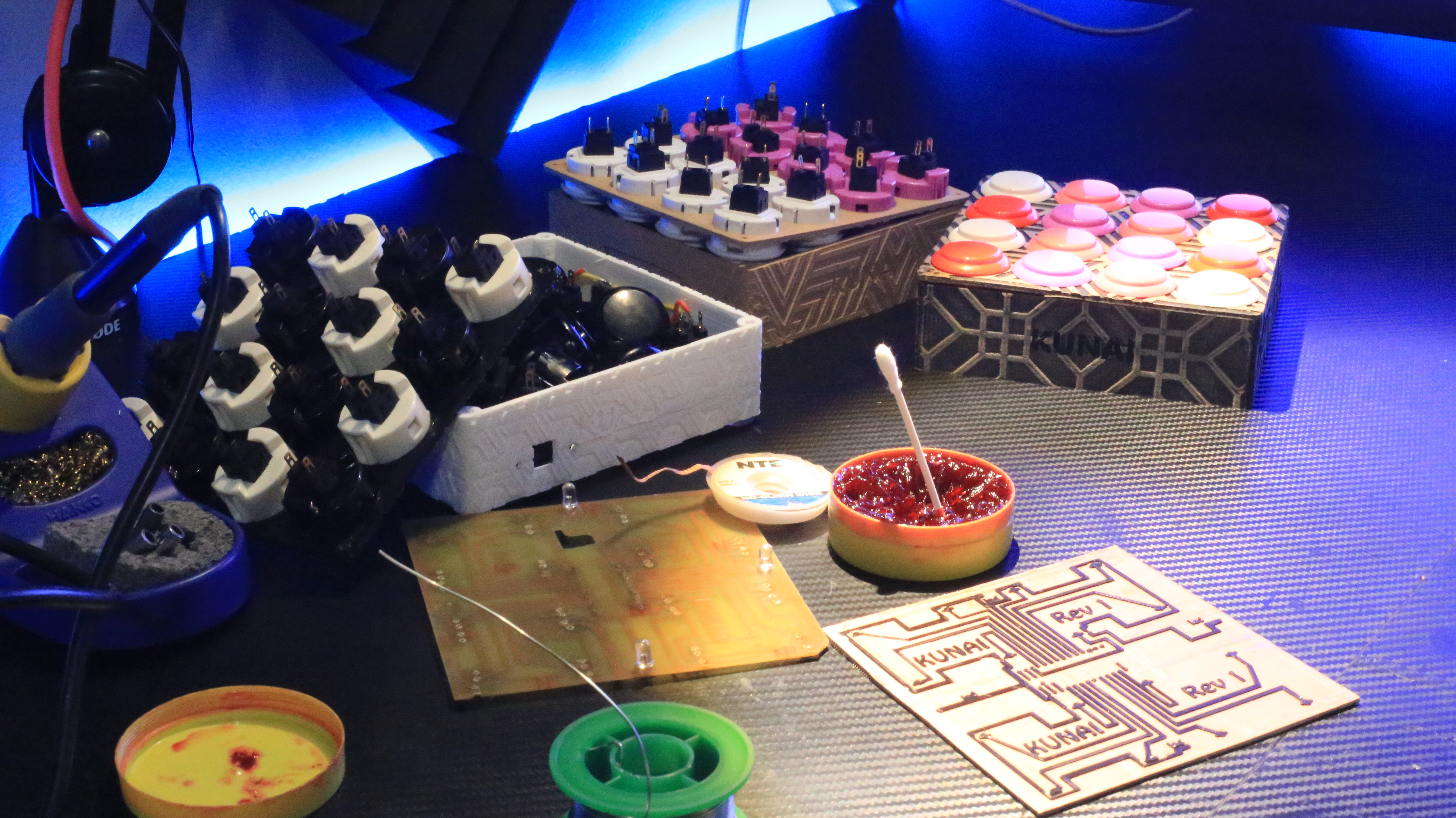
The PCB ( Printed Circuit Board) Step 1/3
So... This is where things get a little weird, especially since there's multiple ways to do this.
If you're lucky enough to own a 3D printer, I have already done all the brain work to turn your 3D printer into a circuit board creator extraordinaire WITHOUT having to do ANY kind of modifications!!!
To prepare your 3D printer for making circuit boards, simply drop the bed at least 2mm from level, and literally that's it! ( for the printer )
Now securing your Copper Board to the printer is the little more complicated part , and where your double sided tape comes in.
-Simply take your double sided tape, and tape the back of your Copper Board; ENSURING that the corners and the middle at least have tape on them ( the tape I use is about the thickness of duct tape, and using 3 strips only leaves a very small gap that's not covered )
-Now remove the protective back from the tape, and drop the Copper Board onto your 3D printers bed as square as possible ( I use a 150mm sheet of copper to make a 120mm board to leave room for error due to it not being perfectly square... and because I buy my sheets in 300x300 packs :3 )
-Now level your printer as you usually would, but instead of using the corners of the bed as reference points to flat, use the corners of the copper board ( if your using the on board level option on your 3d printer, level it to the middle, wait for it to get to the lowest point it gets, then turn your printer off , or send the "DISABLE MOTORS" command via your slicer, and manually move the print head and bet to get to the corners of the board)
-Once your board is leveled, take your Elmer's Glue and cover the copper with at least 3 layers ( IMPORTANT , TOO MUCH IS BETTER THAN TOO LITTLE ) , I usually do a vertical pass, horizontal pass, and then another vertical pass, or until the glue is visibly cloudy on the copper
-After all these steps are complete , simply load the included "traces" 3d model into your slicer , set your nozzle temp to the high end of the scale for your filament , set your bed to 60 degrees (Haven't tested with an unheated bed) set the walls to "4" , 100% infill , 0.3mm layers, solid diaphragm ever 1 layer ( if you have the option ) , and you may have to mess around with single extrusion settings to get a solid fill on the traces. I also recommend using 2/3 skirts 4-5mm away to prepare the nozzle, and also find out if your board is properly lined up on the bed.
-Once you have the model loaded up and the print settings set, print! -Pay close attention to the skirt when the print first starts, if it prints the whole skirt onto the board , and nothing is lifting / peeling off the board, the rest of the print SHOULD go through no problem!
Once your board is finished printing , it's onto step 2 of 3 of the PCB making process!
The PCB Step 2 / 3
Once your copper board is finished printing, it's time to get ready to etch it.
-Remove your RAW PCB from the printer bed and remove any tape still attached to it....prying with a 3D printing chisel with the bed a little warm helps!
-Now run your board under the tap set to hot at maximum pressure ( assuming your sink doesn't shoot lasers ) to melt any of the extra glue off! It doesn't hurt to use a paint brush to try and help get any left over glue out from in between traces that run close to each other ( like the center traces and the ones along the edges ), FAILURE TO REMOVE ANY GLUE WILL RESULT IN THE COPPER NOT BEING ETCHED, AND POSSIBLY SHORTING OUT YOUR BOARD IF NOT CAUGHT EARLY ENOUGH!!!!!
-Place your RAW PCB into a plastic container or pyrex / glass dish ( ANYTHING BUT METAL )
-Pour some Ferric Chloride onto the RAW PCB, until its fully submerged
-Now shake shake shake! Constantly agitate the Ferric Chloride by shaking your container, twisting it, rocking it back and forth , what ever, just keep it moving, and switching directions SEEMS to help.
-Your board is done etching once you see NO copper left anywhere on your board ( I wouldn't bother checking on it before 10 min or so )
-If you're unsure if it's done ( seems patchy ) , simply remove the board from the Ferric Chloride, run it under some cold water, and inspect it closely , if there's copper left, run that spot under hot water and give it a shake in the Ferric Chloride again for a few min! If that copper doesn't want to etch, it probably still has glue over it, so simply use your paint brush and warm water to remove the glue from there and either submerge it back into the Ferric Chloride , or you can dip your paint brush into the Ferric Chloride and repetitively paint of the spot that the remaining copper is to remove it without having to submerge the whole board again!
-Once you're convinced that all the copper in the negative space ( spots with no 3D printing on it ) has been etched, simply rip off the 3D printed layer using tweezers or a chisel!
-Now you should have a completely blank professional looking PCB you made at home for only a few dollars! (You're welcome) , now take that PCB and run it under water and rub off any glue left over on the traces.
-Now take some steel wool , and give the traces a nice clean & shine!
ONTO STEP 3/3 of the PCB process!
The PCB Step 3/3
Once you have your blank PCB rinsed and polished , it's time to simply cut it to size and drill the holes for all the components!
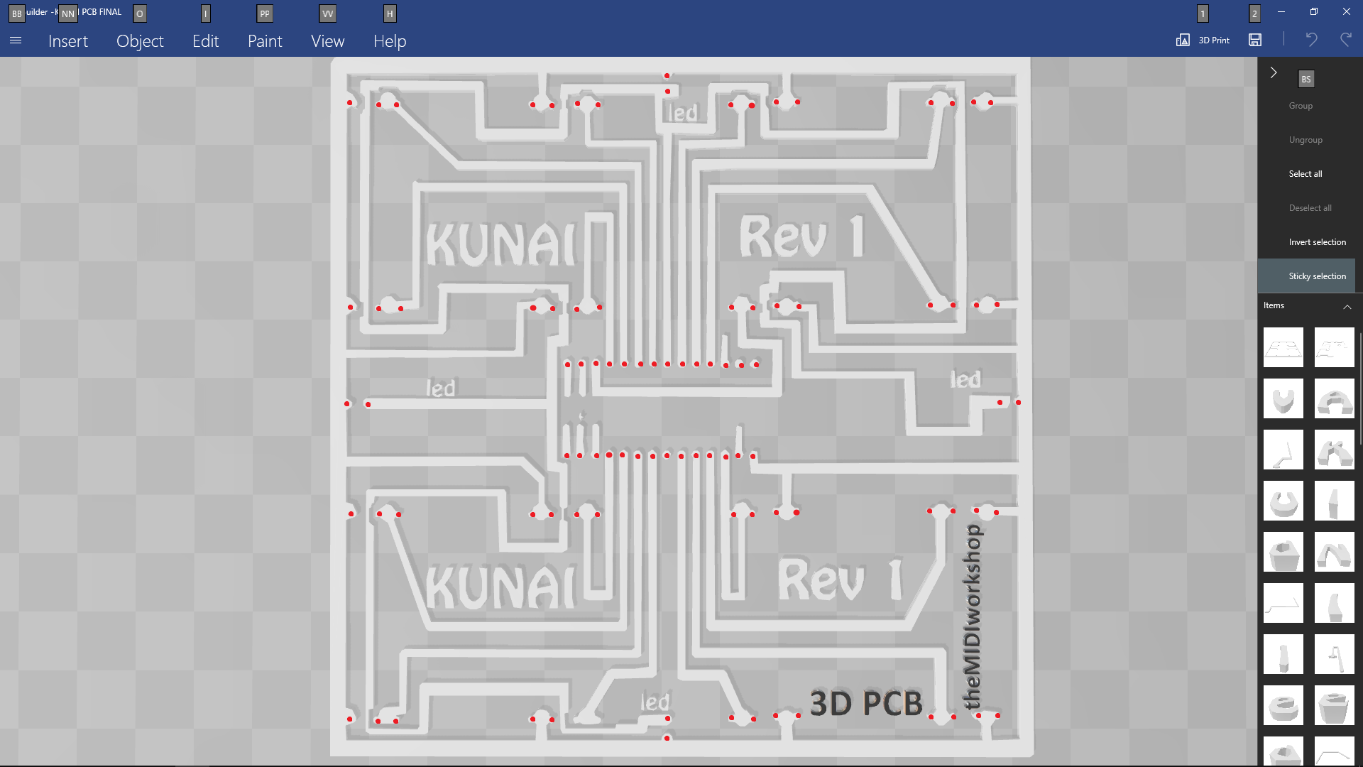
-Using a 1mm drill bit, prepare your eyes, hands and mind to drill 90 holes manually
-The drill holes are a little hard to identify at first, but long story short , it's anything that looks like a nipple or circle ( attached photo with circled drill points )
-Once you've drilled all 12982309182 holes, cut the board to size buy following the OUTSIDE edge of the big trace the runs along the edge of the board ( Ground Plane )
Now to fill them holes ;)
This part is simple enough! All components should be mounted on the OPPOSITE side of the traces so that the tail end of the component is only sticking through to the side where the traces are ( picture attached ).
The TEENSY should be mounted with the USB port facing the LEFT EDGE of the board if you're looking at it from the blank side while it's correctly oriented.
The Fuse Clips should be oriented with the slit facing the bottom edge of the board if you're looking at it from the blank side while it's correctly oriented
LED's should have the shorter end going through the trace at the edge ( GROUND ) , and the longer one onto the thinner trace the runs along the ground trace all the way around the board ( 5V )
now simply solder everything from the other side!
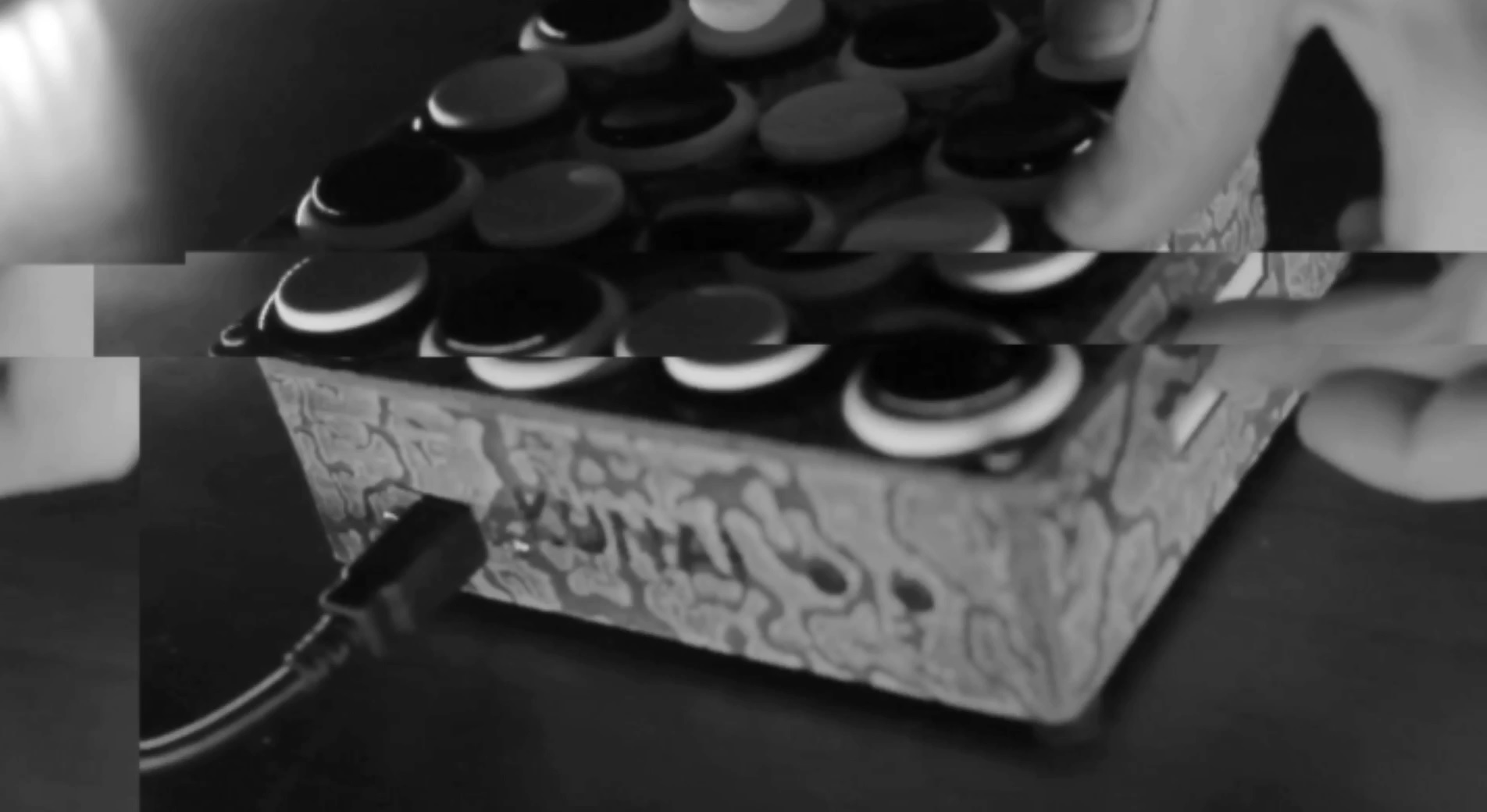
Now rout your Micro USB to B USB to end up coming out between the top two rows of clips to the left side ( reference picture for help )
Now onto the next step! Programming!
Coding the KUNAI
Since The KUNAI uses a TEENSY processor , it makes compiling code with ARDUINO stupid easy.
This code uses the "bounce" & "MIDI" libraries to look for button pushes, and then to send MIDI code * duh *
I won't break down the code here, as it's annotated pretty well!
You will need the Arduino Programmer and the teensyduino libraries, which can both be found by a quick google search.
Plug in your now "dumb" board into your computer and open up the ARDUINO program.
Now simply copy and paste this code into your ARDUINO program , or open the included .ino file with the ARDUINO program and set the following settings: Tools > Boards > Teensy LC
Tools > USB Type > MIDI
Tools > Port > Which ever port shows the Teensy
Now finally hit the arrow button top left to verify and upload the code!
NOW TIME TO TEST!
TESTING TIME
So... Now you technically have a working midi instrument, but we're not 100% sure if there's any shorts , or breaks in the traces & solder, so we need to test it!
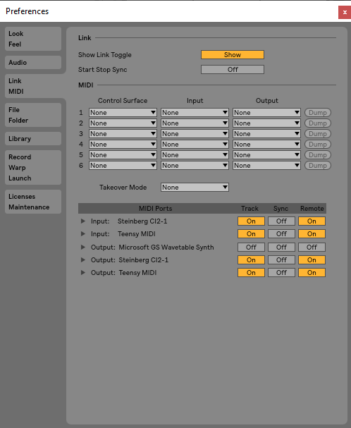
Open up your DAW like FL Studios or Ableton ( I will use Ableton for this example ) , and enable the Teensy MIDI device in MIDI options ( picture attached )
Now load up a drum rack ( onto a midi channel for ableton by going to instruments in the collections menu on the left, and double clicking the drum rack to load it up.
now start using a button, a wire or anything conductive, short each set of 2 clips on the board and watch for your LED's to turn on , and for the drum rack pad to light up relating to the set of pads you shorted; bottom left pad ( c1 ) is located on the bottom left of The KUNAI if the board is rotated 90 degrees clockwise.
If every set of standoffs shorting causes a pad launch + LED glow , then the standoffs are working correctly!
Now push the left tactile button and short the pads again , and watch for the lights in the bank of squares above the currently selected one to light up to ensure that your next pad button is working , once you have that working , press the right tactile button, which will return you to your active set of pad , short pads again, if you see the active grid light up , your bank buttons work!
To make sure that your touch filter works, enter midi mapping mode ctrl + m for Ableton on Windows ( command + m for Ableton on OSX ) or ctrl + j for FL Studio on windows ( Probably command j for FL Studios on OSX )
now click on any knob on your daw , then drag your finger along the touch filter, then exit MIDI map mode ( ctrl / command m for ableton , and I THINK FL studio automatically exists after each link ).
Now to finally test the filter, drag your finger along it again, and you should see the knob you clicked on , correlate with the position of your finger on the filter!
YAY!!! YOUR BOARD WORKS! NOW ONTO THE FINAL STEP OF ASSSEMBLY!
Final Assembly
Now you should have a 3D printed KUNAI base , a 3D printed KUNAI top , and an assembled Circuit Board!
First step is to put the buttons into the top panel , which is pretty self explanatory . just keep in mind that the button pins need to make *ROWS* instead of *COLUMNS* ( hard to explain ) as the board goes in turned 90 degrees, so if you have a pattern printed on the that needs to be oriented in a certain way, pay attention to that! OTHERWISE , just push the buttons in the same way so that the pins are aligned with the edges of the board creating 4 columns or row!
Now make sure your USB connector is in the correct position, align the pins from the bottom of the buttons into the fuse clips and push them into place! It's easiest to align a whole row or column at a time and push that row or column down at the same time instead of each button individually! Keep in mind that due to the drilling being manual and the placing of the buttons being manual , everything will NOT be perfectly aligned , you may have to finesse the button pin into the clip by slightly bending and twisting the top cover!
Once you have the top assembled , hot glue the tactile buttons into the cut outs in The KUNAI base , let it cool, then simply slide the touch filter into the slit; with the silver part of the filter facing out, and use a little bit of hot glue to keep the resistor and little blue tab secured to the body of The KUNAI so it stays out of the way of the PCB once it's put into the base!
Now simply drop the board and buttons into The KUNAI base , while putting the far edge in first ( edge with the tactile buttons ) and now the tricky part... Lining up the USB port with the cutout.
I find this easiest by using tweezers or a small hard tool to push around in the port until I see on of the screw holes through the cutout holes. Once you see one, secure one side with a screw ( don't fully tighten it yet ) , and then go fishing again for the second screw hole while the first one is still being held in place with the screws; once you've found it, screw in both screws and tighten them down ( I can never get it completely perfect with my model yet )
Now for the last steps screw the top panel into the bottom panel using the 30mm screws, and add the rubber feet to the corners on the bottom of the now finished KUNAI!
Support the Future of 3D Printed Instruments!

Thank you for checking out my tutorial, this project has no secrets behind it, but as you can see is a very tedious and expensive project! I make and sell these from my website @ www.themidiwork.shop
Thank you for all your support , and I hope you found this tutorial informative enough to make your own, or to have inspired you to purchase one from me!