The Home Octopus
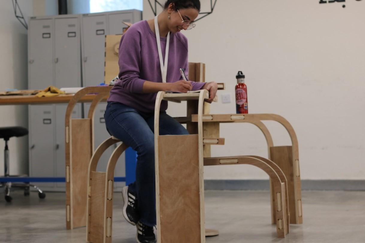
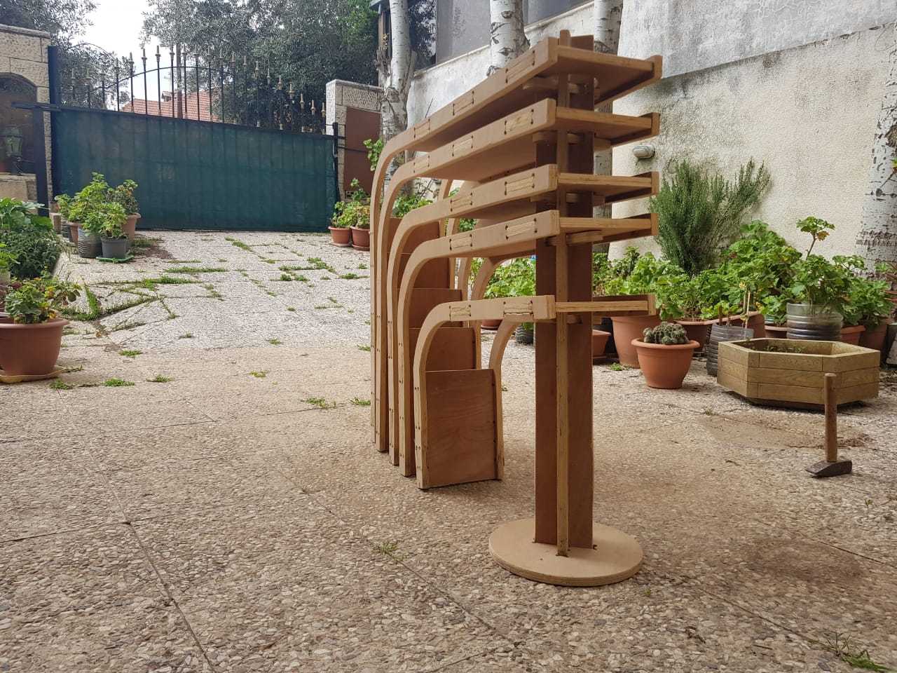
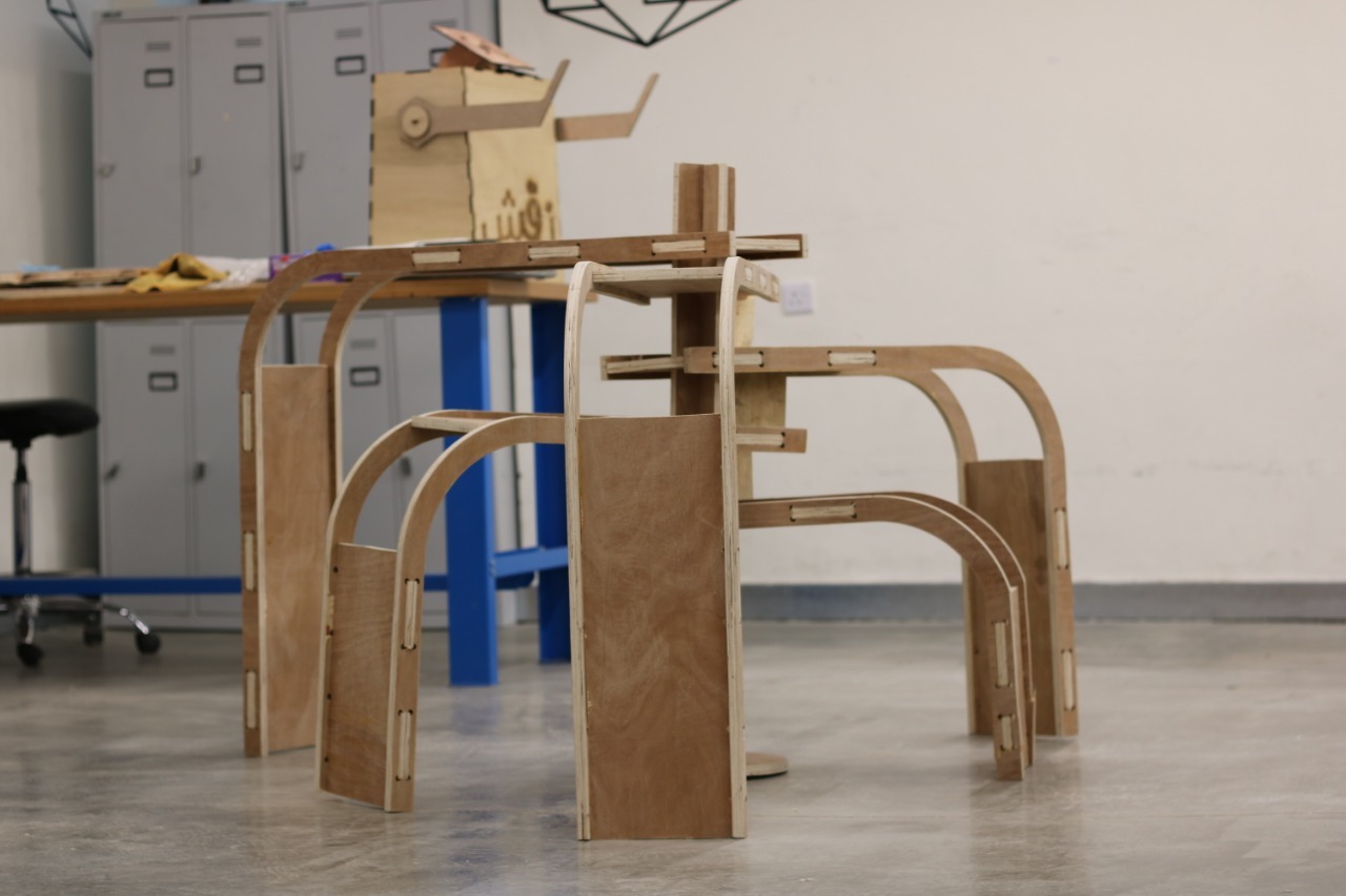
The Octopus Unit is a furniture solution to small spaces. It serves
as a multi-purpose piece. It can be used as a table, chair, stair, leg rest, pets' plaything, and whatever the user wants. When idle, the unit can be stacked in a way that takes little space.
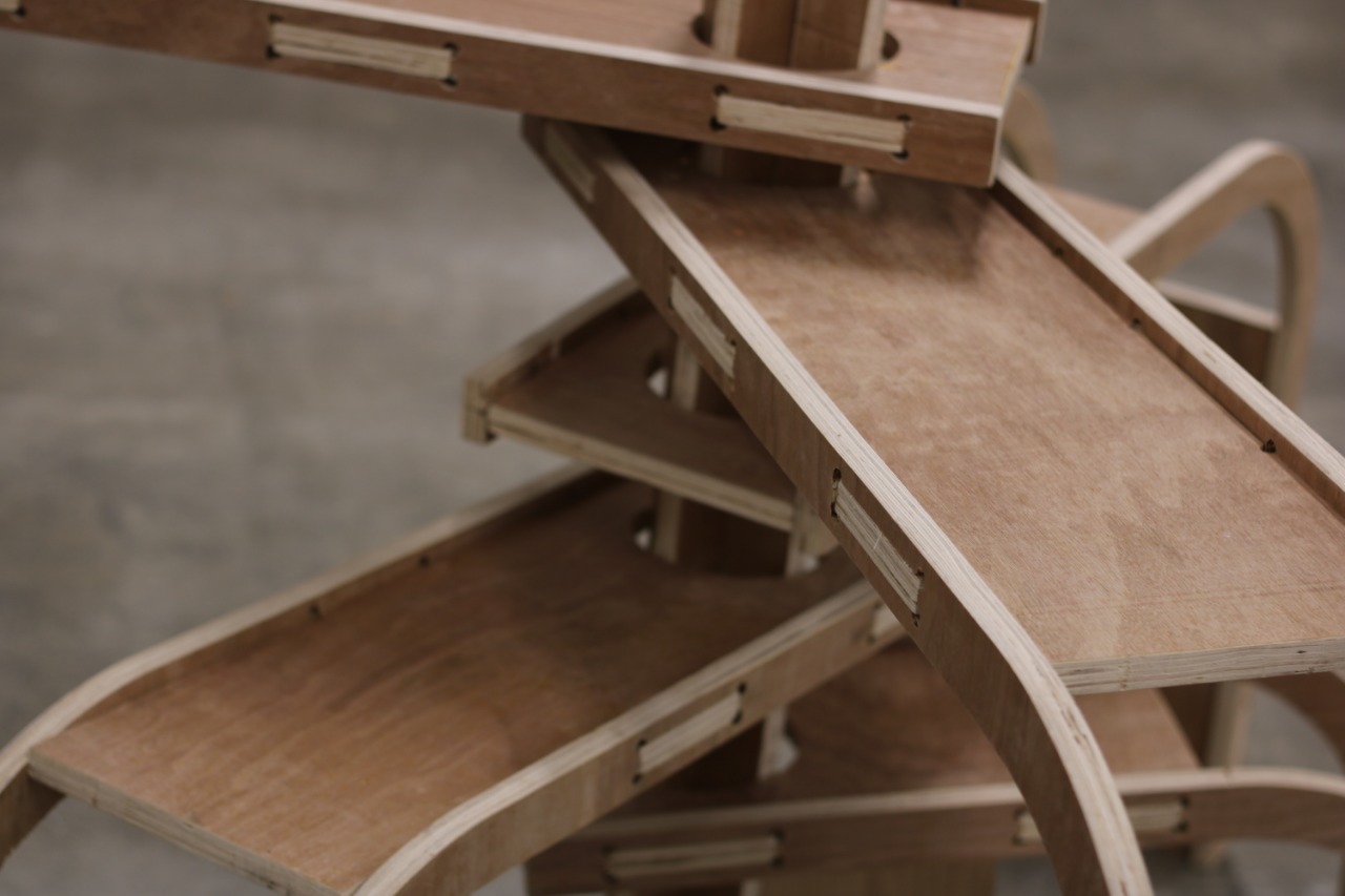
This unit consists of 28 wooden parts
interlocked together so that neither glue nor nails are needed to hold it together. The unit is also fun and easy to build, in the sense of adults building toy. Users are also free to pick and choose which parts they would like to keep and which to remove.
Supplies
A Wood CNC Machine
2 Wood Boards sized 244*122*18 mm Sheets, I used Plywood
Varnish/Paint (Optional)
Design (Or Just Download) the Parts.
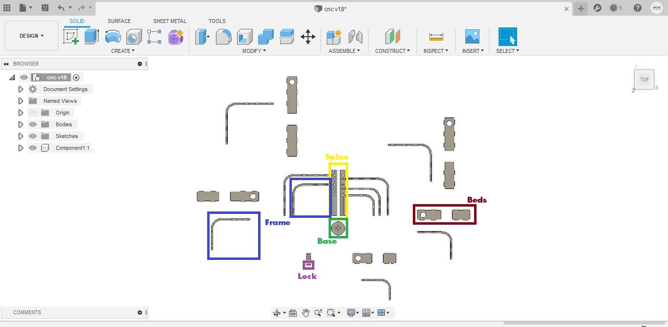
I started making the unit by designing the parts on Autodesk Fusion 360. The programs allows the user to draw complex shapes in a very user-friendly interface and logic.
Designing starts by "create sketch" and choosing the plane where you would like to draw on. From there, it is a simple process of drawing rectangles, circles, lines and trimming unnecessary things.
In the screenshot, you can see the 28 pieces as:
- 1 Base
- 2 Pieces of the spine
- 10 Frames (2 for each leg)
- 10 Beds (2 for each leg)
- 5 Locks
Once the design was ready, I saved the drawing in a .dxf extension in order to take it to the CNC machine.
Check the files here to download the DXF file or the original Fusion 360 file!
Preparing the Job
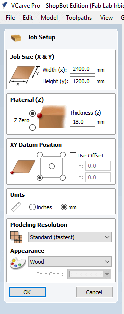

Now to prepare the job, I started using vCarve, but depending on the CNC you will be using you might use another software. I added a new file, and from the window on the screen I inserted the dimensions of the plywood board I’m using, but I added 4 and 2 cm allowance, so that when the cutting tool is working it won’t hit any fixing nails that might damage the head, also, I sat the Datum Position, which is where the spindle is in accordance to the XY axis.
Then, depending on your software, select the parts that you want to be cut from the inside together, as well as the parts that I want to be cut from outside the traces and on them. Every group of cuts that you want on the same side are chosen together, and the tool path is chosen for them (inside, outside, on the trace). With inside, I mean that I want the cutting tool to cut from the inside of the traces, this is used with the cuts in the bodies. With outside, I cut the outer cuts of the bodies
When you're cutting the inside or the outside, the program take the tool diameter into consideration, and so the resulting pieces had the same dimensions in the design. Another thing I used was to use climb cutting instead of conventional. The main difference between climb and conventional cutting is how the cutter bites into the material. A conventional cut deflects the bit towards the cut and a climb cut pushes the bit away. Climb cutting is often preferred when using a CNC router, as it causes less grain tearing or “tear-out.” However, climb cutting can be dangerous on a noncomputer controlled router, as the piece may be hard to control by hand and may “walk away.”
Next, you'll probably add the information of the cutting tool and other settings, I used the straight cutting tool so that the rear part of the pieces would have the same dimensions as the upper one. The pass depth is how low I want to cutting tool to go in the plate with each pass, the reason we add several passes with low depths is to get better finishing of the piece, and to lower the possibility of breaking the tool. It would also be good to know the following terms:
- Spindle Speed: rotational speed of the cutting tool in revolutions per min.
- Feed Rate: Surface speed at the center of the rotating tool.
- Plunge Rate: the distance in the z direction per pass that a cutting tool is plunged into the material.
I was advised by the CNC supervisor to use the default settings, but of course they can be calculated. you can get to know more about their calculations from here.
Another thing I added was tabs. Tabs are little links between the board and the piece I'm cutting it from. they are used to keep the cut pieces in place, and it could be easily removed later with a hammer.
Setting the Machine
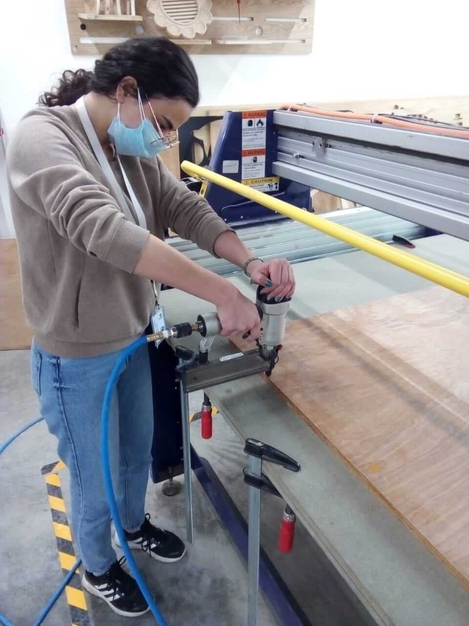
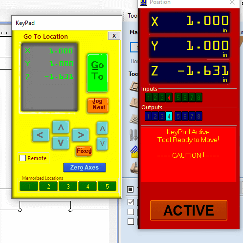
Place the wood board on the bed and fix it using a nail gun or clamps, and make sure the board is completely fixed, then proceed to set the XYZ axis.
on the ShopBot, setting X and Y axis is straight forward, you move the spindle from the ShopBot panel on the computer. As for the Z axis,you will place the calibration plate beneath the cutting tool on the board, and the alligator clip on the cutting tool, and then from the computer, the head automatically calibrated the Z access by lowering down till it touched the plate.
Run the Program & Wait
Not much to do here, just run the program and wait for the machine to finish the job.
Please note that you shouldn't leave the machine unattended, accidents happen and they may lead to bad results.
Once the job is done, remove the parts and get ready for the next step.
Finish the Parts
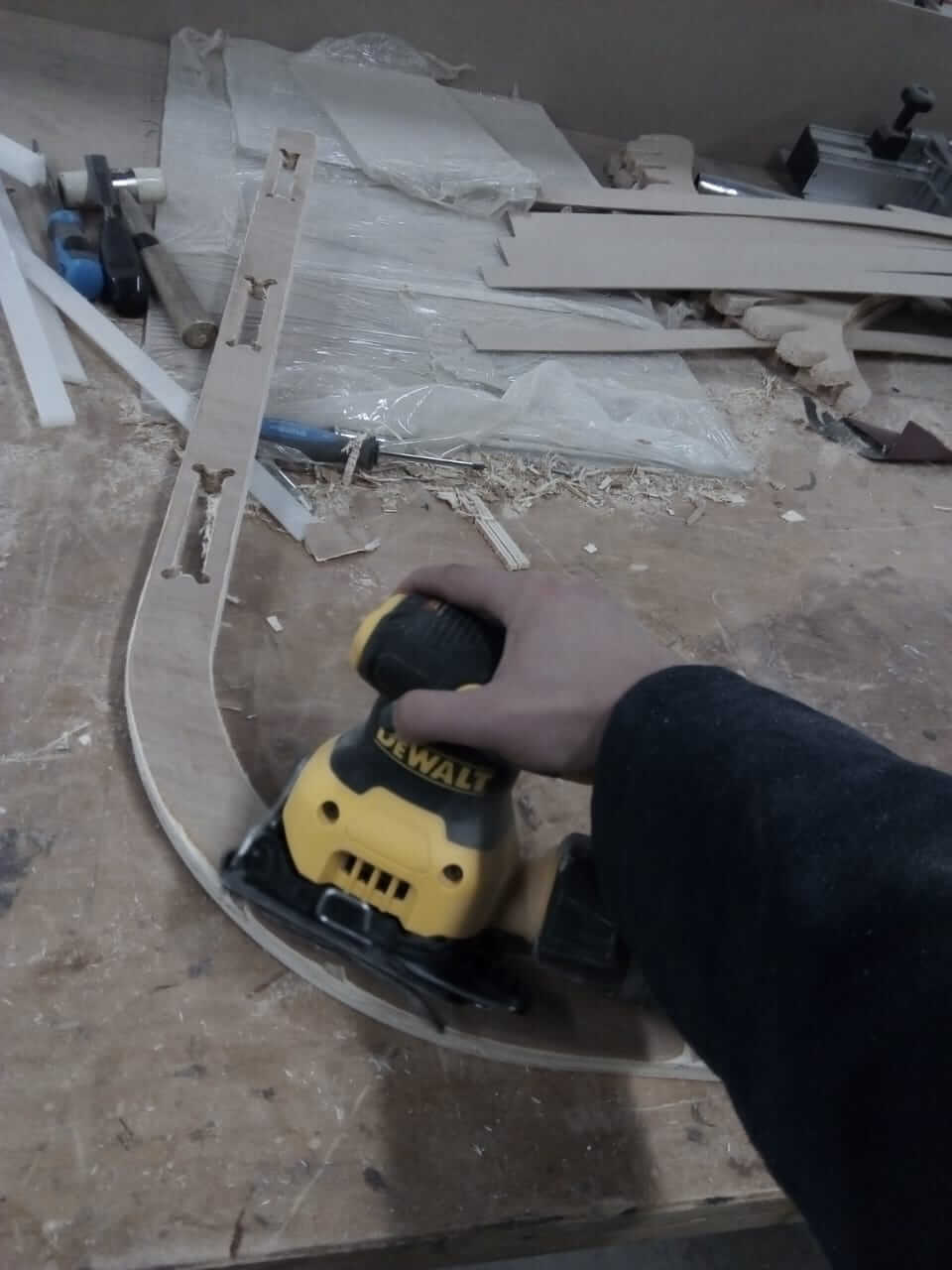
Use sanding paper on the resulting pieces to make them smoother, and then if you like, you can paint them or varnish the pieces.
Assemble
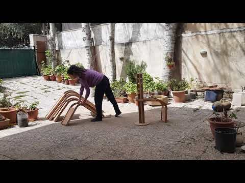
Place the beds between the frames according to their sizes, and then follow the steps in the video to assemble the pieces.
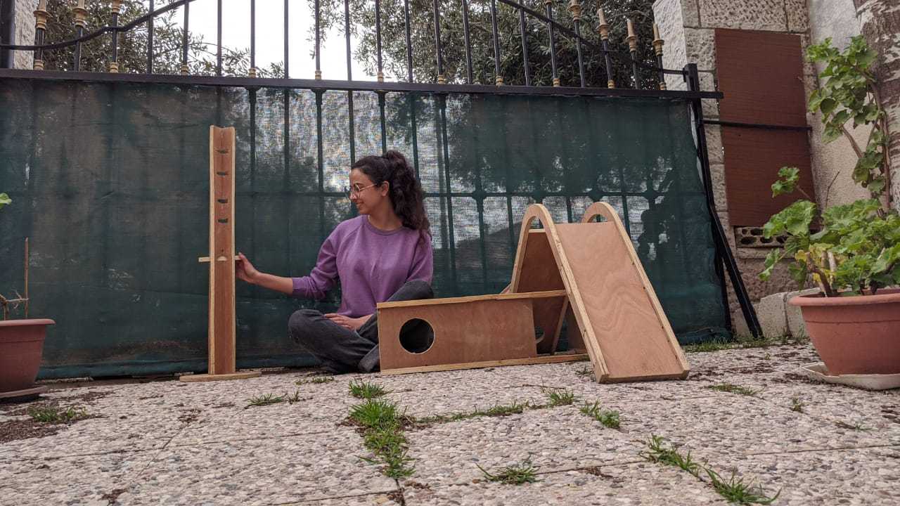
Enjoy!
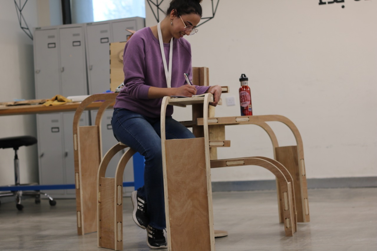
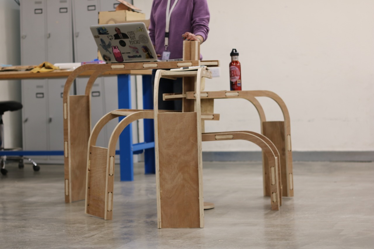
Get creative with how you would like to use the unit!